EP4191807A1 - Contact assembly - Google Patents
Contact assembly Download PDFInfo
- Publication number
- EP4191807A1 EP4191807A1 EP21849061.3A EP21849061A EP4191807A1 EP 4191807 A1 EP4191807 A1 EP 4191807A1 EP 21849061 A EP21849061 A EP 21849061A EP 4191807 A1 EP4191807 A1 EP 4191807A1
- Authority
- EP
- European Patent Office
- Prior art keywords
- contact
- contacts
- caught
- socket
- lamination direction
- Prior art date
- Legal status (The legal status is an assumption and is not a legal conclusion. Google has not performed a legal analysis and makes no representation as to the accuracy of the status listed.)
- Pending
Links
Images



Classifications
-
- H—ELECTRICITY
- H01—ELECTRIC ELEMENTS
- H01R—ELECTRICALLY-CONDUCTIVE CONNECTIONS; STRUCTURAL ASSOCIATIONS OF A PLURALITY OF MUTUALLY-INSULATED ELECTRICAL CONNECTING ELEMENTS; COUPLING DEVICES; CURRENT COLLECTORS
- H01R13/00—Details of coupling devices of the kinds covered by groups H01R12/70 or H01R24/00 - H01R33/00
- H01R13/02—Contact members
- H01R13/10—Sockets for co-operation with pins or blades
- H01R13/11—Resilient sockets
- H01R13/113—Resilient sockets co-operating with pins or blades having a rectangular transverse section
-
- H—ELECTRICITY
- H01—ELECTRIC ELEMENTS
- H01R—ELECTRICALLY-CONDUCTIVE CONNECTIONS; STRUCTURAL ASSOCIATIONS OF A PLURALITY OF MUTUALLY-INSULATED ELECTRICAL CONNECTING ELEMENTS; COUPLING DEVICES; CURRENT COLLECTORS
- H01R13/00—Details of coupling devices of the kinds covered by groups H01R12/70 or H01R24/00 - H01R33/00
- H01R13/02—Contact members
- H01R13/10—Sockets for co-operation with pins or blades
- H01R13/11—Resilient sockets
-
- H—ELECTRICITY
- H01—ELECTRIC ELEMENTS
- H01R—ELECTRICALLY-CONDUCTIVE CONNECTIONS; STRUCTURAL ASSOCIATIONS OF A PLURALITY OF MUTUALLY-INSULATED ELECTRICAL CONNECTING ELEMENTS; COUPLING DEVICES; CURRENT COLLECTORS
- H01R13/00—Details of coupling devices of the kinds covered by groups H01R12/70 or H01R24/00 - H01R33/00
- H01R13/02—Contact members
- H01R13/10—Sockets for co-operation with pins or blades
- H01R13/11—Resilient sockets
- H01R13/112—Resilient sockets forked sockets having two legs
-
- H—ELECTRICITY
- H01—ELECTRIC ELEMENTS
- H01R—ELECTRICALLY-CONDUCTIVE CONNECTIONS; STRUCTURAL ASSOCIATIONS OF A PLURALITY OF MUTUALLY-INSULATED ELECTRICAL CONNECTING ELEMENTS; COUPLING DEVICES; CURRENT COLLECTORS
- H01R13/00—Details of coupling devices of the kinds covered by groups H01R12/70 or H01R24/00 - H01R33/00
- H01R13/02—Contact members
- H01R13/15—Pins, blades or sockets having separate spring member for producing or increasing contact pressure
- H01R13/187—Pins, blades or sockets having separate spring member for producing or increasing contact pressure with spring member in the socket
-
- H—ELECTRICITY
- H01—ELECTRIC ELEMENTS
- H01R—ELECTRICALLY-CONDUCTIVE CONNECTIONS; STRUCTURAL ASSOCIATIONS OF A PLURALITY OF MUTUALLY-INSULATED ELECTRICAL CONNECTING ELEMENTS; COUPLING DEVICES; CURRENT COLLECTORS
- H01R13/00—Details of coupling devices of the kinds covered by groups H01R12/70 or H01R24/00 - H01R33/00
- H01R13/40—Securing contact members in or to a base or case; Insulating of contact members
-
- H—ELECTRICITY
- H01—ELECTRIC ELEMENTS
- H01R—ELECTRICALLY-CONDUCTIVE CONNECTIONS; STRUCTURAL ASSOCIATIONS OF A PLURALITY OF MUTUALLY-INSULATED ELECTRICAL CONNECTING ELEMENTS; COUPLING DEVICES; CURRENT COLLECTORS
- H01R25/00—Coupling parts adapted for simultaneous co-operation with two or more identical counterparts, e.g. for distributing energy to two or more circuits
- H01R25/16—Rails or bus-bars provided with a plurality of discrete connecting locations for counterparts
-
- H—ELECTRICITY
- H01—ELECTRIC ELEMENTS
- H01R—ELECTRICALLY-CONDUCTIVE CONNECTIONS; STRUCTURAL ASSOCIATIONS OF A PLURALITY OF MUTUALLY-INSULATED ELECTRICAL CONNECTING ELEMENTS; COUPLING DEVICES; CURRENT COLLECTORS
- H01R4/00—Electrically-conductive connections between two or more conductive members in direct contact, i.e. touching one another; Means for effecting or maintaining such contact; Electrically-conductive connections having two or more spaced connecting locations for conductors and using contact members penetrating insulation
- H01R4/06—Riveted connections
Definitions
- the present invention relates to a contact assembly including a plurality of electrical contacts.
- Patent Literature 1 discloses a header connector including a plurality of contact elements laminated and identical in shape, and a housing accommodating the contact element laminate. Each contact element is formed with a pair of spring beams at each of both ends. Once the contact elements are laminated, the pairs of spring beams of the laminate as a whole serve as a socket for receiving a mating counterpart. For example, the socket at one of the ends mates with a tab terminal, and the socket at the other end mates with a power busbar.
- An object of the present invention is to improve a structure including a contact laminate serving as a socket.
- the present invention is a contact assembly including a plurality of contacts serving as a socket in a laminated state, wherein the plurality of contacts each include a mating portion forming the socket, and a caught portion caught on each other in a lamination direction of the contacts.
- the plurality of contacts each include a mating portion forming the socket, and a caught portion caught on each other in a lamination direction of the contacts.
- the plurality of contacts at least two contacts adjacent to each other in the lamination direction have electrical continuity with each other via a spring compressible in the lamination direction between the respective caught portions.
- the adjacent contacts are partially or entirely separated and stacked together. That is, the adjacent contacts may also be separated while their outlines almost overlap each other in the lamination direction.
- the contact assembly of the present invention include a conductor laminated with the plurality of contacts, and the conductor have electrical continuity with the contact adjacent to the conductor in the lamination direction via a spring compressible in the lamination direction.
- the conductor extend in a direction crossing the lamination direction, and a contact group composed of the plurality of contacts be provided in each of a plurality of positions on the conductor.
- the plurality of contacts be caught by a fastening element passing through the caught portion with the spring compressed.
- the socket be adjustable in orientation by rotation of the plurality of contacts on the fastening element.
- the contact groups caught by the same fastening element serve as two or more of the sockets different in orientation.
- the caught portion include a plurality of the springs composed of a lanced tab around a through-hole passed through by the fastening element.
- the plurality of contacts include a first contact and a second contact having different arrangements of the springs in the caught portion, and the first contact and the second contact be positioned alternately in the lamination direction.
- the presence of the spring between the caught portions of the contacts laminated causes a clearance to be set between the mating portions of the contacts, thus enabling each contact to be located so as to be stacked together with the mating portions separated from each other.
- This can ensure that the mating portions are distributed in the lamination direction while a sufficient number of contacts laminated per unit thickness are secured.
- This further ensures that a large number of contact points are provided to the socket, and also enables an increase in the surface area of the contacts exposed to the air, as compared to a case where the caught portion does not include the spring, so that an increase in temperature can be suppressed by promoting heat dissipation from the contacts.
- each mating portion easily deflects in conformity to a mating counterpart. Therefore, a position error and/or a dimension and shape error is absorbed, which enables stable connection between the mating counterpart and the contact assembly, and the connection can also be retained even if an external force such as vibration is applied.
- an electrical connection between the mating counterpart received in the mating portions and the conductor having electrical continuity with the caught portion is also achieved.
- a contact assembly 1 shown in Figure 1 includes a contact group 10 serving as a socket S, a busbar 20 (conductor) laminated with the contact group 10, and a fastening element 30 integrating the contact group 10 and the busbar 20 together.
- the contact assembly 1 can be used, for example, for a power carrying circuit mounted on a vehicle or the like.
- the contact group 10 is composed of a plurality of contacts 11 laminated. As shown in Figure 2 , each contact 11 includes a mating portion 12 forming the socket S, and a caught portion 13 caught on each other in a lamination direction D1 of the contacts 11.
- the contacts 11 can be formed, for example, by stamping and forming a sheet made of a metal material such as an aluminum alloy.
- a clearance C ( Figure 3 ) is given between the mating portions 12 laminated. Though not shown in Figure 1 , a space as the clearance C is actually present between the mating portions 12.
- the positions of the clearances C are indicated by "C" in Figure 1 . The same applies to Figure 8 .
- the mating portion 12 is composed of a pair of arms 121 extending from the rectangular caught portion 13. Once the contacts 11 are laminated with their arms 121 oriented unidirectionally, the pairs of arms 121 of the laminate as a whole serve as the socket S ( Figure 1 ) for receiving a mating counterpart 9 ( Figure 3 ).
- the orientation of the socket S can be adjusted by rotating the contacts 11 on the fastening element 30 and changing the orientation of the arms 1 21.
- the socket S can be oriented in any direction.
- the mating counterpart 9 is, for example, a busbar other than the busbar 20, a tab terminal, or the like. Once the sheet-like mating counterpart 9 is mated into the socket S through a gap G at distal ends of the pairs of arms 121, the mating counterpart 9 comes into contact with respective contact point portions 122 of the mating portions 12 of the contact group 10.
- the caught portion 13 includes a through-hole 130 passing therethrough in a sheet thickness direction (the lamination direction D1), and a spring 131 compressible in the lamination direction D1 and positioned in the vicinity of and/or around the through-hole 130.
- the spring 131 is composed of a lanced tab formed by lancing like a cantilever on a first face 13A of the caught portion 13. It is preferred that a plurality of (three in the present embodiment) springs 131 be positioned around the through-hole 130.
- the plurality of contacts 11 laminated are caught on each other, with the spring 131 compressed, by the fastening element 30 ( Figures 1 and 3 ) passing through the through-holes 130 of the caught portions 13.
- the contact group 10, as shown in Figure 2 includes a first contact 11-1 and a second contact 11-2 having different arrangements of the springs 131 in the caught portion 13.
- the springs 131 (131-1) of the first contact 11-1 are positioned at equal intervals around the through-hole 130.
- the springs 131 (131-2) of the second contact 11-2 are positioned at equal intervals around the through-hole 130 but in different phases from the springs 131-1 of the first contact 11-1.
- each spring 131 be formed in the caught portion 13 such that a free end 131F lies in the vicinity of the through-hole 130.
- the shape, arrangement, and/or lancing direction of the spring 131 is not limited to those in the present embodiment but may be determined appropriately. Not only the spring 131 formed by lancing on the first face 13A but also the spring 131 formed by lancing on a second face 13B may be provided to the caught portion 13.
- the first contacts 11-1 and the second contacts 11-2 are positioned alternately in the lamination direction D1 (see Figure 3 ). This causes each spring 131-1 of the first contact 11-1 to be positioned between the springs 131-2 of the second contact in a circumferential direction of the through-hole 130, as shown by a long dashed doubleshort dashed line in Figure 2(b) .
- the busbar 20 is interposed between a subgroup of two or more contacts 11 and another subgroup of two or more contacts 11, and caught by the fastening element 30 along with the contact group 10.
- the fastening element 30 is passed through a connection hole 21 passing through the busbar 20 in the sheet thickness direction.
- the mating portions 12 of the contacts 11 project from the busbar 20.
- the first contacts 11-1 and the second contacts 11-2 are laminated alternately and oriented such that the free ends 131F of the springs 131 lie on a side toward the busbar 20 relative to the surface of the caught portion 13.
- the fastening element 30 includes, for example, a first pin 31, a second pin 32, and a washer 33, as shown in Figure 3 .
- the spring 131-1 of the first contact 11-1 is pressed against a flat portion not formed with the spring 131-2 in the caught portion 13 of the second contact 1 1-2.
- the spring 131-2 of the second contact 11-2 is pressed against a flat portion not formed with the spring 131-1 in the caught portion 13 of the first contact 11-1. Since the first contact 11-1 is adjacent to the busbar 20 in an example shown in Figure 3 , the spring 131-1 of the first contact 11-1 is pressed against the surface of the busbar 20.
- the mating portions 12 extending in the same direction from the respective caught portions 13 of the contact group 10 caught by the fastening element 30 serve as the socket S.
- Each caught portion 13 is located in the lamination direction D1 by the fastening element 30 and the spring 131.
- the mating portions 12 not including the springs 131 are located so as to be laminated via the clearances C.
- Each of the mating portions 12 laminated deflects to be displaced and deformed in appropriate directions including a direction along the sheet thickness direction (see an arrowed line in Figure 3 ) and a rotation direction of the shaft of the fastening element 30 (see an arrowed line in Figure 4 ), and thereby the socket S as a whole can conform to the mating counterpart 9.
- each mating portion 12 is displaced/deformed, by way of example, so as to expand at its distal end in a direction indicated by the arrowed line in Figure 3 .
- each mating portion 12 is displaced/deformed so as to expand on a pivot like a folding fan.
- each mating portion 12 may be displaced/deformed three-dimensionally both in the arrow direction in Figure 3 and in the arrow direction in Figure 4 .
- a space C2 is formed between the mating portion 12 of the contact 11 laminated on one face of the busbar 20 and the mating portion 12 of the contact 1 laminated on the other face of the busbar 20.
- the presence of this clearance C2 further facilitates displacement/deformation of the mating portions 12, thus enabling more satisfactory conformity to the mating counterpart 9.
- the contact assembly 1 since the contacts 11 conform to the mating counterpart 9 based on the laminate structure, respective position errors and/or dimension and shape errors of the mating counterpart 9 and the socket S are absorbed, so that the mating counterpart 9 and the contact assembly 1 can be stably connected, and their connection can also be retained even if an external force such as vibration is applied. Therefore, the reliability of connection can be ensured.
- each contact 11 can be located by the spring 131 with the fine clearance C set between the mating portions 12, it can be ensured that the mating portions are distributed in the lamination direction D1 while a sufficiently large number of contacts 11 laminated per unit thickness are secured. This can further ensure that a large number of contact points are provided to the socket S, as compared to a case where the contact assembly 1 does not include the spring 131, and also enables suppression of an increase in temperature by promotion of heat dissipation due to an increase in the surface area of the contact 11. The suppression of an increase in temperature enables avoidance of an increase in electrical resistance, which can contribute to an increase in power carrying capacity.
- the contact assembly 1 since the contact assembly 1 includes the busbar 20 laminated on the contacts 11, the freedom of wiring can be improved by increasing contact points in an extension direction of the busbar 20.
- the rectangular busbar 20 shown in Figure 5 extends in a direction crossing the lamination direction D1 (a direction perpendicular to the plane of paper of Figure 5 ).
- the busbar 20 is formed with a plurality of connection holes 21 at predetermined intervals in the extension direction.
- the contact group 10 composed of two or more contacts 11 can be provided in the respective positions of two or more connection holes 21 freely selected from these connection holes 21.
- a first contact group 10-1 ( Figure 1 ) is provided in the position of a first connection hole 21-1 of the busbar 20, a second contact group 10-2 is provided in the position of a second connection hole 21-2, and a third contact group 10-3 is provided in the position of a third connection hole 21-3.
- the first to third contact groups 10-1, 10-2, 10-3 are each fastened to the busbar 20 with fastening elements 30 given individually.
- the first contact group 10-1 serves as a socket S-1.
- the second contact group 10-2 serves as sockets S-2A, S-2B.
- the third contact group 10-3 serves as sockets S-3A, S-3B.
- the second contact group 10-2 are divided into a contact subgroup 10-2A fastened to the busbar 20 and oriented so as to have the mating portions 12 projecting in one of width directions D2 of the busbar 20, and a contact subgroup 10-2B fastened to the busbar 20 and oriented so as to have the mating portions 12 projecting in the other width direction D2 of the busbar 20.
- the contact subgroup 10-2A and the contact subgroup 10-2B may not necessarily be divided using the busbar as a boundary, and can be divided in any position in the lamination direction D1.
- the contact subgroup 10-2A positioned on the front face of the busbar 20 serves as the socket S-2A.
- the contact subgroup 10-2B positioned on the back face of the busbar 20 serves as another socket S-2B having a different orientation from the socket S-2A.
- the third contact group 10-3 are likewise divided into a contact subgroup 10-3A and a contact subgroup 10-3B.
- the contact subgroup 10-3A serves as the socket S-3A
- the contact subgroup 10-3B serves as the socket S-3B.
- Figure 6 shows an example of using a plurality of busbars 20-1, 20-2 to achieve a further increase in the number of contact points.
- a first contact group 10-1 serving as sockets S-1A, S-1B is provided in the position of a first connection hole 21-1 of the first busbar 20-1.
- the first contact group 10-1 in Figure 6 is composed of contacts 11W including a pair of mating portions 12-1, 12-2.
- a second contact group 10-2 serving as a socket S-2 is provided in the position of a second connection hole 21-2.
- a third contact group 10-3 serving as sockets S-3A, S-3B is provided in the position of a third connection hole 21-3.
- a fourth contact group 10-4 is provided in the position of a connection hole 21-4 of the second busbar 20-2.
- the fourth contact group 10-4 is divided in the lamination direction D1 into a contact subgroup 10-4A serving as a socket S-4A, a contact subgroup 10-4B serving as a socket S-4B, and a contact subgroup 10-4C serving as a socket S-4C.
- the contact group 10 caught by the same fastening element 30 can be divided for use into an appropriate number corresponding to the number of sockets S.
- the orientation of the socket S may be angled relative to the extension direction of the first busbar 20-1 and/or the second busbar 20-2.
- the shaft portion of the fastening element 30 passed through the second connection hole 21-2 is also passed through the connection hole 21-5 ( Figure 7 ) of the second busbar 20-2.
- This fastening element 30 connects the first busbar 20-1 and the second busbar 20-2 together.
- all the contacts 11 of the second contact group 10-2 are positioned between the first busbar 20-1 and the second busbar 20-2.
- the contacts 11 of the second contact group 10-2 shown in Figure 7 like the contacts 11 of the contact group 10 shown in Figure 3 , also deflect in conformity to a mating counterpart received in the socket S-2, and elastically supports the mating counterpart.
- the first contacts 11-1 and the second contacts 11-2 are alternately positioned such that the springs 131 project toward the first busbar 20-1.
- the first contacts 11-1 and the second contacts 11-2 are alternately positioned such that the springs 131 project toward the second busbar 20-2.
- the laminated contact group may include a contact which is flat on both faces.
- the individual contacts 11 are unidirectionally oriented such that, for example, the respective springs 131 of the contacts 11 project toward the first busbar 20-1.
- the second busbar 20-2 here can be provided with a spring projecting toward the adjacent contact 11.
- Figure 8 shows a contact assembly 2 not including a busbar 20.
- the contact assembly 2 includes a contact group 40 composed of two or more contacts 41 laminated, and a fastening element 30.
- the contact 41 includes a pair of mating portions 12-1, 12-2, and a caught portion 13 caught on each other in a lamination direction D1 by the fastening element 30.
- the first mating portions 12-1 in a laminated state constitute a socket S-41
- the second mating portions 12-2 in a laminated state constitute a socket S-42.
- the caught portion 13 of the contact 41 is formed with a plurality of springs 131, as in the first embodiment.
- the contact group 40 includes as the contacts 41 two types of contacts 41-1, 41-2 having the springs 131 different in position.
- the spring 131 of the contact 41-2 is positioned between the springs 131 of the contact 41-1, as shown by a broken line in Figure 8 .
- the fastening element 30 every spring 131 of the contacts 41-1, 41-2 is pressed against the opposing contact and elastically deforms. Therefore, the elastic force of the spring 131 causes the contacts 41 of the contact group 40 to have electrical continuity with each other.
- the mating portions 12 are located by the spring 131 with a clearance C therebetween, so that a larger number of contacts 41 can be densely positioned and distributed in the lamination direction D1 within a limited range.
- the contact group 40 of the second embodiment can also ensure the reliability of connection since the presence of the clearance C improves the conformability to a mating counterpart.
- contact groups 10, 40 may be configured by alternately laminating three types of contacts 11 (or 41) having springs 131 different in position.
- a means for catching a plurality of contacts 11 (or 41) on each other in a lamination direction D1 is not limited to fastening using a fastening element 30 or the like.
- contacts 11 may be caught on each other by puttying or otherwise sealing the insides (cavities) of through-holes 130 of caught portions 13 laminated.
- the contacts 11 may be caught on each other by inserting a C-ring, O-ring, or the like into the cavities and allowing it to exert an elastic force radially toward the outside of the through-holes 130.
Landscapes
- Coupling Device And Connection With Printed Circuit (AREA)
- Connection Or Junction Boxes (AREA)
- Connector Housings Or Holding Contact Members (AREA)
- Installation Of Bus-Bars (AREA)
Abstract
Description
- The present invention relates to a contact assembly including a plurality of electrical contacts.
-
Patent Literature 1 discloses a header connector including a plurality of contact elements laminated and identical in shape, and a housing accommodating the contact element laminate. Each contact element is formed with a pair of spring beams at each of both ends. Once the contact elements are laminated, the pairs of spring beams of the laminate as a whole serve as a socket for receiving a mating counterpart. For example, the socket at one of the ends mates with a tab terminal, and the socket at the other end mates with a power busbar. - PTL 1:
JP2019-523537A - The spring beams constituting the socket described in
Patent Literature 1 deflects in conformity to the mating counterpart. In addition, since the mating counterpart comes into contact with each of the contact elements laminated, a large number of contact points are provided. Therefore, once installed in a power circuit, the contact element laminate described inPatent Literature 1 can contribute to an increase in current carrying capacity based on the large number of contact points. An object of the present invention is to improve a structure including a contact laminate serving as a socket. - The present invention is a contact assembly including a plurality of contacts serving as a socket in a laminated state, wherein the plurality of contacts each include a mating portion forming the socket, and a caught portion caught on each other in a lamination direction of the contacts. Of the plurality of contacts, at least two contacts adjacent to each other in the lamination direction have electrical continuity with each other via a spring compressible in the lamination direction between the respective caught portions. The adjacent contacts are partially or entirely separated and stacked together. That is, the adjacent contacts may also be separated while their outlines almost overlap each other in the lamination direction.
- It is preferred that the contact assembly of the present invention include a conductor laminated with the plurality of contacts, and the conductor have electrical continuity with the contact adjacent to the conductor in the lamination direction via a spring compressible in the lamination direction.
- In the contact assembly of the present invention, it is preferred that the conductor extend in a direction crossing the lamination direction, and a contact group composed of the plurality of contacts be provided in each of a plurality of positions on the conductor.
- In the contact assembly of the present invention, it is preferred that the plurality of contacts be caught by a fastening element passing through the caught portion with the spring compressed.
- In the contact assembly of the present invention, it is preferred that the socket be adjustable in orientation by rotation of the plurality of contacts on the fastening element.
- In the contact assembly of the present invention, it is preferred that the contact groups caught by the same fastening element serve as two or more of the sockets different in orientation.
- In the contact assembly of the present invention, it is preferred that the caught portion include a plurality of the springs composed of a lanced tab around a through-hole passed through by the fastening element.
- In the contact assembly of the present invention, it is preferred that the plurality of contacts include a first contact and a second contact having different arrangements of the springs in the caught portion, and the first contact and the second contact be positioned alternately in the lamination direction.
- According to the contact assembly of the present invention, the presence of the spring between the caught portions of the contacts laminated causes a clearance to be set between the mating portions of the contacts, thus enabling each contact to be located so as to be stacked together with the mating portions separated from each other. This can ensure that the mating portions are distributed in the lamination direction while a sufficient number of contacts laminated per unit thickness are secured. This further ensures that a large number of contact points are provided to the socket, and also enables an increase in the surface area of the contacts exposed to the air, as compared to a case where the caught portion does not include the spring, so that an increase in temperature can be suppressed by promoting heat dissipation from the contacts. Furthermore, since the clearance is given between the mating portions, each mating portion easily deflects in conformity to a mating counterpart. Therefore, a position error and/or a dimension and shape error is absorbed, which enables stable connection between the mating counterpart and the contact assembly, and the connection can also be retained even if an external force such as vibration is applied. By not only establishing electrical continuity in the lamination direction between the caught portions via the spring, but also establishing electrical continuity between the caught portion and another conductor via the spring, an electrical connection between the mating counterpart received in the mating portions and the conductor having electrical continuity with the caught portion is also achieved.
-
-
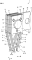
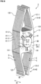
Figure 1 is an isometric view of a contact assembly according to a first embodiment of the present invention; -
Figures 2(a) and 2(b) are top views showing a first contact and a second contact included in a contact group shown inFigure 1 ,Figure 2(a) showing the first contact,Figure 2(b) showing the second contact having a different spring arrangement from the first contact; -
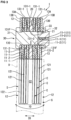
Figure 3 is a cross sectional view along a line III-III ofFigure 1 ; -
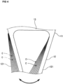
Figure 4 is a top view showing an example of a displaced and deformed state of mating portions of contacts laminated when a mating counterpart is inserted; -
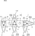
Figure 5 is a top view showing an example of assembly of contacts and a conductor (busbar); -
Figure 6 is a top view showing another example of assembly of contacts and conductors (busbars); -
Figure 7 is a cross sectional view along a line VI-VI ofFigure 5 ; and -
Figure 8 is an isometric view of a contact assembly according to a second embodiment of the present invention. - Each embodiment of the present invention will be described below with reference to the drawings. First Embodiment. A
contact assembly 1 shown inFigure 1 includes acontact group 10 serving as a socket S, a busbar 20 (conductor) laminated with thecontact group 10, and afastening element 30 integrating thecontact group 10 and thebusbar 20 together. Thecontact assembly 1 can be used, for example, for a power carrying circuit mounted on a vehicle or the like. - The
contact group 10 is composed of a plurality ofcontacts 11 laminated. As shown inFigure 2 , eachcontact 11 includes amating portion 12 forming the socket S, and a caughtportion 13 caught on each other in a lamination direction D1 of thecontacts 11. Thecontacts 11 can be formed, for example, by stamping and forming a sheet made of a metal material such as an aluminum alloy. It should be noted that a clearance C (Figure 3 ) is given between themating portions 12 laminated. Though not shown inFigure 1 , a space as the clearance C is actually present between themating portions 12. The positions of the clearances C are indicated by "C" inFigure 1 . The same applies toFigure 8 . - The
mating portion 12 is composed of a pair ofarms 121 extending from the rectangular caughtportion 13. Once thecontacts 11 are laminated with theirarms 121 oriented unidirectionally, the pairs ofarms 121 of the laminate as a whole serve as the socket S (Figure 1 ) for receiving a mating counterpart 9 (Figure 3 ). The orientation of the socket S can be adjusted by rotating thecontacts 11 on thefastening element 30 and changing the orientation of thearms 1 21. The socket S can be oriented in any direction. - The
mating counterpart 9 is, for example, a busbar other than thebusbar 20, a tab terminal, or the like. Once the sheet-like mating counterpart 9 is mated into the socket S through a gap G at distal ends of the pairs ofarms 121, themating counterpart 9 comes into contact with respectivecontact point portions 122 of themating portions 12 of thecontact group 10. - The caught
portion 13, as shown inFigures 2 and3 , includes a through-hole 130 passing therethrough in a sheet thickness direction (the lamination direction D1), and aspring 131 compressible in the lamination direction D1 and positioned in the vicinity of and/or around the through-hole 130. Thespring 131 is composed of a lanced tab formed by lancing like a cantilever on afirst face 13A of the caughtportion 13. It is preferred that a plurality of (three in the present embodiment)springs 131 be positioned around the through-hole 130. The plurality ofcontacts 11 laminated are caught on each other, with thespring 131 compressed, by the fastening element 30 (Figures 1 and3 ) passing through the through-holes 130 of the caughtportions 13. - The
contact group 10, as shown inFigure 2 , includes a first contact 11-1 and a second contact 11-2 having different arrangements of thesprings 131 in the caughtportion 13. The springs 131 (131-1) of the first contact 11-1 are positioned at equal intervals around the through-hole 130. The springs 131 (131-2) of the second contact 11-2 are positioned at equal intervals around the through-hole 130 but in different phases from the springs 131-1 of the first contact 11-1. - In order to facilitate positioning the springs 131-1 and the springs 131-2 in different phases, the springs 131-1, 131-2 are all formed radially around the through-
hole 130. In order to facilitate transmission of an axial force applied by thefastening element 30 to thesprings 131, it is preferred that eachspring 131 be formed in the caughtportion 13 such that afree end 131F lies in the vicinity of the through-hole 130. The shape, arrangement, and/or lancing direction of thespring 131 is not limited to those in the present embodiment but may be determined appropriately. Not only thespring 131 formed by lancing on thefirst face 13A but also thespring 131 formed by lancing on asecond face 13B may be provided to the caughtportion 13. - The first contacts 11-1 and the second contacts 11-2 are positioned alternately in the lamination direction D1 (see
Figure 3 ). This causes each spring 131-1 of the first contact 11-1 to be positioned between the springs 131-2 of the second contact in a circumferential direction of the through-hole 130, as shown by a long dashed doubleshort dashed line inFigure 2(b) . - In the present embodiment, the
busbar 20 is interposed between a subgroup of two ormore contacts 11 and another subgroup of two ormore contacts 11, and caught by thefastening element 30 along with thecontact group 10. Thefastening element 30 is passed through aconnection hole 21 passing through thebusbar 20 in the sheet thickness direction. Themating portions 12 of thecontacts 11 project from thebusbar 20. On both sides of thebusbar 20 in the lamination direction D1, the first contacts 11-1 and the second contacts 11-2 are laminated alternately and oriented such that the free ends 131F of thesprings 131 lie on a side toward thebusbar 20 relative to the surface of the caughtportion 13. - The
fastening element 30 includes, for example, afirst pin 31, asecond pin 32, and awasher 33, as shown inFigure 3 . Once a shaft portion of thefirst pin 31 inserted into the laminate of thecontacts 11 and thebusbar 20 through one side of the lamination direction D1 and a shaft portion of thesecond pin 32 inserted thereinto through the other side of the lamination direction D1 are screwed or otherwise coupled, such as by swaging, an axial force is applied to the laminate. The axial force causes thesprings 131 to be compressed between the respective caughtportions 13 of theadjacent contacts 11 and between thebusbar 20 and the caughtportion 13 of thecontact 11 adjacent to thebusbar 20, and elastically deform in the lamination direction D1. - Regarding the first contact 11-1 and the second contact 11-2, the spring 131-1 of the first contact 11-1 is pressed against a flat portion not formed with the spring 131-2 in the caught
portion 13 of thesecond contact 1 1-2. In addition, the spring 131-2 of the second contact 11-2 is pressed against a flat portion not formed with the spring 131-1 in the caughtportion 13 of the first contact 11-1. Since the first contact 11-1 is adjacent to thebusbar 20 in an example shown inFigure 3 , the spring 131-1 of the first contact 11-1 is pressed against the surface of thebusbar 20. - In this manner, electrical continuity is established using the elastic force of the
spring 131 between theadjacent contacts 11 and between thecontact 11 and thebusbar 20 adjacent to each other. - As shown in
Figure 3 , themating portions 12 extending in the same direction from the respective caughtportions 13 of thecontact group 10 caught by thefastening element 30 serve as the socket S. Each caughtportion 13 is located in the lamination direction D1 by thefastening element 30 and thespring 131. On the other hand, themating portions 12 not including thesprings 131 are located so as to be laminated via the clearances C. Each of themating portions 12 laminated deflects to be displaced and deformed in appropriate directions including a direction along the sheet thickness direction (see an arrowed line inFigure 3 ) and a rotation direction of the shaft of the fastening element 30 (see an arrowed line inFigure 4 ), and thereby the socket S as a whole can conform to themating counterpart 9. The presence of the clearance C between themating portions 12 facilitates deflection of eachmating portion 12, thus enabling themating portions 12 to conform to themating counterpart 9 sufficiently. Eachmating portion 12 is displaced/deformed, by way of example, so as to expand at its distal end in a direction indicated by the arrowed line inFigure 3 . Alternatively, as shown inFigure 4 , eachmating portion 12 is displaced/deformed so as to expand on a pivot like a folding fan. Alternatively, eachmating portion 12 may be displaced/deformed three-dimensionally both in the arrow direction inFigure 3 and in the arrow direction inFigure 4 . Therefore, even if themating counterpart 9 is, for example, angled relative to the lamination direction D1 and inserted into the socket S, the displacement and deformation of eachmating portion 12 cause the attitude of the socket S to follow themating counterpart 9. Furthermore, with eachmating portion 12 in contact with themating counterpart 9, the socket S elastically supports themating counterpart 9. At this time, since themating portions 12 of a large number ofcontacts 11 located in the lamination direction D1 by thesprings 131 are arranged with a narrow pitch with the clearances C therebetween, contact points corresponding in number to the contacts are provided between the socket S which themating portions 12 serves as and themating counterpart 9. - In the present embodiment, a space C2 is formed between the
mating portion 12 of thecontact 11 laminated on one face of thebusbar 20 and themating portion 12 of thecontact 1 laminated on the other face of thebusbar 20. The presence of this clearance C2 further facilitates displacement/deformation of themating portions 12, thus enabling more satisfactory conformity to themating counterpart 9. - According to the
contact assembly 1, since thecontacts 11 conform to themating counterpart 9 based on the laminate structure, respective position errors and/or dimension and shape errors of themating counterpart 9 and the socket S are absorbed, so that themating counterpart 9 and thecontact assembly 1 can be stably connected, and their connection can also be retained even if an external force such as vibration is applied. Therefore, the reliability of connection can be ensured. - According to the
contact assembly 1, since eachcontact 11 can be located by thespring 131 with the fine clearance C set between themating portions 12, it can be ensured that the mating portions are distributed in the lamination direction D1 while a sufficiently large number ofcontacts 11 laminated per unit thickness are secured. This can further ensure that a large number of contact points are provided to the socket S, as compared to a case where thecontact assembly 1 does not include thespring 131, and also enables suppression of an increase in temperature by promotion of heat dissipation due to an increase in the surface area of thecontact 11. The suppression of an increase in temperature enables avoidance of an increase in electrical resistance, which can contribute to an increase in power carrying capacity. - Furthermore, according to the
contact assembly 1, since thecontact assembly 1 includes thebusbar 20 laminated on thecontacts 11, the freedom of wiring can be improved by increasing contact points in an extension direction of thebusbar 20. Therectangular busbar 20 shown inFigure 5 extends in a direction crossing the lamination direction D1 (a direction perpendicular to the plane of paper ofFigure 5 ). Thebusbar 20 is formed with a plurality of connection holes 21 at predetermined intervals in the extension direction. Thecontact group 10 composed of two ormore contacts 11 can be provided in the respective positions of two or more connection holes 21 freely selected from these connection holes 21. - In an example shown in
Figure 5 , a first contact group 10-1 (Figure 1 ) is provided in the position of a first connection hole 21-1 of thebusbar 20, a second contact group 10-2 is provided in the position of a second connection hole 21-2, and a third contact group 10-3 is provided in the position of a third connection hole 21-3. The first to third contact groups 10-1, 10-2, 10-3 are each fastened to thebusbar 20 withfastening elements 30 given individually. The first contact group 10-1 serves as a socket S-1. The second contact group 10-2 serves as sockets S-2A, S-2B. The third contact group 10-3 serves as sockets S-3A, S-3B. - The second contact group 10-2 are divided into a contact subgroup 10-2A fastened to the
busbar 20 and oriented so as to have themating portions 12 projecting in one of width directions D2 of thebusbar 20, and a contact subgroup 10-2B fastened to thebusbar 20 and oriented so as to have themating portions 12 projecting in the other width direction D2 of thebusbar 20. It should be noted that the contact subgroup 10-2A and the contact subgroup 10-2B may not necessarily be divided using the busbar as a boundary, and can be divided in any position in the lamination direction D1. - In the plane of paper of
Figure 5 , the contact subgroup 10-2A positioned on the front face of thebusbar 20 serves as the socket S-2A. In addition, the contact subgroup 10-2B positioned on the back face of thebusbar 20 serves as another socket S-2B having a different orientation from the socket S-2A. In addition, the third contact group 10-3 are likewise divided into a contact subgroup 10-3A and a contact subgroup 10-3B. The contact subgroup 10-3A serves as the socket S-3A, and the contact subgroup 10-3B serves as the socket S-3B. -
Figure 6 shows an example of using a plurality of busbars 20-1, 20-2 to achieve a further increase in the number of contact points. In the example shown inFigure 6 , a first contact group 10-1 serving as sockets S-1A, S-1B is provided in the position of a first connection hole 21-1 of the first busbar 20-1. The first contact group 10-1 inFigure 6 is composed ofcontacts 11W including a pair of mating portions 12-1, 12-2. A second contact group 10-2 serving as a socket S-2 is provided in the position of a second connection hole 21-2. A third contact group 10-3 serving as sockets S-3A, S-3B is provided in the position of a third connection hole 21-3. In addition, a fourth contact group 10-4 is provided in the position of a connection hole 21-4 of the second busbar 20-2. The fourth contact group 10-4 is divided in the lamination direction D1 into a contact subgroup 10-4A serving as a socket S-4A, a contact subgroup 10-4B serving as a socket S-4B, and a contact subgroup 10-4C serving as a socket S-4C. - Like the contact group 10-3 or the contact group 10-4 described above, the
contact group 10 caught by thesame fastening element 30 can be divided for use into an appropriate number corresponding to the number of sockets S. The orientation of the socket S may be angled relative to the extension direction of the first busbar 20-1 and/or the second busbar 20-2. - The shaft portion of the
fastening element 30 passed through the second connection hole 21-2 is also passed through the connection hole 21-5 (Figure 7 ) of the second busbar 20-2. Thisfastening element 30 connects the first busbar 20-1 and the second busbar 20-2 together. At a location where the first busbar 20-1 and the second busbar 20-2 are connected together, for example, as shown inFigure 7 , all thecontacts 11 of the second contact group 10-2 are positioned between the first busbar 20-1 and the second busbar 20-2. Thecontacts 11 of the second contact group 10-2 shown inFigure 7 , like thecontacts 11 of thecontact group 10 shown inFigure 3 , also deflect in conformity to a mating counterpart received in the socket S-2, and elastically supports the mating counterpart. - In the example shown in
Figure 7 , on a side toward the first busbar 20-1 from the center in the lamination direction D1, the first contacts 11-1 and the second contacts 11-2 are alternately positioned such that thesprings 131 project toward the first busbar 20-1. On a side toward the second busbar 20-2, the first contacts 11-1 and the second contacts 11-2 are alternately positioned such that thesprings 131 project toward the second busbar 20-2. - This causes the first contact 11-1 and the second contact 11-2 lying centrally in the lamination direction D1 to have their flat faces in contact with each other, and have no electrical continuity with each other via the
spring 131. In this manner, even if someadjacent contacts 11 of the laminate have no electrical continuity with each other, the laminate of thecontacts 11 as a whole can achieve an increase in the number of contact points due to distribution of themating portions 12 with a narrow pitch, and can also contribute to suppression of an increase in temperature due to promotion of heat dissipation due to an increase in the surface area of thecontact 11. Furthermore, the conformability to themating counterpart 9 is also improved. Therefore, not all thecontacts 11 included in the laminated contact group are required to include thespring 131. The laminated contact group may include a contact which is flat on both faces. - In order to establish electrical continuity between all the
contacts 11 positioned between the first busbar 20-1 and the second busbar 20-2, as shown inFigure 7 , preferably, theindividual contacts 11 are unidirectionally oriented such that, for example, therespective springs 131 of thecontacts 11 project toward the first busbar 20-1. The second busbar 20-2 here can be provided with a spring projecting toward theadjacent contact 11. - Second Embodiment. Next, a second embodiment of the present invention will be described. A difference from the first embodiment will be mainly described below. The same components as the first embodiment will be denoted by the same reference signs.
Figure 8 shows acontact assembly 2 not including abusbar 20. Thecontact assembly 2 includes acontact group 40 composed of two ormore contacts 41 laminated, and afastening element 30. Thecontact 41 includes a pair of mating portions 12-1, 12-2, and a caughtportion 13 caught on each other in a lamination direction D1 by thefastening element 30. The first mating portions 12-1 in a laminated state constitute a socket S-41, and the second mating portions 12-2 in a laminated state constitute a socket S-42. - The caught
portion 13 of thecontact 41 is formed with a plurality ofsprings 131, as in the first embodiment. Thecontact group 40 includes as thecontacts 41 two types of contacts 41-1, 41-2 having thesprings 131 different in position. Thespring 131 of the contact 41-2 is positioned between thesprings 131 of the contact 41-1, as shown by a broken line inFigure 8 . - Once the contacts 41-1 and the contacts 41-2 alternately laminated are fastened by the
fastening element 30, everyspring 131 of the contacts 41-1, 41-2 is pressed against the opposing contact and elastically deforms. Therefore, the elastic force of thespring 131 causes thecontacts 41 of thecontact group 40 to have electrical continuity with each other. In the second embodiment, likewise, themating portions 12 are located by thespring 131 with a clearance C therebetween, so that a larger number ofcontacts 41 can be densely positioned and distributed in the lamination direction D1 within a limited range. Therefore, like the first embodiment, an increase in the number of contact points and suppression of an increase in temperature due to promotion of heat dissipation are achieved, and the suppression of an increase in temperature enables avoidance of an increase in electrical resistance, which can contribute to an increase in power carrying capacity. In addition, thecontact group 40 of the second embodiment can also ensure the reliability of connection since the presence of the clearance C improves the conformability to a mating counterpart. - Alternatively, a selection may be made from the configurations mentioned in the above embodiments, or an appropriate change into another configuration may be made, without departing from the spirit of the present invention.
- For example, if the sheet thickness of each
mating portion 12 is increased with the clearance C retained between themating portions 12, the area of contact between themating portion 12 and themate 9 is increased and thus the electrical resistance is reduced, which can suppress heat generation and contribute to suppression of an increase in temperature. In addition,contact groups springs 131 different in position. In addition, a means for catching a plurality of contacts 11 (or 41) on each other in a lamination direction D1 is not limited to fastening using afastening element 30 or the like. For example,contacts 11 may be caught on each other by puttying or otherwise sealing the insides (cavities) of through-holes 130 of caughtportions 13 laminated. Alternatively, thecontacts 11 may be caught on each other by inserting a C-ring, O-ring, or the like into the cavities and allowing it to exert an elastic force radially toward the outside of the through-holes 130. -
- 1, 2... contact assembly
- 9... mating counterpart
- 10, 40... contact group
- 10-1 to 10-4... first to fourth contact groups
- 11, 41... contact
- 1 1-1, 41-1... first contact
- 11-2,41-2... second contact
- 12, 12-1, 12-2... mating portion
- 13... caught portion
- 13A... first face
- 13B... second face
- 20... busbar (conductor)
- 20-1... first busbar (conductor)
- 20-1... second busbar (conductor)
- 21, 21-1 to 21-5... connection hole
- 30... fastening element
- 31... first pin
- 32... second pin
- 33... washer
- 121... arm
- 122... contact point portion
- 130... through-hole
- 131, 131-1, 131-2... spring
- 131F... free end
- C... clearance
- C2... space
- D1... lamination direction
- D2... width direction
- G... gap
- S, S-1 to S-4... socket
Claims (8)
- A contact assembly comprising a plurality of contacts serving as a socket in a laminated state, whereinthe plurality of contacts each comprise a mating portion forming the socket, and a caught portions caught on each other in a lamination direction of the contacts, andof the plurality of contacts, at least two contacts adjacent to each other in the lamination direction have electrical continuity with each other via a spring compressible in the lamination direction between the respective caught portions.
- The contact assembly according to claim 1, whereinthe contact assembly comprises a conductor laminated with the plurality of contacts, andthe conductor has electrical continuity with the contact adjacent to the conductor in the lamination direction via a spring compressible in the lamination direction.
- The contact assembly according to claim 2, whereinthe conductor extends in a direction crossing the lamination direction, anda contact group composed of the plurality of contacts is provided in each of a plurality of positions on the conductor.
- The contact assembly according to any one of claims 1 to 3, wherein
the plurality of contacts are caught by a fastening element passing through the caught portions with the spring compressed. - The contact assembly according to claim 4, wherein
the socket is adjustable in orientation by rotation of the plurality of contacts on the fastening element. - The contact assembly according to claim 4 or 5, wherein
the contact groups caught by the same fastening element serve as two or more of the sockets different in orientation. - The contact assembly according to any one of claims 4 to 6, wherein
the caught portion comprises a plurality of the springs composed of a lanced tab around a through-hole passed through by the fastening element. - The contact assembly according to claim 7, whereinthe plurality of contacts include a first contact and a second contact having different arrangements of the spring in the caught portion, andthe first contact and the second contact are positioned alternately in the lamination direction.
Applications Claiming Priority (2)
| Application Number | Priority Date | Filing Date | Title |
|---|---|---|---|
| JP2020130027A JP7601484B2 (en) | 2020-07-31 | 2020-07-31 | Contact Assembly |
| PCT/JP2021/008962 WO2022024437A1 (en) | 2020-07-31 | 2021-03-08 | Contact assembly |
Publications (2)
| Publication Number | Publication Date |
|---|---|
| EP4191807A1 true EP4191807A1 (en) | 2023-06-07 |
| EP4191807A4 EP4191807A4 (en) | 2024-07-31 |
Family
ID=80037887
Family Applications (1)
| Application Number | Title | Priority Date | Filing Date |
|---|---|---|---|
| EP21849061.3A Pending EP4191807A4 (en) | 2020-07-31 | 2021-03-08 | CONTACT ARRANGEMENT |
Country Status (6)
| Country | Link |
|---|---|
| US (1) | US12482977B2 (en) |
| EP (1) | EP4191807A4 (en) |
| JP (1) | JP7601484B2 (en) |
| KR (1) | KR20230042357A (en) |
| CN (1) | CN115917890A (en) |
| WO (1) | WO2022024437A1 (en) |
Families Citing this family (1)
| Publication number | Priority date | Publication date | Assignee | Title |
|---|---|---|---|---|
| JP7601484B2 (en) | 2020-07-31 | 2024-12-17 | TE Connectivity Japan合同会社 | Contact Assembly |
Family Cites Families (39)
| Publication number | Priority date | Publication date | Assignee | Title |
|---|---|---|---|---|
| US3427419A (en) * | 1966-03-31 | 1969-02-11 | Westinghouse Electric Corp | Disconnecting contact assembly for electrical apparatus |
| US4423917A (en) * | 1981-11-19 | 1984-01-03 | Amp Incorporated | Electrical connector having movable contact units |
| US4894029A (en) | 1989-03-17 | 1990-01-16 | Minnesota Mining And Manufacturing Company | Contact for metallized film |
| US5052953A (en) * | 1989-12-15 | 1991-10-01 | Amp Incorporated | Stackable connector assembly |
| JPH07111888B2 (en) * | 1993-07-12 | 1995-11-29 | 不二電機工業株式会社 | Power clip |
| JP3409250B2 (en) | 1999-01-04 | 2003-05-26 | 住友電装株式会社 | Electric circuit material and electric connection box provided with the electric circuit material |
| EP1018783B1 (en) | 1999-01-04 | 2003-06-18 | Sumitomo Wiring Systems, Ltd. | Electrical junction box having a bus bar |
| DE10117061A1 (en) | 2001-04-05 | 2002-10-10 | Delphi Tech Inc | Electrical connector e.g. for high current equipment in motor vehicles, includes stack of mutually aligned contact elements forming at least one connection section |
| DE10310899B3 (en) * | 2003-03-11 | 2004-05-19 | Lumberg Connect Gmbh & Co. Kg | Fork contact assembly complementary with blade contact carrying medium to high current, assembles fork springs on contact strips in flush arrangement |
| DE10352761B4 (en) * | 2003-11-12 | 2006-06-08 | Wolf Neumann-Henneberg | Connection contact for electrical contacting of a printed circuit board or a punched grid |
| JP2005294220A (en) * | 2004-04-05 | 2005-10-20 | Yamaichi Electronics Co Ltd | Female connector for high current |
| DE102004040834B3 (en) * | 2004-08-23 | 2006-04-06 | Wolf Neumann-Henneberg | plug contact |
| US7419407B1 (en) * | 2006-04-17 | 2008-09-02 | Seagate Technology Llc | Electrical connector with stacked contacts |
| US8123553B2 (en) * | 2006-10-17 | 2012-02-28 | Ls Industrial Systems Co., Ltd. | Conductor base and finger module of air circuit breaker |
| US7909663B1 (en) * | 2009-12-08 | 2011-03-22 | Olivier Bouffet | Modular optimized plug-in jaw |
| JP5631080B2 (en) | 2010-07-02 | 2014-11-26 | 日本航空電子工業株式会社 | connector |
| DE102010044612A1 (en) | 2010-09-01 | 2012-03-01 | Itt Manufacturing Enterprises, Inc. | Electrically conductive contact arrangement |
| US8197289B1 (en) * | 2011-01-25 | 2012-06-12 | Schneider Electric USA, Inc. | Self-locking power connector |
| US20160020052A1 (en) * | 2013-03-11 | 2016-01-21 | Schneider Electric USA, Inc. | Self-aligning power connection system with positive-latch connection |
| DE102013013458B3 (en) * | 2013-08-14 | 2014-10-30 | Lisa Dräxlmaier GmbH | contact element |
| US10128624B2 (en) | 2016-08-01 | 2018-11-13 | Te Connectivity Corporation | Power connector system |
| US10998675B2 (en) * | 2016-08-22 | 2021-05-04 | Interplex Industries, Inc. | Electrical connector |
| US10763607B2 (en) * | 2016-08-22 | 2020-09-01 | Interplex Industries, Inc. | Electrical connector |
| US10522945B2 (en) * | 2016-08-22 | 2019-12-31 | Interplex Industries, Inc. | Electrical connector |
| BE1025701B1 (en) * | 2017-11-10 | 2019-06-11 | Phoenix Contact Gmbh & Co. Kg | Buchsenlötkontakt and contact module for a printed circuit board |
| US11362444B2 (en) * | 2018-06-27 | 2022-06-14 | Interplex Industries, Inc. | Laminated wire connector |
| EP3624153B1 (en) * | 2018-09-17 | 2022-10-26 | Microelettrica Scientifica S.p.A. | Gripping group for a switch having an internal compact structure |
| US11355902B2 (en) * | 2019-01-28 | 2022-06-07 | TE Connectivity Services Gmbh | Power connector for a bus bar |
| KR102302096B1 (en) * | 2019-02-25 | 2021-09-13 | 엘에스일렉트릭(주) | Connector for bus bar |
| JP7111888B2 (en) | 2019-03-29 | 2022-08-02 | 豊田鉄工株式会社 | Laminated interior parts |
| US11855398B2 (en) * | 2019-04-19 | 2023-12-26 | Interplex Industries, Inc. | Multipart connector for conveying power |
| CN112928512B (en) * | 2019-12-05 | 2023-01-31 | 泰科电子(上海)有限公司 | Electrical connector |
| BE1028298B1 (en) * | 2020-05-12 | 2021-12-16 | Phoenix Contact Gmbh & Co | Connection unit, connection arrangement and electronic device |
| JP7601484B2 (en) | 2020-07-31 | 2024-12-17 | TE Connectivity Japan合同会社 | Contact Assembly |
| CN113571943A (en) * | 2021-08-17 | 2021-10-29 | 长春捷翼汽车零部件有限公司 | Flat belt and terminal insertion structure and motor vehicle |
| US12191614B2 (en) * | 2021-08-26 | 2025-01-07 | Te Connectivity Brasil Industria De Eletronicos Ltda. | Header power connector |
| CN217215185U (en) * | 2021-12-23 | 2022-08-16 | 长春捷翼汽车零部件有限公司 | Plug terminal and plug terminal mounting structure |
| CN118783158A (en) * | 2023-04-03 | 2024-10-15 | 泰科电子(上海)有限公司 | Connectors and Connector Assemblies |
| EP4503354B1 (en) * | 2023-08-03 | 2026-02-18 | ABB S.p.A. | Clamping device for a withdrawable low-voltage circuit breaker unit |
-
2020
- 2020-07-31 JP JP2020130027A patent/JP7601484B2/en active Active
-
2021
- 2021-03-08 EP EP21849061.3A patent/EP4191807A4/en active Pending
- 2021-03-08 WO PCT/JP2021/008962 patent/WO2022024437A1/en not_active Ceased
- 2021-03-08 CN CN202180050065.5A patent/CN115917890A/en active Pending
- 2021-03-08 KR KR1020237006688A patent/KR20230042357A/en active Pending
-
2023
- 2023-01-31 US US18/162,041 patent/US12482977B2/en active Active
Also Published As
| Publication number | Publication date |
|---|---|
| KR20230042357A (en) | 2023-03-28 |
| CN115917890A (en) | 2023-04-04 |
| JP2022026508A (en) | 2022-02-10 |
| JP7601484B2 (en) | 2024-12-17 |
| EP4191807A4 (en) | 2024-07-31 |
| US12482977B2 (en) | 2025-11-25 |
| WO2022024437A1 (en) | 2022-02-03 |
| US20230178919A1 (en) | 2023-06-08 |
Similar Documents
| Publication | Publication Date | Title |
|---|---|---|
| US10050394B2 (en) | Contact element for a plug arrangement in a bus system, more particularly an externally routed bus system | |
| US3270251A (en) | Electrical connecting system and parts | |
| TWI593197B (en) | Power connector assembly having an alignment body | |
| EP0009314A1 (en) | Electrical connector and connecting element | |
| WO1995030259A1 (en) | Conductive shroud for electrical connectors | |
| CN110176677B (en) | Contact and bus arrangement system | |
| CN114175410B (en) | Safe, stable, compact connector | |
| EP4191807A1 (en) | Contact assembly | |
| US20250149748A1 (en) | Connection module set, electrode connection member set, and battery pack | |
| JP7144332B2 (en) | Connector, wiring board assembly and connection structure | |
| CN114284773A (en) | Connector with a locking member | |
| US20260088523A1 (en) | Connection element for electrically connecting electronic elements | |
| JP4266776B2 (en) | Plug-in contact and connection structure of plug-in contact | |
| CN115732862A (en) | battery pack | |
| CN110168819B (en) | Joint connector | |
| CN220172398U (en) | Electrical connector and power terminal | |
| CN217740806U (en) | Bus duct joint, joint device and bus duct | |
| EP4106110A1 (en) | Electrical high-voltage circuit board plug contact device and power-electric circuit board connection | |
| US20250149723A1 (en) | Wiring module and battery pack | |
| US20250149760A1 (en) | Wiring module and battery pack | |
| TWI853450B (en) | Slotted lug, electrical interconnect and method of establishing an electrical connection | |
| CN222233904U (en) | Busbar for electric connector and electric connector | |
| US20250309598A1 (en) | Conductive terminal structure and socket | |
| CN1066581C (en) | Electrical distribution box and method of making | |
| US20250202138A1 (en) | Conductor assembly having a sleeve |
Legal Events
| Date | Code | Title | Description |
|---|---|---|---|
| STAA | Information on the status of an ep patent application or granted ep patent |
Free format text: STATUS: THE INTERNATIONAL PUBLICATION HAS BEEN MADE |
|
| PUAI | Public reference made under article 153(3) epc to a published international application that has entered the european phase |
Free format text: ORIGINAL CODE: 0009012 |
|
| STAA | Information on the status of an ep patent application or granted ep patent |
Free format text: STATUS: REQUEST FOR EXAMINATION WAS MADE |
|
| 17P | Request for examination filed |
Effective date: 20230227 |
|
| AK | Designated contracting states |
Kind code of ref document: A1 Designated state(s): AL AT BE BG CH CY CZ DE DK EE ES FI FR GB GR HR HU IE IS IT LI LT LU LV MC MK MT NL NO PL PT RO RS SE SI SK SM TR |
|
| DAV | Request for validation of the european patent (deleted) | ||
| DAX | Request for extension of the european patent (deleted) | ||
| REG | Reference to a national code |
Ref country code: DE Ref legal event code: R079 Free format text: PREVIOUS MAIN CLASS: H01R0025160000 Ipc: H01R0013110000 |
|
| A4 | Supplementary search report drawn up and despatched |
Effective date: 20240703 |
|
| RIC1 | Information provided on ipc code assigned before grant |
Ipc: H01R 4/06 20060101ALN20240627BHEP Ipc: H01R 13/11 20060101AFI20240627BHEP |
|
| RAP3 | Party data changed (applicant data changed or rights of an application transferred) |
Owner name: TE CONNECTIVITY JAPAN G.K. |