EP4191753A1 - Energiespeichersystem - Google Patents
Energiespeichersystem Download PDFInfo
- Publication number
- EP4191753A1 EP4191753A1 EP22211156.9A EP22211156A EP4191753A1 EP 4191753 A1 EP4191753 A1 EP 4191753A1 EP 22211156 A EP22211156 A EP 22211156A EP 4191753 A1 EP4191753 A1 EP 4191753A1
- Authority
- EP
- European Patent Office
- Prior art keywords
- layer
- energy storage
- storage system
- pressure
- insulation
- Prior art date
- Legal status (The legal status is an assumption and is not a legal conclusion. Google has not performed a legal analysis and makes no representation as to the accuracy of the status listed.)
- Pending
Links
Images










Classifications
-
- H—ELECTRICITY
- H01—ELECTRIC ELEMENTS
- H01M—PROCESSES OR MEANS, e.g. BATTERIES, FOR THE DIRECT CONVERSION OF CHEMICAL ENERGY INTO ELECTRICAL ENERGY
- H01M10/00—Secondary cells; Manufacture thereof
- H01M10/60—Heating or cooling; Temperature control
- H01M10/65—Means for temperature control structurally associated with the cells
- H01M10/653—Means for temperature control structurally associated with the cells characterised by electrically insulating or thermally conductive materials
-
- H—ELECTRICITY
- H01—ELECTRIC ELEMENTS
- H01M—PROCESSES OR MEANS, e.g. BATTERIES, FOR THE DIRECT CONVERSION OF CHEMICAL ENERGY INTO ELECTRICAL ENERGY
- H01M50/00—Constructional details or processes of manufacture of the non-active parts of electrochemical cells other than fuel cells, e.g. hybrid cells
- H01M50/20—Mountings; Secondary casings or frames; Racks, modules or packs; Suspension devices; Shock absorbers; Transport or carrying devices; Holders
- H01M50/233—Mountings; Secondary casings or frames; Racks, modules or packs; Suspension devices; Shock absorbers; Transport or carrying devices; Holders characterised by physical properties of casings or racks, e.g. dimensions
- H01M50/242—Mountings; Secondary casings or frames; Racks, modules or packs; Suspension devices; Shock absorbers; Transport or carrying devices; Holders characterised by physical properties of casings or racks, e.g. dimensions adapted for protecting batteries against vibrations, collision impact or swelling
-
- H—ELECTRICITY
- H01—ELECTRIC ELEMENTS
- H01M—PROCESSES OR MEANS, e.g. BATTERIES, FOR THE DIRECT CONVERSION OF CHEMICAL ENERGY INTO ELECTRICAL ENERGY
- H01M10/00—Secondary cells; Manufacture thereof
- H01M10/04—Construction or manufacture in general
- H01M10/0481—Compression means other than compression means for stacks of electrodes and separators
-
- H—ELECTRICITY
- H01—ELECTRIC ELEMENTS
- H01M—PROCESSES OR MEANS, e.g. BATTERIES, FOR THE DIRECT CONVERSION OF CHEMICAL ENERGY INTO ELECTRICAL ENERGY
- H01M10/00—Secondary cells; Manufacture thereof
- H01M10/60—Heating or cooling; Temperature control
- H01M10/61—Types of temperature control
- H01M10/613—Cooling or keeping cold
-
- H—ELECTRICITY
- H01—ELECTRIC ELEMENTS
- H01M—PROCESSES OR MEANS, e.g. BATTERIES, FOR THE DIRECT CONVERSION OF CHEMICAL ENERGY INTO ELECTRICAL ENERGY
- H01M10/00—Secondary cells; Manufacture thereof
- H01M10/60—Heating or cooling; Temperature control
- H01M10/62—Heating or cooling; Temperature control specially adapted for specific applications
- H01M10/625—Vehicles
-
- H—ELECTRICITY
- H01—ELECTRIC ELEMENTS
- H01M—PROCESSES OR MEANS, e.g. BATTERIES, FOR THE DIRECT CONVERSION OF CHEMICAL ENERGY INTO ELECTRICAL ENERGY
- H01M10/00—Secondary cells; Manufacture thereof
- H01M10/60—Heating or cooling; Temperature control
- H01M10/65—Means for temperature control structurally associated with the cells
- H01M10/655—Solid structures for heat exchange or heat conduction
- H01M10/6556—Solid parts with flow channel passages or pipes for heat exchange
-
- H—ELECTRICITY
- H01—ELECTRIC ELEMENTS
- H01M—PROCESSES OR MEANS, e.g. BATTERIES, FOR THE DIRECT CONVERSION OF CHEMICAL ENERGY INTO ELECTRICAL ENERGY
- H01M10/00—Secondary cells; Manufacture thereof
- H01M10/60—Heating or cooling; Temperature control
- H01M10/65—Means for temperature control structurally associated with the cells
- H01M10/658—Means for temperature control structurally associated with the cells by thermal insulation or shielding
-
- H—ELECTRICITY
- H01—ELECTRIC ELEMENTS
- H01M—PROCESSES OR MEANS, e.g. BATTERIES, FOR THE DIRECT CONVERSION OF CHEMICAL ENERGY INTO ELECTRICAL ENERGY
- H01M50/00—Constructional details or processes of manufacture of the non-active parts of electrochemical cells other than fuel cells, e.g. hybrid cells
- H01M50/20—Mountings; Secondary casings or frames; Racks, modules or packs; Suspension devices; Shock absorbers; Transport or carrying devices; Holders
- H01M50/204—Racks, modules or packs for multiple batteries or multiple cells
- H01M50/207—Racks, modules or packs for multiple batteries or multiple cells characterised by their shape
- H01M50/209—Racks, modules or packs for multiple batteries or multiple cells characterised by their shape adapted for prismatic or rectangular cells
-
- H—ELECTRICITY
- H01—ELECTRIC ELEMENTS
- H01M—PROCESSES OR MEANS, e.g. BATTERIES, FOR THE DIRECT CONVERSION OF CHEMICAL ENERGY INTO ELECTRICAL ENERGY
- H01M50/00—Constructional details or processes of manufacture of the non-active parts of electrochemical cells other than fuel cells, e.g. hybrid cells
- H01M50/20—Mountings; Secondary casings or frames; Racks, modules or packs; Suspension devices; Shock absorbers; Transport or carrying devices; Holders
- H01M50/218—Mountings; Secondary casings or frames; Racks, modules or packs; Suspension devices; Shock absorbers; Transport or carrying devices; Holders characterised by the material
- H01M50/22—Mountings; Secondary casings or frames; Racks, modules or packs; Suspension devices; Shock absorbers; Transport or carrying devices; Holders characterised by the material of the casings or racks
- H01M50/222—Inorganic material
-
- H—ELECTRICITY
- H01—ELECTRIC ELEMENTS
- H01M—PROCESSES OR MEANS, e.g. BATTERIES, FOR THE DIRECT CONVERSION OF CHEMICAL ENERGY INTO ELECTRICAL ENERGY
- H01M50/00—Constructional details or processes of manufacture of the non-active parts of electrochemical cells other than fuel cells, e.g. hybrid cells
- H01M50/20—Mountings; Secondary casings or frames; Racks, modules or packs; Suspension devices; Shock absorbers; Transport or carrying devices; Holders
- H01M50/218—Mountings; Secondary casings or frames; Racks, modules or packs; Suspension devices; Shock absorbers; Transport or carrying devices; Holders characterised by the material
- H01M50/22—Mountings; Secondary casings or frames; Racks, modules or packs; Suspension devices; Shock absorbers; Transport or carrying devices; Holders characterised by the material of the casings or racks
- H01M50/231—Mountings; Secondary casings or frames; Racks, modules or packs; Suspension devices; Shock absorbers; Transport or carrying devices; Holders characterised by the material of the casings or racks having a layered structure
-
- H—ELECTRICITY
- H01—ELECTRIC ELEMENTS
- H01M—PROCESSES OR MEANS, e.g. BATTERIES, FOR THE DIRECT CONVERSION OF CHEMICAL ENERGY INTO ELECTRICAL ENERGY
- H01M50/00—Constructional details or processes of manufacture of the non-active parts of electrochemical cells other than fuel cells, e.g. hybrid cells
- H01M50/20—Mountings; Secondary casings or frames; Racks, modules or packs; Suspension devices; Shock absorbers; Transport or carrying devices; Holders
- H01M50/233—Mountings; Secondary casings or frames; Racks, modules or packs; Suspension devices; Shock absorbers; Transport or carrying devices; Holders characterised by physical properties of casings or racks, e.g. dimensions
-
- H—ELECTRICITY
- H01—ELECTRIC ELEMENTS
- H01M—PROCESSES OR MEANS, e.g. BATTERIES, FOR THE DIRECT CONVERSION OF CHEMICAL ENERGY INTO ELECTRICAL ENERGY
- H01M50/00—Constructional details or processes of manufacture of the non-active parts of electrochemical cells other than fuel cells, e.g. hybrid cells
- H01M50/20—Mountings; Secondary casings or frames; Racks, modules or packs; Suspension devices; Shock absorbers; Transport or carrying devices; Holders
- H01M50/244—Secondary casings; Racks; Suspension devices; Carrying devices; Holders characterised by their mounting method
-
- H—ELECTRICITY
- H01—ELECTRIC ELEMENTS
- H01M—PROCESSES OR MEANS, e.g. BATTERIES, FOR THE DIRECT CONVERSION OF CHEMICAL ENERGY INTO ELECTRICAL ENERGY
- H01M50/00—Constructional details or processes of manufacture of the non-active parts of electrochemical cells other than fuel cells, e.g. hybrid cells
- H01M50/20—Mountings; Secondary casings or frames; Racks, modules or packs; Suspension devices; Shock absorbers; Transport or carrying devices; Holders
- H01M50/249—Mountings; Secondary casings or frames; Racks, modules or packs; Suspension devices; Shock absorbers; Transport or carrying devices; Holders specially adapted for aircraft or vehicles, e.g. cars or trains
-
- H—ELECTRICITY
- H01—ELECTRIC ELEMENTS
- H01M—PROCESSES OR MEANS, e.g. BATTERIES, FOR THE DIRECT CONVERSION OF CHEMICAL ENERGY INTO ELECTRICAL ENERGY
- H01M50/00—Constructional details or processes of manufacture of the non-active parts of electrochemical cells other than fuel cells, e.g. hybrid cells
- H01M50/20—Mountings; Secondary casings or frames; Racks, modules or packs; Suspension devices; Shock absorbers; Transport or carrying devices; Holders
- H01M50/289—Mountings; Secondary casings or frames; Racks, modules or packs; Suspension devices; Shock absorbers; Transport or carrying devices; Holders characterised by spacing elements or positioning means within frames, racks or packs
- H01M50/291—Mountings; Secondary casings or frames; Racks, modules or packs; Suspension devices; Shock absorbers; Transport or carrying devices; Holders characterised by spacing elements or positioning means within frames, racks or packs characterised by their shape
-
- H—ELECTRICITY
- H01—ELECTRIC ELEMENTS
- H01M—PROCESSES OR MEANS, e.g. BATTERIES, FOR THE DIRECT CONVERSION OF CHEMICAL ENERGY INTO ELECTRICAL ENERGY
- H01M50/00—Constructional details or processes of manufacture of the non-active parts of electrochemical cells other than fuel cells, e.g. hybrid cells
- H01M50/20—Mountings; Secondary casings or frames; Racks, modules or packs; Suspension devices; Shock absorbers; Transport or carrying devices; Holders
- H01M50/289—Mountings; Secondary casings or frames; Racks, modules or packs; Suspension devices; Shock absorbers; Transport or carrying devices; Holders characterised by spacing elements or positioning means within frames, racks or packs
- H01M50/293—Mountings; Secondary casings or frames; Racks, modules or packs; Suspension devices; Shock absorbers; Transport or carrying devices; Holders characterised by spacing elements or positioning means within frames, racks or packs characterised by the material
-
- H—ELECTRICITY
- H01—ELECTRIC ELEMENTS
- H01M—PROCESSES OR MEANS, e.g. BATTERIES, FOR THE DIRECT CONVERSION OF CHEMICAL ENERGY INTO ELECTRICAL ENERGY
- H01M50/00—Constructional details or processes of manufacture of the non-active parts of electrochemical cells other than fuel cells, e.g. hybrid cells
- H01M50/50—Current conducting connections for cells or batteries
- H01M50/572—Means for preventing undesired use or discharge
-
- H—ELECTRICITY
- H01—ELECTRIC ELEMENTS
- H01M—PROCESSES OR MEANS, e.g. BATTERIES, FOR THE DIRECT CONVERSION OF CHEMICAL ENERGY INTO ELECTRICAL ENERGY
- H01M2220/00—Batteries for particular applications
- H01M2220/20—Batteries in motive systems, e.g. vehicle, ship, plane
-
- Y—GENERAL TAGGING OF NEW TECHNOLOGICAL DEVELOPMENTS; GENERAL TAGGING OF CROSS-SECTIONAL TECHNOLOGIES SPANNING OVER SEVERAL SECTIONS OF THE IPC; TECHNICAL SUBJECTS COVERED BY FORMER USPC CROSS-REFERENCE ART COLLECTIONS [XRACs] AND DIGESTS
- Y02—TECHNOLOGIES OR APPLICATIONS FOR MITIGATION OR ADAPTATION AGAINST CLIMATE CHANGE
- Y02E—REDUCTION OF GREENHOUSE GAS [GHG] EMISSIONS, RELATED TO ENERGY GENERATION, TRANSMISSION OR DISTRIBUTION
- Y02E60/00—Enabling technologies; Technologies with a potential or indirect contribution to GHG emissions mitigation
- Y02E60/10—Energy storage using batteries
Definitions
- the invention relates to an energy storage system comprising a housing in which a plurality of storage cells are arranged, the storage cells being separated from one another by means of a device arranged between the storage cells, the device having at least two layers.
- Such an energy storage system is from DE 10 2018 113 185 A1 known.
- Energy storage systems in particular rechargeable storage devices for electrical energy, are widespread, especially in mobile systems.
- Rechargeable storage devices for electrical energy are used, for example, in portable electronic devices such as smartphones or laptops.
- rechargeable stores for electrical energy are increasingly being used to provide energy for electrically powered vehicles.
- a wide range of electrically powered vehicles is conceivable, in addition to passenger cars, for example, two-wheelers, vans or trucks. Applications in robots, ships, airplanes and mobile work machines are also conceivable.
- Other areas of application for electrical energy storage systems are stationary applications, for example in backup systems, in network stabilization systems and for storing electrical energy from renewable energy sources.
- a frequently used energy storage system is a rechargeable storage device in the form of a lithium-ion battery.
- lithium-ion accumulators Like other rechargeable storage devices for electrical energy, lithium-ion accumulators usually have a number of storage cells which are installed together in one housing.
- a number of storage cells that are electrically connected to one another are usually combined to form a module.
- the energy storage system does not only extend to lithium-ion accumulators.
- Other rechargeable battery systems such as lithium-sulfur batteries, solid-state batteries, sodium-ion batteries or metal-air batteries are also conceivable energy storage systems.
- supercapacitors can also be used as an energy storage system.
- Energy storage systems in the form of rechargeable storage have the highest electrical capacity and the best power consumption and output only in a limited temperature range. If the optimum operating temperature range is exceeded or fallen below, the capacity, the power consumption capability and the power output capability of the storage device drop sharply and the functionality of the energy storage device is impaired. Temperatures that are too high can also irreversibly damage the energy store. Accordingly, both permanently occurring elevated temperatures and short-term temperature peaks should be avoided at all costs. In the case of lithium-ion accumulators, for example, temperatures of more than 50 °C and short-term temperature peaks of more than 80 °C should not be exceeded.
- the energy storage systems In particular in the case of applications in passenger vehicles, the energy storage systems must be able to be charged quickly.
- the accumulators forming an energy storage system should be fully or almost fully charged within a short time, for example within 15 minutes. Due to the efficiency of the charging system of about 90% to 95%, large amounts of heat are released during the charging process in the energy storage system, which must be dissipated from the energy storage system. These amounts of heat are not released in normal operating conditions. It is therefore necessary to design the cooling system of the energy storage system in such a way that the amount of heat that occurs during the charging process can be absorbed.
- thermal runaway is known, particularly in the case of lithium-ion cells.
- large amounts of thermal energy and gaseous decomposition products are released in a short time, resulting in high pressure and high temperatures in the housing.
- This effect is particularly problematic in the case of energy storage systems with a high energy density, as is required, for example, to provide electrical energy in electrically driven vehicles.
- the problem of thermal runaway increases as a result of increasing amounts of energy in the individual cells and increasing the packing density of the cells arranged in the housing.
- temperatures in the range of 600 °C to 1,000 °C can develop on the housing wall of the cell over a period of several minutes.
- the device for thermal insulation must withstand such stress and reduce the energy transfer to neighboring cells in such a way that the temperature load on the neighboring cells is no more than 150 °C. It is essential to limit the energy transfer to neighboring cells in order to prevent them from thermally running away as well.
- lithium-ion accumulators are subject to a change in volume, with the volume increasing as the service life increases. In the case of pouch cells, this is noticeable, for example, by bulging.
- the change in volume of the storage cells must be caused by the facility to be compensated. Either this is done by the storage cells being braced against one another, which is associated with a very large increase in pressure.
- compression elements are arranged between the storage cells, which absorb volume changes of the storage cells.
- the thermal insulation effect decreases with increasing compression; the heat transfer is usually inversely proportional to the distance between the storage cells.
- the object of the invention is to provide an energy storage system which, with a high energy density, ensures a long service life and high operational reliability.
- the energy storage system comprises a housing in which a plurality of storage cells are arranged, the storage cells being separated from one another by means of a device arranged between the storage cells, the device having at least two layers, with a first layer forming a pressure layer and a second layer forming an insulating layer.
- the second layer is preferably designed to be incompressible.
- the insulation layer is optimized for thermal insulation, while the contact pressure layer is optimized for mechanical properties.
- the thermal insulation can be improved by making the insulation layer incompressible.
- the overall thickness of the device is preferably between 0.5 mm and 6 mm.
- the total thickness between 0.5 mm and 6 mm is preferably given even if the device with a surface pressure of up to 100 kPa is applied.
- Pressure layer and insulating layer are preferably arranged next to one another in the sense of a series connection.
- the device includes additional layers in addition to the insulation layer and the pressure layer.
- additional layers in addition to the insulation layer and the pressure layer.
- the overall result is a device which has optimized mechanical properties, so that a high energy density and a compact arrangement of the memory cells are possible, while the insulation layer is thermally optimized and causes insulation of adjacent memory cells.
- the insulation layer can also have endothermic properties.
- the insulating layer preferably has endothermic properties in a temperature range between 150°C and 500°C.
- the pressing element can absorb energy emitted by the storage cells, as a result of which an impermissibly high temperature rise in or on the storage cells can be avoided.
- the pressing layer is thermally conductive.
- the contact layer can have endothermic properties. Due to the fact that the pressure layer can be designed to be endothermic and/or thermally conductive, the insulation layer can be designed for high thermal insulation. The insulating layer can thus prevent an impermissibly high heat exchange from taking place between adjacent storage cells. On the other hand, temperature peaks that can occur, for example, during rapid charging processes can be dissipated via the pressure layer due to the endothermic or heat-conducting equipment.
- the pressing layer can contain endothermic materials, for example metal hydroxides or metal carbonates or citric acid. It is also conceivable that the pressing layer is equipped with fibers made of endothermic materials.
- the pressure layer preferably has a thermal conductivity coefficient of up to 1.5 W/(m*K).
- the insulating layer preferably has a thermal conductivity coefficient of at most 0.2 W/(m*K).
- the pressure layer can be elastic. This makes it possible, on the one hand, for the storage cells to be pressed in a targeted manner.
- the contact pressure layer can accommodate changes in the volume of the storage cells.
- the pressing layer is designed to be deformable. This can be done, for example, by shaping the contact pressure layer.
- the material of the contact layer can also be deformable or the contact layer can contain deformable materials. Deformable materials are, for example, materials with an intrinsic porosity.
- the pressing layer is preferably mechanically deformable. With a surface pressure of between 30 kPa and 1,500 kPa, a deformability of at least 50% is particularly preferred. This means that the thickness of the pressure layer decreases with increasing surface pressure and can be reduced to at least 50% of the initial thickness.
- the insulation layer is preferably less mechanically deformable than the pressure layer.
- a deformability of at most 30% is particularly preferred for the insulation layer at a surface pressure of between 30 kPa and 1,500 kPa. This means that the thickness of the insulation layer can also decrease as the surface pressure increases.
- the insulation layer can preferably only be reduced to a maximum of 70% of the initial thickness. As a result, the insulation layer still offers good thermal insulation properties even with high compression of the device.
- the compression of the contact pressure layer is preferably at least twice as high as the compression of the insulation layer.
- the pressure layer can be made of elastic material.
- the contact pressure layer is made of elastomeric material.
- the pressure layer can be structured on a side facing the storage cell.
- the structuring improves the deformability properties of the pressing layer and, on the other hand, it also has a thermal effect.
- channels can result between the storage cell and the pressure layer, via which the heat emitted by the storage cells can be dissipated.
- the structuring brings about thermal insulation. Accordingly, it is conceivable to form fluid-conducting structures from the contact pressure layer. The fluid-conducting structures also make it possible to discharge gases escaping from a storage cell in the event of a thermal runaway.
- the pressure layer can at least partially surround the insulation layer along the edges.
- the pressing layer extends around the insulating layer at least in sections.
- the pressure layer can be designed in such a way that the insulation layer is embedded in the pressure layer.
- the insulation layer can be made of porous material.
- Porous materials are, for example, fiber materials such as nonwovens, polymer-based foams or other foam-like solid materials.
- the porous materials can include zeolites, aerogels, pyrobubbles or gas-filled hollow spheres.
- the use of activated carbon is also conceivable.
- the insulation layer can also be a fiber-based fabric. Also conceivable are foam-based base materials in which the particulate insulation materials are embedded. It is also conceivable to pour insulating materials in powder form into designated areas in the pressing layer.
- a reinforcement layer can be arranged between the insulation layer and the pressure layer.
- the reinforcement layer can be formed from a foil and consist of plastic, metal or graphite.
- the insulation layer can be partially formed from inorganic material.
- the insulation layer is preferably incompressible but elastically deformable.
- the insulation layer comprises fibrous material.
- the insulation layer is preferably designed in such a way that it has a porosity of at least 40% when the device is subjected to a pressure of 1 MPa over the entire area.
- the thermal conductivity should not exceed 0.15 W/(m ⁇ K) even when subjected to maximum pressure.
- the porosity of the insulation layer is preferably at least 60% in the unloaded state.
- the proportion of inorganic materials in the insulation layer can be at least 60 percent by weight.
- fibers, hollow spheres, aerogels, highly porous particles and/or the like come into consideration as inorganic materials.
- the pressure layer can consist of polymeric materials, for example elastomers, thermoplastic elastomers, thermoplastics or duroplastics.
- the pressure layer can consist of metal and/or ceramic.
- the figures show an energy storage system 1 for storing electrical energy.
- the energy storage system 1 comprises a housing 2 in which a plurality of storage cells 3 in the form of electrochemical accumulators are arranged.
- the storage cells 3 are in the form of lithium-ion accumulators.
- the storage cells 3 can be in the form of solid-state accumulators.
- the storage cells 3 are in the form of prismatic cells.
- the storage cells 3 can also be designed as pouch cells or round cells.
- the storage cells 3 are arranged next to one another in the housing 2 and form a stack.
- the storage cells 3 are thermally separated from one another and mechanically supported by means of a device 4 arranged between the storage cells 3 .
- the device 4 comprises at least two layers 5, 6, one layer 5 forming a pressing layer and one layer 6 forming an insulating layer.
- figure 1 shows a first embodiment of the energy storage system 1 described above.
- the device 4 arranged between two storage cells 3 comprises a second layer 6, which is incompressible and forms an insulating layer, and first layers 5, which are compressible and form pressure layers, are arranged on both sides of the second layer 6.
- the pressure layers 5 have elevations and indentations. Furthermore, the contact pressure layers 5 are made of elastomeric material. Due to the structuring of the contact pressure layers 5 and the elastomeric material, the contact pressure layers 5 are designed to be very deformable. The pressure layers 5 are also designed to absorb and dissipate heat emitted by the storage cells 3 .
- the insulation layer 6, on the other hand, thermally insulates adjacent storage cells 3.
- the thermal conductivity of the insulating layer 6 is 0.1 W/(m ⁇ K).
- the device 4 has an endothermic heat absorption of at least 300 kJ/kg.
- the thickness of the device 4 is 4 mm in the unloaded state and 3 mm in the assembled, braced state.
- figure 2 shows the ideal mechanical working range of a device 4. It can be seen that the swelling of the storage cells 3—equivalent to the decrease in the gap between the storage cells 3—does not lead to a significant increase in the mechanical forces in the working range.
- Figures 3 to 7 show in detail the device 4 of the figure 1 shown energy storage system 1.
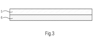
- the device 4 presently comprises two layers 5, 6, with a first layer 5 forming a pressing layer and a second layer 6 forming an insulating layer.
- the pressure layer 5 and the Insulation layer 6 designed as two continuous layers.
- the insulation layer 6 is surrounded on both sides by pressure layers 5 and 5'.
- the pressure layer 5 is surrounded on both sides by insulating layers 6 and 6'.
- the pressure layer surrounds the insulating layer 6 along two end faces.
- the insulation layer 6 is embedded in the pressure layer 5.
- FIG 8 shows the in figure 6 Device 4 shown, the contact pressure layer 5 of the device being deformed by a change in volume of the storage cells 3 . In doing so, primarily the pressing layer 5 is deformed. Because of its design, this layer 5 is only of secondary relevance for the thermal insulation; its compression does not lead to a deterioration in the thermal properties of the device 4.
- the insulation layer 6, on the other hand, is not compressed during deformation, or is compressed only to a minor extent. As a result, the insulation layer 6 retains its thermal insulation capacity even with a pressed system.
- the contact pressure layer 5 consists of a silicone-based foam.
- the insulation layer 6 consists of a non-woven fabric made primarily of inorganic fibers with a filling of inorganic insulation elements, here aerogels. In alternative configurations, inorganic hollow spheres or porous inorganic particles can also be used.
- figure 9 shows that in figure 1 Energy storage system 1 shown, the contact pressure layer 5 of the device being deformed by a change in volume of the storage cells 3 .
- the deformation takes place here by deformable structural elements 7 formed from the pressure layer 5.
- the pressure layer 5 consists of a mechanically robust solid material, here a silicone elastomer.
- the deformable structural elements 7 come into a compressed state 7 ′, so that the pressure layer 5 can absorb the volumetric expansion of the storage cells 3 .
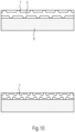
- figure 10 shows a further embodiment of the device 4, the pressure layer 5 being deformed by the volume change of the storage cells 3.
- the deformation takes place here by deformable structural elements 7 of the pressure layer 5.
- the complete structure of the pressure layer 5 is deformed.
- FIG 11 shows the device 4 according to FIG figure 6 , A reinforcement layer 8 being arranged between the pressure layer 5 and the insulation layer 6 .
- the reinforcing sheet 8 is a solid sheet and is made of an inorganic material.
- the inorganic material can be ceramic, graphite or metal or a thermoset.
- the pressure layer 5 deforms, it distributes the compression over the surface of the device 4.
- the reinforcement layer 8 distributes heat in the plane of the device 4.
- figures 12 and 13 each show a device 4 according to FIG figure 9 , A reinforcement layer 8 being arranged between the pressure layer 5 and the insulation layer 6 .
- the reinforcement layer 8 is arranged between the pressure layer 5 and the insulation layer 6 .
- the reinforcement layer 8 distributes the pressure inhomogeneities that occur as a result of the deformation of the pressure layer 5 and are caused by the deformable structural elements 7 .
- the pressure on the insulation layer 6 is largely evenly distributed by the reinforcement layer 8 . This protects the insulating layer 6 from local pressure peaks.
- the deformable structural elements 7 can face away from the insulation layer 6 ( figure 12 ) or directed towards the insulating layer 6 ( figure 13 ).
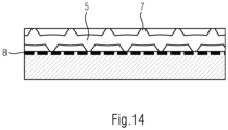
- figure 14 shows a device according to figure 10 , A reinforcement layer 8 being arranged between the pressure layer 5 and the insulation layer 6 .
- the reinforcing sheet 8 is a solid sheet and is made of an inorganic material.
- the inorganic material can be ceramic, graphite or metal or a thermoset.
- the pressure layer 5 deforms, it distributes the compression over the surface of the device 4.
- the reinforcement layer 8 distributes heat in the plane of the device 4.
- FIG figures 15 and 16 each show a device 4 according to FIG figure 9 , wherein two pressure layers 5 are provided, which surround the insulating layer 6 areally.
- the pressure layers 5 additionally surround the insulating layer 6 on two end faces surround ( figure 15 ).
- This arrangement allows the use of insulating layers 6, from which particles can be released due to the design.
- two press-on layers 5 cover the insulating layer 6 over a large area. This version is easy to produce.
- Figures 17 to 19 show devices 4 in which the insulation layer 6 is surrounded by the pressure layer 5 only on the end faces or in the manner of a frame. These designs allow the use of less pressure-resistant insulation layers 6.
- the pressure layer 5 can have deformable structural elements 7.
- the deformable structural elements 7 are made of a silicone elastomer. In the completely deformed state, the thickness of the pressure layer 5 forming a frame is still greater than the thickness of the insulating layer 6.
- Recesses 9 are provided, into which the deformable structural elements 7 can insert. In the completely deformed state, the thickness of the pressing layer 5 forming a frame is approximately as high as that of the insulating layer 6.
- further recesses 10 are provided, into which in particular a soft silicone material can be pressed.
- the thickness of the frame of the pressure layer 5 in the fully deformed state corresponds to the thickness of the insulation layer 6.
- the deformability of the pressure layer can be adapted to the mechanical properties of the insulation layer 6 . Due to the comparatively small contact surface of the pressure layer 5, relatively hard materials can be used since the resulting forces on the pressure layer 5 are high. On the other hand, insulation layers 6 that are particularly easily deformable can also be used as a result.
- figure 20 shows explanations in the Figures 17 to 19 shown device 4, in which the pressure layer 5 surrounds the insulating layer 6 on all sides along the edges.
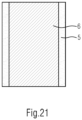
- figure 21 shows explanations in the Figures 17 to 19 shown device 4, in which the pressure layer 5 surrounds the insulation layer 6 along two opposite edges.
- Figures 22 to 24 show a device 4 in which the insulating layer 6 is surrounded on the face side or circumferentially by a further frame element 11.
- the frame element 11 has approximately the same thickness as the insulating layer 6.
- the frame element 11 can be made of a harder material, for example a high-strength silicone elastomer. As a result, the insulation layer 6 is protected against deformation even under high mechanical forces.
- FIG. 12 shows a device 4 in which the insulation layer 6 is covered by a cover layer 12.
- the covering layer 12 ensures that no particles are released from the insulating layer 6 during assembly and during operation of the device 4 . Due to the presence of such a covering layer 12, materials which contain little binder can also be used for the insulating layer 6.
- FIG figures 26 and 27 show further versions of the device 4.
- An outer adhesive tape 13 is applied to the insulation layer 6, which both protects the insulation layer 6 and can be used to assemble the device 4 on the housing of the storage cell 3.
- the insulation layer 6 also contains an inner adhesive layer 14. This is used for the upstream assembly of the pressure layer 5 and the insulation layer 6. As a result, two layers which are optimized per se can be produced and these can be combined in a lamination process, for example.
Landscapes
- Chemical & Material Sciences (AREA)
- Chemical Kinetics & Catalysis (AREA)
- Electrochemistry (AREA)
- General Chemical & Material Sciences (AREA)
- Engineering & Computer Science (AREA)
- Manufacturing & Machinery (AREA)
- Aviation & Aerospace Engineering (AREA)
- Inorganic Chemistry (AREA)
- Secondary Cells (AREA)
- Battery Mounting, Suspending (AREA)
- Thermal Insulation (AREA)
Abstract
Description
- Die Erfindung betrifft ein Energiespeichersystem, umfassend ein Gehäuse, in welchem mehrere Speicherzellen angeordnet sind, wobei die Speicherzellen mittels einer zwischen den Speicherzellen angeordneten Einrichtung voneinander getrennt sind, wobei die Einrichtung zumindest zwei Lagen aufweist.
- Ein derartiges Energiespeichersystem ist aus der
DE 10 2018 113 185 A1 bekannt. Energiespeichersysteme, insbesondere wiederaufladbare Speicher für elektrische Energie, sind vor allem in mobilen Systemen weit verbreitet. Wiederaufladbare Speicher für elektrische Energie werden beispielsweise in tragbaren elektronischen Geräten wie Smartphones oder Laptops eingesetzt. Des Weiteren werden wiederaufladbare Speicher für elektrische Energie vermehrt zum Bereitstellen von Energie für elektrisch angetriebene Fahrzeuge eingesetzt. Dabei ist eine große Bandbreite elektrisch angetriebener Fahrzeuge denkbar, neben Personenkraftwagen beispielsweise auch Zweiräder, Kleintransporter oder Lastkraftwagen. Anwendungen in Robotern, Schiffen, Flugzeugen und mobilen Arbeitsmaschinen sind ebenfalls denkbar. Weitere Einsatzgebiete von elektrischen Energiespeichersystemen sind stationäre Anwendungen, beispielsweise in Backup-Systemen, in Netzwerkstabilisierungssystemen und zur Speicherung elektrischer Energie aus erneuerbaren Energiequellen. - Ein häufig eingesetztes Energiespeichersystem ist dabei ein wiederaufladbarer Speicher in Form eines Lithium-Ionen-Akkumulators. Lithium-Ionen-Akkumulatoren weisen, wie andere wiederaufladbare Speicher für elektrische Energie auch, zumeist mehrere Speicherzellen auf, welche gemeinsam in einem Gehäuse verbaut sind.
- Mehrere elektrisch miteinander verbundene Speicherzellen werden dabei meist zu einem Modul zusammengefasst.
- Dabei erstreckt sich das Energiespeichersystem nicht nur auf Lithium-Ionen-Akkumulatoren. Auch andere wiederaufladbare Batterie-Systeme wie Lithium-Schwefel-Batterien, Feststoff-Batterien, Natrium-Ionen-Batterien oder Metall-Luft-Batterien sind denkbare Energiespeichersysteme. Des Weiteren kommen auch Superkondensatoren als Energiespeichersystem in Betracht.
- Energiespeichersysteme in Form von wiederaufladbaren Speichern weisen die höchste elektrische Kapazität sowie die beste Leistungsaufnahme und -abgabe nur in einem begrenzten Temperaturspektrum auf. Bei Über- bzw. Unterschreiten des optimalen Betriebstemperaturbereichs fallen die Kapazität, die Leistungsaufnahmefähigkeit und die Leistungsabgabefähigkeit des Speichers stark ab und die Funktionalität des Energiespeichers ist beeinträchtigt. Zu hohe Temperaturen können darüber hinaus den Energiespeicher irreversibel schädigen. Demnach sollen sowohl dauerhaft auftretende erhöhte Temperaturen als auch kurzfristige Temperaturspitzen unbedingt vermieden werden. Bei Lithium-Ionen-Akkumulatoren sollen beispielsweise dauerhaft Temperaturen von mehr als 50 °C und kurzfristige Temperaturspitzen von mehr als 80 °C nicht überschritten werden.
- Insbesondere bei Anwendungen in Personenkraftwagen wird eine Schnellladefähigkeit der Energiespeichersysteme gefordert. Dabei sollen die ein Energiespeichersystem bildenden Akkumulatoren innerhalb kurzer Zeit, beispielsweise innerhalb von 15 Minuten vollständig oder nahezu vollständig geladen werden. Aufgrund des Wirkungsgrades des Ladesystems von etwa 90 % bis 95 % werden während des Ladevorgangs im Energiespeichersystem große Wärmemengen freigesetzt, welche aus dem Energiespeichersystem abgeführt werden müssen. Diese Wärmemengen werden im normalen Betriebszustand nicht freigesetzt. Daher ist es erforderlich, das Kühlsystem des Energiespeichersystems so auszulegen, dass die beim Ladevorgang auftretende Wärmemenge aufgenommen werden kann.
- Zu hohe Temperaturen können zu einer irreversiblen Schädigung des Energiespeichersystems führen. In diesem Zusammenhang ist insbesondere bei Lithium-Ionen-Zellen das sogenannte thermische Durchgehen ("thermal runaway") bekannt. Dabei werden in kurzer Zeit hohe thermische Energiemengen sowie gasförmige Abbauprodukte frei, woraus ein hoher Druck und hohe Temperaturen im Gehäuse resultieren. Dieser Effekt ist insbesondere problematisch bei Energiespeichersystemen mit hoher Energiedichte, wie sie beispielsweise zur Bereitstellung elektrischer Energie in elektrisch angetriebenen Fahrzeugen erforderlich ist. Durch zunehmende Energiemengen der einzelnen Zellen und Erhöhung der Packungsdichte der in dem Gehäuse angeordneten Zellen vergrößert sich die Problematik des thermischen Durchgehens.
- Im Bereich einer durchgehenden Zelle können an der Gehäusewand der Zelle über eine Zeitdauer von mehreren Minuten Temperaturen im Bereich von 600 °C bis 1.000 °C entstehen. Die Einrichtung zum thermischen Isolieren muss einer derartigen Beanspruchung standhalten und den Energieübergang auf Nachbarzellen so reduzieren, dass die Temperaturbelastung der Nachbarzellen lediglich höchstens 150 °C beträgt. Wesentlich ist die Begrenzung der Energieübertragung auf Nachbarzellen, um zu verhindern, dass auch diese thermisch durchgehen.
- Insbesondere auf dem Gebiet der Elektromobilität besteht ein Bedürfnis, auf geringem Raum eine hohe Energiedichte zu erzielen, was jedoch den zur Verfügung stehenden Raum für die Isolation der Zellen beschränkt. Um zu verhindern, dass einzelne Speicherzellen einer zu hohen thermischen Belastung ausgesetzt sind, ist es auch erforderlich, von der Speicherzelle freigesetzte Wärme abzuführen. Dementsprechend ist es zumeist nicht ausreichend, Speicherzellen lediglich zu isolieren.
- Über die Lebensdauer betrachtet sind Lithium-Ionen-Akkumulatoren einer Volumenänderung unterworfen, wobei das Volumen mit steigender Lebensdauer zunimmt. Bei Pouch-Zellen macht sich dies beispielsweise durch Ausbauchen bemerkbar. Hinzu kommt eine zyklische Volumenänderung bei jedem Lade- bzw. Entladevorgang. Die Volumenänderung der Speicherzellen muss durch die Einrichtung kompensiert werden. Entweder erfolgt dies durch ein Verspannen der Speicherzellen untereinander, was mit einem sehr großen Druckanstieg verbunden ist. Alternativ werden Kompressionselemente zwischen den Speicherzellen angeordnet, die Volumenänderungen der Speicherzellen aufnehmen.
- Bei den aus dem Stand der Technik bekannten Einrichtungen verringert sich die thermische Isolierwirkung mit zunehmender Verpressung, zumeist ist die Wärmeübertragung umgekehrt proportional zum Abstand der Speicherzellen.
- Der Erfindung liegt die Aufgabe zugrunde, ein Energiespeichersystem bereitzustellen, welches bei einer hohen Energiedichte eine lange Lebensdauer und eine hohe Betriebssicherheit sicherstellt.
- Diese Aufgabe wird mit den Merkmalen von Anspruch 1 gelöst. Auf vorteilhafte Ausgestaltungen nehmen die Unteransprüche Bezug.
- Das erfindungsgemäße Energiespeichersystem umfasst ein Gehäuse, in welchem mehrere Speicherzellen angeordnet sind, wobei die Speicherzellen mittels einer zwischen den Speicherzellen angeordneten Einrichtung voneinander getrennt sind, wobei die Einrichtung zumindest zwei Lagen aufweist, wobei eine erste Lage eine Anpresslage und eine zweite Lage eine Isolationslage bildet. Dabei ist die zweite Lage vorzugsweise inkompressibel ausgebildet.
- Bei dieser Ausgestaltung ist die Isolationslage auf die thermische Isolierung optimiert, während die Anpresslage auf mechanische Eigenschaften optimiert ist. Die thermische Isolierung kann durch inkompressible Ausgestaltung der Isolationslage verbessert werden.
- Dabei können mehrere erste Lagen und/oder mehrere zweite Lagen vorgesehen sein. Die Gesamtdicke der Einrichtung beträgt vorzugsweise zwischen 0,5 mm und 6 mm. Die Gesamtdicke zwischen 0,5 mm und 6 mm ist dabei vorzugsweise auch dann gegeben, wenn die Einrichtung mit einer Flächenpressung von bis zu 100 kPa beaufschlagt ist. Anpresslage und Isolationslage sind vorzugsweise im Sinne einer Reihenschaltung nebeneinander angeordnet.
- Dabei ist denkbar, dass die Einrichtung neben der Isolationslage und der Anpresslage weitere Lagen umfasst. In diesem Zusammenhang ist denkbar, eine Applizierlage, eine Feuerschutzlage, eine Partikelrückhaltelage und/oder eine Kühlkörperlage vorzusehen. Insgesamt ergibt sich eine Einrichtung, welche optimierte mechanische Eigenschaften aufweist, so dass eine hohe Energiedichte und ein kompaktes Anordnen der Speicherzellen möglich sind, während die Isolationslage thermisch optimiert ist und eine Isolation benachbarter Speicherzellen bewirkt.
- Die Isolationslage kann zusätzlich endotherme Eigenschaften aufweisen. Dabei weist die Isolationslage endotherme Eigenschaften vorzugsweise in einem Temperaturbereich zwischen 150°C und 500 °C auf. Bei dieser Ausgestaltung kann das Anpresselement von den Speicherzellen emittierte Energie aufnehmen, wodurch ein unzulässig hoher Temperaturanstieg in oder an den Speicherzellen vermieden werden kann. Es ist auch denkbar, dass die Anpresslage thermisch leitfähig ausgerüstet ist. Beispielsweise ist es denkbar, Metall-Hydroxyde oder Metall-Carbonate vorzusehen.
- Die Anpresslage kann endotherme Eigenschaften aufweisen. Dadurch, dass die Anpresslage endotherm und/oder wärmeleitend ausgebildet sein kann, kann die Isolationslage auf eine hohe thermische Isolierung ausgelegt sein. Somit kann durch die Isolationslage vermieden werden, dass ein unzulässig hoher Wärmeaustausch zwischen benachbarten Speicherzellen erfolgt. Temperaturspitzen, die beispielsweise bei Schnellladevorgängen auftreten können, können hingegen über die Anpresslage aufgrund der endothermen bzw. wärmeleitenden Ausrüstung abgeführt werden. Die Anpresslage kann endotherm reagierende Materialien enthalten, beispielsweise Metall Hydroxyde oder Metall-Carbonate oder Zitronensäure. Denkbar ist auch, dass die Anpresslage mit Fasern aus endotherm reagierenden Materialien ausgerüstet ist.
- Vorzugsweise weist die Anpresslage einen Wärmeleitkoeffizienten von bis zu 1,5 W/(m·K) auf. Die Isolationslage weist vorzugsweise einen Wärmeleitkoeffizienten von maximal 0,2 W/(m·K) auf.
- Die Anpresslage kann elastisch ausgebildet sein. Dadurch ist es einerseits möglich, dass die Speicherzellen gezielt verpresst werden. Andererseits kann die Anpresslage Volumenänderungen der Speicherzellen aufnehmen. Hierzu ist es denkbar, dass die Anpresslage verformbar ausgestaltet ist. Dies kann beispielsweise durch eine Formgebung der Anpresslage erfolgen. Das Material der Anpresslage kann auch verformbar sein oder die Anpresslage kann verformbare Materialien enthalten. Verformbare Materialien sind beispielsweise Materialien mit einer intrinsischen Porosität aufweisen.
- Vorzugsweise ist die Anpresslage mechanisch verformbar. Besonders bevorzugt ist bei einer Flächenpressung zwischen 30 kPa und 1.500 kPa eine Verformbarkeit von mindestens 50 % gegeben. Das bedeutet, dass sich die Dicke der Anpresslage bei ansteigender Flächenpressung verringert und dabei auf mindestens 50 % der Ausgangsdicke reduzierbar ist.
- Vorzugsweise ist die Isolationslage mechanisch weniger verformbar als die Anpresslage. Besonders bevorzugt ist für die Isolationslage bei einer Flächenpressung zwischen 30 kPa und 1.500 kPa eine Verformbarkeit von höchstens 30 % gegeben. Das bedeutet, dass sich zwar auch die Dicke der Isolationslage bei ansteigender Flächenpressung verringern kann. Die Isolationslage ist dabei aber vorzugsweise nur auf maximal 70 % der Ausgangsdicke reduzierbar. Dadurch bietet die Isolationslage auch bei hoher Verpressung der Einrichtung noch gute thermische Isolationseigenschaften.
- Bei mechanischer Belastung ist die Kompression der Anpresslage vorzugsweise wenigstens doppelt so hoch wie die Kompression der Isolationslage.
- Die Anpresslage kann aus elastischem Werkstoff ausgebildet sein. Insbesondere ist denkbar, dass die Anpresslage aus elastomerem Werkstoff ausgebildet ist.
- Die Anpresslage kann auf einer der Speicherzelle zugewandten Seite strukturiert sein. Die Strukturierung verbessert einerseits die Verformbarkeitseigenschaften der Anpresslage und hat andererseits auch eine thermische Wirkung. Je nach Ausgestaltung der Strukturierung können sich zwischen Speicherzelle und Anpresslage Kanäle ergeben, über die von den Speicherzellen emittierte Wärme abgeführt werden kann. Es ist auch denkbar, dass die Strukturierung eine thermische Isolation bewirkt. Dementsprechend ist denkbar, aus der Anpresslage fluidleitende Strukturen auszubilden. Die fluidleitenden Strukturen ermöglichen es auch, im Falle eines thermischen Durchgehens aus einer Speicherzelle austretende Gase abzuleiten.
- Die Anpresslage kann die Isolationslage entlang der Kanten zumindest teilweise umgeben. Bei dieser Ausgestaltung reicht die Anpresslage zumindest abschnittsweise um die Isolationslage herum. Dabei kann die Anpresslage so ausgebildet sein, dass die Isolationslage in die Anpresslage eingebettet ist.
- Die Isolationslage kann aus porösem Material ausgebildet sein. Poröse Materialien sind beispielsweise Faserwerkstoffe wie Vliesstoffe, polymerbasierte Schäume oder andere schaumartige feste Materialien. Des Weiteren können die porösen Materialien Zeolithe, Aerogele, Pyrobubbles oder gasgefüllte Hohlkugeln umfassen. Weiterhin denkbar ist der Einsatz von Aktivkohle. Die Isolationslage kann auch ein faserbasiertes Flächengebilde sein. Denkbar sind auch schaumbasierte Grundmaterialien, in welche die partikulären Isolationsmaterialien eingebettet sind. Denkbar sind weiterhin Schüttungen pulverförmiger Isolationsmaterialien in vorgesehene Bereiche in der Anpresslage.
- Zwischen Isolationslage und Anpresslage kann eine Verstärkungslage angeordnet sein. Die Verstärkungslage kann aus einer Folie ausgebildet sein und aus Kunststoff, Metall oder Graphit bestehen.
- Die Isolationslage kann teilweise aus anorganischem Material ausgebildet sein. Dabei ist die Isolationslage vorzugsweise inkompressibel, aber elastisch verformbar. Insbesondere ist denkbar, dass die Isolationsschicht faserhaltiges Material umfasst.
- Vorzugsweise ist die Isolationslage so ausgebildet, dass diese bei einer flächigen Druckbeaufschlagung der Einrichtung von 1 MPa eine Porosität von mindestens 40 % aufweist. Die Wärmeleitfähigkeit soll auch bei maximaler Druckbeaufschlagung höchstens 0,15 W/(m·K) betragen. Die Porosität der Isolationslage beträgt im unbelasteten Zustand vorzugsweise mindestens 60 %.
- Der Anteil der anorganischen Materialien in der Isolationslage kann wenigstens 60 Gewichtsprozente betragen. Als anorganische Materialien kommen insbesondere Fasern, Hohlkugeln, Aerogele, hochporöse Partikel und/oder dergleichen in Betracht.
- Die Anpresslage kann aus polymeren Materialien, beispielsweise aus Elastomer, aus thermoplastischem Elastomer, aus Thermoplasten oder Duroplasten bestehen. Die Anpresslage kann aus Metall und/oder Keramik bestehen.
- Einige Ausgestaltungen des erfindungsgemäßen Energiespeichersystems werden nachfolgend anhand der Figuren näher erläutert. Diese zeigen, jeweils schematisch:
- Fig. 1
- ein Energiespeichersystem mit einer Einrichtung;
- Fig. 2
- eine Darstellung des mechanischen Arbeitsbereiches der Einrichtung;
- Fig. 3
- eine Einrichtung gemäß einer ersten Ausgestaltung im Schnitt;
- Fig. 4
- eine Einrichtung gemäß einer zweiten Ausgestaltung im Schnitt;
- Fig. 5
- eine Einrichtung gemäß einer dritten Ausgestaltung im Schnitt;
- Fig. 6
- eine Einrichtung gemäß einer vierten Ausgestaltung im Schnitt;
- Fig. 7
- eine Einrichtung gemäß einer fünften Ausgestaltung im Schnitt;
- Fig. 8
- die Einrichtung gemäß
Fig. 6 in der oberen Darstellung unbelastet, in der unteren Darstellung mechanisch belastet; - Fig. 9
- die Einrichtung gemäß einer sechsten Ausgestaltung in der oberen Darstellung unbelastet, in der unteren Darstellung mechanisch belastet;
- Fig. 10
- die Einrichtung gemäß einer siebten Ausgestaltung in der oberen Darstellung unbelastet, in der unteren Darstellung mechanisch belastet;
- Fig. 11
- die Einrichtung gemäß
Fig. 6 mit einer zusätzlichen Lage in der oberen Darstellung unbelastet, in der unteren Darstellung mechanisch belastet; - Fig. 12
- die Einrichtung gemäß
Fig. 9 mit einer zusätzlichen Lage; - Fig. 13
- die Einrichtung gemäß
Fig. 12 in einer weiteren Ausgestaltung; - Fig. 14
- die Einrichtung gemäß
Fig. 10 mit einer zusätzlichen Lage; - Fig. 15
- die Einrichtung gemäß
Fig. 9 mit beidseitiger Isolationslage, wobei die Isolationslage die Anpresslage allseitig umgibt; - Fig. 16
- die Einrichtung gemäß
Fig. 9 mit beidseitiger Isolationslage, wobei die Isolationslage die Anpresslage entlang der Hauptseiten bedeckt; - Fig. 17
- eine Einrichtung mit Rahmenelement gemäß erster Ausgestaltung;
- Fig. 18
- eine Einrichtung mit Rahmenelement gemäß zweiter Ausgestaltung;
- Fig. 19
- eine Einrichtung mit Rahmenelement gemäß dritter Ausgestaltung;
- Fig. 20
- eine Einrichtung gemäß der
Figuren 17 ,18 oder19 , wobei das Rahmenelement die Einrichtung entlang der Kanten allseitig umgibt; - Fig. 21
- eine Einrichtung gemäß der
Figuren 17 ,18 oder19 , wobei das Rahmenelement die Einrichtung entlang zweier einander gegenüberliegender Kanten bedeckt; - Fig. 22
- eine Einrichtung gemäß
Figur 3 mit zusätzlichem Kantenelement; - Fig. 23
- eine Einrichtung gemäß
Figur 17 mit zusätzlichem Kantenelement; - Fig. 24
- eine Einrichtung gemäß
Figur 16 mit zusätzlichem Kantenelement; - Fig. 25
- eine Einrichtung gemäß
Figur 6 mit einer zusätzlichen Abdecklage, welche bündig mit der Isolationslage abschließt; - Fig. 26
- eine Einrichtung gemäß
Figur 6 mit einer zusätzlichen Klebelage; - Fig. 27
- eine Einrichtung gemäß
Figur 6 mit zwei zusätzlichen Klebelagen. - Die Figuren zeigen ein Energiespeichersystem 1 zum Speichern elektrischer Energie. Vorliegend umfasst das Energiespeichersystem 1 ein Gehäuse 2, in welchem mehrere Speicherzellen 3 in Form von elektrochemischen Akkumulatoren angeordnet sind. Die Speicherzellen 3 sind vorliegend als Lithium-Ionen-Akkumulatoren ausgebildet. In einer alternativen Ausgestaltung können die Speicherzellen 3 als Feststoff-Akkumulator ausgebildet sein. Die Speicherzellen 3 sind in Form von prismatischen Zellen ausgebildet. In alternativen Ausgestaltungen können die Speicherzellen 3 auch als Pouch-Zellen oder Rundzellen ausgebildet sein. Die Speicherzellen 3 sind nebeneinander in dem Gehäuse 2 angeordnet und bilden einen Stack.
- Die Speicherzellen 3 sind mittels einer zwischen den Speicherzellen 3 angeordneten Einrichtung 4 thermisch voneinander getrennt und mechanisch abgestützt. Dabei umfasst die Einrichtung 4 zumindest zwei Lagen 5, 6, wobei eine Lage 5 eine Anpresslage und eine Lage 6 eine Isolationslage bildet.
-
Figur 1 zeigt eine erste Ausgestaltung des zuvor beschriebenen Energiespeichersystems 1. Die zwischen zwei Speicherzellen 3 angeordnete Einrichtung 4 umfasst eine zweite Lage 6, welche inkompressibel ist und eine Isolationslage bildet und beidseitig der zweiten Lage 6 sind erste Lagen 5 angeordnet, welche kompressibel sind und Anpresslagen bilden. - Die Anpresslagen 5 weisen Erhebungen und Einbuchtungen auf. Des Weiteren sind die Anpresslagen 5 aus elastomeren Material ausgebildet. Durch die Strukturierung der Anpresslagen 5 und durch den elastomeren Werkstoff sind die Anpresslagen 5 sehr verformbar ausgestaltet. Die Anpresslagen 5 sind ferner ausgebildet, von den Speicherzellen 3 emittierte Wärme aufzunehmen und abzuführen. Die Isolationslage 6 hingegen bewirkt eine thermische Isolierung benachbarter Speicherzellen 3.
- Bei der vorliegenden Ausgestaltung beträgt die Wärmeleitfähigkeit der Isolationslage 6 0,1 W/(m·K). Die Einrichtung 4 weist eine endotherme Wärmeaufnahme von mindestens 300 kJ/kg auf. Bei der vorliegenden Ausgestaltung beträgt die Dicke der Einrichtung 4 im unbelasteten Zustand 4 mm und in montiertem, verspanntem Zustand 3 mm.
-
Figur 2 zeigt den idealen mechanischen Arbeitsbereich einer Einrichtung 4. Dabei ist zu erkennen, dass das Anschwellen der Speicherzellen 3 - gleichbedeutend mit der Abnahme des Spaltes zwischen den Speicherzellen 3 - im Arbeitsbereich nicht zu einer zu erheblichen Zunahme der mechanischen Kräfte führt. -
Figuren 3 bis 7 zeigen im Detail die Einrichtung 4 des inFigur 1 gezeigten Energiespeichersystems 1. Die Einrichtung 4 umfasst vorliegend zwei Lagen 5, 6, wobei eine erste Lage 5 eine Anpresslage und eine zweite Lage 6 eine Isolationslage bildet. Bei der Ausgestaltung gemäßFigur 3 sind die Anpresslage 5 und die Isolationslage 6 als zwei durchgängige Lagen ausgeführt. Bei der Ausgestaltung gemäßFigur 4 ist die Isolationslage 6 beidseitig von Anpresslagen 5 und 5' umgeben. Bei der Ausgestaltung gemäßFigur 5 ist die Anpresslage 5 beidseitig von Isolationslagen 6 und 6' umgeben. Bei der Ausgestaltung gemäßFigur 6 umgibt die Anpresslage die Isolationslage 6 entlang von zwei Stirnseiten. Bei der Ausgestaltung gemäßFigur 7 ist die Isolationslage 6 in die Anpresslage 5 eingebettet. -
Figur 8 zeigt die inFigur 6 gezeigte Einrichtung 4, wobei die Anpresslage 5 der Einrichtung durch Volumenänderung der Speicherzellen 3 verformt wird. Herbei wird vornehmlich die Anpresslage 5 verformt. Aufgrund ihrer Ausgestaltung ist diese Lage 5 für die thermische Isolation nur untergeordnet relevant, ihre Verpressung führt nicht zu einer Verschlechterung der thermischen Eigenschaften der Einrichtung 4. Die Isolationslage 6 wird hingegen bei Verformung nicht, beziehungsweise nur in untergeordnetem Maße komprimiert. Dadurch behält die Isolationslage 6 ihre thermische Isolationsfähigkeit auch bei einem verpressten System. In dem vorliegendem Ausführungsbeispiel besteht die Anpresslage 5 aus einem silikonbasierten Schaum. Die Isolationslage 6 besteht aus einem Vliesstoff aus vorwiegend anorganischen Fasern mit einer Füllung aus anorganischen Isolationselementen, hier aus Aerogelen. In alternativen Ausgestaltungen können auch anorganische Hohlkugeln oder poröse anorganische Partikel zum Einsatz gelangen. -
Figur 9 zeigt das inFigur 1 gezeigte Energiespeichersystem 1, wobei die Anpresslage 5 der Einrichtung durch Volumenänderung der Speicherzellen 3 verformt wird. Die Verformung erfolgt hierbei durch aus der Anpresslage 5 ausgebildete, verformbare Strukturelemente 7. In dieser Ausführung besteht die Anpresslage 5 aus einem mechanisch robusten Vollmaterial, hier einem Silikon-Elastomer. Bei mechanischer Belastung legen sich die verformbaren Strukturelemente 7 zu einem verpressten Zustand 7' an, so dass die Anpresslage 5 die Volumenausdehnung der Speicherzellen 3 aufnehmen kann. -
Figur 10 zeigt eine weitere Ausgestaltung der Einrichtung 4, wobei die Anpresslage 5 durch Volumenänderung der Speicherzellen 3 verformt wird. Die Verformung erfolgt hier durch verformbare Strukturelemente 7 der Anpresslage 5. In diesem Fall wird die komplette Struktur der Anpresslage 5 verformt. -
Figur 11 zeigt die Einrichtung 4 gemäßFigur 6 , wobei zwischen Anpresslage 5 und Isolationslage 6 eine Verstärkungslage 8 angeordnet ist. Die Verstärkungslage 8 ist eine feste Lage und besteht aus einem anorganischen Material. Das anorganische Material kann Keramik, Graphit oder Metall oder ein Duroplast sein. Bei Verformung der Anpresslage 5 verteilt sie die Verpressung über die Fläche der Einrichtung 4. Zusätzlich verteilt die Verstärkungslage 8 Wärme in der Ebene der Einrichtung 4. -
Figuren 12 und13 zeigen jeweils eine Einrichtung 4 gemäßFigur 9 , wobei zwischen Anpresslage 5 und Isolationslage 6 eine Verstärkungslage 8 angeordnet ist. Die Verstärkungslage 8 ist zwischen der Anpresslage 5 und der Isolationslage 6 angeordnet. Die Verstärkungslage 8 verteilt die durch die Deformation der Anpresslage 5 auftretenden Druckinhomogenitäten, welche durch die verformbaren Strukturelemente 7 hervorgerufen werden. Durch die Verstärkungslage 8 ist der Druck auf die Isolationslage 6 weitgehend gleich verteilt. Dies schützt die Isolationslage 6 vor lokalen Druckspitzen. Die verformbaren Strukturelemente 7 können dabei von der Isolationslage 6 abgewandt (Figur 12 ) oder zu der Isolationslage 6 gerichtet sein (Figur 13 ). -
Figur 14 zeigt eine Einrichtung gemäßFigur 10 , wobei zwischen Anpresslage 5 und Isolationslage 6 eine Verstärkungslage 8 angeordnet ist. Die Verstärkungslage 8 ist eine feste Lage und besteht aus einem anorganischen Material. Das anorganische Material kann Keramik, Graphit oder Metall oder ein Duroplast sein. Bei Verformung der Anpresslage 5 verteilt sie die Verpressung über die Fläche der Einrichtung 4. Zusätzlich verteilt die Verstärkungslage 8 Wärme in der Ebene der Einrichtung 4. -
Figuren 15 und16 zeigen jeweils eine Einrichtung 4 gemäßFigur 9 , wobei zwei Anpresslagen 5 vorgesehen sind, die die Isolationslage 6 flächig umgeben. Die Anpresslagen 5 umgeben dabei die Isolationslage 6 zusätzlich an zwei Stirnflächen umgeben (Figur 15 ). Diese Anordnung erlaubt den Einsatz von Isolationslagen 6, aus welchen bauartbedingt Partikel freigesetzt werden können. Bei der Ausgestaltung gemäßFigur 16 decken zwei Anpresslagen 5 die Isolationslage 6 flächig ab. Diese Ausführung ist einfach herstellbar. -
Figuren 17 bis 19 zeigen Einrichtungen 4, bei denen die Isolationslage 6 lediglich an den Stirnseiten oder rahmenartig von der Anpresslage 5 umgeben sind. Diese Ausführungen erlauben den Einsatz von weniger druckstabilen Isolationslagen 6. Die Anpresslage 5 kann dabei verformbare Strukturelemente 7 aufweisen. Bei der Ausgestaltung gemäßFigur 17 sind die verformbare Strukturelemente 7 aus einem Silikon-Elastomer ausgeführt. Im komplett verformten Zustand ist die Dicke der einen Rahmen formenden Anpresslage 5 immer noch größer als die Dicke der Isolationslage 6. Bei der Ausgestaltung gemäßFigur 18 sind Aussparungen 9 vorgesehen, in welche sich die verformbaren Strukturelemente 7 einlegen können. Die Dicke der einen Rahmen formenden Anpresslage 5 ist im komplett verformten Zustand in etwa so hoch wie die der Isolationslage 6. Bei der Ausgestaltung gemäßFigur 19 sind weitere Aussparungen 10 vorgesehen, in welche insbesondere ein weiches Silikonmaterial verpresst werden kann. Auch hier entspricht die Dicke des Rahmens der Anpresslage 5 im komplett verformten Zustand der Dicke der Isolationslage 6. - In allen Ausführungen kann die Verformbarkeit der Anpresslage den mechanischen Eigenschaften der Isolationslage 6 angepasst werden. Aufgrund der vergleichsweise geringen Auflagefläche der Anpresslage 5 können relativ harte Materialien eingesetzt werden, da die resultierenden Kräfte auf die Anpresslage 5 hoch sind. Auf der anderen Seite können dadurch auch besonders leicht verformbare Isolationslagen 6 genutzt werden.
-
Figur 20 zeigt Ausführungen der in denFiguren 17 bis 19 gezeigten Einrichtung 4, bei welcher die Anpresslage 5 die Isolationslage 6 entlang der Kanten allseitig umgibt.Figur 21 zeigt Ausführungen der in denFiguren 17 bis 19 gezeigten Einrichtung 4, bei welcher die Anpresslage 5 die Isolationslage 6 entlang von zwei einander gegenüberliegenden Kanten umgibt. -
Figuren 22 bis 24 zeigen eine Einrichtung 4, in welcher die Isolationslage 6 stirnseitig oder umfänglich von einem weiteren Rahmenelement 11 umgeben ist. Das Rahmenelement 11 hat hierbei in etwa die Dicke der Isolationslage 6. Das Rahmenelement 11 kann hierbei aus einem härteren Werkstoff bestehen, beispielsweise einem hoch-shorigen Silikon-Elastomer. Dadurch wird die Isolationslage 6 auch bei hohen mechanischen Kräften vor einer Deformation geschützt. -
Figur 25 stellt eine Einrichtung 4 dar, bei der die Isolationslage 6 von einer Abdecklage 12 bedeckt ist. Die Abdecklage 12 stellt sicher, dass bei der Montage und im Betrieb der Einrichtung 4 keine Partikel aus der Isolationslage 6 freigesetzt werden. Durch Vorhandensein einer solchen Abdecklage 12 können für die Isolationslage 6 auch Materialien verwendet werden, die wenig Binder enthalten. Es ist auch der Einsatz von Partikelschüttungen, z.B. aus Aerogelen, Hohlkugeln oder ultra-porösen Füllstoffen denkbar. -
Figuren 26 und27 zeigen weitere Ausführungen der Einrichtung 4. Bei der Ausgestaltung gemäßFigur 26 ist auf der Isolationslage 6 ein äußeres Klebeband 13 appliziert, welches sowohl die Isolationslage 6 schützt als auch zur Assemblierung der Einrichtung 4 auf das Gehäuse der Speicherzelle 3 genutzt werden kann. - Bei der Ausgestaltung gemäß
Figur 27 enthält die Isolationslage 6 zudem eine innere Klebeschicht 14. Diese dient der vorgeschalteten Assemblierung der Anpresslage 5 und der Isolationslage 6. Dadurch können zwei in sich optimierte Lagen hergestellt werden und diese beispielsweise in einem Laminierungsprozess vereint werden.
Claims (16)
- Energiespeichersystem (1), umfassend ein Gehäuse (2), in welchem mehrere Speicherzellen (3) angeordnet sind, wobei die Speicherzellen (3) mittels einer zwischen den Speicherzellen (3) angeordneten Einrichtung (4) voneinander getrennt sind, wobei die Einrichtung (4) zumindest zwei Lagen (5, 6) aufweist, dadurch gekennzeichnet, dass eine erste Lage (5) eine Anpresslage und eine zweite Lage (6) eine Isolationslage bildet.
- Energiespeichersystem nach Anspruch 1, dadurch gekennzeichnet, dass die Anpresslage elastisch ausgebildet ist.
- Energiespeichersystem nach Anspruch 1 oder 2, dadurch gekennzeichnet, dass die Anpresslage verformbar ausgestaltet ist.
- Energiespeichersystem nach einem der Ansprüche 1 bis 3, dadurch gekennzeichnet, dass die Anpresslage aus elastischem Werkstoff ausgebildet ist.
- Energiespeichersystem nach einem der Ansprüche 1 bis 4, dadurch gekennzeichnet, dass die Anpresslage zumindest auf einer einer Speicherzelle (3) zugewandten Seite strukturiert ist.
- Energiespeichersystem nach einem der Ansprüche 1 bis 5, dadurch gekennzeichnet, dass die Anpresslage die Isolationslage entlang der Kanten zumindest abschnittsweise umgibt.
- Energiespeichersystem nach Anspruch 6, dadurch gekennzeichnet, dass die Anpresslage benachbarte Speicherzellen (3) kontaktiert.
- Energiespeichersystem nach Anspruch 6 oder 7, dadurch gekennzeichnet, dass die Isolationslage in die Anpresslage eingebettet ist.
- Energiespeichersystem nach einem der Ansprüche 1 bis 8, dadurch gekennzeichnet, dass aus der Anpresslage fluidleitende Strukturen ausgebildet sind.
- Energiespeichersystem nach einem der Ansprüche 1 bis 9, dadurch gekennzeichnet, dass die Isolationslage inkompressibel ausgestaltet ist.
- Energiespeichersystem nach einem der Ansprüche 1 bis 10, dadurch gekennzeichnet, dass die Isolationslage aus porösem Material ausgebildet ist.
- Energiespeichersystem nach einem der Ansprüche 1 bis 11, dadurch gekennzeichnet, dass die Isolationsschicht zumindest teilweise aus anorganischem Material ausgebildet ist.
- Energiespeichersystem nach einem der Ansprüche 1 bis 12, dadurch gekennzeichnet, dass die Isolationsschicht faserhaltiges Material umfasst.
- Energiespeichersystem nach einem der Ansprüche 1 bis 13, dadurch gekennzeichnet, dass die Isolationsschicht thermisch isolierende Partikel umfasst.
- Energiespeichersystem nach Anspruch 14, dadurch gekennzeichnet, dass die thermisch isolierenden Partikel Hohlkugeln, hochporöse Partikel und/oder Aerogele umfassen.
- Energiespeichersystem nach einem der Ansprüche 1 bis 15, dadurch gekennzeichnet, dass zwischen Anpresslage und Isolationslage eine Verstärkungslage angeordnet ist.
Applications Claiming Priority (1)
| Application Number | Priority Date | Filing Date | Title |
|---|---|---|---|
| DE102021132072.0A DE102021132072A1 (de) | 2021-12-06 | 2021-12-06 | Energiespeichersystem |
Publications (1)
| Publication Number | Publication Date |
|---|---|
| EP4191753A1 true EP4191753A1 (de) | 2023-06-07 |
Family
ID=84387687
Family Applications (1)
| Application Number | Title | Priority Date | Filing Date |
|---|---|---|---|
| EP22211156.9A Pending EP4191753A1 (de) | 2021-12-06 | 2022-12-02 | Energiespeichersystem |
Country Status (6)
| Country | Link |
|---|---|
| US (1) | US20230335826A1 (de) |
| EP (1) | EP4191753A1 (de) |
| JP (1) | JP7560526B2 (de) |
| KR (1) | KR102873734B1 (de) |
| CN (1) | CN116315412A (de) |
| DE (1) | DE102021132072A1 (de) |
Families Citing this family (4)
| Publication number | Priority date | Publication date | Assignee | Title |
|---|---|---|---|---|
| JP2025034691A (ja) * | 2023-08-31 | 2025-03-13 | イビデン株式会社 | 防炎シート及びその製造方法、並びに組電池 |
| JP7641340B1 (ja) * | 2023-09-21 | 2025-03-06 | 住友理工株式会社 | バッテリーパック用断熱材およびその製造方法 |
| DE102023128449A1 (de) | 2023-10-17 | 2025-04-17 | Carl Freudenberg Kg | Schichtmaterial zur thermischen Isolation |
| JP2026001609A (ja) * | 2024-06-19 | 2026-01-07 | トヨタ自動車株式会社 | 電池スタック、蓄電装置及び車両搭載構造。 |
Citations (6)
| Publication number | Priority date | Publication date | Assignee | Title |
|---|---|---|---|---|
| DE102018113185A1 (de) | 2017-06-08 | 2018-12-13 | Toyota Jidosha Kabushiki Kaisha | Brennstoffzellenfahrzeug |
| JP2018206605A (ja) * | 2017-06-05 | 2018-12-27 | 積水化学工業株式会社 | 熱暴走防止シート |
| EP3641006A1 (de) * | 2018-08-31 | 2020-04-22 | Contemporary Amperex Technology Co., Limited | Batteriemodul |
| US20200290933A1 (en) * | 2017-11-30 | 2020-09-17 | Mitsubishi Chemical Corporation | Partition member and assembled battery |
| US20200343495A1 (en) * | 2017-08-29 | 2020-10-29 | Carl Freudenberg Kg | Energy storage system |
| US20210288362A1 (en) * | 2020-03-12 | 2021-09-16 | Rogers Corporation | Thermal management multilayer sheet for a battery |
Family Cites Families (5)
| Publication number | Priority date | Publication date | Assignee | Title |
|---|---|---|---|---|
| CN102640347B (zh) * | 2009-12-07 | 2015-12-02 | 住友重机械工业株式会社 | 挖土机 |
| DE102018000421A1 (de) * | 2017-12-21 | 2019-06-27 | H.K.O. Isolier- Und Textiltechnik Gmbh | Mehrschichtiges Wärmedämmelement für Batterien |
| EP3847715B1 (de) * | 2018-09-07 | 2026-04-15 | 3M Innovative Properties Company | Feuerschutzartikel und zugehörige verfahren |
| CN216413148U (zh) * | 2020-02-18 | 2022-04-29 | 罗杰斯公司 | 热管理多层片、电池及电池组件 |
| EP4386122B1 (de) | 2020-07-30 | 2025-11-05 | 3M Innovative Properties Co. | Barriere gegen thermisches durchgehen für eine batterie |
-
2021
- 2021-12-06 DE DE102021132072.0A patent/DE102021132072A1/de active Pending
-
2022
- 2022-11-21 KR KR1020220156394A patent/KR102873734B1/ko active Active
- 2022-12-02 EP EP22211156.9A patent/EP4191753A1/de active Pending
- 2022-12-02 CN CN202211539462.1A patent/CN116315412A/zh active Pending
- 2022-12-05 JP JP2022194015A patent/JP7560526B2/ja active Active
- 2022-12-05 US US18/074,535 patent/US20230335826A1/en active Pending
Patent Citations (6)
| Publication number | Priority date | Publication date | Assignee | Title |
|---|---|---|---|---|
| JP2018206605A (ja) * | 2017-06-05 | 2018-12-27 | 積水化学工業株式会社 | 熱暴走防止シート |
| DE102018113185A1 (de) | 2017-06-08 | 2018-12-13 | Toyota Jidosha Kabushiki Kaisha | Brennstoffzellenfahrzeug |
| US20200343495A1 (en) * | 2017-08-29 | 2020-10-29 | Carl Freudenberg Kg | Energy storage system |
| US20200290933A1 (en) * | 2017-11-30 | 2020-09-17 | Mitsubishi Chemical Corporation | Partition member and assembled battery |
| EP3641006A1 (de) * | 2018-08-31 | 2020-04-22 | Contemporary Amperex Technology Co., Limited | Batteriemodul |
| US20210288362A1 (en) * | 2020-03-12 | 2021-09-16 | Rogers Corporation | Thermal management multilayer sheet for a battery |
Also Published As
| Publication number | Publication date |
|---|---|
| JP7560526B2 (ja) | 2024-10-02 |
| DE102021132072A1 (de) | 2023-06-07 |
| KR102873734B1 (ko) | 2025-10-17 |
| KR20230085077A (ko) | 2023-06-13 |
| US20230335826A1 (en) | 2023-10-19 |
| CN116315412A (zh) | 2023-06-23 |
| JP2023084120A (ja) | 2023-06-16 |
Similar Documents
| Publication | Publication Date | Title |
|---|---|---|
| EP4191753A1 (de) | Energiespeichersystem | |
| EP3676890B1 (de) | Energiespeichersystem | |
| DE102018113815B4 (de) | Energiespeichersystem | |
| EP4014275A1 (de) | Energiespeichersystem | |
| EP3118910B1 (de) | Aufnahmeelement für pouch-zellen | |
| WO2020221856A1 (de) | Druckmodul, insbesondere für lithiumionen-batteriezellen | |
| DE102018000421A1 (de) | Mehrschichtiges Wärmedämmelement für Batterien | |
| DE102021118437B3 (de) | Thermische Isolationsmatte für Batteriesysteme | |
| WO2021028189A1 (de) | Energiespeichersystem | |
| EP3582290A1 (de) | Lasttragendes batteriemodul für ein kraftfahrzeug und kraftfahrzeug | |
| WO2021249971A1 (de) | Energiespeichersystem | |
| WO2015114074A1 (de) | Galvanische batteriezelle, insbesondere wiederaufladbare lithium-schwefel-batteriezelle, mit volumenausgleichselement | |
| DE102021124831A1 (de) | Batterieanordnung und Kraftfahrzeug | |
| DE102012224330A1 (de) | Elektrische Akkumulatorvorrichtung mit elastischen Elementen | |
| DE102015008264A1 (de) | Batterie für ein Kraftfahrzeug und Kraftfahrzeug | |
| WO2011073426A1 (de) | Akkumulator | |
| DE102018108962A1 (de) | Batteriezellenmodul und Kraftfahrzeug mit demselben | |
| WO2024028367A1 (de) | Schutzelement | |
| DE102021210340A1 (de) | Batteriezelle | |
| DE102021132476B3 (de) | Batteriezellenanordnung und Kraftfahrzeug | |
| DE102017001683A1 (de) | Energiespeichersystem | |
| DE102021133321A1 (de) | Energiespeicherzelle | |
| WO2025242382A1 (de) | Zellzwischenlage und verfahren zur herstellung einer zellzwischenlage | |
| WO2024208699A1 (de) | Energiespeicheranordnung | |
| WO2025228970A1 (de) | Batterieanordnung mit verbesserter thermischer isolierung |
Legal Events
| Date | Code | Title | Description |
|---|---|---|---|
| PUAI | Public reference made under article 153(3) epc to a published international application that has entered the european phase |
Free format text: ORIGINAL CODE: 0009012 |
|
| STAA | Information on the status of an ep patent application or granted ep patent |
Free format text: STATUS: THE APPLICATION HAS BEEN PUBLISHED |
|
| AK | Designated contracting states |
Kind code of ref document: A1 Designated state(s): AL AT BE BG CH CY CZ DE DK EE ES FI FR GB GR HR HU IE IS IT LI LT LU LV MC ME MK MT NL NO PL PT RO RS SE SI SK SM TR |
|
| STAA | Information on the status of an ep patent application or granted ep patent |
Free format text: STATUS: REQUEST FOR EXAMINATION WAS MADE |
|
| 17P | Request for examination filed |
Effective date: 20231201 |
|
| RBV | Designated contracting states (corrected) |
Designated state(s): AL AT BE BG CH CY CZ DE DK EE ES FI FR GB GR HR HU IE IS IT LI LT LU LV MC ME MK MT NL NO PL PT RO RS SE SI SK SM TR |
|
| RIN1 | Information on inventor provided before grant (corrected) |
Inventor name: KRITZER, PETER Inventor name: ZUBER, RICHARD Inventor name: LEICHNER, TIM Inventor name: WOLL, DANIELA Inventor name: STRIEFLER, ARMIN Inventor name: MOEHRING, DIRK Inventor name: JEDROWICZ, GRAZYNA Inventor name: MORGENSTERN, STEFAN Inventor name: JOHE, MAIK Inventor name: HEINEMANN, JOACHIM |