EP4191631A1 - Key structure - Google Patents
Key structure Download PDFInfo
- Publication number
- EP4191631A1 EP4191631A1 EP22166093.9A EP22166093A EP4191631A1 EP 4191631 A1 EP4191631 A1 EP 4191631A1 EP 22166093 A EP22166093 A EP 22166093A EP 4191631 A1 EP4191631 A1 EP 4191631A1
- Authority
- EP
- European Patent Office
- Prior art keywords
- board
- pressure sensing
- pressure
- movable
- contact
- Prior art date
- Legal status (The legal status is an assumption and is not a legal conclusion. Google has not performed a legal analysis and makes no representation as to the accuracy of the status listed.)
- Withdrawn
Links
Images



Classifications
-
- H—ELECTRICITY
- H01—ELECTRIC ELEMENTS
- H01H—ELECTRIC SWITCHES; RELAYS; SELECTORS; EMERGENCY PROTECTIVE DEVICES
- H01H13/00—Switches having rectilinearly-movable operating part or parts adapted for pushing or pulling in one direction only, e.g. push-button switch
- H01H13/02—Details
- H01H13/12—Movable parts; Contacts mounted thereon
-
- H—ELECTRICITY
- H01—ELECTRIC ELEMENTS
- H01H—ELECTRIC SWITCHES; RELAYS; SELECTORS; EMERGENCY PROTECTIVE DEVICES
- H01H13/00—Switches having rectilinearly-movable operating part or parts adapted for pushing or pulling in one direction only, e.g. push-button switch
- H01H13/70—Switches having rectilinearly-movable operating part or parts adapted for pushing or pulling in one direction only, e.g. push-button switch having a plurality of operating members associated with different sets of contacts, e.g. keyboard
- H01H13/84—Switches having rectilinearly-movable operating part or parts adapted for pushing or pulling in one direction only, e.g. push-button switch having a plurality of operating members associated with different sets of contacts, e.g. keyboard characterised by ergonomic functions, e.g. for miniature keyboards; characterised by operational sensory functions, e.g. sound feedback
-
- H—ELECTRICITY
- H01—ELECTRIC ELEMENTS
- H01H—ELECTRIC SWITCHES; RELAYS; SELECTORS; EMERGENCY PROTECTIVE DEVICES
- H01H13/00—Switches having rectilinearly-movable operating part or parts adapted for pushing or pulling in one direction only, e.g. push-button switch
- H01H13/02—Details
- H01H13/12—Movable parts; Contacts mounted thereon
- H01H13/14—Operating parts, e.g. push-button
-
- H—ELECTRICITY
- H01—ELECTRIC ELEMENTS
- H01H—ELECTRIC SWITCHES; RELAYS; SELECTORS; EMERGENCY PROTECTIVE DEVICES
- H01H13/00—Switches having rectilinearly-movable operating part or parts adapted for pushing or pulling in one direction only, e.g. push-button switch
- H01H13/02—Details
-
- H—ELECTRICITY
- H01—ELECTRIC ELEMENTS
- H01H—ELECTRIC SWITCHES; RELAYS; SELECTORS; EMERGENCY PROTECTIVE DEVICES
- H01H13/00—Switches having rectilinearly-movable operating part or parts adapted for pushing or pulling in one direction only, e.g. push-button switch
- H01H13/02—Details
- H01H13/10—Bases; Stationary contacts mounted thereon
-
- H—ELECTRICITY
- H01—ELECTRIC ELEMENTS
- H01H—ELECTRIC SWITCHES; RELAYS; SELECTORS; EMERGENCY PROTECTIVE DEVICES
- H01H13/00—Switches having rectilinearly-movable operating part or parts adapted for pushing or pulling in one direction only, e.g. push-button switch
- H01H13/02—Details
- H01H13/12—Movable parts; Contacts mounted thereon
- H01H13/20—Driving mechanisms
-
- H—ELECTRICITY
- H01—ELECTRIC ELEMENTS
- H01H—ELECTRIC SWITCHES; RELAYS; SELECTORS; EMERGENCY PROTECTIVE DEVICES
- H01H13/00—Switches having rectilinearly-movable operating part or parts adapted for pushing or pulling in one direction only, e.g. push-button switch
- H01H13/70—Switches having rectilinearly-movable operating part or parts adapted for pushing or pulling in one direction only, e.g. push-button switch having a plurality of operating members associated with different sets of contacts, e.g. keyboard
- H01H13/702—Switches having rectilinearly-movable operating part or parts adapted for pushing or pulling in one direction only, e.g. push-button switch having a plurality of operating members associated with different sets of contacts, e.g. keyboard with contacts carried by or formed from layers in a multilayer structure, e.g. membrane switches
- H01H13/705—Switches having rectilinearly-movable operating part or parts adapted for pushing or pulling in one direction only, e.g. push-button switch having a plurality of operating members associated with different sets of contacts, e.g. keyboard with contacts carried by or formed from layers in a multilayer structure, e.g. membrane switches characterised by construction, mounting or arrangement of operating parts, e.g. push-buttons or keys
-
- H—ELECTRICITY
- H01—ELECTRIC ELEMENTS
- H01H—ELECTRIC SWITCHES; RELAYS; SELECTORS; EMERGENCY PROTECTIVE DEVICES
- H01H9/00—Details of switching devices, not covered by groups H01H1/00 - H01H7/00
- H01H9/16—Indicators for switching condition, e.g. "on" or "off"
-
- H—ELECTRICITY
- H01—ELECTRIC ELEMENTS
- H01H—ELECTRIC SWITCHES; RELAYS; SELECTORS; EMERGENCY PROTECTIVE DEVICES
- H01H2207/00—Connections
- H01H2207/026—Pressure contact
-
- H—ELECTRICITY
- H01—ELECTRIC ELEMENTS
- H01H—ELECTRIC SWITCHES; RELAYS; SELECTORS; EMERGENCY PROTECTIVE DEVICES
- H01H2211/00—Spacers
- H01H2211/026—Spacers without separate element
- H01H2211/032—Pressure sensitive layer on contacts
-
- H—ELECTRICITY
- H01—ELECTRIC ELEMENTS
- H01H—ELECTRIC SWITCHES; RELAYS; SELECTORS; EMERGENCY PROTECTIVE DEVICES
- H01H2233/00—Key modules
- H01H2233/07—Cap or button on actuator part
-
- Y—GENERAL TAGGING OF NEW TECHNOLOGICAL DEVELOPMENTS; GENERAL TAGGING OF CROSS-SECTIONAL TECHNOLOGIES SPANNING OVER SEVERAL SECTIONS OF THE IPC; TECHNICAL SUBJECTS COVERED BY FORMER USPC CROSS-REFERENCE ART COLLECTIONS [XRACs] AND DIGESTS
- Y02—TECHNOLOGIES OR APPLICATIONS FOR MITIGATION OR ADAPTATION AGAINST CLIMATE CHANGE
- Y02E—REDUCTION OF GREENHOUSE GAS [GHG] EMISSIONS, RELATED TO ENERGY GENERATION, TRANSMISSION OR DISTRIBUTION
- Y02E60/00—Enabling technologies; Technologies with a potential or indirect contribution to GHG emissions mitigation
- Y02E60/10—Energy storage using batteries
Definitions
- the subject matter herein generally relates to a key structure, and more particularly, to a mechanical key structure.
- the mechanical key includes a movable element and an elastic element disposed below the movable element.
- the elastic element When the user presses or releases the movable element, and the elastic element is pressed and released, and an on/off electrical signal is generated to convey the user's instruction.
- the single mechanical key can only provide a simple on/off signal when being pressed.
- the mechanical key cannot provide a composite signal.
- the type of instruction input by the user is limited, which cannot meet the needs of users.
- the first embodiment provides a key structure 100, including a key cap 10, an upper cover 20, a movable element 30, an elastic element 40, a pressure sensing module 50, a base 60, and a circuit board 70.
- the upper cover 20 defines an opening 201 passing through the upper cover 20, and an end of the movable element 30 is connected with the key cap 10 through the opening 201.
- the elastic element 40 is sleeved on the movable element 30.
- the pressure sensing module 50 is arranged on the base 60 and electrically connected with the circuit board 70.
- the base 60 is adapted to the upper cover 20, and the elastic element 40 and the pressure sensing module 50 are arranged in the space enclosed by the upper cover 20 and the base 60.
- the movable element 30 includes a body portion 301 and an extension portion 302 and a pushing portion 303 arranged on opposite sides of the body portion 301.
- a surface of the body portion 301 is recessed inward to form an accommodating cavity 304.
- the extension portion 302 is roughly cylindrical, and extends out of the accommodating cavity 304.
- the pushing portion 303 is protruded from a surface of the body portion 301 away from the extension portion 302, and the pushing portion 303 and the extension portion 302 are coaxially disposed.
- the body portion 301 defines a protruding portion 305, the body portion 301 has two side surfaces perpendicular to the surface where the accommodating cavity 304 is located, and the protruding portion 305 is formed by extending the side surfaces toward a first elastic piece 80.
- the movable element 30 may be, but is not limited to, a plunger.
- the base 60 includes a main body 61 and a first connecting portion 62 and a second connecting portion 63 arranged on opposite sides of the main body 61.
- the first connecting portion 62 and the second connecting portion 63 are roughly cylindrical.
- the first connecting portion 62 is protruded from a surface of the main body 61 and defines an accommodating hole 621.
- the second connecting portion 63 is protruded from the surface of the main body 61 away from the first connecting portion 62, and the position of the second connecting portion 63 corresponds to the position of the first connecting portion 62.
- the accommodating hole 621 extends through the body 61 to the second connecting portion 63.
- the elastic element 40 is sleeved on the extension portion 302 and the first connecting portion 62, and two ends of the elastic element 40 are respectively abutted against the body portion 301 of the movable element 30 and the main body 61 of the base 60.
- the elastic element 40 may be, but not limited to, a spring.
- the extension portion 302 and the first connecting portion 62 are configured for positioning the elastic element 40. In other embodiments, the extension portion 302 and the first connecting portion 62 may be omitted, and the elastic element 40 may be elastically resisted between the movable element 30 and the base 60.
- the circuit board 70 is sleeved on the second connecting portion 63.
- the second connecting portion 63 may be omitted, and the circuit board 70 may be directly fixed to the surface of the base 60 away from the elastic element 40.
- the pressure sensing module 50 includes a pressure sensing element 51 and a conducting element 52.
- the position of the pressure sensing element 51 corresponds to the position of the movable element 30, thus, the pressure sensing element 51 can come into contact with the movable element 30 (referring to FIGS. 2 and 4 ) after being pressed.
- the pressure sensing element 51 is also used to monitor the pressure experienced by the movable element 30 (referring to FIGS. 2 and 4 ) and convert the pressure into a pressure signal.
- the conducting element 52 conducts the pressure signal to the circuit board 70 (referring to FIG. 2 ).
- the pressure sensing module 50 includes a first board 501 , a second board 502, and a third board 503, and the second board 502 and the third board 503 are disposed on the same side of the first board 501.
- the second board 502 and the third board 503 both define a pressure sensing element 51, and the pressure sensing element 51 may be, but not limited to, a pressure sensor.
- the bottom of the body portion 301 can be in contact with the two pressure sensing elements 51.
- the first board 501 is further provided with two conducting elements 52, wherein one conducting element 52 is arranged close to the second board 502, and the other conducting element 52 is arranged close to the third board 503.
- the conducting element 52 may be, but is not limited to, solder pins.
- the conducting element 52 penetrates through the base 60 and is electrically connected to the circuit board 70.
- the pressure sensing module 50 is approximately axially symmetrical about the vertical bisector of the first board 501, and the vertical bisector is approximately parallel to the extending directions of the second board 502 and the third board 503.
- the first board 501, the second board 502, and the third board 503 are formed in the shape of a half ring, and the half ring is arranged around the outer wall of the first connecting portion 62.
- the area of the two pressure sensing elements 51 that can sense the pressure exceeds 50% of the pressable area of the key cap 10.
- the pressure sensing element 51 can also quickly sense the pressure change, and can even use the unbalanced pressure on both sides to generate different pressure signals as extended operation commands.
- the upper cover 20 defines a snap-fit ear 202
- the snap-fit ear 202 defines a clamping slot 203
- the base 60 defines a clamping protrusion 601
- the clamping protrusion 601 is clamped with the clamping slot 203. Accordingly, the assembly and disassembly between the upper cover 20 and the base 60 are facilitated.
- the key structure 100 further includes a first elastic piece 80 and a second elastic piece 90 arranged on the base 60.
- the first elastic piece 80 and the second elastic piece 90 are electrically connected to the circuit board 70, and the second elastic piece 90 is arranged between the first elastic piece 80 and the movable element 30.
- the first elastic piece 80 includes a fixed part 801 and a bent part 802 connected with the fixed part 801.
- Two arc-shaped protrusions 803 are symmetrically arranged on the bent part 802, and the arc-shaped protrusions 803 protrude toward the second elastic piece 90.
- the body portion 301 of the movable element 30 defines two protruding portions 305 protruding toward the bent part 802 of the first elastic piece 80.
- the positions of the two protruding portions 305 correspond to the positions of the two arc-shaped protrusions 803.
- the bent part 802 of the first elastic piece 80 and the second elastic piece 90 are in contact when the key structure 100 is not being pressed.
- the movable element 30 connected to the key cap 10 moves downward.
- the protruding portion 305 contacts the arc-shaped protrusion 803 and squeezes the bent part 802, so that the bent part 802 moves toward the fixed part 801 and separates from the second elastic piece 90.
- the first elastic piece 80 is not in contact with the second elastic piece 90, and the circuit board 70 outputs a corresponding signal.
- the bottom of the body portion 301 of the movable element 30 is in contact with the pressure sensing element 51 (referring to FIG.
- the pressure sensing element 51 monitors the pressure on the movable element 30 and converts the pressure into a pressure signal
- the conducting element 52 conducts the pressure signal to the circuit board 70
- the circuit board 70 outputs a corresponding signal.
- the same command can be repeatedly executed in word processing, and the speed of the repeated command is determined by the pressing pressure; in a fighting game, press the key cap 10 for several seconds, the strength of the attack can be determined according to the pressing force; when playing a music rhythm game, press the key cap 10 for several seconds to simulate the playing loudness of a real musical instrument according to the pressing force.
- the second embodiment provides a key structure 200, including an upper cover 20A, a movable element 30A, an elastic element 40A, a pressure sensing module 50A, a base 60A, and a first terminal 11.
- the upper cover 20A defines an opening 201A passing through the upper cover 20, and an end of the movable element 30A passes through the opening 201A and is exposed to the upper cover 20A.
- the pressure sensing module 50A is arranged on the base 60A, and the pressure sensing module 50A is electrically connected to the circuit board (not shown in FIGS. 8 and 9 ).
- the structure and function of the pressure sensing module 50A in this embodiment are the same as those of the pressure sensing module 50 (referring to FIG. 3 ) in the first embodiment, which will not be repeated here.
- the elastic element 40A includes an element body 401, and a first slot 402 and a second slot 403 arranged on the element body 401.
- the first slot 402 is provided with a third elastic piece 407 fixed at one end and movable at the other end, the third elastic piece 407 is roughly arc-shaped.
- the element body 401 includes a movable end 404 close to the first slot 402 and a fixed end 405 close to the second slot 403, and the movable end 404 can move relative to the fixed end 405.
- the movable element 30A includes a movable block 31 and two resisting blocks 32 extending from the bottom of the movable block 31 in a direction towards the elastic element 40A.
- the two resisting blocks 32 and a bottom surface of the movable block 31 form a groove 33, and the movable element 30A is arranged on the element body 401 of the elastic element 40A through the groove 33 and the two resisting blocks 32.
- the arrangement direction of the first slot 402 and the second slot 403 is defined as the first direction X
- the direction perpendicular to the first direction X in the plane of the element body 401 is the second direction Y
- the direction perpendicular to the first direction X and the second direction Y is the third direction Z.
- the third direction Z is the pressing direction.
- the groove 33 is arranged on the element body 401 along the second direction Y. The groove 33 cooperates with the two resisting blocks 32 to clamp the movable element 30A on the element body 401 between the first slot 402 and the second slot 403.
- the first terminal 11 includes a first terminal body 111 and a first protruding part 112 and a second protrusion 113 arranged on the first terminal body 111.
- the first terminal body 111 is roughly in a "7" shape.
- the first protruding part 112 is engaged with the third elastic piece 407 (referring to FIG. 10 ), and the second protruding part 113 is engaged with the second slot 403 (referring to FIG. 10 ).
- a first notch 1121 is formed on the outer edge side wall of the first protruding portion 112, and a second notch 1131 is formed on the outer edge side wall of the second protruding portion 113.
- the first notch 1121 is engaged with the third elastic piece 407, and the second notch 1131 is engaged with the second slot 403.
- the shapes of the first notch 1121 and the second notch 1131 may be, but are not limited to, a trapezoid or a V-shape.
- the elastic element 40A is fixed on the first terminal 11 through the engagement between the second notch 1131 and the second slot 403 and the engagement between the first notch 1121 and the third elastic piece 407.
- the stability and wear resistance of the key structure are improved, and the product life and the conductivity can also be improved.
- the key structure 200 in this embodiment further includes a second terminal 12 and a third terminal 13.
- the end of the second terminal 12 close to the upper cover 20A defines a first contact 121 towards the elastic element 40A
- the end of the third terminal 13 close to the elastic element 40A defines a second contact 131.
- the movable end 404 of the elastic element 40A defines a third contact 406 facing the second contact 131, and the third contact 406 is disposed between the first contact 121 and the second contact 131.
- the base 60A is adapted to the upper cover 20A and forms an accommodation space, the elastic element 40A, the pressure sensing module 50A, and the first protruding part 112 and the second protruding part 113 of the first terminal 11 are all arranged in the accommodation space.
- the base 60A defines a through hole (not shown in the drawings) passing through the base 60A, and the second terminal 12, the third terminal 13, and the first terminal body 111 respectively pass through the through hole and protrude out.
- the elastic element 40A When the key structure is not being pressed, the elastic element 40A is in contact with the first contact 121 of the second terminal 12, which is a rest state (Off). After being pressed, the movable block 31 of the movable element 30A squeezes the element body 401 located at the first slot 402 and the second slot 403. Under the action of the elastic force of the third elastic piece 407, the third contact 406 contacts the second contact 131 to form a conduction circuit and output a corresponding signal.
- the two resisting blocks 32 of the movable element 30A come into contact with the pressure sensing elements 51, the pressure sensing elements 51 monitor the pressure on the movable element 30A and converts the pressure into a pressure signal, and the conducting elements 52 conduct the pressure signal to the circuit board.
- the circuit board outputs a corresponding signal. For example, after pressing for several seconds, the same command can be repeatedly executed in word processing, and the speed of the repeated command is determined by the pressing pressure; in a fighting game, press for several seconds, the strength of the attack can be determined according to the pressing force; when playing a music rhythm game, press for several seconds to simulate the playing loudness of a real musical instrument according to the pressing force..
- a pressure sensing module electrically connected with a circuit board is set to monitor the pressure pressed by the user, and then a composite signal can be provided according to the pressure of the user's pressing to provide more commands.
- the key structure of the present application is sensitive, simple, and efficient in operation, which can improve the user's experience.
Landscapes
- Push-Button Switches (AREA)
- Switches With Compound Operations (AREA)
Abstract
A key structure (100, 200) includes an upper cover (20, 20A), a movable element (30, 30A), an elastic element (40, 40A), a pressure sensing module (50, 50A), a base (60, 60A), and a circuit board (70). The pressure sensing module (50, 50A) is arranged on the base (60, 60A), and the pressure sensing module (50, 50A) is electrically connected with the circuit board (70). The pressure sensing module (50, 50A) includes a pressure sensing element (51) and a conducting element (52), and the pressure sensing element (51) is configured for contacting with the movable element (30, 30A) after being pressed, monitoring a pressure on the movable element (30, 30A), and converting the pressure into a pressure signal; the conducting element (52) is configured for conducting the pressure signal to the circuit board (70).
Description
- The subject matter herein generally relates to a key structure, and more particularly, to a mechanical key structure.
- Input devices with mechanical keys have been used. The mechanical key includes a movable element and an elastic element disposed below the movable element. When the user presses or releases the movable element, and the elastic element is pressed and released, and an on/off electrical signal is generated to convey the user's instruction.
- However, the single mechanical key can only provide a simple on/off signal when being pressed. The mechanical key cannot provide a composite signal. Thus, the type of instruction input by the user is limited, which cannot meet the needs of users.
-
-
FIG. 1 is a diagrammatic view of a key structure according to an embodiment of the present disclosure. -
FIG. 2 is an exploded view of the key structure ofFIG. 1 . -
FIG. 3 is a diagrammatic view of a pressure sensing module of the key structure ofFIG. 2 . -
FIG. 4 is a diagrammatic view of a movable element of the key structure ofFIG. 2 . -
FIG. 5 is a bottom view of the movable element ofFIG. 4 . -
FIG. 6 is a diagrammatic view of a first elastic piece and a second elastic piece of the key structure ofFIG. 2 . -
FIG. 7 is a cross-sectional view taken along I-I ofFIG. 1 . -
FIG. 8 is a diagrammatic view of a key structure according to another embodiment of the present disclosure. -
FIG. 9 is an exploded view of the key structure ofFIG. 8 . -
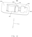
FIG. 10 is a diagrammatic view of an elastic element of the key structure ofFIG. 9 . -
FIG. 11 is a diagrammatic view of a movable element of the key structure ofFIG. 9 . -
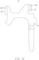
FIG. 12 is a diagrammatic view of a first terminal of the key structure ofFIG. 9 . - The following detailed description will further describe the embodiments of the present disclosure with reference to the above drawings.
- Unless otherwise defined, all technical and scientific terms used herein have the same meaning as commonly understood by persons skill in the art. The terms used herein are only for the purpose of describing specific embodiments, and not intended to limit the embodiments of the present application.
- In this application, descriptions such as "first", "second" etc. are only used for description purposes and should not be understood as indicating or implying their relative importance or implying the number of indicated technical features. Thus, a feature defined as "first" and "second" may expressly or implicitly include at least one of that features. In the description of the present application, "plurality" means more than one unless expressly and specifically defined otherwise.
- The embodiments of the present application are described here with reference to sectional views, which are schematic diagrams of idealized embodiments (and intermediate structures) of the present application. Therefore, the difference in the shape of the drawing due to the manufacturing process and/or tolerance is predictable. Accordingly, the embodiments of the present application should not be interpreted as limited to the specific shape of the area illustrated here, but should include, for example, the deviation of the shape due to manufacturing. The areas shown in the drawings are only schematic, and their shape is not used to illustrate the actual shape of the device, and is not used to limit the scope of the present disclosure.
- Some embodiments of the present application will be described in detail below with reference to the drawings. The following embodiments and features of the embodiments may be combined with each other in the absence of conflict.
- Referring to
FIGS. 1 and2 , the first embodiment provides akey structure 100, including akey cap 10, anupper cover 20, amovable element 30, anelastic element 40, apressure sensing module 50, abase 60, and acircuit board 70. Theupper cover 20 defines anopening 201 passing through theupper cover 20, and an end of themovable element 30 is connected with thekey cap 10 through theopening 201. Theelastic element 40 is sleeved on themovable element 30. Thepressure sensing module 50 is arranged on thebase 60 and electrically connected with thecircuit board 70. Thebase 60 is adapted to theupper cover 20, and theelastic element 40 and thepressure sensing module 50 are arranged in the space enclosed by theupper cover 20 and thebase 60. - Referring to
FIG. 2 ,FIG.4 , andFIG.5 , themovable element 30 includes abody portion 301 and anextension portion 302 and a pushingportion 303 arranged on opposite sides of thebody portion 301. A surface of thebody portion 301 is recessed inward to form anaccommodating cavity 304. Theextension portion 302 is roughly cylindrical, and extends out of theaccommodating cavity 304. The pushingportion 303 is protruded from a surface of thebody portion 301 away from theextension portion 302, and the pushingportion 303 and theextension portion 302 are coaxially disposed. Thebody portion 301 defines aprotruding portion 305, thebody portion 301 has two side surfaces perpendicular to the surface where theaccommodating cavity 304 is located, and theprotruding portion 305 is formed by extending the side surfaces toward a firstelastic piece 80. Themovable element 30 may be, but is not limited to, a plunger. - Referring to
FIGS. 2 and7 , thebase 60 includes amain body 61 and a first connectingportion 62 and a second connectingportion 63 arranged on opposite sides of themain body 61. The first connectingportion 62 and the second connectingportion 63 are roughly cylindrical. The first connectingportion 62 is protruded from a surface of themain body 61 and defines anaccommodating hole 621. The second connectingportion 63 is protruded from the surface of themain body 61 away from the first connectingportion 62, and the position of the second connectingportion 63 corresponds to the position of the first connectingportion 62. Theaccommodating hole 621 extends through thebody 61 to the second connectingportion 63. - One end of the
extension portion 302 away from thebody portion 301 is accommodated in theaccommodating hole 621. Theelastic element 40 is sleeved on theextension portion 302 and the first connectingportion 62, and two ends of theelastic element 40 are respectively abutted against thebody portion 301 of themovable element 30 and themain body 61 of thebase 60. Theelastic element 40 may be, but not limited to, a spring. Theextension portion 302 and the first connectingportion 62 are configured for positioning theelastic element 40. In other embodiments, theextension portion 302 and the first connectingportion 62 may be omitted, and theelastic element 40 may be elastically resisted between themovable element 30 and thebase 60. - The
circuit board 70 is sleeved on the second connectingportion 63. In other embodiments, the second connectingportion 63 may be omitted, and thecircuit board 70 may be directly fixed to the surface of thebase 60 away from theelastic element 40. - Referring to
FIG. 3 , in this embodiment, thepressure sensing module 50 includes apressure sensing element 51 and a conductingelement 52. The position of thepressure sensing element 51 corresponds to the position of themovable element 30, thus, thepressure sensing element 51 can come into contact with the movable element 30 (referring toFIGS. 2 and4 ) after being pressed. Thepressure sensing element 51 is also used to monitor the pressure experienced by the movable element 30 (referring toFIGS. 2 and4 ) and convert the pressure into a pressure signal. The conductingelement 52 conducts the pressure signal to the circuit board 70 (referring toFIG. 2 ). - Furthermore, as shown in
FIG. 3 , thepressure sensing module 50 includes afirst board 501 , asecond board 502, and athird board 503, and thesecond board 502 and thethird board 503 are disposed on the same side of thefirst board 501. Thesecond board 502 and thethird board 503 both define apressure sensing element 51, and thepressure sensing element 51 may be, but not limited to, a pressure sensor. After being pressed, the bottom of thebody portion 301 can be in contact with the twopressure sensing elements 51. Thefirst board 501 is further provided with two conductingelements 52, wherein one conductingelement 52 is arranged close to thesecond board 502, and the other conductingelement 52 is arranged close to thethird board 503. The conductingelement 52 may be, but is not limited to, solder pins. The conductingelement 52 penetrates through thebase 60 and is electrically connected to thecircuit board 70. In this embodiment, thepressure sensing module 50 is approximately axially symmetrical about the vertical bisector of thefirst board 501, and the vertical bisector is approximately parallel to the extending directions of thesecond board 502 and thethird board 503. Thefirst board 501, thesecond board 502, and thethird board 503 are formed in the shape of a half ring, and the half ring is arranged around the outer wall of the first connectingportion 62. The area of the twopressure sensing elements 51 that can sense the pressure exceeds 50% of the pressable area of thekey cap 10. Thus, users do not need to press the center of thekey cap 10, thepressure sensing element 51 can also quickly sense the pressure change, and can even use the unbalanced pressure on both sides to generate different pressure signals as extended operation commands. - Referring to
FIG. 2 , theupper cover 20 defines a snap-fit ear 202, the snap-fit ear 202 defines aclamping slot 203, thebase 60 defines a clampingprotrusion 601, and the clampingprotrusion 601 is clamped with theclamping slot 203. Accordingly, the assembly and disassembly between theupper cover 20 and the base 60 are facilitated. - Referring to
FIG. 2 ,FIG. 6 , andFIG. 7 , thekey structure 100 further includes a firstelastic piece 80 and a secondelastic piece 90 arranged on thebase 60. The firstelastic piece 80 and the secondelastic piece 90 are electrically connected to thecircuit board 70, and the secondelastic piece 90 is arranged between the firstelastic piece 80 and themovable element 30. - Furthermore, as shown in
FIG. 6 , the firstelastic piece 80 includes afixed part 801 and abent part 802 connected with thefixed part 801. Two arc-shapedprotrusions 803 are symmetrically arranged on thebent part 802, and the arc-shapedprotrusions 803 protrude toward the secondelastic piece 90. Referring toFIGS. 4 and6 , thebody portion 301 of themovable element 30 defines two protrudingportions 305 protruding toward thebent part 802 of the firstelastic piece 80. The positions of the two protrudingportions 305 correspond to the positions of the two arc-shapedprotrusions 803. Thebent part 802 of the firstelastic piece 80 and the secondelastic piece 90 are in contact when thekey structure 100 is not being pressed. - Referring to
FIG. 7 , when the user presses thekey cap 10, themovable element 30 connected to thekey cap 10 moves downward. At this time, the protrudingportion 305 contacts the arc-shapedprotrusion 803 and squeezes thebent part 802, so that thebent part 802 moves toward thefixed part 801 and separates from the secondelastic piece 90. The firstelastic piece 80 is not in contact with the secondelastic piece 90, and thecircuit board 70 outputs a corresponding signal. When the user continues to press down, the bottom of thebody portion 301 of themovable element 30 is in contact with the pressure sensing element 51 (referring toFIG. 3 ) of thepressure sensing module 50, and thepressure sensing element 51 monitors the pressure on themovable element 30 and converts the pressure into a pressure signal, the conductingelement 52 conducts the pressure signal to thecircuit board 70, and thecircuit board 70 outputs a corresponding signal. For example, after pressing thekey cap 10 for several seconds, the same command can be repeatedly executed in word processing, and the speed of the repeated command is determined by the pressing pressure; in a fighting game, press thekey cap 10 for several seconds, the strength of the attack can be determined according to the pressing force; when playing a music rhythm game, press thekey cap 10 for several seconds to simulate the playing loudness of a real musical instrument according to the pressing force. - Referring to
FIGS. 8 and9 , the second embodiment provides akey structure 200, including anupper cover 20A, amovable element 30A, anelastic element 40A, apressure sensing module 50A, abase 60A, and afirst terminal 11. Theupper cover 20A defines anopening 201A passing through theupper cover 20, and an end of themovable element 30A passes through theopening 201A and is exposed to theupper cover 20A. Thepressure sensing module 50A is arranged on thebase 60A, and thepressure sensing module 50A is electrically connected to the circuit board (not shown inFIGS. 8 and9 ). - The structure and function of the
pressure sensing module 50A in this embodiment are the same as those of the pressure sensing module 50 (referring toFIG. 3 ) in the first embodiment, which will not be repeated here. - Referring to
FIG. 10 , theelastic element 40A includes anelement body 401, and afirst slot 402 and asecond slot 403 arranged on theelement body 401. Thefirst slot 402 is provided with a thirdelastic piece 407 fixed at one end and movable at the other end, the thirdelastic piece 407 is roughly arc-shaped. Theelement body 401 includes amovable end 404 close to thefirst slot 402 and afixed end 405 close to thesecond slot 403, and themovable end 404 can move relative to thefixed end 405. Referring toFIG. 11 , themovable element 30A includes amovable block 31 and two resistingblocks 32 extending from the bottom of themovable block 31 in a direction towards theelastic element 40A. The two resistingblocks 32 and a bottom surface of themovable block 31 form agroove 33, and themovable element 30A is arranged on theelement body 401 of theelastic element 40A through thegroove 33 and the two resistingblocks 32. Referring toFIGS. 10 and11 , the arrangement direction of thefirst slot 402 and thesecond slot 403 is defined as the first direction X, and the direction perpendicular to the first direction X in the plane of theelement body 401 is the second direction Y, and the direction perpendicular to the first direction X and the second direction Y is the third direction Z. It can be understood that the third direction Z is the pressing direction. Thegroove 33 is arranged on theelement body 401 along the second direction Y. Thegroove 33 cooperates with the two resistingblocks 32 to clamp themovable element 30A on theelement body 401 between thefirst slot 402 and thesecond slot 403. - Referring to
FIG. 12 , thefirst terminal 11 includes a firstterminal body 111 and a firstprotruding part 112 and asecond protrusion 113 arranged on the firstterminal body 111. The firstterminal body 111 is roughly in a "7" shape. The firstprotruding part 112 is engaged with the third elastic piece 407 (referring toFIG. 10 ), and the secondprotruding part 113 is engaged with the second slot 403 (referring toFIG. 10 ). Furthermore, afirst notch 1121 is formed on the outer edge side wall of the first protrudingportion 112, and asecond notch 1131 is formed on the outer edge side wall of the second protrudingportion 113. Thefirst notch 1121 is engaged with the thirdelastic piece 407, and thesecond notch 1131 is engaged with thesecond slot 403. The shapes of thefirst notch 1121 and thesecond notch 1131 may be, but are not limited to, a trapezoid or a V-shape. Theelastic element 40A is fixed on thefirst terminal 11 through the engagement between thesecond notch 1131 and thesecond slot 403 and the engagement between thefirst notch 1121 and the thirdelastic piece 407. - Through the cooperation between the
first notch 1121 and the thirdelastic piece 407 and the cooperation between thesecond notch 1131 and thesecond slot 403, the stability and wear resistance of the key structure are improved, and the product life and the conductivity can also be improved. - As shown in
FIG. 9 , thekey structure 200 in this embodiment further includes asecond terminal 12 and athird terminal 13. The end of thesecond terminal 12 close to theupper cover 20A defines afirst contact 121 towards theelastic element 40A, and the end of thethird terminal 13 close to theelastic element 40A defines asecond contact 131. Themovable end 404 of theelastic element 40A defines athird contact 406 facing thesecond contact 131, and thethird contact 406 is disposed between thefirst contact 121 and thesecond contact 131. - Referring to
FIGS. 8 and9 , thebase 60A is adapted to theupper cover 20A and forms an accommodation space, theelastic element 40A, thepressure sensing module 50A, and the first protrudingpart 112 and the secondprotruding part 113 of thefirst terminal 11 are all arranged in the accommodation space. Thebase 60A defines a through hole (not shown in the drawings) passing through thebase 60A, and thesecond terminal 12, thethird terminal 13, and the firstterminal body 111 respectively pass through the through hole and protrude out. - When the key structure is not being pressed, the
elastic element 40A is in contact with thefirst contact 121 of thesecond terminal 12, which is a rest state (Off). After being pressed, themovable block 31 of themovable element 30A squeezes theelement body 401 located at thefirst slot 402 and thesecond slot 403. Under the action of the elastic force of the thirdelastic piece 407, thethird contact 406 contacts thesecond contact 131 to form a conduction circuit and output a corresponding signal. - When the user continues to press down, the two resisting
blocks 32 of themovable element 30A come into contact with thepressure sensing elements 51, thepressure sensing elements 51 monitor the pressure on themovable element 30A and converts the pressure into a pressure signal, and the conductingelements 52 conduct the pressure signal to the circuit board. The circuit board outputs a corresponding signal. For example, after pressing for several seconds, the same command can be repeatedly executed in word processing, and the speed of the repeated command is determined by the pressing pressure; in a fighting game, press for several seconds, the strength of the attack can be determined according to the pressing force; when playing a music rhythm game, press for several seconds to simulate the playing loudness of a real musical instrument according to the pressing force.. - In the key structure of the present application, a pressure sensing module electrically connected with a circuit board is set to monitor the pressure pressed by the user, and then a composite signal can be provided according to the pressure of the user's pressing to provide more commands. The key structure of the present application is sensitive, simple, and efficient in operation, which can improve the user's experience.
- The above descriptions are some specific embodiments of the present application, but the actual application process cannot be limited only to these embodiments. For those of ordinary skill in the art, other modifications and changes made according to the technical concept of the present application should all belong to the protection scope of the present application.
Claims (10)
- A key structure (100), characterized in that, comprising:a key cap (10);a movable element (30), an end of the movable element (30) connected to the key cap (10);a base (60) defining an accommodating hole (621), another end of the movable element (30) away from the key cap (10) accommodated in the accommodating hole (621);an elastic element (40) elastically resisting between the movable element (30) and the base (60);a pressure sensing module (50) arranged on the base (60), the pressure sensing module (50) comprising a pressure sensing element (51) and a conducting element (52), the pressure sensing element (51) configured to be in contact with the movable element (30) after being pressed by a pressure, monitoring the pressure on the movable element (30), and converting the pressure into a pressure signal; anda circuit board (70) electrically connected to the pressure sensing module (50), and the conducting element (52) configured to conduct the pressure signal to the circuit board (70).
- The key structure (100) of claim 1, characterized in that, the pressure sensing module (50) further comprises a first board (501), a second board (502), and a third board (503), and the second board (503) and the third board (503) are arranged on a same side of the first board (501); the pressure sensing element (51) is arranged on both the second board (502) and the third board (503); two conducting elements (52) are provided on the first board (501), one of the two conducting elements (52) is arranged close to the second board (502), and another of the two conducting elements (52) is arranged close to the third board (503).
- The key structure (100) of claim 1, characterized in that, the movable element (30) comprises a body portion (301), an extension portion (302), and a pushing portion (303), the extension portion (302) and the pushing portion (303) are arranged on opposite sides of the body portion (301); the pushing portion (303) is connected to the key cap (10), the extension portion (302) is partially accommodated in the accommodating hole (621), and the elastic element (40) is sleeved on the extension portion (302); when the movable element (30) is pressed, the body portion (301) is in contact with the pressure sensing element (51).
- The key structure (100) of claim 1, characterized in that, further comprising a first elastic piece (80) and a second elastic piece (90) arranged on the base (60), wherein the first elastic piece (80) and the second elastic piece (90) are electrically connected to the circuit board (70), and the second elastic piece (90) is arranged between the first elastic piece (80) and the movable element (30).
- The key structure (100) of claim 4, characterized in that, the first elastic piece (80) comprises a fixed part (801) and a bent part (802) connected to the fixed part (801), the movable element (30) comprises a body portion (301) defining a protruding portion (305), and the bent part (802) is configured to be in contact with the protruding portion (305) and move toward the fixed part (801) when the movable element (30) is pressed.
- The key structure (100) of claim 1, characterized in that, further comprising an upper cover (20) comprising an opening (201) and a snap-fit ear (202), wherein an end of the movable element (30) passes through the opening (201) and connects to the key cap (10); the snap-fit ear (202) defines a clamping slot (203), the base (60) defines a clamping protrusion (601), and the clamping protrusion (601) is engaged with the clamping slot (203).
- A key structure (200), characterized in that, comprising:an upper cover (20A) defining an opening (201A), the opening (201A) passing through the upper cover (20A);a base (60A), the base (60A) and the upper cover (20A) cooperatively forming an accommodation space;an elastic element (40A) accommodated in the accommodation space, the elastic element (40A) comprising an element body (401), and a first slot (402) and a second slot (403) arranged on the element body (401), and a third elastic piece (407) arranged in the first slot (402);a first terminal (11) comprising a first terminal body (111), and a first protruding part (112) and a second protruding part (113) arranged on the first terminal body (111), the first protruding part (112) engaged with the third elastic piece (407), the second protruding part (113) engaged with the second slot (403);a movable element (30A) comprising a movable block (31) and two resisting blocks (32) extending from the movable block (31), wherein the two resisting blocks (32) and a bottom surface of the movable block (31) cooperatively form a groove (33), the groove (33) is engaged with the element body (401) located at the first slot (402) and the second slot (403), the movable block (31) is configured to press against the elastic element (40A) to drive the elastic element (40A) to move when the movable element (30A) is pressed;a pressure sensing module (50A) arranged on the base (60A), the pressure sensing module (50A) comprising a pressure sensing element (51) and a conducting element (52), the pressure sensing element (51) configured to be in contact with the resisting block (32) of the movable element (30A) after being pressed by a pressure, monitoring the pressure on the movable element (30A), and converting the pressure into a pressure signal; anda circuit board (70) electrically connected to the pressure sensing module (50A), and the conducting element (52) is configured for conducting the pressure signal to the circuit board (70).
- The key structure (200) of claim 7, characterized in that, the pressure sensing module (50A) further comprises a first board (501), a second board (502), and a third board (503), and the second board (502) and the third board (503) are arranged on a same side of the first board (501); the pressure sensing element (51) is arranged on both the second board (502) and the third board (503); the first board (501) is provided with two conducting elements (52), one of the two conducting elements (52) is arranged close to the second board (502), and another of the two conducting elements is arranged close to the third board (503).
- The key structure (200) of claim 7, characterized in that, further comprising a second terminal (12) and a third terminal (13); wherein the second terminal (12) defines a first contact (121), and the third terminal (13) defines a second contact (131); the element body (401) comprises a movable end (404) close to the first slot (402) and a fixed end (405) close to the second slot (403); the fixed end (405) is engaged with the second protruding part (113); the movable end (404) defines a third contact (406), the third contact (406) is arranged between the first contact (121) and the second contact (131), and is configured to be in contact with the first contact (121) or the second contact (131).
- The key structure (200) of claim 7, characterized in that, the elastic element (40A), the pressure sensing module (50A), the first protruding part (112), and the second protruding part (113) are all arranged in the accommodation space; the base (60A) defines a through hole, and each of the second terminal (12), the third terminal (13), and the first terminal body (111) passes through the through hole and protrudes from the base (60A).
Applications Claiming Priority (1)
| Application Number | Priority Date | Filing Date | Title |
|---|---|---|---|
| CN202111481332.2A CN116230437A (en) | 2021-12-06 | 2021-12-06 | key structure |
Publications (1)
| Publication Number | Publication Date |
|---|---|
| EP4191631A1 true EP4191631A1 (en) | 2023-06-07 |
Family
ID=81326249
Family Applications (1)
| Application Number | Title | Priority Date | Filing Date |
|---|---|---|---|
| EP22166093.9A Withdrawn EP4191631A1 (en) | 2021-12-06 | 2022-03-31 | Key structure |
Country Status (3)
| Country | Link |
|---|---|
| US (1) | US11869729B2 (en) |
| EP (1) | EP4191631A1 (en) |
| CN (1) | CN116230437A (en) |
Families Citing this family (2)
| Publication number | Priority date | Publication date | Assignee | Title |
|---|---|---|---|---|
| US12315685B2 (en) | 2021-05-26 | 2025-05-27 | Hewlett-Packard Development Company, L.P. | Specialized keyboard keycaps |
| WO2022250691A1 (en) * | 2021-05-26 | 2022-12-01 | Kingston Technology Corporation | Specialized key switches for electronic key caps |
Citations (2)
| Publication number | Priority date | Publication date | Assignee | Title |
|---|---|---|---|---|
| US20170330704A1 (en) * | 2016-05-13 | 2017-11-16 | Primax Electronics Ltd. | Key strcture |
| US20180019080A1 (en) * | 2016-07-15 | 2018-01-18 | Primax Electronics Ltd. | Keyboard |
Family Cites Families (2)
| Publication number | Priority date | Publication date | Assignee | Title |
|---|---|---|---|---|
| TWI655658B (en) * | 2017-11-29 | 2019-04-01 | 達方電子股份有限公司 | Keyswitch with adjustable tactile feedback and related adjusting method |
| TWM561318U (en) | 2018-01-19 | 2018-06-01 | 大陸商東莞市凱華電子有限公司 | Keyboard switch |
-
2021
- 2021-12-06 CN CN202111481332.2A patent/CN116230437A/en active Pending
-
2022
- 2022-03-31 EP EP22166093.9A patent/EP4191631A1/en not_active Withdrawn
- 2022-04-08 US US17/716,242 patent/US11869729B2/en active Active
Patent Citations (2)
| Publication number | Priority date | Publication date | Assignee | Title |
|---|---|---|---|---|
| US20170330704A1 (en) * | 2016-05-13 | 2017-11-16 | Primax Electronics Ltd. | Key strcture |
| US20180019080A1 (en) * | 2016-07-15 | 2018-01-18 | Primax Electronics Ltd. | Keyboard |
Also Published As
| Publication number | Publication date |
|---|---|
| CN116230437A (en) | 2023-06-06 |
| US11869729B2 (en) | 2024-01-09 |
| US20230178312A1 (en) | 2023-06-08 |
Similar Documents
| Publication | Publication Date | Title |
|---|---|---|
| US11869729B2 (en) | Key structure | |
| US3993884A (en) | Detachably mounted keyboard pushbutton actuators and housing assembly | |
| TW201301321A (en) | Push button and electronic device using the push button | |
| TWI616916B (en) | Push-button switch and movable contact member | |
| GB2046996A (en) | Electrical switch | |
| US7745744B2 (en) | Multidirectional switch | |
| JPS5858771B2 (en) | Multi-contact push button switch | |
| TWI788130B (en) | Push-button structure | |
| US9257244B2 (en) | Electronic device with power switch | |
| US8143544B2 (en) | Switch | |
| CN217643653U (en) | Earphone with press control | |
| CN209765447U (en) | thin film contact type optical keyboard | |
| CN209981071U (en) | Ultrathin optical keyboard of notebook computer | |
| JP2001176588A (en) | Connector for flat cable | |
| US10032574B2 (en) | Membrane keyswitch with a spacer isolated trigger zone | |
| CN105304382A (en) | Key device | |
| CN222927340U (en) | Force sensor switch assembly for preventing stress interference of PCB (printed circuit board) | |
| CN220189478U (en) | Tact switch | |
| JP2021190316A (en) | Input device | |
| JPH0338740Y2 (en) | ||
| JP3177154U (en) | Push switch | |
| CN109786157B (en) | Switching device | |
| JP2024099085A (en) | Dome type contact member and pressing switch member including the same | |
| KR102176089B1 (en) | Signal input device and smart device comprising the same | |
| JP2689497B2 (en) | Switch device manufacturing method |
Legal Events
| Date | Code | Title | Description |
|---|---|---|---|
| PUAI | Public reference made under article 153(3) epc to a published international application that has entered the european phase |
Free format text: ORIGINAL CODE: 0009012 |
|
| STAA | Information on the status of an ep patent application or granted ep patent |
Free format text: STATUS: REQUEST FOR EXAMINATION WAS MADE |
|
| 17P | Request for examination filed |
Effective date: 20230321 |
|
| AK | Designated contracting states |
Kind code of ref document: A1 Designated state(s): AL AT BE BG CH CY CZ DE DK EE ES FI FR GB GR HR HU IE IS IT LI LT LU LV MC MK MT NL NO PL PT RO RS SE SI SK SM TR |
|
| STAA | Information on the status of an ep patent application or granted ep patent |
Free format text: STATUS: THE APPLICATION IS DEEMED TO BE WITHDRAWN |
|
| 18D | Application deemed to be withdrawn |
Effective date: 20241001 |