EP4191558A1 - Data processing method and apparatus, device, and storage medium - Google Patents
Data processing method and apparatus, device, and storage medium Download PDFInfo
- Publication number
- EP4191558A1 EP4191558A1 EP21868457.9A EP21868457A EP4191558A1 EP 4191558 A1 EP4191558 A1 EP 4191558A1 EP 21868457 A EP21868457 A EP 21868457A EP 4191558 A1 EP4191558 A1 EP 4191558A1
- Authority
- EP
- European Patent Office
- Prior art keywords
- target
- vehicle
- lane
- target vehicle
- distance
- Prior art date
- Legal status (The legal status is an assumption and is not a legal conclusion. Google has not performed a legal analysis and makes no representation as to the accuracy of the status listed.)
- Pending
Links
Images





Classifications
-
- G—PHYSICS
- G08—SIGNALLING
- G08G—TRAFFIC CONTROL SYSTEMS
- G08G1/00—Traffic control systems for road vehicles
- G08G1/16—Anti-collision systems
- G08G1/167—Driving aids for lane monitoring, lane changing, e.g. blind spot detection
-
- B—PERFORMING OPERATIONS; TRANSPORTING
- B60—VEHICLES IN GENERAL
- B60W—CONJOINT CONTROL OF VEHICLE SUB-UNITS OF DIFFERENT TYPE OR DIFFERENT FUNCTION; CONTROL SYSTEMS SPECIALLY ADAPTED FOR HYBRID VEHICLES; ROAD VEHICLE DRIVE CONTROL SYSTEMS FOR PURPOSES NOT RELATED TO THE CONTROL OF A PARTICULAR SUB-UNIT
- B60W30/00—Purposes of road vehicle drive control systems not related to the control of a particular sub-unit, e.g. of systems using conjoint control of vehicle sub-units
- B60W30/18—Propelling the vehicle
- B60W30/18009—Propelling the vehicle related to particular drive situations
- B60W30/18163—Lane change; Overtaking manoeuvres
-
- B—PERFORMING OPERATIONS; TRANSPORTING
- B60—VEHICLES IN GENERAL
- B60W—CONJOINT CONTROL OF VEHICLE SUB-UNITS OF DIFFERENT TYPE OR DIFFERENT FUNCTION; CONTROL SYSTEMS SPECIALLY ADAPTED FOR HYBRID VEHICLES; ROAD VEHICLE DRIVE CONTROL SYSTEMS FOR PURPOSES NOT RELATED TO THE CONTROL OF A PARTICULAR SUB-UNIT
- B60W50/00—Details of control systems for road vehicle drive control not related to the control of a particular sub-unit, e.g. process diagnostic or vehicle driver interfaces
- B60W50/0097—Predicting future conditions
-
- B—PERFORMING OPERATIONS; TRANSPORTING
- B60—VEHICLES IN GENERAL
- B60W—CONJOINT CONTROL OF VEHICLE SUB-UNITS OF DIFFERENT TYPE OR DIFFERENT FUNCTION; CONTROL SYSTEMS SPECIALLY ADAPTED FOR HYBRID VEHICLES; ROAD VEHICLE DRIVE CONTROL SYSTEMS FOR PURPOSES NOT RELATED TO THE CONTROL OF A PARTICULAR SUB-UNIT
- B60W60/00—Drive control systems specially adapted for autonomous road vehicles
- B60W60/001—Planning or execution of driving tasks
-
- G—PHYSICS
- G08—SIGNALLING
- G08G—TRAFFIC CONTROL SYSTEMS
- G08G1/00—Traffic control systems for road vehicles
- G08G1/01—Detecting movement of traffic to be counted or controlled
- G08G1/052—Detecting movement of traffic to be counted or controlled with provision for determining speed or overspeed
-
- G—PHYSICS
- G08—SIGNALLING
- G08G—TRAFFIC CONTROL SYSTEMS
- G08G1/00—Traffic control systems for road vehicles
- G08G1/09—Arrangements for giving variable traffic instructions
- G08G1/0962—Arrangements for giving variable traffic instructions having an indicator mounted inside the vehicle, e.g. giving voice messages
- G08G1/0967—Systems involving transmission of highway information, e.g. weather, speed limits
- G08G1/096708—Systems involving transmission of highway information, e.g. weather, speed limits where the received information might be used to generate an automatic action on the vehicle control
-
- G—PHYSICS
- G08—SIGNALLING
- G08G—TRAFFIC CONTROL SYSTEMS
- G08G1/00—Traffic control systems for road vehicles
- G08G1/09—Arrangements for giving variable traffic instructions
- G08G1/0962—Arrangements for giving variable traffic instructions having an indicator mounted inside the vehicle, e.g. giving voice messages
- G08G1/0967—Systems involving transmission of highway information, e.g. weather, speed limits
- G08G1/096708—Systems involving transmission of highway information, e.g. weather, speed limits where the received information might be used to generate an automatic action on the vehicle control
- G08G1/096725—Systems involving transmission of highway information, e.g. weather, speed limits where the received information might be used to generate an automatic action on the vehicle control where the received information generates an automatic action on the vehicle control
-
- G—PHYSICS
- G08—SIGNALLING
- G08G—TRAFFIC CONTROL SYSTEMS
- G08G1/00—Traffic control systems for road vehicles
- G08G1/09—Arrangements for giving variable traffic instructions
- G08G1/0962—Arrangements for giving variable traffic instructions having an indicator mounted inside the vehicle, e.g. giving voice messages
- G08G1/0967—Systems involving transmission of highway information, e.g. weather, speed limits
- G08G1/096766—Systems involving transmission of highway information, e.g. weather, speed limits where the system is characterised by the origin of the information transmission
- G08G1/096775—Systems involving transmission of highway information, e.g. weather, speed limits where the system is characterised by the origin of the information transmission where the origin of the information is a central station
-
- G—PHYSICS
- G08—SIGNALLING
- G08G—TRAFFIC CONTROL SYSTEMS
- G08G1/00—Traffic control systems for road vehicles
- G08G1/09—Arrangements for giving variable traffic instructions
- G08G1/0962—Arrangements for giving variable traffic instructions having an indicator mounted inside the vehicle, e.g. giving voice messages
- G08G1/0967—Systems involving transmission of highway information, e.g. weather, speed limits
- G08G1/096766—Systems involving transmission of highway information, e.g. weather, speed limits where the system is characterised by the origin of the information transmission
- G08G1/096791—Systems involving transmission of highway information, e.g. weather, speed limits where the system is characterised by the origin of the information transmission where the origin of the information is another vehicle
-
- B—PERFORMING OPERATIONS; TRANSPORTING
- B60—VEHICLES IN GENERAL
- B60W—CONJOINT CONTROL OF VEHICLE SUB-UNITS OF DIFFERENT TYPE OR DIFFERENT FUNCTION; CONTROL SYSTEMS SPECIALLY ADAPTED FOR HYBRID VEHICLES; ROAD VEHICLE DRIVE CONTROL SYSTEMS FOR PURPOSES NOT RELATED TO THE CONTROL OF A PARTICULAR SUB-UNIT
- B60W2520/00—Input parameters relating to overall vehicle dynamics
- B60W2520/10—Longitudinal speed
-
- B—PERFORMING OPERATIONS; TRANSPORTING
- B60—VEHICLES IN GENERAL
- B60W—CONJOINT CONTROL OF VEHICLE SUB-UNITS OF DIFFERENT TYPE OR DIFFERENT FUNCTION; CONTROL SYSTEMS SPECIALLY ADAPTED FOR HYBRID VEHICLES; ROAD VEHICLE DRIVE CONTROL SYSTEMS FOR PURPOSES NOT RELATED TO THE CONTROL OF A PARTICULAR SUB-UNIT
- B60W2552/00—Input parameters relating to infrastructure
- B60W2552/10—Number of lanes
-
- B—PERFORMING OPERATIONS; TRANSPORTING
- B60—VEHICLES IN GENERAL
- B60W—CONJOINT CONTROL OF VEHICLE SUB-UNITS OF DIFFERENT TYPE OR DIFFERENT FUNCTION; CONTROL SYSTEMS SPECIALLY ADAPTED FOR HYBRID VEHICLES; ROAD VEHICLE DRIVE CONTROL SYSTEMS FOR PURPOSES NOT RELATED TO THE CONTROL OF A PARTICULAR SUB-UNIT
- B60W2554/00—Input parameters relating to objects
- B60W2554/40—Dynamic objects, e.g. animals, windblown objects
- B60W2554/404—Characteristics
- B60W2554/4041—Position
-
- B—PERFORMING OPERATIONS; TRANSPORTING
- B60—VEHICLES IN GENERAL
- B60W—CONJOINT CONTROL OF VEHICLE SUB-UNITS OF DIFFERENT TYPE OR DIFFERENT FUNCTION; CONTROL SYSTEMS SPECIALLY ADAPTED FOR HYBRID VEHICLES; ROAD VEHICLE DRIVE CONTROL SYSTEMS FOR PURPOSES NOT RELATED TO THE CONTROL OF A PARTICULAR SUB-UNIT
- B60W2554/00—Input parameters relating to objects
- B60W2554/80—Spatial relation or speed relative to objects
- B60W2554/802—Longitudinal distance
-
- B—PERFORMING OPERATIONS; TRANSPORTING
- B60—VEHICLES IN GENERAL
- B60W—CONJOINT CONTROL OF VEHICLE SUB-UNITS OF DIFFERENT TYPE OR DIFFERENT FUNCTION; CONTROL SYSTEMS SPECIALLY ADAPTED FOR HYBRID VEHICLES; ROAD VEHICLE DRIVE CONTROL SYSTEMS FOR PURPOSES NOT RELATED TO THE CONTROL OF A PARTICULAR SUB-UNIT
- B60W2720/00—Output or target parameters relating to overall vehicle dynamics
- B60W2720/10—Longitudinal speed
- B60W2720/106—Longitudinal acceleration
-
- H—ELECTRICITY
- H04—ELECTRIC COMMUNICATION TECHNIQUE
- H04W—WIRELESS COMMUNICATION NETWORKS
- H04W4/00—Services specially adapted for wireless communication networks; Facilities therefor
- H04W4/30—Services specially adapted for particular environments, situations or purposes
- H04W4/40—Services specially adapted for particular environments, situations or purposes for vehicles, e.g. vehicle-to-pedestrians [V2P]
- H04W4/46—Services specially adapted for particular environments, situations or purposes for vehicles, e.g. vehicle-to-pedestrians [V2P] for vehicle-to-vehicle communication [V2V]
Definitions
- This application relates to the technical field of intelligent driving, and in particular, to a data processing method and apparatus, a device, and a medium.
- a driverless vehicle is an intelligent vehicle that senses a road environment through an in-vehicle sensor system, automatically plans a driving route, and controls the vehicle to reach a predetermined destination.
- the driverless vehicle may achieve a purpose of autonomous driving by relying on a computer-system-based intelligent pilot in the vehicle.
- the driverless vehicle when changing lanes, the driverless vehicle generally requires surrounding vehicles to cooperate and give way in order to obtain enough lane change space and realize safe lane change of the driverless vehicle.
- the surrounding vehicles cannot cooperate with and give way to the driverless vehicle.
- the driverless vehicle cannot find a suitable lane change opportunity, which leads to failure in the lane change of the driverless vehicle.
- An embodiment of this application provides a data processing method, performed by a computer device, the method including:
- An embodiment of this application provides a data processing apparatus, including:
- An aspect of the embodiments of this application provides a computer device, including a memory and a processor, the memory storing a computer program, the computer program, when executed by the processor, causing the processor to perform the steps of the method in one aspect of the embodiments of this application.
- An aspect of the embodiments of this application provides a computer-readable storage medium, storing a computer program, the computer program including program instructions, the program instructions, when executed by a processor, implementing the steps of the method in one aspect of the embodiments of this application.
- a computer program product or a computer program including computer instructions, the computer instructions being stored in a computer-readable storage medium.
- a processor of a computer device reads the computer instructions from the computer-readable storage medium, and the processor executes the computer instructions, so that the computer device performs the method in the various implementations of one aspect described above.
- a driverless vehicle is an intelligent vehicle that senses a road environment through an in-vehicle sensor system, automatically plans a driving route, and controls the vehicle to reach a predetermined destination.
- the driverless vehicle may use an in-vehicle sensor to sense environments around the vehicle, and control the vehicle's steering and speed according to sensed roads, vehicle positions, and obstacle information, so that the vehicle can safely and reliably travel on the roads.
- the driverless vehicle integrates many technologies such as automatic control, system architecture, artificial intelligence, and vision computing, and is a highly developed product of computer science, pattern recognition, and intelligent control technologies.
- embodiments of this application provide a vehicle lane change method and apparatus, a device, and a medium, which can improve a lane change success rate of a vehicle.
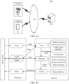
- FIG. 1a is a system architecture 100 to which a vehicle lane change method according to an embodiment of this application applies.
- a system architecture 100 may include one or more of terminal devices 101 and 102, a network 104, and a server 105.
- the network 104 is configured to provide a medium of a communication link between the server 105 and the terminal devices 101 and 102.
- the network 104 may include various connection types, such as a wired or wireless communication link, or a fiber optic cable.
- the terminal devices 101 and 102 may be a variety of computing devices having displays and mounted or configured on conventional vehicles, including, but not limited to, computers, smart phones, tablet computers, and the like. There may be any quantities of terminal devices, networks, and servers according to an implementation requirement.
- the server 105 may be a server cluster including a plurality of servers.
- the vehicle lane change method according to this embodiment of this application is generally performed by the terminal devices 101 and 102. However, it is easy for a person skilled in the art to understand that the vehicle lane change method according to this embodiment of this application may also be performed by the server 105, which is not specially limited in this exemplary embodiment.
- FIG. 1b is a schematic structural diagram of an intelligent driving system according to an embodiment of this application.
- the intelligent driving system is generally mounted on a conventional vehicle to build the whole system.
- the intelligent driving system may include a hardware part and a software part.
- the hardware part may include a sensor, a signal communication module, a brake, and the like.
- the software part may include a sensing module, a planning module, a control module, and the like, which may be mounted in the terminal device 101 or the terminal device 102 shown in FIG. 1a .
- the sensor may be configured to acquire a lot of information about surroundings, such as positions, speeds, and possible behaviors of obstacles (the obstacles herein may refer to other vehicles, pedestrians, cones, guardrails, etc. around the driverless vehicle), travelable regions, and traffic rules.
- the sensor may include, but is not limited to, a camera, a lidar, and a millimeter wave radar.
- the camera may be configured to acquire image information, and may identify pedestrians, cars, trees, traffic lights, signal boards, and so on from the image information through the sensing module of the software part. That is, obstacles and traffic signals may be detected according to the image information.
- the lidar may be configured to acquire laser scanning reflection data, and may identify obstacles such as pedestrians, cars, and trees from the laser scanning reflection data through the sensing module.
- the millimeter wave radar may be configured to acquire reflection data, may identify obstacles and measure distances according to the reflection data, and may achieve a purpose of assisting obstacle avoidance.
- the intelligent driving system may sense surroundings of the driverless vehicle in real time according to data acquired by the sensor.
- the planning module may make some purposeful decisions for the driverless vehicle.
- the goal generally refers to getting from an origin to a destination and avoiding obstacles, and constantly optimizing driving trajectories and behaviors to ensure safety and comfort of passengers.
- Planning may include task planning, behavior planning, and motion planning.
- Path planning may also be referred to as routing.
- a role of the task planning may be simply understood as navigation inside the intelligent driving system, that is, to guide, on a macro level, the driverless vehicle to travel from a starting point to a destination point according to a road.
- the behavior planning is also referred to as decision making.
- the behavior planning may be responsible for determining next decision to be executed by the driverless vehicle according to a goal of the path planning and a current local situation (e.g., positions and behaviors of other vehicles and pedestrians, current traffic rules, etc.).
- the behavior planning may be understood as a co-driver of the vehicle, which directs, according to a goal and a current traffic situation, a driver whether to follow or overtake, stop and wait for pedestrians to pass or bypass pedestrians, and the like.
- the motion planning may include path planning and speed planning.
- a role of the motion planning may be understood as specifically solving the problem of how the driverless vehicle travels from a point A to a point B in a small spatio-temporal region. For example, an intermediate waypoint from the point A to the point B within a short time t may be planned, including selecting specific waypoints, and a speed, an orientation, and an acceleration of the driverless vehicle when the driverless vehicle reaches each waypoint.
- the control module is the lowest level of the intelligent driving system and may be configured to implement the above planned behaviors (e.g., obstacle avoidance, lane change, etc.).
- the control module may transmit an execution instruction to the brake of the hardware part to control execution of power (throttle and gear), chassis (steering and braking) and electronic and electrical systems of the driverless vehicle, so as to realize the control over a speed and a direction of the driverless vehicle.
- the signal communication module may include vehicle-to-vehicle (V2V) communication.
- V2V communication refers to wireless-based data transmission between motor vehicles. To prevent accidents, the V2V communication transmits vehicle positions and speed information to other vehicles via a dedicated network.
- the signal communication module may exchange data with the sensing module. Vehicle positions and speed information of the other vehicles may be sensed in real time through the sensing module. In addition, vehicle positions and speed information of the current driverless vehicle may also be transmitted to the other vehicles through the signal communication module.
- the sensing module of the driverless vehicle may take autonomous measures, such as braking and deceleration, based on the information received.
- This application relates to the behavior planning in the intelligent driving system, and mainly to the issue of speed planning in lane change in driverless congestion scenarios.
- FIG. 2a and FIG. 2b are schematic diagrams of lane change scenarios of a driverless vehicle according to an embodiment of this application.
- a vehicle 10a shown in FIG. 2a is the driverless vehicle.
- the vehicle 10a When the vehicle 10a is located at an entrance to the highway or main road, the vehicle 10a has to change lanes to join the highway or main road.
- a vehicle 10b shown in FIG. 2a refers to a leader traveling in the same lane as the vehicle 10a and in front of the vehicle 10a (the vehicle 10b and the vehicle 10a are adjacent vehicles in a current lane).
- a vehicle 10c, a vehicle 10d, and a vehicle 10e are vehicles traveling in a target lane respectively.
- the vehicle 10c, the vehicle 10d, and the vehicle 10e are obstacles.
- a travelable region of the vehicle 10a in the current lane is a region L1. That is, the vehicle 10a needs to change to the target lane before traveling to an endpoint of the region L1 to prevent collision.
- the vehicle 10a may choose, according to a length of the region L1 in the current lane, a driving speed of the vehicle 10a, a driving speed of the vehicle 10b, and speeds and positions of moving vehicles in the target lane (e.g., positions and speeds of the vehicle 10c, the vehicle 10d, and the vehicle 10e in the target lane), a proper lane change gap from the target lane, that is, choose to jam between which two vehicles in the target lane.
- a proper lane change gap from the target lane
- the target lane has 4 gaps for the vehicle 10a to select.
- the 4 gaps are a front region of the vehicle 10c, a region L2 between the vehicle 10c and the vehicle 10d, a region L3 between the vehicle 10d and the vehicle 10e, and a rear region L4 of the vehicle 10e respectively.
- the vehicle 10a further needs to perform speed planning according to information such as a spacing distance between the vehicle 10c and the vehicle 10d, a safe distance between vehicles, and driving speeds respectively corresponding to the vehicle 10c and the vehicle 10d.
- a safe lane change from the current lane to the target lane is realized by changing the speed of the vehicle 10a.
- a vehicle 20a shown in FIG. 2b is the driverless vehicle that is about to change lanes to exit the highway or main road. That is, the vehicle 20a needs to change from the current lane to the target lane to achieve a purpose of exiting the highway or main road.
- the vehicle 20b refers to a leader traveling in the same lane as the vehicle 20a and in front of the vehicle 20a (the vehicle 20b and the vehicle 20a are adjacent vehicles in a current lane).
- a vehicle 20c and a vehicle 20d are vehicles traveling in the target lane respectively.
- the vehicle 20c and the vehicle 20d are obstacles.
- the vehicle 20a first needs to choose a proper lane change gap from the target lane, that is, choose to jam between which two vehicles in the target lane.
- the vehicle 20a may choose the proper lane change gap from the target lane according to information such as a driving speed of the vehicle 20a, a driving speed of the vehicle 20b, a driving speed of the vehicle 20c, and a driving speed of the vehicle 20d.
- the target lane has 3 gaps for the vehicle 20a to select.
- the 3 gaps are a front region L6 of the vehicle 20c (in practical applications, the vehicle 20c herein has completely exited the highway or main road and is already traveling in the target lane, so the region L6 herein can be ignored), a region L5 between the vehicle 20c and the vehicle 20d, and a rear region L7 of the vehicle 20d respectively.
- the vehicle 20a further needs to perform speed planning according to information such as a spacing distance between the vehicle 20c and the vehicle 20d, a safe distance between vehicles, and driving speeds respectively corresponding to the vehicle 20c and the vehicle 20d.
- a safe lane change from the current lane to the target lane is realized by changing the speed of the vehicle 20a.
- a specific process of performing speed planning on the vehicle 10a and the vehicle 20a may be obtained with reference to embodiments corresponding to FIG. 3 to FIG. 6 below.
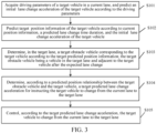
- FIG. 3 is a schematic flowchart of a data processing method according to an embodiment of this application.
- the method is performed by a computer device.
- the computer device may be a terminal device shown in FIG. 1a or a server 105 in FIG. 1a .
- the data processing method may include the following steps.
- Step S101 Acquire driving parameters of a target vehicle in a current lane, and predict an initial lane change acceleration of the target vehicle according to the driving parameters.
- the intelligent driving system may perform coarse speed planning according to driving parameters (also referred to as environmental conditions of the target vehicle) of the target vehicle (i.e., a driverless vehicle needing to change lanes, such as the vehicle 10a in the embodiment corresponding to FIG. 2a , which may be referred to as an Ego car) to predict the initial lane change acceleration corresponding to the target vehicle.
- the driving parameters may include a maximum target lane speed v m , a leading car (also referred to as a leader), and a road passing distance L m (m).
- the maximum target lane speed v m refers to a maximum speed specified in the target lane.
- the target lane refers to a lane to which the target vehicle is expected to change.
- the maximum target lane speed v m may be 120 m/s which is the maximum speed specified in the expressway.
- the leading car refers to a vehicle guiding a driving route for the target vehicle in the current lane, that is, an environmental vehicle in the current lane and traveling in front of and closest to the target vehicle.
- the road passing distance L m refers to a length of a passable road in the current lane for the target vehicle, for example, a length of the region L1 in the embodiment corresponding to FIG. 2a .
- the intelligent driving system may acquire a current driving speed v 1 of the target vehicle, and determine a first limited acceleration a 1 corresponding to the target vehicle according to the driving speed v 1 and the maximum target lane speed v m .
- the equation (1) is a piecewise function representation of the first limited acceleration a 1 , and a consideration factor in the equation (1) is a current traffic flow speed of the target lane.
- the first limited acceleration a 1 may be designed to be the maximum acceleration a max (m/s 2 ).
- the driving speed v 1 of the target vehicle is less than a difference between the maximum target lane speed v m and 0.5 and greater than or equal to the difference between the maximum target lane speed v m and 2.0
- the first limited acceleration a 1 may be designed to be 0.5 m/s 2 .
- the first limited acceleration a 1 may be designed to be 0. That is, the driving speed v 1 is continued for uniform motion.
- the driving speed v 1 of the target vehicle is greater than or equal to the sum of the maximum target lane speed v m and 0.5
- the first limited acceleration a 1 may be designed to be -(v 1 - v m )/3.0.
- all the driving speeds referred to may be instantaneous speeds in units of m/s
- all the accelerations referred to are in units of m/s 2
- all the distances referred to are in units of m. Details are not described in the subsequent description.
- the intelligent driving system further needs to consider the influence of the road passing distance L m .
- the target vehicle remains traveling in the current lane when the target vehicle searches for the right time to change lanes.
- the intelligent driving system needs to control the target vehicle to slow down. Therefore, the intelligent driving system may generate a braking acceleration a r corresponding to the target vehicle according to the driving speed v 1 and the road passing distance L m , and determine a second limited acceleration a 2 corresponding to the target vehicle according to the braking acceleration a r .
- the braking acceleration a r may refer to an acceleration used by the target vehicle to slow down.
- the intelligent driving system may acquire a road endpoint speed v min of the target vehicle in the current lane, and acquire a square difference between the driving speed v 1 and the road endpoint speed v min .
- the road endpoint speed v min is a minimum speed at which the target vehicle travels to the endpoint of the current lane.
- the road endpoint speed may be a minimum speed at which the target vehicle travels to the endpoint of the current lane when the target vehicle is located at an entrance to a highway or main road and needs to join the main road.
- the road endpoint speed may be a minimum speed at which the target vehicle exits the highway or main road or the target vehicle travels to an exit from a current road (for example, the road endpoint speed v min may be 3.0 m/s, or the road endpoint speed v min may be 0, or the road endpoint speed v min may be a preset constant parameter).
- the braking acceleration a r corresponding to the target vehicle may be determined according to a ratio of the square difference to the road passing distance L m .
- the braking acceleration a r may be calculated according to the equation (2).
- the equation (3) is a piecewise function representation of the second limited acceleration a 2 .
- the second limited acceleration a 2 may be designed to be -1.0 m/s 2 .
- the second limited acceleration a 2 may be designed to be -0.5 m/s 2 .
- the second limited acceleration a 2 may be designed to be 0. That is, the driving speed v 1 is continued for uniform motion.
- the second limited acceleration a 2 may be designed to be a max .
- the intelligent driving system further needs to consider the influence of the leading car in the current lane.
- the target vehicle may have to take more radical measures (such as shortening a following distance with the leading car) to accelerate the lane change in order to realize the lane change.
- the intelligent driving system may acquire a driving speed v 2 of the leading car, determine a first safe braking distance L b1 corresponding to the target vehicle according to the driving speed v 2 , and then determine a third limited acceleration a 3 corresponding to the target vehicle according to the first safe braking distance L b1 , the driving speed v 1 , a target following speed v f , and an estimated following duration t f .
- the first safe braking distance L b1 may be used for representing a distance that can be traveled by the target vehicle in the current lane while keeping a safe following distance from the leading car.
- the first safe braking distance L b1 may be calculated from the equation (4).
- Step S102 Predict target position information of the target vehicle according to current position information, a predicted lane change time duration, and the initial predicted lane change acceleration of the target vehicle.
- the intelligent driving system may estimate a relative position relationship between the target vehicle and a surrounding obstacle vehicle after a future period of time (e.g., 3-5s) according to the initial predicted lane change acceleration, and may select an appropriate lane change gap for lane change preparations according to the relative position relationship.
- 3-5s may be expressed as the predicted lane change time duration, that is, a duration taken by the target vehicle to change from the current lane to the target lane.
- the intelligent driving system may acquire current position information of the target vehicle, and determine target predicted position information of the target vehicle after the predicted lane change time duration according to the current position information, the predicted lane change time duration, and the initial predicted lane change acceleration a 0 ′ .
- the position information (including the current position information and the target predicted position information, and predicted position information of an obstacle vehicle mentioned later) referred to in this embodiment of this application may refer to coordinate information expressed by a Cartesian coordinate system or coordinate information expressed by a Frenet coordinate system.
- the Frenet coordinate system is a way of representing positions of a road more intuitively than conventional x, y Cartesian coordinate systems.
- positions of the vehicle on the road may be described using variables s and d, the s coordinate represents a distance along the road (also referred to as a longitudinal position), and the d coordinate represents a left-right position on the road (also referred to as a transverse position).
- the Frenet coordinate system is taken as an example to describe position information of the target vehicle and the obstacle vehicle.
- the position information in this embodiment of this application may refer to longitudinal position information in the Frenet coordinate system, i.e., the distance along the road.
- Step S103 Determine, in the target lane, a target obstacle vehicle corresponding to the target vehicle according to the target predicted position information; the target obstacle vehicle being a vehicle in the target lane and adjacent to the target vehicle after the expected lane change.
- the intelligent driving system may acquire obstacle vehicles in an environment around the target vehicle, estimate predicted distances between the obstacle vehicles and the target vehicle after the predicted lane change time duration t p , and then determine a target obstacle vehicle corresponding to the target vehicle in the target lane.
- the target obstacle vehicle may refer to a vehicle in the target lane and adjacent to the target vehicle after the expected lane change.
- the intelligent driving system may acquire, from the target lane, vehicle driving speeds respectively corresponding to N traffic vehicles within a reference distance range, and determine predicted position information respectively corresponding to the N traffic vehicles according to the vehicle driving speeds and the predicted lane change time duration.
- N is a positive integer.
- the intelligent driving system may acquire predicted distances between the target vehicle and the N traffic vehicles respectively according to the target predicted position information and the predicted position information respectively corresponding to the N traffic vehicles, and determine one or more traffic vehicles at a minimum predicted distance from the target vehicle as the target obstacle vehicle corresponding to the target vehicle. It may be understood that the intelligent driving system acquires the predicted position information of the obstacle vehicle to select an appropriate lane change gap.
- the intelligent driving system may acquire only relevant information (including driving speeds, current positions, predicted positions after the predicted lane change time duration, etc.) of the N traffic vehicles within the reference distance range of the target lane.
- the reference distance range herein may refer to a determined range of the target obstacle vehicle.
- the reference distance range may be a range of 100 m before and after the current position information of the target vehicle, etc.
- the N traffic vehicles in the target lane may be regarded as moving at a constant speed in an expected lane change time duration.
- the predicated position information of each traffic vehicle in the target lane may be expressed as a current position of the traffic vehicle plus a distance traveled at a constant speed in the predicted lane change time duration.
- a front obstacle and a rear obstacle that are closest to the target predicted position information s(t p ) may be selected as the target obstacle vehicles.
- FIG. 4 is a schematic diagram of determining a target obstacle vehicle according to an embodiment of this application.
- a vehicle 30a shown in FIG. 4 is a driverless vehicle needing to change lanes.
- a position of the vehicle 30a at the current time i.e., time t 0
- a longitudinal position of the position A in the Frenet coordinate system may be represented by s(t 0 ).
- Target predicted position information of the vehicle 30a may be calculated as s(t p ) according to the calculated initial predicted lane change acceleration a 0 ′ and predicted lane change time duration t p , and a current driving speed v 1 of the vehicle 30a.
- the vehicle 30a may travel from the position A to a position B in the current lane within the predicted lane change time duration t p .
- a longitudinal position corresponding to the position B is s(t p ).
- s(t p ) is the target predicted position information of the vehicle 30a after the predicted lane change time duration t p .
- the intelligent driving system may acquire a vehicle 30b, a vehicle 30c, and a vehicle 30d within the reference distance range from the target lane.
- the vehicle 30b is at a position G in the target lane
- the vehicle 30c is at a position D in the target lane
- the vehicle 30d is at a position C in the target lane.
- Driving speeds of the vehicle 30b, the vehicle 30c, and the vehicle 30d at the time t 0 are acquired respectively.
- Predicted position information respectively corresponding to the vehicle 30b, the vehicle 30c, and the vehicle 30d after the predicted lane change time duration t p (herein, it is assumed that the vehicle 30b, the vehicle 30c, and the vehicle 30d move at a constant speed in the predicted lane change time duration t p ) according to the driving speeds at the time t 0 and the predicted lane change time duration t p .
- the vehicle 30c travels from the position D to a position F in the target lane in the predicted lane change time duration t p .
- a longitudinal position corresponding to the position F is s3 (i.e., predicted position information corresponding to the vehicle 30c).
- the vehicle 30d travels from the position C to a position E in the target lane in the predicted lane change time duration t p .
- a longitudinal position corresponding to the position E is s2 (i.e., predicted position information corresponding to the vehicle 30d).
- the vehicle 30d corresponding to the longitudinal position s2 may be determined as a target obstacle vehicle corresponding to the vehicle 30a (after the predicted lane change time duration t p , the vehicle 30d is located behind the vehicle 30a), and then the vehicle 30c may also be determined as a target obstacle vehicle corresponding to the vehicle 30a (after the predicted lane change time duration t p , the vehicle 30c is a vehicle in front of and closest to the vehicle 30a).
- Step S104 Determine, according to a predicted position relationship between the target obstacle vehicle and the target vehicle, a target predicted lane change acceleration for instructing the target vehicle to change from the current lane to the target lane.
- Step S 105 Control, according to the target predicted lane change acceleration, the target vehicle to change from the current lane to the target lane.
- the server transmits a control instruction to the intelligent driving system in the target vehicle to cause the intelligent driving system to control the target vehicle to change from the current lane to the target lane.
- the initial predicted lane change acceleration a 0 ′ is used for determining a target obstacle vehicle from the target lane.
- the influence of the target obstacle vehicle on the lane change of the target vehicle is not considered during the determination of the initial predicted lane change acceleration a 0 ′ , and if the target vehicle changes lanes by using the initial predicted lane change acceleration a 0 ′ , the target obstacle vehicle cannot be effectively tracked and avoided. Therefore, the intelligent driving system needs to re-plan the speed of the target vehicle based on the target obstacle vehicle.
- the intelligent driving system may determine a candidate acceleration a 4 corresponding to the target vehicle according to the predicted position relationship between the target obstacle vehicle and the target vehicle.
- the candidate acceleration a 4 refers to an acceleration of the target vehicle obtained according to the target obstacle vehicle.
- One or two target obstacle vehicles may be provided. When one target obstacle vehicle is provided, the target vehicle may travel in front of the target obstacle vehicle or behind the target obstacle vehicle after the expected lane change. When two target obstacle vehicles are provided, the target vehicle may travel between the two target obstacle vehicles after the expected lane change.
- the intelligent driving system may control the target vehicle to change from the current lane to the target lane according to the target predicted lane change acceleration a 0 ′′ .
- the intelligent driving system is further required to plan a lane change path for the target vehicle, and after planning the lane change path, adjust the speed of the target vehicle based on the planned path and according to the target predicted lane change acceleration a 0 ′′ to realize the lane change of the target vehicle from the current lane to the target lane.
- the target vehicle in this case can change from the current lane to the target lane without obstacles.
- factors such as the leading car, the road passing distance, and the target obstacle vehicle may be simultaneously considered, which can improve accuracy of the target predicted lane change acceleration a 0 ′′ and then increase a lane change success rate of the target vehicle.
- a process of determining the candidate acceleration a 4 may include: acquiring, by the intelligent driving system, a driving speed v 3 corresponding to the target obstacle vehicle, and a spacing distancel 2 (a spacing distance at the current time) between the target obstacle vehicle and the target vehicle, determining a second safe braking distance L b2 corresponding to the target vehicle according to the spacing distance l 2 , and then determining a candidate acceleration a 4 corresponding to the target vehicle according to the driving speed v 1 , the second safe braking distance L b2 , and the driving speed v 3 .
- the second safe braking distance L b2 may be used for representing a distance that can be traveled by the target vehicle in the target lane after the expected lane change when keeping a safe distance from the target obstacle vehicle.
- the intelligent driving system may acquire a safe following distance L s and a second following time interval t h2 of the target vehicle after the expected lane change.
- the safe following distance L s is a preset constant parameter.
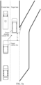
- FIG. 5a and FIG. 5b are schematic diagrams of lane change scenarios of a vehicle according to an embodiment of this application. If a front part of the target vehicle after the expected lane change is adjacent to a rear part of the target obstacle vehicle (as shown in FIG.
- the intelligent driving system may determine the second safe braking distance L b2 corresponding to the target vehicle according to the driving speed v 1 , the second following time interval t h2 , the safe following distance L s , and the spacing distance l 2 (i.e., a spacing distance between the target vehicle 40a and the target obstacle vehicle 40b).
- the intelligent driving system may predefine a minimum gap distance g m1 between the target vehicle 40a and the target obstacle vehicle 40b.
- the second safe braking distance L b2 herein is used for representing a relative position between the target vehicle 40a and the target obstacle vehicle 40b. Therefore, the second safe braking distance L b2 in this embodiment of this application may be negative.
- all the distances referred to in this embodiment of this application may be expressed as a relative position between the two (e.g., two vehicles). Therefore, the calculated distance may be negative. In this case, the negative result is also meaningful, which is not described later.
- the candidate acceleration a 4 in the lane change scenario as shown in FIG. 5a may be determined according to the equation (7), the equation (8), and the equation (9).
- the second safe braking distance L b2 corresponding to the target vehicle is determined according to the driving speed v 3 (i.e., a driving speed of the target obstacle vehicle 40c at the current time), the second following time interval t h2 , the safe following distance L s , and the spacing distance l 2 (i.e., a spacing distance between the target vehicle 40a and the target obstacle vehicle 40c).
- the intelligent driving system may predefine a minimum gap distance g m2 between the target vehicle 40a and the target obstacle vehicle 40c.
- the candidate acceleration a 4 in the lane change scenario as shown in FIG. 5b may be determined according to the equation (7), the equation (10), and the equation (11).
- FIG. 6 is a schematic diagram of a lane change scenario of a vehicle according to an embodiment of this application.
- the target obstacle vehicle may include a first obstacle vehicle 50b (which may be referred to as a putative leader) and a second obstacle vehicle 50c (which may be referred to as a putative follower), and a target vehicle 50a after expected lane change travels between the first obstacle vehicle 50b and the second obstacle vehicle 50c. That is, a rear part of the first obstacle vehicle is adjacent to a front part of the target vehicle after the expected lane change, and a front part of the second obstacle vehicle is adjacent to a rear part of the target vehicle after the expected lane change. In this case, two target obstacle vehicles are provided.
- the process of determining the candidate acceleration a 4 may include: acquiring, by the intelligent driving system, a spacing distance l 3 (at the current time) between the first obstacle vehicle 50b and the second obstacle vehicle 50c, and determining an estimated safe distance L P between the target vehicle 50a after the expected lane change and the first obstacle vehicle 50b (i.e., an optimal spacing distance between the target vehicle 50a after the expected lane change and the first obstacle vehicle) according to the spacing distance l 3 and a vehicle length l 0 of the target vehicle 50a.
- a spacing distance l 4 (at the current time) between the target vehicle 50a and the first obstacle vehicle 50b is acquired.
- a third safe braking distance L b3 corresponding to the target vehicle 50a may be determined according to the spacing distance l 4 and the estimated safe distance L P .
- the intelligent driving system may acquire a driving speed v 4 of the first obstacle vehicle 50b, and determine a candidate acceleration a 4 corresponding to the target vehicle 50a according to the driving speed v 1 , the third safe braking distance L b3 , and the driving speed v 4 .
- the intelligent driving system may acquire a safe following distance L s and a second following time interval t h2 of the target vehicle 50a after the expected lane change, and acquire a driving speed v 5 corresponding to the second obstacle vehicle 50c. Then, a first expected spacing distance g m3 between the first obstacle vehicle 50b and the target vehicle 50a may be determined according to the driving speed v 1 , the safe following distance L s , and the second following time interval t h2 .
- the first expected spacing distance g m3 expresses the same meaning as the minimum gap distance g m1 . That is, an expression of the first expected spacing distance g m3 is shown in the equation (8).
- the intelligent driving system may determine a second expected spacing distance g m4 between the second obstacle vehicle 50c and the target vehicle 50a according to the driving speed v 5 , the safe following distance L s , and the second following time interval t h2 .
- the estimated safe distance L P may be determined according to the spacing distance l 4 and the first expected spacing distance g m3 .
- the first piecewise parameter refers to a sum of the first expected spacing distance g m3 , the second expected spacing distance g m4 , and the vehicle length l 0 .
- the initial predicted lane change acceleration corresponding to the target vehicle is preliminarily planned through the driving parameters of the target vehicle
- an appropriate lane change gap (determined by the target obstacle vehicle) may be determined from the target lane based on the initial predicted lane change acceleration, and after the appropriate lane change gap is determined, the target obstacle vehicle may be taken as a consideration factor (i.e., tracking and avoiding the target obstacle vehicle).
- FIG. 7 is a schematic structural diagram of a data processing apparatus according to an embodiment of this application.
- the data processing apparatus 1 may include: an initial acceleration determination module 11, a position prediction module 12, a target obstacle determination module 13, and a target obstacle determination module 14.
- the initial acceleration determination module 11 is configured to acquire driving parameters of a target vehicle in a current lane, and predict an initial lane change acceleration of the target vehicle according to the driving parameters.
- the position prediction module 12 is configured to predict target position information of the target vehicle according to current position information, a predicted lane change time duration, and the initial lane change acceleration of the target vehicle, the predicted lane change time duration being an estimated time duration taken for the target vehicle to change from the current lane to a target lane.
- the target obstacle determination module 13 is configured to determine, in the target lane, a target obstacle vehicle corresponding to the target vehicle according to the target predicted position information.
- the target lane is a lane to which the target vehicle is expected to change.
- the target obstacle vehicle is a vehicle in the target lane and adjacent to the target vehicle after the expected lane change.
- the target acceleration determination module 14 is configured to determine, according to a predicted position relationship between the target obstacle vehicle and the target vehicle, a target predicted lane change acceleration for instructing the target vehicle to change from the current lane to the target lane; and control, according to the target predicted lane change acceleration, the target vehicle to change from the current lane to the target lane.
- the initial acceleration determination module 11, the position prediction module 12, the target obstacle determination module 13, and the target obstacle determination module 14 may be obtained with reference to step S101 to step S104 in the embodiment corresponding to FIG. 3 . Details are not described here.
- the initial acceleration determination module 11 may include: a parameter acquisition unit 111 and an acceleration generation unit 112.
- the parameter acquisition unit 111 is configured to acquire the driving parameters corresponding to the target vehicle.
- the driving parameters include a maximum target lane speed, a leading car, and a road passing distance.
- the maximum target lane speed is a maximum speed specified in the target lane.
- the leading car is a vehicle guiding a driving route for the target vehicle in the current lane.
- the road passing distance is a length of a passable road in the current lane for the target vehicle.
- the acceleration generation unit 112 is configured to generate the initial predicted lane change acceleration corresponding to the target vehicle according to the maximum target lane speed, the leading car, and the road passing distance.
- parameter acquisition unit 111 and the acceleration generation unit 112 may be obtained with reference to step S101 in the embodiment corresponding to FIG. 3 . Details are not described here.
- the acceleration generation unit 112 may include: a first acceleration determination subunit 1121, a second acceleration determination subunit 1122, a third acceleration determination subunit 1123, and a selection subunit 1124.
- the first acceleration determination subunit 1121 is configured to acquire a driving speed v 1 of the target vehicle and the maximum target lane speed of the target lane, and determine a first limited acceleration corresponding to the target vehicle according to the driving speed v 1 and the maximum target lane speed.
- the second acceleration determination subunit 1122 is configured to generate a braking acceleration corresponding to the target vehicle according to the driving speed v 1 and the road passing distance, and determine a second limited acceleration corresponding to the target vehicle according to the braking acceleration.
- the third acceleration determination subunit 1123 is configured to determine a first safe braking distance corresponding to the target vehicle according to a driving speed v 2 of the leading car, and determine a third limited acceleration corresponding to the target vehicle according to the first safe braking distance, the driving speed v 1 , a target following speed, and an estimated following duration.
- the target following speed is a smaller value of the maximum target lane speed and the driving speed v 2 .
- the selection subunit 1124 is configured to determine a minimum value of the first limited acceleration, the second limited acceleration, and the third limited acceleration as the initial predicted lane change acceleration corresponding to the target vehicle.
- the second acceleration determination subunit 1122 is further configured to:
- the third acceleration determination subunit 1123 is further configured to:
- first acceleration determination subunit 1121 the second acceleration determination subunit 1122, the third acceleration determination subunit 1123, and the selection subunit 1124 may be obtained with reference to step S101 in the embodiment corresponding to FIG. 3 . Details are not described here.
- the target obstacle determination module 13 may include: an obstacle position prediction unit 131, a predicted distance acquisition unit 132, and a traffic vehicle selection unit 133.
- the obstacle position prediction unit 131 is configured to acquire, from the target lane, vehicle driving speeds respectively corresponding to N traffic vehicles within a reference distance range, and determine predicted position information respectively corresponding to the N traffic vehicles according to the vehicle driving speeds and the predicted lane change time duration.
- N is a positive integer.
- the predicted distance acquisition unit 132 is configured to acquire predicted distances between the target vehicle and the N traffic vehicles respectively according to the target predicted position information and the predicted position information respectively corresponding to the N traffic vehicles.
- the traffic vehicle selection unit 133 is configured to determine one or more traffic vehicles at a minimum predicted distance from the target vehicle as the target obstacle vehicle corresponding to the target vehicle.
- the obstacle position prediction unit 131 the predicted distance acquisition unit 132, and the traffic vehicle selection unit 133 may be obtained with reference to step 5103 in the embodiment corresponding to FIG. 3 . Details are not described here.
- the target acceleration determination module 14 may include: a candidate acceleration determination unit 141, an acceleration selection unit 142, and a lane change unit 143.
- the candidate acceleration determination unit 141 is configured to determine a candidate acceleration corresponding to the target vehicle according to the predicted position relationship between the target obstacle vehicle and the target vehicle.
- the acceleration selection unit 142 is configured to determine a minimum value of the candidate acceleration, the second limited acceleration, and the third limited acceleration as the target predicted lane change acceleration corresponding to the target vehicle.
- the lane change unit 143 is configured to control the target vehicle to change from the current lane to the target lane according to the target predicted lane change acceleration.
- step S104 Specific function implementations of the candidate acceleration determination unit 141, the acceleration selection unit 142, and the lane change unit 143 may be obtained with reference to step S104 in the embodiment corresponding to FIG. 3 . Details are not described here.
- one target obstacle vehicle is provided.
- the candidate acceleration determination unit 141 may include: a spacing distance acquisition subunit 1411, a first braking distance determination subunit 1412, and a first determination subunit 1413.
- the spacing distance acquisition subunit 1411 is configured to acquire a driving speed v 3 corresponding to the target obstacle vehicle, and a spacing distance l 2 between the target obstacle vehicle and the target vehicle.
- the first braking distance determination subunit 1412 is configured to determine a second safe braking distance corresponding to the target vehicle according to the spacing distance l 2 .
- the first determination subunit 1413 is configured to determine the candidate acceleration corresponding to the target vehicle according to the driving speed v 1 , the second safe braking distance, and the driving speed v 3 .
- the first braking distance determination subunit 1412 may be further configured to:
- the spacing distance acquisition subunit 1411 the first braking distance determination subunit 1412, and the first determination subunit 1413 may be obtained with reference to step S104 in the embodiment corresponding to FIG. 3 . Details are not described here.
- the target obstacle vehicle includes a first obstacle vehicle and a second obstacle vehicle, a rear part of the first obstacle vehicle is adjacent to the front part of the target vehicle after the expected lane change, and a front part of the second obstacle vehicle is adjacent to the rear part of the target vehicle after the expected lane change.
- the candidate acceleration determination unit 141 may include: an estimated safe distance determination subunit 1414, a second braking distance determination subunit 1415, and a second determination subunit 1416.
- the estimated safe distance determination subunit 1414 is configured to acquire a spacing distance l 3 between the first obstacle vehicle and the second obstacle vehicle, and determine an estimated safe distance between the target vehicle after the expected lane change and the first obstacle vehicle according to the spacing distance l 3 and a vehicle length of the target vehicle.
- the second braking distance determination subunit 1415 is configured to acquire a spacing distance l 4 between the target vehicle and the first obstacle vehicle, and determine a third safe braking distance corresponding to the target vehicle according to the spacing distance l 4 and the estimated safe distance.
- the second determination subunit 1416 is configured to acquire a driving speed v 4 of the first obstacle vehicle, and determine the candidate acceleration corresponding to the target vehicle according to the driving speed v 1 , the third safe braking distance, and the driving speed v 4 .
- the estimated safe distance determination subunit 1414 may be further configured to:
- the estimated safe distance determination subunit 1414 may be obtained with reference to step S104 in the embodiment corresponding to FIG. 3 . Details are not described here.
- the spacing distance acquisition subunit 1411, the first braking distance determination subunit 1412, and the first determination subunit 1413 perform corresponding operations
- the estimated safe distance determination subunit 1414, the second braking distance determination subunit 1415, and the second determination subunit 1416 suspend the operations.
- the spacing distance acquisition subunit 1411, the first braking distance determination subunit 1412, and the first determination subunit 1413 suspend the operations.
- the initial predicted lane change acceleration corresponding to the target vehicle is preliminarily planned through the driving parameters of the target vehicle
- an appropriate lane change gap (determined by the target obstacle vehicle) may be determined from the target lane based on the initial predicted lane change acceleration, and after the appropriate lane change gap is determined, the target obstacle vehicle may be taken as a consideration factor (i.e., tracking and avoiding the target obstacle vehicle).
- FIG. 8 is a schematic structural diagram of a computer device according to an embodiment of this application.
- the computer device 1000 may include: a processor 1001, a network interface 1004, and a memory 1005.
- the computer device 1000 may further include: a user interface 1003 and at least one communication bus 1002.
- the communication bus 1002 is configured to implement connection and communication between these components.
- the user interface 1003 may include a display and a keyboard.
- the user interface 1003 may further include a standard wired interface and a standard wireless interface.
- the network interface 1004 may include a standard wired interface and a standard wireless interface (such as a Wi-Fi interface).
- the memory 1005 may be a high-speed RAM, or may be a non-volatile memory, for example, at least one magnetic disk memory. In some embodiments, the memory 1005 may alternatively be at least one storage apparatus located away from the processor 1001. As shown in FIG. 8 , the memory 1005 used as a computer-readable storage medium may include an operating system, a network communication module, a user interface module, and a device-control application program.
- the network interface 1004 may provide a network communication function.
- the user interface 1003 is configured mainly to provide an input interface for a user.
- the processor 1001 may be configured to invoke a device control application stored in the memory 1005 to implement:
- the computer device 1000 described in this embodiment of this application may implement the descriptions of the data processing method in the embodiment corresponding to FIG. 3 , or the descriptions of the data processing apparatus 1 in the embodiment corresponding to FIG. 7 . Details are not described herein again. In addition, the description of beneficial effects of the same method is not described herein again.
- an embodiment of this application further provides a computer-readable storage medium.
- the computer-readable storage medium stores a computer program executed by the data processing apparatus 1 mentioned above, and the computer program includes program instructions.
- the processor can perform the descriptions of the data processing method in the embodiment corresponding to FIG. 3 . Therefore, details are not described herein again.
- the description of beneficial effects of the same method is not described herein again.
- an embodiment of this application further provides a computer program product or a computer program.
- the computer program product or the computer program may include computer instructions, and the computer instructions may be stored in a computer-readable storage medium.
- a processor of a computer device reads the computer instructions from the computer-readable storage medium, and may execute the computer instructions, to cause the computer device to perform the descriptions of the data processing method in the embodiment corresponding to FIG. 3 . Therefore, details are not described herein again. In addition, the description of beneficial effects of the same method is not described herein again. For technical details that are not disclosed in embodiments of the computer program product or computer program of this application, refer to the descriptions of the method embodiments of this application.
- the computer program may be stored in a computer-readable storage medium. During execution of the program, the processes of the foregoing method embodiments may be included.
- the foregoing storage medium may be a magnetic disk, an optical disc, a read-only memory (ROM), a random access memory (RAM), or the like.
Landscapes
- Engineering & Computer Science (AREA)
- Physics & Mathematics (AREA)
- General Physics & Mathematics (AREA)
- Automation & Control Theory (AREA)
- Transportation (AREA)
- Mechanical Engineering (AREA)
- Human Computer Interaction (AREA)
- Life Sciences & Earth Sciences (AREA)
- Atmospheric Sciences (AREA)
- Traffic Control Systems (AREA)
- Control Of Driving Devices And Active Controlling Of Vehicle (AREA)
Abstract
Description
- This application claims priority to
Chinese Patent Application No.202010979552.7, entitled "VEHICLE-BASED DATA PROCESSING METHOD AND APPARATUS, DEVICE, AND MEDIUM" filed on September 17, 2020 - This application relates to the technical field of intelligent driving, and in particular, to a data processing method and apparatus, a device, and a medium.
- A driverless vehicle is an intelligent vehicle that senses a road environment through an in-vehicle sensor system, automatically plans a driving route, and controls the vehicle to reach a predetermined destination. The driverless vehicle may achieve a purpose of autonomous driving by relying on a computer-system-based intelligent pilot in the vehicle.
- In the related art, when changing lanes, the driverless vehicle generally requires surrounding vehicles to cooperate and give way in order to obtain enough lane change space and realize safe lane change of the driverless vehicle. However, in congestion scenarios, the surrounding vehicles cannot cooperate with and give way to the driverless vehicle. As a result, the driverless vehicle cannot find a suitable lane change opportunity, which leads to failure in the lane change of the driverless vehicle.
- An embodiment of this application provides a data processing method, performed by a computer device, the method including:
- acquiring driving parameters of a target vehicle in a current lane, and generating an initial predicted lane change acceleration corresponding to the target vehicle according to the driving parameters;
- generating target predicted position information corresponding to the target vehicle according to current position information, a predicted lane change time duration, and the initial predicted lane change acceleration of the target vehicle, the predicted lane change time duration being an estimated time duration taken for the target vehicle to change from the current lane to a target lane;
- determining a target obstacle vehicle in the target lane corresponding to the target vehicle according to the target predicted position information; the target lane being a lane to which the target vehicle is expected to change, the target obstacle vehicle being a vehicle in the target lane and adjacent to the target vehicle after the expected lane change;
- determining, a target predicted lane change acceleration for instructing the target vehicle to change from the current lane to the target lane according to a predicted position relationship between the target obstacle vehicle and the target vehicle; and
- controlling, according to the target predicted lane change acceleration, the target vehicle to change from the current lane to the target lane.
- An embodiment of this application provides a data processing apparatus, including:
- an initial acceleration determination module configured to acquire driving parameters of a target vehicle in a current lane, and predict an initial lane change acceleration of the target vehicle according to the driving parameters;
- a position prediction module configured to predict target position information of the target vehicle according to current position information, a predicted lane change time duration, and the initial lane change acceleration of the target vehicle, the predicted lane change time duration being an estimated time duration taken for the target vehicle to change from the current lane to a target lane;
- a target obstacle determination module configured to determine a target obstacle vehicle corresponding to the target vehicle in the target lane according to the target predicted position information; the target lane being a lane to which the target vehicle is expected to change, the target obstacle vehicle being a vehicle in the target lane and adjacent to the target vehicle after the expected lane change; and
- a target acceleration determination module configured to determine a target predicted lane change acceleration for instructing the target vehicle to change from the current lane to the target lane; and control, according to the target predicted lane change acceleration according to a predicted position relationship between the target obstacle vehicle and the target vehicle.
- An aspect of the embodiments of this application provides a computer device, including a memory and a processor, the memory storing a computer program, the computer program, when executed by the processor, causing the processor to perform the steps of the method in one aspect of the embodiments of this application.
- An aspect of the embodiments of this application provides a computer-readable storage medium, storing a computer program, the computer program including program instructions, the program instructions, when executed by a processor, implementing the steps of the method in one aspect of the embodiments of this application.
- According to an aspect of this application, a computer program product or a computer program is provided, the computer program product or the computer program including computer instructions, the computer instructions being stored in a computer-readable storage medium. A processor of a computer device reads the computer instructions from the computer-readable storage medium, and the processor executes the computer instructions, so that the computer device performs the method in the various implementations of one aspect described above.
- To describe the technical solutions of the embodiments of this application or the related art more clearly, the following briefly introduces the accompanying drawings required for describing the embodiments or the related art. The accompanying drawings in the following description show merely some embodiments of this application, and a person of ordinary skill in the art may still derive other drawings from these accompanying drawings without creative efforts.
-
FIG. 1a is a diagram of a system architecture to which a data processing method according to an embodiment of this application applies; -
FIG. 1b is a schematic structural diagram of an intelligent driving system according to an embodiment of this application; -
FIG. 2a andFIG. 2b are schematic diagrams of lane change scenarios of a driverless vehicle according to an embodiment of this application; -
FIG. 3 is a schematic flowchart of a data processing method according to an embodiment of this application; -
FIG. 4 is a schematic diagram of determining a target obstacle vehicle according to an embodiment of this application; -
FIG. 5a andFIG. 5b are schematic diagrams of lane change scenarios of a vehicle according to an embodiment of this application; -
FIG. 6 is a schematic diagram of a lane change scenario of a vehicle according to an embodiment of this application; -
FIG. 7 is a schematic structural diagram of a data processing apparatus according to an embodiment of this application; and -
FIG. 8 is a schematic structural diagram of a computer device according to an embodiment of this application. - The technical solutions in the embodiments of this application are clearly and completely described in the following with reference to the accompanying drawings in the embodiments of this application. Apparently, the described embodiments are merely some rather than all of the embodiments of this application. All other embodiments obtained by a person of ordinary skill in the art based on the embodiments of this application without creative efforts shall fall within the protection scope of this application.
- This application relates to driverless vehicles (also referred to as wheeled mobile robots or autonomous vehicles) in intelligent driving technologies. A driverless vehicle is an intelligent vehicle that senses a road environment through an in-vehicle sensor system, automatically plans a driving route, and controls the vehicle to reach a predetermined destination. The driverless vehicle may use an in-vehicle sensor to sense environments around the vehicle, and control the vehicle's steering and speed according to sensed roads, vehicle positions, and obstacle information, so that the vehicle can safely and reliably travel on the roads. The driverless vehicle integrates many technologies such as automatic control, system architecture, artificial intelligence, and vision computing, and is a highly developed product of computer science, pattern recognition, and intelligent control technologies.
- In congestion scenarios, if the surrounding vehicles cannot cooperate with and give way to the driverless vehicle, the driverless vehicle cannot find a suitable lane change opportunity, which leads to failure in the lane change of the driverless vehicle. Based on this, embodiments of this application provide a vehicle lane change method and apparatus, a device, and a medium, which can improve a lane change success rate of a vehicle.
-
FIG. 1a is asystem architecture 100 to which a vehicle lane change method according to an embodiment of this application applies. As shown inFIG. 1a , asystem architecture 100 may include one or more ofterminal devices network 104, and aserver 105. Thenetwork 104 is configured to provide a medium of a communication link between theserver 105 and theterminal devices network 104 may include various connection types, such as a wired or wireless communication link, or a fiber optic cable. Theterminal devices server 105 may be a server cluster including a plurality of servers. - The vehicle lane change method according to this embodiment of this application is generally performed by the
terminal devices server 105, which is not specially limited in this exemplary embodiment. - Referring to
FIG. 1b, FIG. 1b is a schematic structural diagram of an intelligent driving system according to an embodiment of this application. As shown inFIG. 1b , the intelligent driving system is generally mounted on a conventional vehicle to build the whole system. The intelligent driving system may include a hardware part and a software part. The hardware part may include a sensor, a signal communication module, a brake, and the like. The software part may include a sensing module, a planning module, a control module, and the like, which may be mounted in theterminal device 101 or theterminal device 102 shown inFIG. 1a . - The sensor may be configured to acquire a lot of information about surroundings, such as positions, speeds, and possible behaviors of obstacles (the obstacles herein may refer to other vehicles, pedestrians, cones, guardrails, etc. around the driverless vehicle), travelable regions, and traffic rules. The sensor may include, but is not limited to, a camera, a lidar, and a millimeter wave radar. The camera may be configured to acquire image information, and may identify pedestrians, cars, trees, traffic lights, signal boards, and so on from the image information through the sensing module of the software part. That is, obstacles and traffic signals may be detected according to the image information. The lidar may be configured to acquire laser scanning reflection data, and may identify obstacles such as pedestrians, cars, and trees from the laser scanning reflection data through the sensing module. That is, obstacles may be detected according to the laser scanning reflection data. The millimeter wave radar may be configured to acquire reflection data, may identify obstacles and measure distances according to the reflection data, and may achieve a purpose of assisting obstacle avoidance. In other words, the intelligent driving system may sense surroundings of the driverless vehicle in real time according to data acquired by the sensor.
- In order to achieve a certain goal, the planning module may make some purposeful decisions for the driverless vehicle. For the driverless vehicle, the goal generally refers to getting from an origin to a destination and avoiding obstacles, and constantly optimizing driving trajectories and behaviors to ensure safety and comfort of passengers. Planning may include task planning, behavior planning, and motion planning. Path planning may also be referred to as routing. A role of the task planning may be simply understood as navigation inside the intelligent driving system, that is, to guide, on a macro level, the driverless vehicle to travel from a starting point to a destination point according to a road. The behavior planning is also referred to as decision making. The behavior planning may be responsible for determining next decision to be executed by the driverless vehicle according to a goal of the path planning and a current local situation (e.g., positions and behaviors of other vehicles and pedestrians, current traffic rules, etc.). The behavior planning may be understood as a co-driver of the vehicle, which directs, according to a goal and a current traffic situation, a driver whether to follow or overtake, stop and wait for pedestrians to pass or bypass pedestrians, and the like. The motion planning may include path planning and speed planning. A role of the motion planning may be understood as specifically solving the problem of how the driverless vehicle travels from a point A to a point B in a small spatio-temporal region. For example, an intermediate waypoint from the point A to the point B within a short time t may be planned, including selecting specific waypoints, and a speed, an orientation, and an acceleration of the driverless vehicle when the driverless vehicle reaches each waypoint.
- The control module is the lowest level of the intelligent driving system and may be configured to implement the above planned behaviors (e.g., obstacle avoidance, lane change, etc.). The control module may transmit an execution instruction to the brake of the hardware part to control execution of power (throttle and gear), chassis (steering and braking) and electronic and electrical systems of the driverless vehicle, so as to realize the control over a speed and a direction of the driverless vehicle.
- The signal communication module may include vehicle-to-vehicle (V2V) communication. The V2V communication refers to wireless-based data transmission between motor vehicles. To prevent accidents, the V2V communication transmits vehicle positions and speed information to other vehicles via a dedicated network. The signal communication module may exchange data with the sensing module. Vehicle positions and speed information of the other vehicles may be sensed in real time through the sensing module. In addition, vehicle positions and speed information of the current driverless vehicle may also be transmitted to the other vehicles through the signal communication module. The sensing module of the driverless vehicle may take autonomous measures, such as braking and deceleration, based on the information received.
- This application relates to the behavior planning in the intelligent driving system, and mainly to the issue of speed planning in lane change in driverless congestion scenarios.
- Referring to
FIG. 2a andFIG. 2b together,FIG. 2a andFIG. 2b are schematic diagrams of lane change scenarios of a driverless vehicle according to an embodiment of this application. Taking a scenario in which a driverless vehicle joins a highway or a main road as an example, avehicle 10a shown inFIG. 2a is the driverless vehicle. When thevehicle 10a is located at an entrance to the highway or main road, thevehicle 10a has to change lanes to join the highway or main road. Avehicle 10b shown inFIG. 2a refers to a leader traveling in the same lane as thevehicle 10a and in front of thevehicle 10a (thevehicle 10b and thevehicle 10a are adjacent vehicles in a current lane). Avehicle 10c, avehicle 10d, and a vehicle 10e are vehicles traveling in a target lane respectively. For thevehicle 10a that is about to change lanes, thevehicle 10c, thevehicle 10d, and the vehicle 10e are obstacles. - As shown in
FIG. 2a , a travelable region of thevehicle 10a in the current lane is a region L1. That is, thevehicle 10a needs to change to the target lane before traveling to an endpoint of the region L1 to prevent collision. During the lane change, thevehicle 10a may choose, according to a length of the region L1 in the current lane, a driving speed of thevehicle 10a, a driving speed of thevehicle 10b, and speeds and positions of moving vehicles in the target lane (e.g., positions and speeds of thevehicle 10c, thevehicle 10d, and the vehicle 10e in the target lane), a proper lane change gap from the target lane, that is, choose to jam between which two vehicles in the target lane. As shown inFIG. 2a , the target lane has 4 gaps for thevehicle 10a to select. The 4 gaps are a front region of thevehicle 10c, a region L2 between thevehicle 10c and thevehicle 10d, a region L3 between thevehicle 10d and the vehicle 10e, and a rear region L4 of the vehicle 10e respectively. - If the
vehicle 10a selects the region L2 as a gap for the lane change, thevehicle 10a further needs to perform speed planning according to information such as a spacing distance between thevehicle 10c and thevehicle 10d, a safe distance between vehicles, and driving speeds respectively corresponding to thevehicle 10c and thevehicle 10d. A safe lane change from the current lane to the target lane is realized by changing the speed of thevehicle 10a. - When the driverless vehicle is located at the entrance to the highway or main road, a
vehicle 20a shown inFIG. 2b is the driverless vehicle that is about to change lanes to exit the highway or main road. That is, thevehicle 20a needs to change from the current lane to the target lane to achieve a purpose of exiting the highway or main road. As shown inFIG. 2b , thevehicle 20b refers to a leader traveling in the same lane as thevehicle 20a and in front of thevehicle 20a (thevehicle 20b and thevehicle 20a are adjacent vehicles in a current lane). Avehicle 20c and avehicle 20d are vehicles traveling in the target lane respectively. For thevehicle 20a that is about to change lanes, thevehicle 20c and thevehicle 20d are obstacles. - During the lane change, the
vehicle 20a first needs to choose a proper lane change gap from the target lane, that is, choose to jam between which two vehicles in the target lane. Thevehicle 20a may choose the proper lane change gap from the target lane according to information such as a driving speed of thevehicle 20a, a driving speed of thevehicle 20b, a driving speed of thevehicle 20c, and a driving speed of thevehicle 20d. As shown inFIG. 2b , the target lane has 3 gaps for thevehicle 20a to select. The 3 gaps are a front region L6 of thevehicle 20c (in practical applications, thevehicle 20c herein has completely exited the highway or main road and is already traveling in the target lane, so the region L6 herein can be ignored), a region L5 between thevehicle 20c and thevehicle 20d, and a rear region L7 of thevehicle 20d respectively. - If the
vehicle 20a selects the region L5 as a gap for the lane change, thevehicle 20a further needs to perform speed planning according to information such as a spacing distance between thevehicle 20c and thevehicle 20d, a safe distance between vehicles, and driving speeds respectively corresponding to thevehicle 20c and thevehicle 20d. A safe lane change from the current lane to the target lane is realized by changing the speed of thevehicle 20a. - A specific process of performing speed planning on the
vehicle 10a and thevehicle 20a may be obtained with reference to embodiments corresponding toFIG. 3 to FIG. 6 below. - Further, referring to
FIG. 3, FIG. 3 is a schematic flowchart of a data processing method according to an embodiment of this application. The method is performed by a computer device. The computer device may be a terminal device shown inFIG. 1a or aserver 105 inFIG. 1a . As shown inFIG. 3 , the data processing method may include the following steps. - Step S101. Acquire driving parameters of a target vehicle in a current lane, and predict an initial lane change acceleration of the target vehicle according to the driving parameters.
- Specifically, the intelligent driving system may perform coarse speed planning according to driving parameters (also referred to as environmental conditions of the target vehicle) of the target vehicle (i.e., a driverless vehicle needing to change lanes, such as the
vehicle 10a in the embodiment corresponding toFIG. 2a , which may be referred to as an Ego car) to predict the initial lane change acceleration corresponding to the target vehicle. The driving parameters may include a maximum target lane speed vm, a leading car (also referred to as a leader), and a road passing distance Lm (m). The maximum target lane speed vm refers to a maximum speed specified in the target lane. The target lane refers to a lane to which the target vehicle is expected to change. For example, when the target lane is a lane in an expressway, the maximum target lane speed vm may be 120 m/s which is the maximum speed specified in the expressway. The leading car refers to a vehicle guiding a driving route for the target vehicle in the current lane, that is, an environmental vehicle in the current lane and traveling in front of and closest to the target vehicle. The road passing distance Lm refers to a length of a passable road in the current lane for the target vehicle, for example, a length of the region L1 in the embodiment corresponding toFIG. 2a . - Further, the intelligent driving system may acquire a current driving speed v1 of the target vehicle, and determine a first limited acceleration a1 corresponding to the target vehicle according to the driving speed v1 and the maximum target lane speed vm. The first limited acceleration a1 may be expressed as:

where amax is used for denoting a maximum acceleration designed by the target vehicle, i.e., a maximum value of the first limited acceleration a1 is amax. The equation (1) is a piecewise function representation of the first limited acceleration a1, and a consideration factor in the equation (1) is a current traffic flow speed of the target lane. When the driving speed v1 of the target vehicle is less than a difference between the maximum target lane speed vm and 2.0, the first limited acceleration a1 may be designed to be the maximum acceleration amax (m/s2). When the driving speed v1 of the target vehicle is less than a difference between the maximum target lane speed vm and 0.5 and greater than or equal to the difference between the maximum target lane speed vm and 2.0, the first limited acceleration a1 may be designed to be 0.5 m/s2. When the driving speed v1 of the target vehicle is less than a sum of the maximum target lane speed vm and 0.5 and greater than or equal to the difference between the maximum target lane speed vm and 0.5, the first limited acceleration a1 may be designed to be 0. That is, the driving speed v1 is continued for uniform motion. When the driving speed v1 of the target vehicle is greater than or equal to the sum of the maximum target lane speed vm and 0.5, the first limited acceleration a1 may be designed to be -(v1 - vm)/3.0. - In the embodiments of this application, all the driving speeds referred to may be instantaneous speeds in units of m/s, all the accelerations referred to are in units of m/s2, and all the distances referred to are in units of m. Details are not described in the subsequent description.
- In some embodiments, in the lane change scenario, the intelligent driving system further needs to consider the influence of the road passing distance Lm. The target vehicle remains traveling in the current lane when the target vehicle searches for the right time to change lanes. When the target vehicle does not find a suitable lane change opportunity and gradually approaches the endpoint of the current lane, the intelligent driving system needs to control the target vehicle to slow down. Therefore, the intelligent driving system may generate a braking acceleration ar corresponding to the target vehicle according to the driving speed v1 and the road passing distance Lm, and determine a second limited acceleration a2 corresponding to the target vehicle according to the braking acceleration ar.
- The braking acceleration ar may refer to an acceleration used by the target vehicle to slow down. The intelligent driving system may acquire a road endpoint speed vmin of the target vehicle in the current lane, and acquire a square difference between the driving speed v1 and the road endpoint speed vmin. The road endpoint speed vmin is a minimum speed at which the target vehicle travels to the endpoint of the current lane. For example, the road endpoint speed may be a minimum speed at which the target vehicle travels to the endpoint of the current lane when the target vehicle is located at an entrance to a highway or main road and needs to join the main road. Alternatively, in another example, the road endpoint speed may be a minimum speed at which the target vehicle exits the highway or main road or the target vehicle travels to an exit from a current road (for example, the road endpoint speed vmin may be 3.0 m/s, or the road endpoint speed vmin may be 0, or the road endpoint speed vmin may be a preset constant parameter). Then, the braking acceleration ar corresponding to the target vehicle may be determined according to a ratio of the square difference to the road passing distance Lm. The braking acceleration ar may be expressed as:

- The braking acceleration ar may be calculated according to the equation (2). The second limited acceleration a2 may be expressed as:

- The equation (3) is a piecewise function representation of the second limited acceleration a2. When the braking acceleration ar is less than -1.0 m/s2, the second limited acceleration a2 may be designed to be -1.0 m/s2. When the braking acceleration ar is less than - 0.5 m/s2 and greater than or equal to -1.0 m/s2, the second limited acceleration a2 may be designed to be -0.5 m/s2. When the braking acceleration ar is less than 0 and greater than or equal to - 0.5m/s2, the second limited acceleration a2 may be designed to be 0. That is, the driving speed v1 is continued for uniform motion. When the braking acceleration ar is greater than or equal to 0, the second limited acceleration a2 may be designed to be amax.
- In some embodiments, in the lane change scenario, the intelligent driving system further needs to consider the influence of the leading car in the current lane. When a leading car exists in the current lane for the target vehicle, the target vehicle may have to take more radical measures (such as shortening a following distance with the leading car) to accelerate the lane change in order to realize the lane change. Therefore, the intelligent driving system may acquire a driving speed v2 of the leading car, determine a first safe braking distance Lb1 corresponding to the target vehicle according to the driving speed v2, and then determine a third limited acceleration a3 corresponding to the target vehicle according to the first safe braking distance Lb1, the driving speed v1, a target following speed vf, and an estimated following duration tf. The target following speed vf is a smaller value of the maximum target lane speed vm and the driving speed v2, i.e., vf = min (v2, vm). The estimated following duration tf is a preset constant parameter (e.g., tf=3-4 s) and used for estimating a duration in which the target vehicle follows the leading car in the current lane. The first safe braking distance Lb1 may be used for representing a distance that can be traveled by the target vehicle in the current lane while keeping a safe following distance from the leading car.
- A process of determining the first safe braking distance Lb1 may include: acquiring, by the intelligent driving system, a first following time interval th1 (the first following time interval th1 may be a preset constant parameter and used for representing a duration in which the target vehicle at the current driving speed v1 keeps a minimum safe distance from the leading car, e.g., th1 = 0.5 - 0.8 s) between the target vehicle and the leading car, and determining a target following distance according to the target following speed vf and the first following time interval th1; and acquiring a spacing distance l1 (a spacing distance at the current time) between the target vehicle and the leading car, and determining a difference between the spacing distance l1 and the target following distance as the first safe braking distance Lb1. The first safe braking distance Lb1 may be expressed as:

- The first safe braking distance Lb1 may be calculated from the equation (4). In this case, the third limited acceleration a3 may be expressed as:

- After obtaining the first limited acceleration a1, the second limited acceleration a2, and the third limited acceleration a3, the intelligent driving system may determine a minimum value of the first limited acceleration a1, the second limited acceleration a2, and the third limited acceleration a3 as the initial predicted lane change acceleration


- Step S102. Predict target position information of the target vehicle according to current position information, a predicted lane change time duration, and the initial predicted lane change acceleration of the target vehicle.
- Specifically, the intelligent driving system may estimate a relative position relationship between the target vehicle and a surrounding obstacle vehicle after a future period of time (e.g., 3-5s) according to the initial predicted lane change acceleration, and may select an appropriate lane change gap for lane change preparations according to the relative position relationship. 3-5s may be expressed as the predicted lane change time duration, that is, a duration taken by the target vehicle to change from the current lane to the target lane. The intelligent driving system may acquire current position information of the target vehicle, and determine target predicted position information of the target vehicle after the predicted lane change time duration according to the current position information, the predicted lane change time duration, and the initial predicted lane change acceleration


where s(tp) in the equation (6) denotes the target predicted position information corresponding to the target vehicle, s(t0) denotes the current position information of the target vehicle, and tp denotes the predicted lane change time duration. - The position information (including the current position information and the target predicted position information, and predicted position information of an obstacle vehicle mentioned later) referred to in this embodiment of this application may refer to coordinate information expressed by a Cartesian coordinate system or coordinate information expressed by a Frenet coordinate system. The Frenet coordinate system is a way of representing positions of a road more intuitively than conventional x, y Cartesian coordinate systems. In the Frenet coordinate system, positions of the vehicle on the road may be described using variables s and d, the s coordinate represents a distance along the road (also referred to as a longitudinal position), and the d coordinate represents a left-right position on the road (also referred to as a transverse position). In this embodiment of this application, the Frenet coordinate system is taken as an example to describe position information of the target vehicle and the obstacle vehicle. The position information in this embodiment of this application may refer to longitudinal position information in the Frenet coordinate system, i.e., the distance along the road.
- Step S103. Determine, in the target lane, a target obstacle vehicle corresponding to the target vehicle according to the target predicted position information; the target obstacle vehicle being a vehicle in the target lane and adjacent to the target vehicle after the expected lane change.
- Specifically, the intelligent driving system may acquire obstacle vehicles in an environment around the target vehicle, estimate predicted distances between the obstacle vehicles and the target vehicle after the predicted lane change time duration tp, and then determine a target obstacle vehicle corresponding to the target vehicle in the target lane. The target obstacle vehicle may refer to a vehicle in the target lane and adjacent to the target vehicle after the expected lane change.
- Further, the intelligent driving system may acquire, from the target lane, vehicle driving speeds respectively corresponding to N traffic vehicles within a reference distance range, and determine predicted position information respectively corresponding to the N traffic vehicles according to the vehicle driving speeds and the predicted lane change time duration. N is a positive integer. Then, the intelligent driving system may acquire predicted distances between the target vehicle and the N traffic vehicles respectively according to the target predicted position information and the predicted position information respectively corresponding to the N traffic vehicles, and determine one or more traffic vehicles at a minimum predicted distance from the target vehicle as the target obstacle vehicle corresponding to the target vehicle. It may be understood that the intelligent driving system acquires the predicted position information of the obstacle vehicle to select an appropriate lane change gap. Since the target vehicle needs to change from the current lane to the target lane, the intelligent driving system may acquire only relevant information (including driving speeds, current positions, predicted positions after the predicted lane change time duration, etc.) of the N traffic vehicles within the reference distance range of the target lane. The reference distance range herein may refer to a determined range of the target obstacle vehicle. For example, the reference distance range may be a range of 100 m before and after the current position information of the target vehicle, etc. The N traffic vehicles in the target lane may be regarded as moving at a constant speed in an expected lane change time duration. In this case, the predicated position information of each traffic vehicle in the target lane may be expressed as a current position of the traffic vehicle plus a distance traveled at a constant speed in the predicted lane change time duration. By calculating a predicated distance between the target vehicle and each traffic vehicle, a front obstacle and a rear obstacle that are closest to the target predicted position information s(tp) may be selected as the target obstacle vehicles.
- Referring to
FIG. 4 together,FIG. 4 is a schematic diagram of determining a target obstacle vehicle according to an embodiment of this application. Avehicle 30a shown inFIG. 4 is a driverless vehicle needing to change lanes. A position of thevehicle 30a at the current time (i.e., time t0) is a position A of the current lane. A longitudinal position of the position A in the Frenet coordinate system may be represented by s(t0). Target predicted position information of thevehicle 30a may be calculated as s(tp) according to the calculated initial predicted lane change acceleration
vehicle 30a. That is, thevehicle 30a may travel from the position A to a position B in the current lane within the predicted lane change time duration tp. A longitudinal position corresponding to the position B is s(tp). s(tp) is the target predicted position information of thevehicle 30a after the predicted lane change time duration tp. - The intelligent driving system may acquire a
vehicle 30b, avehicle 30c, and avehicle 30d within the reference distance range from the target lane. At the time t0, thevehicle 30b is at a position G in the target lane, thevehicle 30c is at a position D in the target lane, and thevehicle 30d is at a position C in the target lane. Driving speeds of thevehicle 30b, thevehicle 30c, and thevehicle 30d at the time t0 are acquired respectively. Predicted position information respectively corresponding to thevehicle 30b, thevehicle 30c, and thevehicle 30d after the predicted lane change time duration tp (herein, it is assumed that thevehicle 30b, thevehicle 30c, and thevehicle 30d move at a constant speed in the predicted lane change time duration tp) according to the driving speeds at the time t0 and the predicted lane change time duration tp. As shown inFIG. 4 , thevehicle 30c travels from the position D to a position F in the target lane in the predicted lane change time duration tp. A longitudinal position corresponding to the position F is s3 (i.e., predicted position information corresponding to thevehicle 30c). Thevehicle 30d travels from the position C to a position E in the target lane in the predicted lane change time duration tp. A longitudinal position corresponding to the position E is s2 (i.e., predicted position information corresponding to thevehicle 30d). By respectively calculating predicted distances between the longitudinal position s(tp) and the predicted position information corresponding to thevehicle 30b, thevehicle 30c, and thevehicle 30d, it may be determined that the distance between the longitudinal position s2 and the longitudinal position s(tp) is minimum, and the longitudinal position s2 is lower than the longitudinal position s(tp). Then, thevehicle 30d corresponding to the longitudinal position s2 may be determined as a target obstacle vehicle corresponding to thevehicle 30a (after the predicted lane change time duration tp, thevehicle 30d is located behind thevehicle 30a), and then thevehicle 30c may also be determined as a target obstacle vehicle corresponding to thevehicle 30a (after the predicted lane change time duration tp, thevehicle 30c is a vehicle in front of and closest to thevehicle 30a). - Step S104. Determine, according to a predicted position relationship between the target obstacle vehicle and the target vehicle, a target predicted lane change acceleration for instructing the target vehicle to change from the current lane to the target lane.
-
Step S 105. Control, according to the target predicted lane change acceleration, the target vehicle to change from the current lane to the target lane. - When the vehicle lane change method according to this embodiment of this application is performed by a server, the server transmits a control instruction to the intelligent driving system in the target vehicle to cause the intelligent driving system to control the target vehicle to change from the current lane to the target lane.
- Specifically, it may be understood that the initial predicted lane change acceleration


- The intelligent driving system may determine a candidate acceleration a4 corresponding to the target vehicle according to the predicted position relationship between the target obstacle vehicle and the target vehicle. The candidate acceleration a4 refers to an acceleration of the target vehicle obtained according to the target obstacle vehicle. One or two target obstacle vehicles may be provided. When one target obstacle vehicle is provided, the target vehicle may travel in front of the target obstacle vehicle or behind the target obstacle vehicle after the expected lane change. When two target obstacle vehicles are provided, the target vehicle may travel between the two target obstacle vehicles after the expected lane change.
- The intelligent driving system may select a minimum value from the candidate accelerationa4, the second limited acceleration a2, and the third limited acceleration a3 as the target predicted lane change acceleration


- When one target obstacle vehicle is provided, a process of determining the candidate acceleration a4 may include: acquiring, by the intelligent driving system, a driving speed v3 corresponding to the target obstacle vehicle, and a spacing distancel2 (a spacing distance at the current time) between the target obstacle vehicle and the target vehicle, determining a second safe braking distance Lb2 corresponding to the target vehicle according to the spacing distance l2, and then determining a candidate acceleration a4 corresponding to the target vehicle according to the driving speed v1, the second safe braking distance Lb2, and the driving speed v3. The candidate acceleration a4 may be expressed as:

where ta denotes adjustment time, ta is a preset constant parameter (e.g., tf=2-4 s) and used for estimating the adjustment time for the target vehicle to change from the current lane to the target lane. The second safe braking distance Lb2 may be used for representing a distance that can be traveled by the target vehicle in the target lane after the expected lane change when keeping a safe distance from the target obstacle vehicle. - When calculating the second safe braking distance Lb2, the intelligent driving system may acquire a safe following distance Ls and a second following time interval th2 of the target vehicle after the expected lane change. The safe following distance Ls is a preset constant parameter. The safe following distance Ls is used for representing a safe distance between two adjacent vehicles in the target lane to avoid collision, for example, Ls = 1.0 - 3.0 m. The second following time interval th2 may be a preset constant parameter and used for representing a duration in which the target vehicle at a certain driving speed keeps a minimum safe distance from the target obstacle vehicle, for example, th2 = 0.1 - 0.5 s, whose meaning is similar to the first following time interval th1.
- Referring to
FIG. 5a andFIG. 5b together,FIG. 5a andFIG. 5b are schematic diagrams of lane change scenarios of a vehicle according to an embodiment of this application. If a front part of the target vehicle after the expected lane change is adjacent to a rear part of the target obstacle vehicle (as shown inFIG. 5a , atarget vehicle 40a desires to change from the current lane to the target lane, and only atarget obstacle vehicle 40b exists in the target lane), the intelligent driving system may determine the second safe braking distance Lb2 corresponding to the target vehicle according to the driving speed v1, the second following time interval th2, the safe following distance Ls, and the spacing distance l2 (i.e., a spacing distance between thetarget vehicle 40a and thetarget obstacle vehicle 40b). The intelligent driving system may predefine a minimum gap distance gm1 between thetarget vehicle 40a and thetarget obstacle vehicle 40b. The minimum gap distance gm1 may be expressed as:
- According to the minimum gap distance gm1 defined in the equation (8), the second safe braking distance Lb2 may be determined as:

- As can be known from the equation (8), the second safe braking distance Lb2 herein is used for representing a relative position between the
target vehicle 40a and thetarget obstacle vehicle 40b. Therefore, the second safe braking distance Lb2 in this embodiment of this application may be negative. In addition, all the distances referred to in this embodiment of this application may be expressed as a relative position between the two (e.g., two vehicles). Therefore, the calculated distance may be negative. In this case, the negative result is also meaningful, which is not described later. The candidate acceleration a4 in the lane change scenario as shown inFIG. 5a may be determined according to the equation (7), the equation (8), and the equation (9). - In some embodiments, if a front part of the target obstacle vehicle is adjacent to a rear part of the target vehicle after the expected lane change (as shown in
FIG. 5b , thetarget vehicle 40a desires to change from the current lane to the target lane, and only atarget obstacle vehicle 40c exists in the target lane), the second safe braking distance Lb2 corresponding to the target vehicle is determined according to the driving speed v3 (i.e., a driving speed of thetarget obstacle vehicle 40c at the current time), the second following time interval th2, the safe following distance Ls, and the spacing distance l2 (i.e., a spacing distance between thetarget vehicle 40a and thetarget obstacle vehicle 40c). The intelligent driving system may predefine a minimum gap distance gm2 between thetarget vehicle 40a and thetarget obstacle vehicle 40c. The minimum gap distance gm2 may be expressed as:
- According to the minimum gap distance gm2 defined in the equation (10), the second safe braking distance Lb2 may be determined as:

- The candidate acceleration a4 in the lane change scenario as shown in
FIG. 5b may be determined according to the equation (7), the equation (10), and the equation (11). - In some embodiments, referring to
FIG. 6 together,FIG. 6 is a schematic diagram of a lane change scenario of a vehicle according to an embodiment of this application. As shown inFIG. 6 , the target obstacle vehicle may include afirst obstacle vehicle 50b (which may be referred to as a putative leader) and a second obstacle vehicle 50c (which may be referred to as a putative follower), and atarget vehicle 50a after expected lane change travels between thefirst obstacle vehicle 50b and the second obstacle vehicle 50c. That is, a rear part of the first obstacle vehicle is adjacent to a front part of the target vehicle after the expected lane change, and a front part of the second obstacle vehicle is adjacent to a rear part of the target vehicle after the expected lane change. In this case, two target obstacle vehicles are provided. - In this case, the process of determining the candidate acceleration a4 may include: acquiring, by the intelligent driving system, a spacing distance l3 (at the current time) between the
first obstacle vehicle 50b and the second obstacle vehicle 50c, and determining an estimated safe distance LP between thetarget vehicle 50a after the expected lane change and thefirst obstacle vehicle 50b (i.e., an optimal spacing distance between thetarget vehicle 50a after the expected lane change and the first obstacle vehicle) according to the spacing distance l3 and a vehicle length l0 of thetarget vehicle 50a. A spacing distance l4 (at the current time) between thetarget vehicle 50a and thefirst obstacle vehicle 50b is acquired. A third safe braking distance Lb3 corresponding to thetarget vehicle 50a may be determined according to the spacing distance l4 and the estimated safe distance LP. The intelligent driving system may acquire a driving speed v4 of thefirst obstacle vehicle 50b, and determine a candidate acceleration a4 corresponding to thetarget vehicle 50a according to the driving speed v1, the third safe braking distance Lb3, and the driving speed v4. The candidate acceleration a4 may be expressed as:
- The third safe braking distance may be expressed as Lb3 = l4 - LP.
- A process of determining the estimated safe distance LP is described below. The intelligent driving system may acquire a safe following distance Ls and a second following time interval th2 of the
target vehicle 50a after the expected lane change, and acquire a driving speed v5 corresponding to the second obstacle vehicle 50c. Then, a first expected spacing distance gm3 between thefirst obstacle vehicle 50b and thetarget vehicle 50a may be determined according to the driving speed v1, the safe following distance Ls, and the second following time interval th2. The first expected spacing distance gm3 expresses the same meaning as the minimum gap distance gm1. That is, an expression of the first expected spacing distance gm3 is shown in the equation (8). The intelligent driving system may determine a second expected spacing distance gm4 between the second obstacle vehicle 50c and thetarget vehicle 50a according to the driving speed v5, the safe following distance Ls, and the second following time interval th2. The second expected spacing distance gm4 may be expressed as gm4 = v5 * th2 + Ls. - If the spacing distance l3 is greater than or equal to a first piecewise parameter, the estimated safe distance LP may be determined according to the spacing distance l4 and the first expected spacing distance gm3. The first piecewise parameter refers to a sum of the first expected spacing distance gm3, the second expected spacing distance gm4, and the vehicle length l0. If the spacing distance l3 is less than the first piecewise parameter and the spacing distance l3 is greater than or equal to a second piecewise parameter, the estimated safe distance LP may be determined according to a default safe distance Lc1 (which may refer to a constant parameter preset by the intelligent driving system and be used for representing a minimum retention distance between the
target vehicle 50a and thefirst obstacle vehicle 50b, e.g., Lc1 = 0.5 - 1.5 m) between thefirst obstacle vehicle 50b and thetarget vehicle 50a, the spacing distance l3, the second expected spacing distance gm4, and the vehicle length l0. The second piecewise parameter refers to a sum of the default safe distance Lc1 between thefirst obstacle vehicle 50b and thetarget vehicle 50a, a default safe distance Lc2 (which may refer to a constant parameter preset by the intelligent driving system and be used for representing a minimum retention distance between thetarget vehicle 50a and the second obstacle vehicle 50c, e.g., Lc2 = 0.5 - 1.5 m) between the second obstacle vehicle 50c and thetarget vehicle 50a, and the vehicle length l0. If the spacing distance l3 is less than the second piecewise parameter, the default safe distance Lc1 between thefirst obstacle vehicle 50b and thetarget vehicle 50a is determined as the estimated safe distance LP. The estimated safe distance LP may be expressed as:
where l5 denotes the spacing distance between thetarget vehicle 50a and the second obstacle vehicle 50c at the current time, gm3 + gm4 + l0 denotes the first piecewise parameter, and Lc1 + Lc2 + l0 denotes the second piecewise parameter. The candidate acceleration a4 in the lane change scenario as shown inFIG. 6 may be determined according to the equation (12) and the equation (13). - In this embodiment of this application, the initial predicted lane change acceleration corresponding to the target vehicle is preliminarily planned through the driving parameters of the target vehicle, an appropriate lane change gap (determined by the target obstacle vehicle) may be determined from the target lane based on the initial predicted lane change acceleration, and after the appropriate lane change gap is determined, the target obstacle vehicle may be taken as a consideration factor (i.e., tracking and avoiding the target obstacle vehicle). By performing the speed planning twice, the target vehicle can obtain a better land change opportunity and improve the land change success rate of the target vehicle.
- Referring to
FIG. 7, FIG. 7 is a schematic structural diagram of a data processing apparatus according to an embodiment of this application. As shown inFIG. 7 , thedata processing apparatus 1 may include: an initialacceleration determination module 11, aposition prediction module 12, a targetobstacle determination module 13, and a targetobstacle determination module 14. - The initial
acceleration determination module 11 is configured to acquire driving parameters of a target vehicle in a current lane, and predict an initial lane change acceleration of the target vehicle according to the driving parameters. - The
position prediction module 12 is configured to predict target position information of the target vehicle according to current position information, a predicted lane change time duration, and the initial lane change acceleration of the target vehicle, the predicted lane change time duration being an estimated time duration taken for the target vehicle to change from the current lane to a target lane. - The target
obstacle determination module 13 is configured to determine, in the target lane, a target obstacle vehicle corresponding to the target vehicle according to the target predicted position information. The target lane is a lane to which the target vehicle is expected to change. The target obstacle vehicle is a vehicle in the target lane and adjacent to the target vehicle after the expected lane change. - The target
acceleration determination module 14 is configured to determine, according to a predicted position relationship between the target obstacle vehicle and the target vehicle, a target predicted lane change acceleration for instructing the target vehicle to change from the current lane to the target lane; and control, according to the target predicted lane change acceleration, the target vehicle to change from the current lane to the target lane. - Specific function implementations of the initial
acceleration determination module 11, theposition prediction module 12, the targetobstacle determination module 13, and the targetobstacle determination module 14 may be obtained with reference to step S101 to step S104 in the embodiment corresponding toFIG. 3 . Details are not described here. - Referring to
FIG. 7 together, the initialacceleration determination module 11 may include: aparameter acquisition unit 111 and anacceleration generation unit 112. - The
parameter acquisition unit 111 is configured to acquire the driving parameters corresponding to the target vehicle. The driving parameters include a maximum target lane speed, a leading car, and a road passing distance. The maximum target lane speed is a maximum speed specified in the target lane. The leading car is a vehicle guiding a driving route for the target vehicle in the current lane. The road passing distance is a length of a passable road in the current lane for the target vehicle. - The
acceleration generation unit 112 is configured to generate the initial predicted lane change acceleration corresponding to the target vehicle according to the maximum target lane speed, the leading car, and the road passing distance. - Specific function implementations of the
parameter acquisition unit 111 and theacceleration generation unit 112 may be obtained with reference to step S101 in the embodiment corresponding toFIG. 3 . Details are not described here. - Referring to
FIG. 7 together, theacceleration generation unit 112 may include: a firstacceleration determination subunit 1121, a secondacceleration determination subunit 1122, a thirdacceleration determination subunit 1123, and aselection subunit 1124. - The first
acceleration determination subunit 1121 is configured to acquire a driving speed v1 of the target vehicle and the maximum target lane speed of the target lane, and determine a first limited acceleration corresponding to the target vehicle according to the driving speed v1 and the maximum target lane speed. - The second
acceleration determination subunit 1122 is configured to generate a braking acceleration corresponding to the target vehicle according to the driving speed v1 and the road passing distance, and determine a second limited acceleration corresponding to the target vehicle according to the braking acceleration. - The third
acceleration determination subunit 1123 is configured to determine a first safe braking distance corresponding to the target vehicle according to a driving speed v2 of the leading car, and determine a third limited acceleration corresponding to the target vehicle according to the first safe braking distance, the driving speed v1, a target following speed, and an estimated following duration. The target following speed is a smaller value of the maximum target lane speed and the driving speed v2. - The
selection subunit 1124 is configured to determine a minimum value of the first limited acceleration, the second limited acceleration, and the third limited acceleration as the initial predicted lane change acceleration corresponding to the target vehicle. - The second
acceleration determination subunit 1122 is further configured to: - acquire a road endpoint speed of the target vehicle in the current lane, and acquire a square difference between the driving speed v1 and the road endpoint speed; the road endpoint speed being a minimum speed at which the target vehicle travels to an endpoint of the current lane; and
- determine the braking acceleration corresponding to the target vehicle according to a ratio of the square difference to the road passing distance.
- The third
acceleration determination subunit 1123 is further configured to: - acquire a first following time interval between the target vehicle and the leading car, and determine a target following distance according to the target following speed and the first following time interval; and
- acquire a spacing distance l1 between the target vehicle and the leading car, and determine a difference between the spacing distance l1 and the target following distance as the first safe braking distance.
- Specific function implementations of the first
acceleration determination subunit 1121, the secondacceleration determination subunit 1122, the thirdacceleration determination subunit 1123, and theselection subunit 1124 may be obtained with reference to step S101 in the embodiment corresponding toFIG. 3 . Details are not described here. - Referring to
FIG. 7 together, the targetobstacle determination module 13 may include: an obstacleposition prediction unit 131, a predicteddistance acquisition unit 132, and a trafficvehicle selection unit 133. - The obstacle
position prediction unit 131 is configured to acquire, from the target lane, vehicle driving speeds respectively corresponding to N traffic vehicles within a reference distance range, and determine predicted position information respectively corresponding to the N traffic vehicles according to the vehicle driving speeds and the predicted lane change time duration. N is a positive integer. - The predicted
distance acquisition unit 132 is configured to acquire predicted distances between the target vehicle and the N traffic vehicles respectively according to the target predicted position information and the predicted position information respectively corresponding to the N traffic vehicles. - The traffic
vehicle selection unit 133 is configured to determine one or more traffic vehicles at a minimum predicted distance from the target vehicle as the target obstacle vehicle corresponding to the target vehicle. - Specific function implementations of the obstacle
position prediction unit 131, the predicteddistance acquisition unit 132, and the trafficvehicle selection unit 133 may be obtained with reference to step 5103 in the embodiment corresponding toFIG. 3 . Details are not described here. - Referring to
FIG. 7 together, the targetacceleration determination module 14 may include: a candidateacceleration determination unit 141, anacceleration selection unit 142, and alane change unit 143. - The candidate
acceleration determination unit 141 is configured to determine a candidate acceleration corresponding to the target vehicle according to the predicted position relationship between the target obstacle vehicle and the target vehicle. - The
acceleration selection unit 142 is configured to determine a minimum value of the candidate acceleration, the second limited acceleration, and the third limited acceleration as the target predicted lane change acceleration corresponding to the target vehicle. - The
lane change unit 143 is configured to control the target vehicle to change from the current lane to the target lane according to the target predicted lane change acceleration. - Specific function implementations of the candidate
acceleration determination unit 141, theacceleration selection unit 142, and thelane change unit 143 may be obtained with reference to step S104 in the embodiment corresponding toFIG. 3 . Details are not described here. - Referring to
FIG. 7 together, one target obstacle vehicle is provided. - The candidate
acceleration determination unit 141 may include: a spacingdistance acquisition subunit 1411, a first brakingdistance determination subunit 1412, and afirst determination subunit 1413. - The spacing
distance acquisition subunit 1411 is configured to acquire a driving speed v3 corresponding to the target obstacle vehicle, and a spacing distance l2 between the target obstacle vehicle and the target vehicle. - The first braking
distance determination subunit 1412 is configured to determine a second safe braking distance corresponding to the target vehicle according to the spacing distance l2. - The
first determination subunit 1413 is configured to determine the candidate acceleration corresponding to the target vehicle according to the driving speed v1, the second safe braking distance, and the driving speed v3. - The first braking
distance determination subunit 1412 may be further configured to: - acquire a safe following distance and a second following time interval of the target vehicle after the expected lane change;
- determine the second safe braking distance corresponding to the target vehicle according to the driving speed v1, the second following time interval, the safe following distance, and the spacing distance l2 in response to a front part of the target vehicle after the expected lane change being adjacent to a rear part of the target obstacle vehicle; and
- determine the second safe braking distance corresponding to the target vehicle according to the driving speed v3, the second following time interval, the safe following distance, and the spacing distance l2 in response to a front part of the target obstacle vehicle being adjacent to a rear part of the target vehicle after the expected lane change.
- Specific function implementations of the spacing
distance acquisition subunit 1411, the first brakingdistance determination subunit 1412, and thefirst determination subunit 1413 may be obtained with reference to step S104 in the embodiment corresponding toFIG. 3 . Details are not described here. - The target obstacle vehicle includes a first obstacle vehicle and a second obstacle vehicle, a rear part of the first obstacle vehicle is adjacent to the front part of the target vehicle after the expected lane change, and a front part of the second obstacle vehicle is adjacent to the rear part of the target vehicle after the expected lane change.
- The candidate
acceleration determination unit 141 may include: an estimated safedistance determination subunit 1414, a second brakingdistance determination subunit 1415, and asecond determination subunit 1416. - The estimated safe
distance determination subunit 1414 is configured to acquire a spacing distance l3 between the first obstacle vehicle and the second obstacle vehicle, and determine an estimated safe distance between the target vehicle after the expected lane change and the first obstacle vehicle according to the spacing distance l3 and a vehicle length of the target vehicle. - The second braking
distance determination subunit 1415 is configured to acquire a spacing distance l4 between the target vehicle and the first obstacle vehicle, and determine a third safe braking distance corresponding to the target vehicle according to the spacing distance l4 and the estimated safe distance. - The
second determination subunit 1416 is configured to acquire a driving speed v4 of the first obstacle vehicle, and determine the candidate acceleration corresponding to the target vehicle according to the driving speed v1, the third safe braking distance, and the driving speed v4. - The estimated safe
distance determination subunit 1414 may be further configured to: - acquire a safe following distance and a second following time interval of the target vehicle after the expected lane change, and acquire a driving speed v5 corresponding to the second obstacle vehicle;
- determine a first expected spacing distance between the first obstacle vehicle and the target vehicle according to the driving speed v1, the safe following distance, and the second following time interval;
- determine a second expected spacing distance between the second obstacle vehicle and the target vehicle according to the driving speed v5, the safe following distance, and the second following time interval;
- determine the estimated safe distance according to the spacing distancel4 and the first expected spacing distance in response to the spacing distance l3 being greater than or equal to a first piecewise parameter; the first piecewise parameter being a sum of the first expected spacing distance, the second expected spacing distance, and the vehicle length;
- determine the estimated safe distance according to a default safe distance between the first obstacle vehicle and the target vehicle, the spacing distance l3, the second expected spacing distance, and the vehicle length in response to the spacing distance l3 being less than the first piecewise parameter and the spacing distance l3 being greater than or equal to a second piecewise parameter; the second piecewise parameter being a sum of the default safe distance between the first obstacle vehicle and the target vehicle, a default safe distance between the second obstacle vehicle and the target vehicle, and the vehicle length; and
- determine the default safe distance between the first obstacle vehicle and the target vehicle as the estimated safe distance in response to the spacing distance l3 being less than the second piecewise parameter.
- Specific function implementations of the estimated safe
distance determination subunit 1414, the second brakingdistance determination subunit 1415, and thesecond determination subunit 1416 may be obtained with reference to step S104 in the embodiment corresponding toFIG. 3 . Details are not described here. When the spacingdistance acquisition subunit 1411, the first brakingdistance determination subunit 1412, and thefirst determination subunit 1413 perform corresponding operations, the estimated safedistance determination subunit 1414, the second brakingdistance determination subunit 1415, and thesecond determination subunit 1416 suspend the operations. When the estimated safedistance determination subunit 1414, the second brakingdistance determination subunit 1415, and thesecond determination subunit 1416 perform corresponding operations, the spacingdistance acquisition subunit 1411, the first brakingdistance determination subunit 1412, and thefirst determination subunit 1413 suspend the operations. - In this embodiment of this application, the initial predicted lane change acceleration corresponding to the target vehicle is preliminarily planned through the driving parameters of the target vehicle, an appropriate lane change gap (determined by the target obstacle vehicle) may be determined from the target lane based on the initial predicted lane change acceleration, and after the appropriate lane change gap is determined, the target obstacle vehicle may be taken as a consideration factor (i.e., tracking and avoiding the target obstacle vehicle). By performing the speed planning twice, the target vehicle can obtain a better land change opportunity and improve the land change success rate of the target vehicle.
- Referring to
FIG. 8, FIG. 8 is a schematic structural diagram of a computer device according to an embodiment of this application. As shown inFIG. 8 , thecomputer device 1000 may include: aprocessor 1001, anetwork interface 1004, and amemory 1005. Thecomputer device 1000 may further include: auser interface 1003 and at least onecommunication bus 1002. Thecommunication bus 1002 is configured to implement connection and communication between these components. Theuser interface 1003 may include a display and a keyboard. Theuser interface 1003 may further include a standard wired interface and a standard wireless interface. In some embodiments, thenetwork interface 1004 may include a standard wired interface and a standard wireless interface (such as a Wi-Fi interface). Thememory 1005 may be a high-speed RAM, or may be a non-volatile memory, for example, at least one magnetic disk memory. In some embodiments, thememory 1005 may alternatively be at least one storage apparatus located away from theprocessor 1001. As shown inFIG. 8 , thememory 1005 used as a computer-readable storage medium may include an operating system, a network communication module, a user interface module, and a device-control application program. - In the
computer device 1000 shown inFIG. 8 , thenetwork interface 1004 may provide a network communication function. Theuser interface 1003 is configured mainly to provide an input interface for a user. Theprocessor 1001 may be configured to invoke a device control application stored in thememory 1005 to implement: - acquiring driving parameters of a target vehicle in a current lane, and predicting an initial lane change acceleration corresponding to the target vehicle according to the driving parameters;
- predicting target position information corresponding to the target vehicle according to current position information, a predicted lane change time duration, and the initial lane change acceleration of the target vehicle;
- determining a target obstacle vehicle in the target lane corresponding to the target vehicle according to the target predicted position information; the target lane being a lane to which the target vehicle is expected to change, the target obstacle vehicle being a vehicle in the target lane and adjacent to the target vehicle after the expected lane change; and
- determining, according to a predicted position relationship between the target obstacle vehicle and the target vehicle, a target predicted lane change acceleration for instructing the target vehicle to change from the current lane to the target lane.
- It is to be understood that, the
computer device 1000 described in this embodiment of this application may implement the descriptions of the data processing method in the embodiment corresponding toFIG. 3 , or the descriptions of thedata processing apparatus 1 in the embodiment corresponding toFIG. 7 . Details are not described herein again. In addition, the description of beneficial effects of the same method is not described herein again. - In addition, an embodiment of this application further provides a computer-readable storage medium. The computer-readable storage medium stores a computer program executed by the
data processing apparatus 1 mentioned above, and the computer program includes program instructions. When executing the program instructions, the processor can perform the descriptions of the data processing method in the embodiment corresponding toFIG. 3 . Therefore, details are not described herein again. In addition, the description of beneficial effects of the same method is not described herein again. For technical details that are not disclosed in the computer-readable storage medium embodiments of this application, refer to the descriptions of the method embodiments of this application. - In addition, an embodiment of this application further provides a computer program product or a computer program. The computer program product or the computer program may include computer instructions, and the computer instructions may be stored in a computer-readable storage medium. A processor of a computer device reads the computer instructions from the computer-readable storage medium, and may execute the computer instructions, to cause the computer device to perform the descriptions of the data processing method in the embodiment corresponding to
FIG. 3 . Therefore, details are not described herein again. In addition, the description of beneficial effects of the same method is not described herein again. For technical details that are not disclosed in embodiments of the computer program product or computer program of this application, refer to the descriptions of the method embodiments of this application. - For brief description, the foregoing method embodiments are redisplayed as a series of action combinations. However, a person skilled in the art is to appreciate that this application is not limited to the described order of the actions, because according to this application, some steps may be performed in other orders or simultaneously.
- The steps in the method of this embodiment of this application may be performed in other orders, or may be combined and deleted according to actual requirements.
- The modules in the apparatus in this embodiment of this application may be combined, divided, and deleted according to actual requirements.
- A person of ordinary skill in the art may understand that, all or some of the processes of the method in the foregoing embodiments may be implemented by a computer program instructing relevant hardware. The computer program may be stored in a computer-readable storage medium. During execution of the program, the processes of the foregoing method embodiments may be included. The foregoing storage medium may be a magnetic disk, an optical disc, a read-only memory (ROM), a random access memory (RAM), or the like.
- What are disclosed above are merely examples of embodiments of this application, and certainly are not intended to limit the protection scope of this application. Therefore, equivalent variations made in accordance with the claims of this application shall fall within the scope of this application.
Claims (14)
- A data processing method, performed by a computer device, the method comprising:acquiring driving parameters of a target vehicle in a current lane;predictingan initial lane change acceleration of the target vehicle according to the driving parameters;predictingtarget position information of the target vehicle according to current position information, a predicted lane change time duration, and the initial lane change acceleration of the target vehicle, the predicted lane change time duration being an estimated time duration taken for the target vehicle to change from the current lane to a target lane;determining a target obstacle vehicle in the target lane corresponding to the target vehicle according to the target predicted position information; the target lane being a lane to which the target vehicle is expected to change, the target obstacle vehicle being a vehicle in the target lane and adjacent to the target vehicle after the expected lane change;determining a target predicted lane change acceleration for instructing the target vehicle to change from the current lane to the target lane according to a predicted position relationship between the target obstacle vehicle and the target vehicle; andcontrolling, according to the target predicted lane change acceleration, the target vehicle to change from the current lane to the target lane.
- The method of claim 1, wherein the acquiring driving parameters of a target vehicle in a current lane, and generating an initial predicted lane change acceleration corresponding to the target vehicle according to the driving parameters comprises:acquiring the driving parameters corresponding to the target vehicle; the driving parameters comprising a maximum target lane speed, a leading car, and a road passing distance, the maximum target lane speed being a maximum speed specified in the target lane, the leading car being a vehicle traveling in front of and closest to the target vehicle in the current lane and guiding a driving route for the target vehicle, the road passing distance being a length of a passable road in the current lane for the target vehicle; andgenerating the initial predicted lane change acceleration corresponding to the target vehicle according to the maximum target lane speed, the leading car, and the road passing distance.
- The method of claim 2, wherein the generating the initial predicted lane change acceleration corresponding to the target vehicle according to the maximum target lane speed, the leading car, and the road passing distance comprises:acquiring a current driving speed v1 of the target vehicle and the maximum target lane speed of the target lane, and determining a first limited acceleration corresponding to the target vehicle according to the driving speed v1 and the maximum target lane speed;generating a braking acceleration corresponding to the target vehicle according to the driving speed v1 and the road passing distance, and determining a second limited acceleration corresponding to the target vehicle according to the braking acceleration;determining a first safe braking distance corresponding to the target vehicle according to a driving speed v2 of the leading car, and determining a third limited acceleration corresponding to the target vehicle according to the first safe braking distance, the driving speed v1, a target following speed, and an estimated following duration; the target following speed being a smaller value of the maximum target lane speed and the driving speed v2; anddetermining a minimum value of the first limited acceleration, the second limited acceleration, and the third limited acceleration as the initial predicted lane change acceleration corresponding to the target vehicle.
- The method of claim 3, wherein the generating a braking acceleration corresponding to the target vehicle according to the driving speed v1 and the road passing distance comprises:acquiring a road endpoint speed of the target vehicle in the current lane, and acquiring a square difference between the driving speed v1 and the road endpoint speed; the road endpoint speed being a minimum speed at which the target vehicle travels to an endpoint of the current lane; anddetermining the braking acceleration corresponding to the target vehicle according to a ratio of the square difference to the road passing distance.
- The method of claim 3, wherein the determining a first safe braking distance corresponding to the target vehicle according to a driving speed v2 of the leading car comprises:acquiring a first following time interval between the target vehicle and the leading car, and determining a target following distance according to the target following speed and the first following time interval; the first following time interval being preset and used for representing a duration in which the target vehicle at the current driving speed v1 keeps a minimum safe distance from the leading car; andacquiring a spacing distance l1 between the target vehicle and the leading car, and determining a difference between the spacing distance l1 and the target following distance as the first safe braking distance.
- The method of any one of claims 1 to 5, wherein the determining a target obstacle vehicle in the target lane corresponding to the target vehicle according to the target predicted position information comprises:acquiring, from the target lane, vehicle driving speeds respectively corresponding to N traffic vehicles within a reference distance range, and determining predicted position information respectively corresponding to the N traffic vehicles according to the vehicle driving speeds and the predicted lane change time duration; N being a positive integer;acquiring predicted distances between the target vehicle and the N traffic vehicles respectively according to the target predicted position information and the predicted position information respectively corresponding to the N traffic vehicles; anddetermining one or more traffic vehicles at a minimum predicted distance from the target vehicle as the target obstacle vehicle corresponding to the target vehicle.
- The method of claim 3, wherein the determining a target predicted lane change acceleration for instructing the target vehicle to change from the current lane to the target lane according to a predicted position relationship between the target obstacle vehicle and the target vehicle comprises:determining a candidate acceleration corresponding to the target vehicle according to the predicted position relationship between the target obstacle vehicle and the target vehicle; anddetermining a minimum value of the candidate acceleration, the second limited acceleration, and the third limited acceleration as the target predicted lane change acceleration corresponding to the target vehicle.
- The method of claim 7, wherein one target obstacle vehicle is provided; and
the determining a candidate acceleration corresponding to the target vehicle according to the predicted position relationship between the target obstacle vehicle and the target vehicle comprises:acquiring a driving speed v3 corresponding to the target obstacle vehicle, and a spacing distance l2 between the target obstacle vehicle and the target vehicle;determining a second safe braking distance corresponding to the target vehicle according to the spacing distance l2; anddetermining the candidate acceleration corresponding to the target vehicle according to the driving speed v1, the second safe braking distance, and the driving speed v3. - The method of claim 8, wherein the determining a second safe braking distance corresponding to the target vehicle according to the spacing distancel2 comprises:acquiring a safe following distance and a second following time interval of the target vehicle after the expected lane change; the second following time interval being a preset constant parameter and used for representing a duration in which the target vehicle at the current driving speed v1 keeps a minimum safe distance from the target obstacle vehicle; anddetermining the second safe braking distance corresponding to the target vehicle according to the driving speed v1, the second following time interval, the safe following distance, and the spacing distance l2 in response to a front part of the target vehicle after the expected lane change being adjacent to a rear part of the target obstacle vehicle; anddetermining the second safe braking distance corresponding to the target vehicle according to the driving speed v3, the second following time interval, the safe following distance, and the spacing distance l2 in response to a front part of the target obstacle vehicle being adjacent to a rear part of the target vehicle after the expected lane change.
- The method of claim 7, wherein the target obstacle vehicle comprises a first obstacle vehicle and a second obstacle vehicle, a rear part of the first obstacle vehicle being adjacent to a front part of the target vehicle after the expected lane change, a front part of the second obstacle vehicle being adjacent to a rear part of the target vehicle after the expected lane change; and
the determining a candidate acceleration corresponding to the target vehicle according to the predicted position relationship between the target obstacle vehicle and the target vehicle comprises:acquiring a spacing distance l3 between the first obstacle vehicle and the second obstacle vehicle, and determining an estimated safe distance between the target vehicle after the expected lane change and the first obstacle vehicle according to the spacing distance l3 and a vehicle length of the target vehicle;acquiring a spacing distance l4 between the target vehicle and the first obstacle vehicle, and determining a third safe braking distance corresponding to the target vehicle according to the spacing distance l4 and the estimated safe distance; andacquiring a driving speed v4 of the first obstacle vehicle, and determining the candidate acceleration corresponding to the target vehicle according to the driving speed v1, the third safe braking distance, and the driving speed v4. - The method of claim 10, wherein the determining an estimated safe distance between the target vehicle after the expected lane change and the first obstacle vehicle according to the spacing distance l3 and a vehicle length of the target vehicle comprises:acquiring a safe following distance and a second following time interval of the target vehicle after the expected lane change, and acquiring a driving speed v5 corresponding to the second obstacle vehicle;determining a first expected spacing distance between the first obstacle vehicle and the target vehicle according to the driving speed v1, the safe following distance, and the second following time interval;determining a second expected spacing distance between the second obstacle vehicle and the target vehicle according to the driving speed v5, the safe following distance, and the second following time interval;determining the estimated safe distance according to the spacing distance l4 and the first expected spacing distance in response to the spacing distance l3 being greater than or equal to a first piecewise parameter; the first piecewise parameter being a sum of the first expected spacing distance, the second expected spacing distance, and the vehicle length;determining the estimated safe distance according to a default safe distance between the first obstacle vehicle and the target vehicle, the spacing distance l3, the second expected spacing distance, and the vehicle length in response to the spacing distance l3 being less than the first piecewise parameter and the spacing distance l3 being greater than or equal to a second piecewise parameter; the second piecewise parameter being a sum of the default safe distance between the first obstacle vehicle and the target vehicle, a default safe distance between the second obstacle vehicle and the target vehicle, and the vehicle length; anddetermining the default safe distance between the first obstacle vehicle and the target vehicle as the estimated safe distance in response to the spacing distance l3 being less than the second piecewise parameter.
- A data processing apparatus, comprising:an initial acceleration determination module configured to acquire driving parameters of a target vehicle in a current lane, and predict an initial lane change acceleration of the target vehicle according to the driving parameters;a position prediction module configured to predict target predicted position information of the target vehicle according to current position information, a predicted lane change time duration, and the initial lane change acceleration of the target vehicle, the predicted lane change time duration being an estimated time duration taken for the target vehicle to change from the current lane to a target lane;a target obstacle determination module configured to determine a target obstacle vehicle in the target lane corresponding to the target vehicle according to the target predicted position information; the target lane being a lane to which the target vehicle is expected to change, the target obstacle vehicle being a vehicle in the target lane and adjacent to the target vehicle after the expected lane change; anda target acceleration determination module configured to determine a target predicted lane change acceleration for instructing the target vehicle to change from the current lane to the target lane; and control, according to the target predicted lane change acceleration according to a predicted position relationship between the target obstacle vehicle and the target vehicle,.
- A computer device, comprising a memory and a processor, the memory storing a computer program, the computer program, when executed by the processor, causing the processor to perform steps of the method of any one of claims 1 to 11.
- A computer-readable storage medium, the computer-readable storage medium storing a computer program, the computer program comprising program instructions which, when executed by a processor, causing the processor to perform steps of the method of any one of claims 1 to 11.
Applications Claiming Priority (2)
| Application Number | Priority Date | Filing Date | Title |
|---|---|---|---|
| CN202010979552.7A CN111986514B (en) | 2020-09-17 | 2020-09-17 | Vehicle-based data processing method, apparatus, device, and medium |
| PCT/CN2021/116118 WO2022057630A1 (en) | 2020-09-17 | 2021-09-02 | Data processing method and apparatus, device, and storage medium |
Publications (2)
| Publication Number | Publication Date |
|---|---|
| EP4191558A1 true EP4191558A1 (en) | 2023-06-07 |
| EP4191558A4 EP4191558A4 (en) | 2024-03-13 |
Family
ID=73449889
Family Applications (1)
| Application Number | Title | Priority Date | Filing Date |
|---|---|---|---|
| EP21868457.9A Pending EP4191558A4 (en) | 2020-09-17 | 2021-09-02 | DATA PROCESSING METHOD AND APPARATUS, DEVICE, AND RECORDING MEDIUM |
Country Status (5)
| Country | Link |
|---|---|
| US (1) | US12545257B2 (en) |
| EP (1) | EP4191558A4 (en) |
| JP (1) | JP7466002B2 (en) |
| CN (1) | CN111986514B (en) |
| WO (1) | WO2022057630A1 (en) |
Families Citing this family (32)
| Publication number | Priority date | Publication date | Assignee | Title |
|---|---|---|---|---|
| DE102020002993B4 (en) * | 2020-05-19 | 2022-11-10 | Mercedes-Benz Group AG | Method for supporting a vehicle |
| CN111986514B (en) | 2020-09-17 | 2021-12-14 | 腾讯科技(深圳)有限公司 | Vehicle-based data processing method, apparatus, device, and medium |
| CN112896169B (en) * | 2021-01-29 | 2022-03-18 | 中汽创智科技有限公司 | Intelligent driving multi-mode control system and method |
| EP4316935A4 (en) * | 2021-03-31 | 2024-09-04 | Huawei Technologies Co., Ltd. | METHOD AND DEVICE FOR OBTAINING A LANE CHANGE AREA |
| CN113071481B (en) * | 2021-04-09 | 2022-11-29 | 长沙智能驾驶研究院有限公司 | Vehicle control method and device, computer readable storage medium and vehicle |
| KR20230173724A (en) * | 2021-04-27 | 2023-12-27 | 모셔널 에이디 엘엘씨 | Improving ride comfort in various traffic scenarios for autonomous vehicles |
| CN115257798B (en) * | 2021-04-29 | 2025-11-14 | 沃尔沃汽车公司 | Autonomous driving control methods and control units and systems for autonomous vehicles |
| CN113345227B (en) * | 2021-05-31 | 2022-09-20 | 上海涵润汽车电子有限公司 | Random traffic flow generation method and device |
| CN113460086B (en) * | 2021-06-30 | 2022-08-09 | 重庆长安汽车股份有限公司 | Control system, method, vehicle and storage medium for automatically driving to enter ramp |
| DE102021127817A1 (en) * | 2021-10-26 | 2023-04-27 | Bayerische Motoren Werke Aktiengesellschaft | Method for supporting a user of a vehicle in a lane change maneuver, taking into account different areas in the surroundings of the vehicle, and driver assistance system for a vehicle |
| CN114348001B (en) * | 2022-01-06 | 2024-04-26 | 腾讯科技(深圳)有限公司 | Traffic simulation method, device, equipment and storage medium |
| CN115063995A (en) * | 2022-04-15 | 2022-09-16 | 重庆大学 | Expressway burst bottleneck area network connection automatic vehicle control method and device |
| CN115042778B (en) * | 2022-06-27 | 2024-11-15 | 重庆长安汽车股份有限公司 | A driving control method, device, electronic device and medium for vehicle merging |
| US11634156B1 (en) | 2022-07-29 | 2023-04-25 | Plusai, Inc. | Aerial view generation for vehicle control |
| US11628859B1 (en) | 2022-07-29 | 2023-04-18 | Plusai, Inc. | Vehicle placement on aerial views for vehicle control |
| CN115339441A (en) * | 2022-08-31 | 2022-11-15 | 中国第一汽车股份有限公司 | Vehicle trajectory prediction method and device, storage medium and processor |
| CN115892006A (en) * | 2022-09-07 | 2023-04-04 | 上海友道智途科技有限公司 | A vehicle decision-making and control method and device taking into account safety and stability |
| DE102022211449A1 (en) * | 2022-10-28 | 2024-05-08 | Hyundai Motor Company | Method and system for preventing or mitigating motor vehicle rear-end collisions and potential multi-vehicle collisions |
| CN115837910A (en) * | 2022-11-28 | 2023-03-24 | 宁波均胜智能汽车技术研究院有限公司 | A dynamic obstacle avoidance method, device and readable storage medium for autonomous overtaking and lane changing |
| JP2024078845A (en) * | 2022-11-30 | 2024-06-11 | 本田技研工業株式会社 | Lane Estimation Device and Map Generation Device |
| CN115923795B (en) * | 2022-12-20 | 2026-02-24 | 苏州万集车联网技术有限公司 | Vehicle lane change control method, device, computer equipment and storage medium |
| US12384371B2 (en) * | 2022-12-22 | 2025-08-12 | Apollo Autonomous Driving USA LLC | Autonomous driving vehicle redundant holding control to prevent rolling |
| CN115848377B (en) * | 2023-01-03 | 2025-11-28 | 重庆长安汽车股份有限公司 | Lane changing control method, system, equipment and medium under different traffic environment |
| CN116653964B (en) * | 2023-07-31 | 2023-09-29 | 福思(杭州)智能科技有限公司 | Lane changing longitudinal speed planning method, apparatus and vehicle-mounted device |
| CN116653965B (en) * | 2023-07-31 | 2023-10-13 | 福思(杭州)智能科技有限公司 | Vehicle lane change re-planning triggering method and device and domain controller |
| CN116749961B (en) * | 2023-08-18 | 2023-11-21 | 新石器慧通(北京)科技有限公司 | Control method, device, equipment and storage medium for automatic driving vehicle |
| CN117465446A (en) * | 2023-09-08 | 2024-01-30 | 新石器慧通(北京)科技有限公司 | Two-stage lane change control method, device and equipment for vehicle |
| CN117315959B (en) * | 2023-09-26 | 2026-04-28 | 长城汽车股份有限公司 | Vehicle control methods and electronic devices |
| CN117261903A (en) * | 2023-11-21 | 2023-12-22 | 杭州鉴智机器人科技有限公司 | Lane changing method and device for automatic driving vehicle |
| CN117755288B (en) * | 2023-12-28 | 2025-04-01 | 岚图汽车科技有限公司 | Vehicle avoidance method, device, equipment and storage medium |
| CN117601867B (en) * | 2024-01-18 | 2024-06-14 | 杭州鉴智机器人科技有限公司 | Vehicle lane changing method, vehicle lane changing device, storage medium and vehicle control system |
| CN118683521A (en) * | 2024-06-12 | 2024-09-24 | 中国第一汽车股份有限公司 | Vehicle control method, device, vehicle, storage medium and program |
Family Cites Families (27)
| Publication number | Priority date | Publication date | Assignee | Title |
|---|---|---|---|---|
| WO2007123176A1 (en) * | 2006-04-24 | 2007-11-01 | Pioneer Corporation | Driving assistance device, driving assistance method, driving assistance program, and recording medium |
| JP4992959B2 (en) * | 2009-11-30 | 2012-08-08 | 株式会社デンソー | Collision avoidance support device and collision avoidance support program |
| JP5920139B2 (en) * | 2012-09-21 | 2016-05-18 | トヨタ自動車株式会社 | Driving support device |
| JP6369061B2 (en) * | 2014-03-13 | 2018-08-08 | 日産自動車株式会社 | Lane change support device |
| JP2016007954A (en) * | 2014-06-25 | 2016-01-18 | トヨタ自動車株式会社 | Lane merging assist system |
| CN105015545B (en) * | 2015-07-03 | 2018-06-26 | 内蒙古麦酷智能车技术有限公司 | A kind of autonomous lane change decision-making technique of pilotless automobile |
| EP3208786B1 (en) * | 2016-02-22 | 2023-06-07 | Volvo Car Corporation | Method and system for evaluating inter-vehicle traffic gaps and time instances to perform a lane change manoeuvre |
| CN106248392B (en) * | 2016-07-28 | 2020-01-21 | 百度在线网络技术(北京)有限公司 | Method and device for testing lane changing time of unmanned vehicle |
| JP6642413B2 (en) * | 2016-12-27 | 2020-02-05 | トヨタ自動車株式会社 | Vehicle travel control device |
| KR102309420B1 (en) * | 2017-03-03 | 2021-10-07 | 현대자동차주식회사 | Vehicle and method for controlling thereof |
| US10710588B2 (en) * | 2017-05-23 | 2020-07-14 | Toyota Motor Engineering & Manufacturing North America, Inc. | Merging and lane change acceleration prediction energy management |
| JP6984312B2 (en) * | 2017-10-26 | 2021-12-17 | トヨタ自動車株式会社 | In-vehicle device, information processing system, and information processing method |
| CN108133610A (en) | 2017-12-21 | 2018-06-08 | 东软集团股份有限公司 | Intersection vehicle travel control method, device and car-mounted terminal |
| US11643092B2 (en) * | 2017-12-27 | 2023-05-09 | Bayerische Motoren Werke Aktiengesellschaft | Vehicle lane change prediction |
| US10710580B2 (en) * | 2018-04-10 | 2020-07-14 | Valeo Schalter Und Sensoren Gmbh | Tailgating situation handling by an automated driving vehicle |
| US11027736B2 (en) * | 2018-04-27 | 2021-06-08 | Honda Motor Co., Ltd. | Systems and methods for anticipatory lane change |
| CN109035863B (en) * | 2018-08-09 | 2021-11-23 | 北京智行者科技有限公司 | Forced lane-changing driving method for vehicle |
| KR20200075915A (en) * | 2018-12-07 | 2020-06-29 | 현대자동차주식회사 | Apparatus and method for controlling running of vehicle |
| CN111413957B (en) * | 2018-12-18 | 2021-11-02 | 北京航迹科技有限公司 | System and method for determining driving action in autonomous driving |
| CN110136484B (en) * | 2019-06-17 | 2021-03-26 | 深圳成谷科技有限公司 | Vehicle lane changing method, road test unit and storage medium |
| CN111081046B (en) * | 2020-01-03 | 2022-01-14 | 阿波罗智能技术(北京)有限公司 | Method, device, electronic equipment and medium for automatically changing lane of driving vehicle |
| CN111231952B (en) * | 2020-02-28 | 2021-08-03 | 北京百度网讯科技有限公司 | Vehicle control method, device and equipment |
| CN111439261B (en) * | 2020-05-12 | 2023-07-21 | 吉林大学 | A traffic flow calculation system for intelligent vehicle group active lane change function |
| CN111661055B (en) * | 2020-06-17 | 2023-06-06 | 清华大学苏州汽车研究院(吴江) | A lane change control method and system for an automatic driving vehicle |
| US20220073098A1 (en) * | 2020-09-09 | 2022-03-10 | GM Global Technology Operations LLC | Method and apparatus for predicting lateral acceleration prior to an automated lane change |
| CN111986514B (en) * | 2020-09-17 | 2021-12-14 | 腾讯科技(深圳)有限公司 | Vehicle-based data processing method, apparatus, device, and medium |
| CN112918478B (en) * | 2021-02-25 | 2022-04-01 | 中南大学 | A method, device and computer storage medium for predicting vehicle lane change |
-
2020
- 2020-09-17 CN CN202010979552.7A patent/CN111986514B/en active Active
-
2021
- 2021-09-02 JP JP2022566630A patent/JP7466002B2/en active Active
- 2021-09-02 WO PCT/CN2021/116118 patent/WO2022057630A1/en not_active Ceased
- 2021-09-02 EP EP21868457.9A patent/EP4191558A4/en active Pending
-
2022
- 2022-10-20 US US17/970,468 patent/US12545257B2/en active Active
Also Published As
| Publication number | Publication date |
|---|---|
| US20230041319A1 (en) | 2023-02-09 |
| EP4191558A4 (en) | 2024-03-13 |
| JP7466002B2 (en) | 2024-04-11 |
| WO2022057630A1 (en) | 2022-03-24 |
| JP2023524959A (en) | 2023-06-14 |
| US12545257B2 (en) | 2026-02-10 |
| CN111986514B (en) | 2021-12-14 |
| CN111986514A (en) | 2020-11-24 |
Similar Documents
| Publication | Publication Date | Title |
|---|---|---|
| US12545257B2 (en) | Data processing method and apparatus, device, and storage medium | |
| EP4042252B1 (en) | Methods and systems for topological planning in autonomous driving | |
| CN113811929B (en) | Systems and methods for jointly controlling vehicles | |
| CN114555449B (en) | Vehicle-mounted device and driving assistance method | |
| US10800416B2 (en) | Vehicle control system | |
| US12347317B2 (en) | System and method for jointly controlling connected autonomous vehicles (CAVs) and manual connected vehicles (MCVs) | |
| US11353878B2 (en) | Soft-boundary based path optimization for complex scenes for autonomous driving vehicles | |
| KR20210041544A (en) | Method and apparatus for planning autonomous vehicle, electronic device and storage medium | |
| US11815891B2 (en) | End dynamics and constraints relaxation algorithm on optimizing an open space trajectory | |
| CN113844465B (en) | Automatic driving method and system | |
| CN113071487A (en) | Automatic driving vehicle control method and device and cloud equipment | |
| EP3527450B1 (en) | Vehicle control apparatus | |
| JP7379033B2 (en) | Driving support method and driving support device | |
| JP2020075561A (en) | Travel range acquisition system, vehicle control system and travel range acquisition program | |
| US11577758B2 (en) | Autonomous vehicle park-and-go scenario design | |
| US20230053243A1 (en) | Hybrid Performance Critic for Planning Module's Parameter Tuning in Autonomous Driving Vehicles | |
| US20230166767A1 (en) | Path checking device, path checking method and vehicle control method | |
| RU2763330C1 (en) | Autonomous traffic control method and autonomous traffic control system | |
| CN118876965B (en) | Vehicle control method and device, storage medium and electronic equipment | |
| JP7347252B2 (en) | Vehicle behavior evaluation device, vehicle behavior evaluation method, and vehicle behavior evaluation program | |
| CN114132344A (en) | Decision-making method, device, equipment and storage medium for automatically driving vehicle | |
| US20240025442A1 (en) | Trajectory planning in autonomous driving vehicles for unforeseen scenarios | |
| CN118034287A (en) | Control system of automatic driving motorcade | |
| JP2022108200A (en) | Control device and control system | |
| Waizman et al. | Motion planning in dynamic environment using maneuverability maps |
Legal Events
| Date | Code | Title | Description |
|---|---|---|---|
| STAA | Information on the status of an ep patent application or granted ep patent |
Free format text: STATUS: THE INTERNATIONAL PUBLICATION HAS BEEN MADE |
|
| PUAI | Public reference made under article 153(3) epc to a published international application that has entered the european phase |
Free format text: ORIGINAL CODE: 0009012 |
|
| STAA | Information on the status of an ep patent application or granted ep patent |
Free format text: STATUS: REQUEST FOR EXAMINATION WAS MADE |
|
| 17P | Request for examination filed |
Effective date: 20220919 |
|
| AK | Designated contracting states |
Kind code of ref document: A1 Designated state(s): AL AT BE BG CH CY CZ DE DK EE ES FI FR GB GR HR HU IE IS IT LI LT LU LV MC MK MT NL NO PL PT RO RS SE SI SK SM TR |
|
| DAV | Request for validation of the european patent (deleted) | ||
| DAX | Request for extension of the european patent (deleted) | ||
| A4 | Supplementary search report drawn up and despatched |
Effective date: 20240208 |
|
| RIC1 | Information provided on ipc code assigned before grant |
Ipc: B60W 50/00 20060101ALI20240202BHEP Ipc: B60W 60/00 20200101ALI20240202BHEP Ipc: B60W 30/18 20120101ALI20240202BHEP Ipc: G08G 1/0967 20060101ALI20240202BHEP Ipc: G08G 1/052 20060101ALI20240202BHEP Ipc: G08G 1/16 20060101AFI20240202BHEP |
|
| STAA | Information on the status of an ep patent application or granted ep patent |
Free format text: STATUS: EXAMINATION IS IN PROGRESS |
|
| 17Q | First examination report despatched |
Effective date: 20250211 |