EP4191519A1 - Evaluation method, information processing device, and evaluation program - Google Patents
Evaluation method, information processing device, and evaluation program Download PDFInfo
- Publication number
- EP4191519A1 EP4191519A1 EP20946647.3A EP20946647A EP4191519A1 EP 4191519 A1 EP4191519 A1 EP 4191519A1 EP 20946647 A EP20946647 A EP 20946647A EP 4191519 A1 EP4191519 A1 EP 4191519A1
- Authority
- EP
- European Patent Office
- Prior art keywords
- target object
- straight lines
- evaluation
- moving straight
- camera
- Prior art date
- Legal status (The legal status is an assumption and is not a legal conclusion. Google has not performed a legal analysis and makes no representation as to the accuracy of the status listed.)
- Withdrawn
Links
Images




Classifications
-
- G—PHYSICS
- G06—COMPUTING OR CALCULATING; COUNTING
- G06T—IMAGE DATA PROCESSING OR GENERATION, IN GENERAL
- G06T7/00—Image analysis
- G06T7/20—Analysis of motion
-
- G—PHYSICS
- G06—COMPUTING OR CALCULATING; COUNTING
- G06V—IMAGE OR VIDEO RECOGNITION OR UNDERSTANDING
- G06V10/00—Arrangements for image or video recognition or understanding
- G06V10/40—Extraction of image or video features
- G06V10/44—Local feature extraction by analysis of parts of the pattern, e.g. by detecting edges, contours, loops, corners, strokes or intersections; Connectivity analysis, e.g. of connected components
-
- G—PHYSICS
- G06—COMPUTING OR CALCULATING; COUNTING
- G06T—IMAGE DATA PROCESSING OR GENERATION, IN GENERAL
- G06T7/00—Image analysis
- G06T7/70—Determining position or orientation of objects or cameras
-
- G—PHYSICS
- G06—COMPUTING OR CALCULATING; COUNTING
- G06V—IMAGE OR VIDEO RECOGNITION OR UNDERSTANDING
- G06V40/00—Recognition of biometric, human-related or animal-related patterns in image or video data
- G06V40/10—Human or animal bodies, e.g. vehicle occupants or pedestrians; Body parts, e.g. hands
- G06V40/16—Human faces, e.g. facial parts, sketches or expressions
-
- G—PHYSICS
- G06—COMPUTING OR CALCULATING; COUNTING
- G06V—IMAGE OR VIDEO RECOGNITION OR UNDERSTANDING
- G06V40/00—Recognition of biometric, human-related or animal-related patterns in image or video data
- G06V40/40—Spoof detection, e.g. liveness detection
-
- G—PHYSICS
- G06—COMPUTING OR CALCULATING; COUNTING
- G06T—IMAGE DATA PROCESSING OR GENERATION, IN GENERAL
- G06T2207/00—Indexing scheme for image analysis or image enhancement
- G06T2207/20—Special algorithmic details
- G06T2207/20021—Dividing image into blocks, subimages or windows
-
- G—PHYSICS
- G06—COMPUTING OR CALCULATING; COUNTING
- G06T—IMAGE DATA PROCESSING OR GENERATION, IN GENERAL
- G06T2207/00—Indexing scheme for image analysis or image enhancement
- G06T2207/30—Subject of image; Context of image processing
- G06T2207/30196—Human being; Person
- G06T2207/30201—Face
Definitions
- the present invention relates to an evaluation method, an information processing device, and an evaluation program.
- a system capable of implementing face authentication using an image captured by a commonly spread camera has been widely spread.
- face images of other people can be easily obtained, for example, through a social networking service (SNS) or the like.
- SNS social networking service
- attacks using forged images are widely known, such as performing face authentication using face images of other people.
- Non-Patent Document 1 Diago Caetano Garcia et al., "Face-Spoofing 2D-Detection Based on Moire-pattern Analysis", IEEE TRANSACTIONS ON INFORMATION FORENSICS AND SECURITY, VOL. 10, NO. 4, APRIL 2015 .
- One aspect is to provide an evaluation method, an information processing device, and an evaluation program that enable highly accurate forgery determination.
- a computer acquires image data including a target object captured by a camera.
- the computer detects motions at each of a plurality of positions on a subject including the target object captured by the camera, based on the acquired image data.
- the computer specifies a plurality of the positions where magnitude of the detected motions is greater than a reference value, from among the plurality of positions on the subject.
- the computer performs evaluation as to the target object captured by the camera, based on distribution of the specified plurality of the positions on the image data.
- an evaluation method executed by a computer includes acquiring image data that includes a target object captured by a camera; detecting motions at each of a plurality of positions on a subject that includes the target object captured by the camera, based on the acquired image data; specifying a plurality of the positions where magnitude of the detected motions is greater than a reference value, from among the plurality of positions on the subject; and performing evaluation as to the target object captured by the camera, based on distribution of the specified plurality of the positions on the image data.
- FIG. 1 is an explanatory diagram illustrating an example of the configuration of an evaluation device 1 according to a first embodiment.
- the evaluation device 1 illustrated in FIG. 1 is a device that evaluates whether or not a target object image captured when, for example, used for biometric authentication is forged.
- the evaluation device 1 includes a camera 11, a display unit 12, an operation unit 13, a memory 14, and a central processing unit (CPU) 15.
- the camera 11 is, for example, an input interface that captures a subject.
- the camera 11 is a web camera, an infrared (IR) camera, a depth camera, or the like.
- the display unit 12 is an output interface such as a display device that displays various sorts of information.
- the operation unit 13 is, for example, an input interface for inputting commands and the like.
- the memory 14 is, for example, a semiconductor memory element such as a read only memory (ROM), a random access memory (RAM), or a flash memory, or a storage device such as a hard disk drive (HDD) or an optical disc that stores various sorts of information.
- the CPU 15 is an electronic circuit that controls the evaluation device 1 as a whole.
- the CPU 15 loads, for example, a program stored in the ROM into the RAM.
- the CPU 15 functions as, for example, an acquisition unit 15A, a detection unit 15B, a specifying unit 15C, an evaluation unit 15D, and a control unit 15E by executing a program loaded into the RAM as processes.
- the acquisition unit 15A acquires image data including a target object captured by the camera 11.
- the detection unit 15B detects motions at each of a plurality of positions on a subject including the target object captured by the camera 11, based on consecutive preceding and succeeding pieces of the acquired image data. That is, the detection unit 15B detects moving straight lines, which are motion vectors, as motions at each of a plurality of positions on a target object image of the subject including the target object.
- the target object is, for example, a real face captured by the camera 11 or a face displayed on another terminal.
- the subject is all things appearing in the target object image, such as the face image, a background image, a smartphone frame image as examples.
- the specifying unit 15C specifies a plurality of positions where the magnitude of the detected motions is greater than a reference value, from among the plurality of positions on the subject. That is, the specifying unit 15C specifies a plurality of moving straight lines in which the magnitude of the detected moving straight lines is greater than the reference value. Furthermore, the specifying unit 15C specifies a plurality of moving straight lines in which the difference in a motion direction between adjacent moving straight lines is less than a predetermined value. The specifying unit 15C calculates the distribution of the specified moving straight lines on the target object image.
- the evaluation unit 15D performs evaluation as to the target object captured by the camera 11, based on the distribution of the specified plurality of positions on the image data. That is, the evaluation unit 15D determines whether or not the target object image captured by the camera 11 is the real object, based on a target area of the distribution of the specified plurality of moving straight lines.
- the target object is, for example, a biometric target such as a face image, a vein image, or an iris image.
- the control unit 15E controls the CPU 15 as a whole.
- the control unit 15E executes biometric authentication such as face authentication, vein authentication, or iris authentication.
- the target object images demonstrate natural and complex motions of a person.
- the target object images when the preceding and succeeding target object images are images of a forgery, the target object images will have moving straight lines due to simple linear motions caused by camera shake that occurs when, for example, holding a high-image quality display over the camera 11. Focusing on this point, whether or not the target object image is a forgery is determined using the distribution of the moving straight lines on the target object image.
- the evaluation device 1 detects the moving straight lines instead of mere straight lines on the target object image.
- a mere straight line is detected, a straight line contained in the background of the target object image has influence, and accordingly, when there are many straight lines in the background, there is a possibility that the target object image may be determined to be a forgery.
- the evaluation device 1 detects the moving straight lines instead of mere straight lines on the target object image to evaluate the target object image based on the distribution of the moving straight lines on the target object image. As a result, even when many straight lines are included in the background, highly accurate forgery determination is enabled.
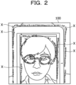
- FIG. 2 is an explanatory diagram illustrating an example of moving straight lines X on a target object image 100.
- the target object image 100 is an image captured by the camera 11 of the evaluation device 1.
- the target object image 100 illustrated in FIG. 2 is, for example, an image including an image of a forgery obtained by an attacker displaying the face image of a legitimate user on the display of a tablet terminal.
- the actual image is, for example, the actual face image of the legitimate user captured by the camera 11.
- the camera shake in the display will produce the moving straight lines X at each position on preceding and succeeding captured images obtained by consecutively capturing.
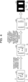
- FIG. 3 is an explanatory diagram illustrating an example of a process of detecting the moving straight lines X on the target object image 100.
- the detection unit 15B quantifies motions at each of a plurality of positions on the consecutive preceding and succeeding target object images 100, using an optical flow that quantifies a motion of an object between adjacent frames produced by the movement of the object or the camera 11, to detect the moving straight lines X at each position.
- the target object images 100 illustrated in FIG. 3 are, for example, three consecutive images obtained by an attacker capturing a forgery with the camera 11.
- the detection unit 15B compares the target object image 100 of I(i-1) with the following target object image 100 of I(i) to detect a moving straight line group including the moving straight lines X at each position. Then, the detection unit 15B detects a target object image 101 of Iv(i-1) including the moving straight line group. In addition, the detection unit 15B compares the target object image 100 of I(i) with the following target object image 100 of I(i+1) to detect a moving straight line group including the moving straight lines X at each position. Then, the detection unit 15B detects a target object image 101 of Iv(i) including the moving straight line group.
- FIG. 4 is an explanatory diagram illustrating an example of a process of specifying the moving straight lines X on the target object image 100.
- the specifying unit 15C specifies moving straight lines X1 greater than the reference value, from among the moving straight lines X at each position on the target object image 101 of Iv(i) detected by the detection unit 15B. Furthermore, the specifying unit 15C specifies moving straight lines X2 in which the difference in the motion direction between the adjacent moving straight lines X1 is less than a predetermined value, for example, moving straight lines X2 in the same direction, from among the specified moving straight lines X1 on a target object image 102 of Iv1(i).
- the specifying unit 15C performs binarization conversion such that the region of the specified moving straight lines X2 on a target object image 103 of Iv2(i) is assigned as "1" and the region other than the region of "1" on the target object image 103 is assigned as "0", to obtain a target object image 104 of Ib(i) after the binarization conversion.
- the regions X3 of "1” are expressed in white, and the region of "0" is expressed in black. Since the camera shake can be seen as a linear action in a unit time, the wider the regions X3 of the moving straight lines X2 in the target object image 104, the more likely the target object image can be determined to be a forgery.
- the evaluation unit 15D calculates the target area of the regions X3 of "1" in the target object image 104 of Ib(i) and compares the target area of the regions X3 of "1" and the total area of the target object image 104 of Ib(i).
- the evaluation unit 15D verifies the target object image 100 to be a forgery when the target area of the regions X3 of "1" is equal to or greater than a threshold value, for example, a predetermined ratio.
- a threshold value for example, a predetermined ratio
- the evaluation unit 15D verifies the target object image 100 to be the real object when the area of the regions X3 of "1" is less than the predetermined ratio.
- the control unit 15E displays a warning on the display unit 12 without executing face authentication with the target object image 100.
- the control unit 15E starts face authentication with the target object image 100.
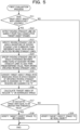
- FIG. 5 is a flowchart illustrating an example of a processing action of the CPU 15 in the evaluation device 1 relating to a first evaluation process.
- the acquisition unit 15A in the CPU 15 determines whether or not the target object images 100 have been consecutively acquired (step S11).
- the detection unit 15B in the CPU 15 detects the moving straight line X on the subject from two consecutive target object images 100 (step S12).
- the specifying unit 15C in the CPU 15 specifies the moving straight line X1 in which the magnitude of the moving straight line X is greater than the reference value, from among the detected moving straight lines X (step S13). Furthermore, the specifying unit 15C specifies the moving straight lines X2 in which the difference between the directions of the adjacent moving straight lines X is less than a predetermined value, from among the specified moving straight lines X1 (step S14).
- the specifying unit 15C converts the target object image 103 into a binarized image in which the region X3 of the moving straight lines X2 specified in step S14 is assigned as “1” and the other regions are assigned as “0” (step S15).
- the specifying unit 15C calculates the target area of the region X3 of "1" in the target object image 104 after the binarization conversion (step S16).
- the evaluation unit 15D in the CPU 15 determines whether or not the target area of the region X3 is equal to or greater than the threshold value (step S17). When the target area is equal to or greater than the threshold value (step S17: Yes), the evaluation unit 15D determines that the target object image 100 is a forgery (step S18) and terminates the processing action illustrated in FIG. 5 .
- step S17: No When the target area is not equal to or greater than the threshold value (step S17: No), the evaluation unit 15D determines that the target object image 100 is the real object (step S19) and terminates the processing action illustrated in FIG. 5 . Then, when the target object image 100 is verified to be the real object, the control unit 15E in the CPU 15 will start biometric authentication using the target object on the target object image 100. When the target object images 100 have not been consecutively acquired (step S11: No), the acquisition unit 15A terminates the processing action illustrated in FIG. 5 .
- the evaluation device 1 detects the moving straight lines X at each position on the subject from the consecutive preceding and succeeding target object images 100 and specifies the moving straight lines X2 of which the magnitude is greater than the reference value and in which the difference between the directions of the adjacent moving straight lines X is less than a predetermined value, from among the detected moving straight lines X.
- the evaluation device 1 binarizes the distribution of the specified moving straight lines X2 and verifies the target object image 100 to be a forgery when the target area of the region X3 of the moving straight lines X2 in the target object image 100 is equal to or greater than the threshold value.
- the evaluation device 1 verifies the target object image 100 to be the real object.
- highly accurate forgery determination is enabled even when the background includes many straight lines.
- the captured target object image 100 may be identified as a forgery.
- the evaluation device 1 does not involve an intentional operation as in performing biometric sensing from the determination result as to whether or not the terminal has been correctly moved in challenge and response as conventionally performed for a legitimate user, the operation burden on the legitimate user may be reduced.
- the evaluation device 1 of the first embodiment binarizes the distribution of the specified moving straight lines X and, when the target area of the region X3 of the moving straight lines X2 in the target object image 100 is equal to or greater than the threshold value, verifies the target object image 100 to be a forgery has been taken as an example.
- the target area of the distribution of the specified moving straight lines X whether or not the target object image 100 is a forgery may be determined, for example, based on the number of specified moving straight lines X in the target object image 100, and an embodiment thereof will be described below as a second embodiment.
- FIG. 6 is an explanatory diagram illustrating an example of the configuration of an evaluation device 1A according to the second embodiment. Note that the same reference signs are given to the same components as those of the evaluation device 1 of the first embodiment, and redundant description of these components and actions will be omitted.
- a CPU 15 in the evaluation device 1A illustrated in FIG. 6 includes a specifying unit 151C and an evaluation unit 151D, as well as an acquisition unit 15A, a detection unit 15B, and a control unit 15E.
- the specifying unit 151C specifies a plurality of moving straight lines X2 in which the magnitude of the detected moving straight line X is greater than a reference value and the difference in a motion direction between the adjacent moving straight lines X is less than a predetermined value.
- the specifying unit 151C estimates the plurality of moving straight lines X2 specified on the target object image 100 as straight lines.
- the specifying unit 151C calculates the number of moving straight lines X4 as a result of straight line estimation on the target object image 100.
- the evaluation unit 151D determines whether or not the number of moving straight lines X4 on the target object image 100 is equal to or greater than a threshold number. The evaluation unit 151D determines that the target object image 100 is a forgery when the number of moving straight lines X4 is equal to or greater than the threshold number. The evaluation unit 151D determines that the target object image 100 is the real object when the number of moving straight lines X4 is less than the threshold number.
- the control unit 15E displays a warning on the display unit 12 without executing face authentication with the target object image 100.
- the control unit 15E starts face authentication with the target object image 100.
- FIG. 7 is an explanatory diagram illustrating an example of a process from detection to specification of the moving straight lines X on the target object image 100.
- the detection unit 15B detects the moving straight lines X at each position from the consecutive preceding and succeeding target object images 100.
- the specifying unit 151C specifies moving straight lines X1 greater than the reference value, from among the moving straight lines X at each position on a target object image 101A of Iv11(i) detected by the detection unit 15B. Furthermore, the specifying unit 151C specifies moving straight lines X2 in which the difference in the motion direction between the adjacent moving straight lines X is less than a predetermined value, from among the specified moving straight lines X1 on a target object image 102A of Iv12(i). The specifying unit 151C estimates a straight line from the moving straight line X2 on the target object image 102A and acquires the number (five) of the moving straight lines X4 estimated as straight lines on a target object image 105.
- the evaluation unit 151D determines whether or not the number of moving straight lines X4 on the target object image 105 is equal to or greater than the threshold value. The evaluation unit 151D determines that the target object image 100 is a forgery when the number of moving straight lines X4 is equal to or greater than the threshold number. The evaluation unit 151D determines that the target object image 100 is the real object when the number of moving straight lines X4 is less than the threshold number.
- FIG. 8 is a flowchart illustrating an example of a processing action of the CPU 15 in the evaluation device 1A relating to a second evaluation process.
- the specifying unit 151C in the CPU 15 executes the process in step S14 to specify the moving straight lines X2 in which the difference between the directions of the adjacent moving straight lines is less than a predetermined value, from among the specified moving straight lines X1.
- the specifying unit 151C estimates the moving straight lines X2 specified in step S14 in the target object image 105 as straight lines (step S21).
- the specifying unit 151C calculates the number of moving straight lines X4 estimated as straight lines in the target object image 105, based on the result of straight line estimation (step S22).
- the evaluation unit 151D determines whether or not the calculated number of moving straight lines X4 is equal to or greater than the threshold number (step S23).
- step S23 When the number of moving straight lines X4 is equal to or greater than the threshold number (step S23: Yes), the evaluation unit 151D determines that the target object image 100 is a forgery (step S24) and terminates the processing action illustrated in FIG. 8 .
- the evaluation unit 151D determines that the target object image 100 is the real object (step S25) and terminates the processing action illustrated in FIG. 8 . Then, when the target object image 100 is verified to be the real object, the control unit 15E will start biometric authentication using the target object on the target object image 100.
- the evaluation device 1A detects the moving straight lines X at each position on the subject from the consecutive preceding and succeeding target object images 100 and specifies the moving straight lines X2 in which the magnitude of the moving straight line is greater than the reference value and the difference between the directions of adjacent moving straight lines is less than a predetermined value, from among the detected moving straight lines X.
- the evaluation device 1A estimates the specified moving straight lines X2 as straight lines and calculates the number of moving straight lines X4 estimated as straight lines.
- the evaluation device 1A verifies the target object image 100 to be a forgery when the number of moving straight lines X4 in the target object image 100 is equal to or greater than the threshold number.
- the evaluation device 1A verifies the target object image 100 to be the real object when the number of moving straight lines X4 in the target object image 100 is less than the threshold number.
- highly accurate forgery determination is enabled even when the background includes many straight lines.
- the captured target object image may be identified as a forgery.
- the evaluation device 1 (1A) detects the moving straight line X from two consecutive preceding and succeeding target object images 100 has been taken as an example.
- the moving straight lines X2 in which the magnitude of the moving straight line is greater than the reference value and the difference between the directions of adjacent moving straight lines is less than a predetermined value may be detected from a pair of preceding and succeeding target object images among three or more target object images, for each pair.
- the target object images may be evaluated for each pair, based on the distribution of the moving straight lines X2 detected for each pair, to aggregate the evaluation results for each pair, and the target object images may be evaluated based on this aggregation result.
- even more highly accurate forgery determination may be implemented.
- the evaluation device 1 (1A) specifies the moving straight lines in which the magnitude of the moving straight line is greater than the reference value and the difference between adjacent moving straight lines is less than a predetermined value and, based on the distribution of the specified moving straight lines, determines whether or not the target object image is a forgery has been taken as an example. However, it may be determined whether or not the target object image is forged, based on the distribution of moving straight lines in which the magnitude of the moving straight line is greater than the reference value.
- the evaluation device 1 (1A) receives the preceding and succeeding target object images captured by an external camera capable of communication connection. Furthermore, the evaluation device 1 (1A) may detect the moving straight line from the received preceding and succeeding target object images and can be changed as appropriate.
- the biometric authentication device may be, for example, a device that executes biometric authentication when logging in to equipment, biometric authentication for a kiosk terminal, biometric authentication when managing entry to and exit from a room, or biometric authentication when using an automated teller machine (ATM) at a bank and can be changed as appropriate.
- ATM automated teller machine
- the evaluation device 1 (1A) may be executed by a cloud, and the moving straight line X may be detected from the preceding and succeeding target object images in the cloud.
- the evaluation device 1 (1A) may detect the moving straight line X from the preceding and succeeding target object images by a server device that manages a plurality of evaluation devices 1 (1A) instead of a computer and can be changed as appropriate.
- the evaluation device 1 (1A) specifies a plurality of moving straight lines X2 in which the magnitude of the detected moving straight line is greater than the reference value and the difference in the motion direction between adjacent moving straight lines is less than a predetermined value has been taken as an example.
- a cloud or a server device may specify a plurality of moving straight lines X2 in which the magnitude of the detected moving straight line is greater than the reference value and the difference in the motion direction between adjacent moving straight lines is less than a predetermined value and can be changed as appropriate.
- the evaluation device 1 determines whether or not the target object image captured by the camera 11 is the real object, based on the target area of the distribution of the specified plurality of moving straight lines X2 has been taken as an example.
- a cloud or a server device may determine whether or not the target object image captured by the camera 11 is the real object, based on the target area of the distribution of the specified plurality of moving straight lines X2 and can be changed as appropriate.
- the evaluation device 1A estimates the plurality of moving straight lines X2 specified on the target object image 100 as straight lines and calculates the number of moving straight lines X4 as a result of straight line estimation on the target object image 100 has been taken as an example.
- a cloud or a server device may estimate the plurality of moving straight lines X2 specified on the target object image 100 as straight lines and calculate the number of moving straight lines X4 as a result of straight line estimation on the target object image 100 and can be changed as appropriate.
- the evaluation device 1A determines whether or not the number of moving straight lines X4 on the target object image 100 is equal to or greater than the threshold number has been taken as an example.
- a cloud or a server device may determine whether or not the number of moving straight lines X4 on the target object image 100 is equal to or greater than the threshold number and can be changed as appropriate.
- each of the constituent elements of each of the units illustrated in the drawings does not necessarily have to be physically configured as illustrated in the drawings. That is, specific forms of separation and integration of each of the units are not limited to the illustrated forms, and all or some of the units may be configured by being functionally or physically separated and integrated in any unit according to various loads, use situations, and the like.
- all or any part of various processing functions performed in each of the devices may be executed by a CPU (or a microcomputer such as a micro processing unit (MPU) and a micro controller unit (MCU)).
- a CPU or a microcomputer such as a micro processing unit (MPU) and a micro controller unit (MCU)
- all or any part of the various processing functions may of course be executed by a program analyzed and executed by a CPU (or a microcomputer such as an MPU and an MCU) or hardware using wired logic.
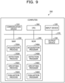
- FIG. 9 is an explanatory diagram illustrating an example of a computer 200 that executes an evaluation program.
- the computer 200 that executes the evaluation program illustrated in FIG. 9 includes a communication device 210, an input device 220, an output device 230, a ROM 240, a RAM 250, a CPU 260, and a bus 270.
- the input device 220 includes a camera or the like that captures the target object.
- the ROM 240 stores in advance an evaluation program that exhibit functions similar to the functions of the above-described embodiments.
- the evaluation program may be recorded on a recording medium readable by a drive (not illustrated) instead of the ROM 240.
- a recording medium may be a portable recording medium such as a compact disc read only memory (CD-ROM), a digital versatile disc (DVD) disk, a universal serial bus (USB) memory, or a secure digital (SD) card, a semiconductor memory such as a flash memory, or the like.
- the evaluation program contains an acquisition program 240A, a detection program 240B, a specifying program 240C, and an evaluation program 240D. Note that the programs 240A, 240B, 240C and 240D may be integrated or separated as appropriate.
- the CPU 260 reads these programs 240A, 240B, 240C, and 240D from the ROM 240 and loads each of these read programs into a work area of the RAM 250. Then, as illustrated in FIG. 9 , the CPU 260 causes each of the programs 240A, 240B, 240C, and 240D loaded into the RAM 250 to function as an acquisition process 250A, a detection process 250B, a specifying process 250C, and an evaluation process 250D.
- the CPU 260 acquires image data including a target object captured by a camera.
- the CPU 260 detects motions at each of a plurality of positions on a subject including the target object captured by the camera, based on the acquired image data.
- the CPU 260 specifies a plurality of the positions where the magnitude of the detected motions is greater than a reference value, from among the plurality of positions on the subject.
- the CPU 260 performs evaluation as to the target object captured by the camera, based on distribution of the specified plurality of the positions on the image data. As a result, highly accurate forgery determination is enabled.
Landscapes
- Engineering & Computer Science (AREA)
- Physics & Mathematics (AREA)
- General Physics & Mathematics (AREA)
- Theoretical Computer Science (AREA)
- Multimedia (AREA)
- Computer Vision & Pattern Recognition (AREA)
- Human Computer Interaction (AREA)
- Health & Medical Sciences (AREA)
- General Health & Medical Sciences (AREA)
- Oral & Maxillofacial Surgery (AREA)
- Image Analysis (AREA)
Abstract
Description
- The present invention relates to an evaluation method, an information processing device, and an evaluation program.
- For example, a system capable of implementing face authentication using an image captured by a commonly spread camera has been widely spread. However, in recent years, face images of other people can be easily obtained, for example, through a social networking service (SNS) or the like. As a result, attacks using forged images are widely known, such as performing face authentication using face images of other people.
- Thus, there is also known a technique for finding a forged image from a moire pattern generated by different reflection characteristics between a forged image of the face image of another person and an actual image.
-
- Patent Document 1:
Japanese Laid-open Patent Publication No. 2006-190259 - Patent Document 2:
Japanese Laid-open Patent Publication No. 2006-133945 - Patent Document 3:
Japanese Laid-open Patent Publication No. 2018-36965 - Non-Patent Document 1: Diago Caetano Garcia et al., "Face-Spoofing 2D-Detection Based on Moire-pattern Analysis", IEEE TRANSACTIONS ON INFORMATION FORENSICS AND SECURITY, VOL. 10, NO. 4, APRIL 2015.
- However, for example, when an image captured with high image quality and presented on a high-brightness and high-resolution display is captured by a general web camera, it is difficult to identify the captured image as a forged image (forgery).
- One aspect is to provide an evaluation method, an information processing device, and an evaluation program that enable highly accurate forgery determination.
- In one mode, as an evaluation method, a computer acquires image data including a target object captured by a camera. The computer detects motions at each of a plurality of positions on a subject including the target object captured by the camera, based on the acquired image data. The computer specifies a plurality of the positions where magnitude of the detected motions is greater than a reference value, from among the plurality of positions on the subject. The computer performs evaluation as to the target object captured by the camera, based on distribution of the specified plurality of the positions on the image data.
- According to an aspect of the embodiments, an evaluation method executed by a computer, the evaluation method includes acquiring image data that includes a target object captured by a camera; detecting motions at each of a plurality of positions on a subject that includes the target object captured by the camera, based on the acquired image data; specifying a plurality of the positions where magnitude of the detected motions is greater than a reference value, from among the plurality of positions on the subject; and performing evaluation as to the target object captured by the camera, based on distribution of the specified plurality of the positions on the image data.
- As one aspect, highly accurate forgery determination is enabled.
-
-
FIG. 1 is an explanatory diagram illustrating an example of the configuration of an evaluation device according to a first embodiment; -
FIG. 2 is an explanatory diagram illustrating an example of moving straight lines on a target object image; -
FIG. 3 is an explanatory diagram illustrating an example of a process of detecting the moving straight lines on the target object image; -
FIG. 4 is an explanatory diagram illustrating an example of a process of specifying the moving straight lines on the target object image; -
FIG. 5 is a flowchart illustrating an example of a processing action of a central processing unit (CPU) in the evaluation device relating to a first evaluation process; -
FIG. 6 is an explanatory diagram illustrating an example of the configuration of an evaluation device according to a second embodiment; -
FIG. 7 is an explanatory diagram illustrating an example of a process from detection to specification of the moving straight lines on the target object image; -
FIG. 8 is a flowchart illustrating an example of a processing action of a CPU in the evaluation device relating to a second evaluation process; and -
FIG. 9 is an explanatory diagram illustrating an example of a computer that executes an evaluation program. - Hereinafter, embodiments of an evaluation device and the like disclosed in the present application will be described in detail with reference to the drawings. Note that the present embodiments do not limit the disclosed technique. In addition, each embodiment described below may be combined as appropriate unless otherwise contradicted.
-
FIG. 1 is an explanatory diagram illustrating an example of the configuration of anevaluation device 1 according to a first embodiment. Theevaluation device 1 illustrated inFIG. 1 is a device that evaluates whether or not a target object image captured when, for example, used for biometric authentication is forged. Theevaluation device 1 includes acamera 11, adisplay unit 12, anoperation unit 13, amemory 14, and a central processing unit (CPU) 15. Thecamera 11 is, for example, an input interface that captures a subject. For example, thecamera 11 is a web camera, an infrared (IR) camera, a depth camera, or the like. Thedisplay unit 12 is an output interface such as a display device that displays various sorts of information. Theoperation unit 13 is, for example, an input interface for inputting commands and the like. Thememory 14 is, for example, a semiconductor memory element such as a read only memory (ROM), a random access memory (RAM), or a flash memory, or a storage device such as a hard disk drive (HDD) or an optical disc that stores various sorts of information. The CPU 15 is an electronic circuit that controls theevaluation device 1 as a whole. - The CPU 15 loads, for example, a program stored in the ROM into the RAM. The CPU 15 functions as, for example, an
acquisition unit 15A, adetection unit 15B, a specifying unit 15C, anevaluation unit 15D, and a control unit 15E by executing a program loaded into the RAM as processes. - The
acquisition unit 15A acquires image data including a target object captured by thecamera 11. Thedetection unit 15B detects motions at each of a plurality of positions on a subject including the target object captured by thecamera 11, based on consecutive preceding and succeeding pieces of the acquired image data. That is, thedetection unit 15B detects moving straight lines, which are motion vectors, as motions at each of a plurality of positions on a target object image of the subject including the target object. Note that, when the target object is assumed as a face image, the target object is, for example, a real face captured by thecamera 11 or a face displayed on another terminal. The subject is all things appearing in the target object image, such as the face image, a background image, a smartphone frame image as examples. - The specifying unit 15C specifies a plurality of positions where the magnitude of the detected motions is greater than a reference value, from among the plurality of positions on the subject. That is, the specifying unit 15C specifies a plurality of moving straight lines in which the magnitude of the detected moving straight lines is greater than the reference value. Furthermore, the specifying unit 15C specifies a plurality of moving straight lines in which the difference in a motion direction between adjacent moving straight lines is less than a predetermined value. The specifying unit 15C calculates the distribution of the specified moving straight lines on the target object image.
- The
evaluation unit 15D performs evaluation as to the target object captured by thecamera 11, based on the distribution of the specified plurality of positions on the image data. That is, theevaluation unit 15D determines whether or not the target object image captured by thecamera 11 is the real object, based on a target area of the distribution of the specified plurality of moving straight lines. Note that the target object is, for example, a biometric target such as a face image, a vein image, or an iris image. The control unit 15E controls the CPU 15 as a whole. The control unit 15E executes biometric authentication such as face authentication, vein authentication, or iris authentication. - When the preceding and succeeding target object images are actual images, the target object images demonstrate natural and complex motions of a person. On the other hand, when the preceding and succeeding target object images are images of a forgery, the target object images will have moving straight lines due to simple linear motions caused by camera shake that occurs when, for example, holding a high-image quality display over the
camera 11. Focusing on this point, whether or not the target object image is a forgery is determined using the distribution of the moving straight lines on the target object image. - The
evaluation device 1 detects the moving straight lines instead of mere straight lines on the target object image. When a mere straight line is detected, a straight line contained in the background of the target object image has influence, and accordingly, when there are many straight lines in the background, there is a possibility that the target object image may be determined to be a forgery. In other words, even if the target object image is not a forgery, the target object image will be determined to be a forgery. Thus, theevaluation device 1 detects the moving straight lines instead of mere straight lines on the target object image to evaluate the target object image based on the distribution of the moving straight lines on the target object image. As a result, even when many straight lines are included in the background, highly accurate forgery determination is enabled. -
FIG. 2 is an explanatory diagram illustrating an example of moving straight lines X on atarget object image 100. Thetarget object image 100 is an image captured by thecamera 11 of theevaluation device 1. Note that thetarget object image 100 illustrated inFIG. 2 is, for example, an image including an image of a forgery obtained by an attacker displaying the face image of a legitimate user on the display of a tablet terminal. The actual image is, for example, the actual face image of the legitimate user captured by thecamera 11. When the image displayed on the display is captured by thecamera 11, the camera shake in the display will produce the moving straight lines X at each position on preceding and succeeding captured images obtained by consecutively capturing. -
FIG. 3 is an explanatory diagram illustrating an example of a process of detecting the moving straight lines X on thetarget object image 100. For example, thedetection unit 15B quantifies motions at each of a plurality of positions on the consecutive preceding and succeedingtarget object images 100, using an optical flow that quantifies a motion of an object between adjacent frames produced by the movement of the object or thecamera 11, to detect the moving straight lines X at each position. - The
target object images 100 illustrated inFIG. 3 are, for example, three consecutive images obtained by an attacker capturing a forgery with thecamera 11. Thedetection unit 15B compares thetarget object image 100 of I(i-1) with the followingtarget object image 100 of I(i) to detect a moving straight line group including the moving straight lines X at each position. Then, thedetection unit 15B detects atarget object image 101 of Iv(i-1) including the moving straight line group. In addition, thedetection unit 15B compares thetarget object image 100 of I(i) with the followingtarget object image 100 of I(i+1) to detect a moving straight line group including the moving straight lines X at each position. Then, thedetection unit 15B detects atarget object image 101 of Iv(i) including the moving straight line group. -
FIG. 4 is an explanatory diagram illustrating an example of a process of specifying the moving straight lines X on thetarget object image 100. The specifying unit 15C specifies moving straight lines X1 greater than the reference value, from among the moving straight lines X at each position on thetarget object image 101 of Iv(i) detected by thedetection unit 15B. Furthermore, the specifying unit 15C specifies moving straight lines X2 in which the difference in the motion direction between the adjacent moving straight lines X1 is less than a predetermined value, for example, moving straight lines X2 in the same direction, from among the specified moving straight lines X1 on a target object image 102 of Iv1(i). Additionally, the specifying unit 15C performs binarization conversion such that the region of the specified moving straight lines X2 on atarget object image 103 of Iv2(i) is assigned as "1" and the region other than the region of "1" on thetarget object image 103 is assigned as "0", to obtain a target object image 104 of Ib(i) after the binarization conversion. Note that, in the target object image 104 of Ib(i) illustrated inFIG. 4 , the regions X3 of "1" are expressed in white, and the region of "0" is expressed in black. Since the camera shake can be seen as a linear action in a unit time, the wider the regions X3 of the moving straight lines X2 in the target object image 104, the more likely the target object image can be determined to be a forgery. - Then, the
evaluation unit 15D calculates the target area of the regions X3 of "1" in the target object image 104 of Ib(i) and compares the target area of the regions X3 of "1" and the total area of the target object image 104 of Ib(i). Theevaluation unit 15D verifies thetarget object image 100 to be a forgery when the target area of the regions X3 of "1" is equal to or greater than a threshold value, for example, a predetermined ratio. In addition, theevaluation unit 15D verifies thetarget object image 100 to be the real object when the area of the regions X3 of "1" is less than the predetermined ratio. - When it is verified that the
target object image 100 is a forgery, the control unit 15E displays a warning on thedisplay unit 12 without executing face authentication with thetarget object image 100. When it is verified that thetarget object image 100 is the real object, the control unit 15E starts face authentication with thetarget object image 100. -
FIG. 5 is a flowchart illustrating an example of a processing action of the CPU 15 in theevaluation device 1 relating to a first evaluation process. InFIG. 5 , theacquisition unit 15A in the CPU 15 determines whether or not thetarget object images 100 have been consecutively acquired (step S11). When thetarget object images 100 have been consecutively acquired (step S11: Yes), thedetection unit 15B in the CPU 15 detects the moving straight line X on the subject from two consecutive target object images 100 (step S12). - The specifying unit 15C in the CPU 15 specifies the moving straight line X1 in which the magnitude of the moving straight line X is greater than the reference value, from among the detected moving straight lines X (step S13). Furthermore, the specifying unit 15C specifies the moving straight lines X2 in which the difference between the directions of the adjacent moving straight lines X is less than a predetermined value, from among the specified moving straight lines X1 (step S14).
- Then, the specifying unit 15C converts the
target object image 103 into a binarized image in which the region X3 of the moving straight lines X2 specified in step S14 is assigned as "1" and the other regions are assigned as "0" (step S15). The specifying unit 15C calculates the target area of the region X3 of "1" in the target object image 104 after the binarization conversion (step S16). - The
evaluation unit 15D in the CPU 15 determines whether or not the target area of the region X3 is equal to or greater than the threshold value (step S17). When the target area is equal to or greater than the threshold value (step S17: Yes), theevaluation unit 15D determines that thetarget object image 100 is a forgery (step S18) and terminates the processing action illustrated inFIG. 5 . - When the target area is not equal to or greater than the threshold value (step S17: No), the
evaluation unit 15D determines that thetarget object image 100 is the real object (step S19) and terminates the processing action illustrated inFIG. 5 . Then, when thetarget object image 100 is verified to be the real object, the control unit 15E in the CPU 15 will start biometric authentication using the target object on thetarget object image 100. When thetarget object images 100 have not been consecutively acquired (step S11: No), theacquisition unit 15A terminates the processing action illustrated inFIG. 5 . - The
evaluation device 1 detects the moving straight lines X at each position on the subject from the consecutive preceding and succeedingtarget object images 100 and specifies the moving straight lines X2 of which the magnitude is greater than the reference value and in which the difference between the directions of the adjacent moving straight lines X is less than a predetermined value, from among the detected moving straight lines X. Theevaluation device 1 binarizes the distribution of the specified moving straight lines X2 and verifies thetarget object image 100 to be a forgery when the target area of the region X3 of the moving straight lines X2 in thetarget object image 100 is equal to or greater than the threshold value. Furthermore, when the target area of the region X3 of the moving straight lines X2 in thetarget object image 100 is less than the threshold value, theevaluation device 1 verifies thetarget object image 100 to be the real object. As a result, highly accurate forgery determination is enabled even when the background includes many straight lines. In addition, for example, when an image captured with high image quality and presented on a high-brightness and high-resolution display is captured by thecamera 11, the capturedtarget object image 100 may be identified as a forgery. - Since the
evaluation device 1 does not involve an intentional operation as in performing biometric sensing from the determination result as to whether or not the terminal has been correctly moved in challenge and response as conventionally performed for a legitimate user, the operation burden on the legitimate user may be reduced. - Note that the case where the
evaluation device 1 of the first embodiment binarizes the distribution of the specified moving straight lines X and, when the target area of the region X3 of the moving straight lines X2 in thetarget object image 100 is equal to or greater than the threshold value, verifies thetarget object image 100 to be a forgery has been taken as an example. However, besides the target area of the distribution of the specified moving straight lines X, whether or not thetarget object image 100 is a forgery may be determined, for example, based on the number of specified moving straight lines X in thetarget object image 100, and an embodiment thereof will be described below as a second embodiment. -
FIG. 6 is an explanatory diagram illustrating an example of the configuration of anevaluation device 1A according to the second embodiment. Note that the same reference signs are given to the same components as those of theevaluation device 1 of the first embodiment, and redundant description of these components and actions will be omitted. - A CPU 15 in the
evaluation device 1A illustrated inFIG. 6 includes a specifyingunit 151C and anevaluation unit 151D, as well as anacquisition unit 15A, adetection unit 15B, and a control unit 15E. The specifyingunit 151C specifies a plurality of moving straight lines X2 in which the magnitude of the detected moving straight line X is greater than a reference value and the difference in a motion direction between the adjacent moving straight lines X is less than a predetermined value. The specifyingunit 151C estimates the plurality of moving straight lines X2 specified on thetarget object image 100 as straight lines. The specifyingunit 151C calculates the number of moving straight lines X4 as a result of straight line estimation on thetarget object image 100. - The
evaluation unit 151D determines whether or not the number of moving straight lines X4 on thetarget object image 100 is equal to or greater than a threshold number. Theevaluation unit 151D determines that thetarget object image 100 is a forgery when the number of moving straight lines X4 is equal to or greater than the threshold number. Theevaluation unit 151D determines that thetarget object image 100 is the real object when the number of moving straight lines X4 is less than the threshold number. - When it is verified that the
target object image 100 is a forgery, the control unit 15E displays a warning on thedisplay unit 12 without executing face authentication with thetarget object image 100. When it is verified that thetarget object image 100 is the real object, the control unit 15E starts face authentication with thetarget object image 100. -
FIG. 7 is an explanatory diagram illustrating an example of a process from detection to specification of the moving straight lines X on thetarget object image 100. Thedetection unit 15B detects the moving straight lines X at each position from the consecutive preceding and succeedingtarget object images 100. The specifyingunit 151C specifies moving straight lines X1 greater than the reference value, from among the moving straight lines X at each position on atarget object image 101A of Iv11(i) detected by thedetection unit 15B. Furthermore, the specifyingunit 151C specifies moving straight lines X2 in which the difference in the motion direction between the adjacent moving straight lines X is less than a predetermined value, from among the specified moving straight lines X1 on atarget object image 102A of Iv12(i). The specifyingunit 151C estimates a straight line from the moving straight line X2 on thetarget object image 102A and acquires the number (five) of the moving straight lines X4 estimated as straight lines on atarget object image 105. - The
evaluation unit 151D determines whether or not the number of moving straight lines X4 on thetarget object image 105 is equal to or greater than the threshold value. Theevaluation unit 151D determines that thetarget object image 100 is a forgery when the number of moving straight lines X4 is equal to or greater than the threshold number. Theevaluation unit 151D determines that thetarget object image 100 is the real object when the number of moving straight lines X4 is less than the threshold number. -
FIG. 8 is a flowchart illustrating an example of a processing action of the CPU 15 in theevaluation device 1A relating to a second evaluation process. InFIG. 8 , the specifyingunit 151C in the CPU 15 executes the process in step S14 to specify the moving straight lines X2 in which the difference between the directions of the adjacent moving straight lines is less than a predetermined value, from among the specified moving straight lines X1. The specifyingunit 151C estimates the moving straight lines X2 specified in step S14 in thetarget object image 105 as straight lines (step S21). - The specifying
unit 151C calculates the number of moving straight lines X4 estimated as straight lines in thetarget object image 105, based on the result of straight line estimation (step S22). Theevaluation unit 151D determines whether or not the calculated number of moving straight lines X4 is equal to or greater than the threshold number (step S23). - When the number of moving straight lines X4 is equal to or greater than the threshold number (step S23: Yes), the
evaluation unit 151D determines that thetarget object image 100 is a forgery (step S24) and terminates the processing action illustrated inFIG. 8 . - When the number of moving straight lines X4 is not equal to or greater than the threshold number (step S23: No), the
evaluation unit 151D determines that thetarget object image 100 is the real object (step S25) and terminates the processing action illustrated inFIG. 8 . Then, when thetarget object image 100 is verified to be the real object, the control unit 15E will start biometric authentication using the target object on thetarget object image 100. - The
evaluation device 1A detects the moving straight lines X at each position on the subject from the consecutive preceding and succeedingtarget object images 100 and specifies the moving straight lines X2 in which the magnitude of the moving straight line is greater than the reference value and the difference between the directions of adjacent moving straight lines is less than a predetermined value, from among the detected moving straight lines X. Theevaluation device 1A estimates the specified moving straight lines X2 as straight lines and calculates the number of moving straight lines X4 estimated as straight lines. Theevaluation device 1A verifies thetarget object image 100 to be a forgery when the number of moving straight lines X4 in thetarget object image 100 is equal to or greater than the threshold number. Furthermore, theevaluation device 1A verifies thetarget object image 100 to be the real object when the number of moving straight lines X4 in thetarget object image 100 is less than the threshold number. As a result, highly accurate forgery determination is enabled even when the background includes many straight lines. In addition, for example, when an image captured with high image quality and presented on a high-brightness and high-resolution display is captured by thecamera 11, the captured target object image may be identified as a forgery. - Note that, for convenience of explanation, the case where the evaluation device 1 (1A) detects the moving straight line X from two consecutive preceding and succeeding
target object images 100 has been taken as an example. However, besides two target object images, the moving straight lines X2 in which the magnitude of the moving straight line is greater than the reference value and the difference between the directions of adjacent moving straight lines is less than a predetermined value may be detected from a pair of preceding and succeeding target object images among three or more target object images, for each pair. The target object images may be evaluated for each pair, based on the distribution of the moving straight lines X2 detected for each pair, to aggregate the evaluation results for each pair, and the target object images may be evaluated based on this aggregation result. As a result, even more highly accurate forgery determination may be implemented. - The case where the evaluation device 1 (1A) specifies the moving straight lines in which the magnitude of the moving straight line is greater than the reference value and the difference between adjacent moving straight lines is less than a predetermined value and, based on the distribution of the specified moving straight lines, determines whether or not the target object image is a forgery has been taken as an example. However, it may be determined whether or not the target object image is forged, based on the distribution of moving straight lines in which the magnitude of the moving straight line is greater than the reference value.
- The case of detecting the moving straight line from the preceding and succeeding target object images captured by the built-in
camera 11 has been taken as an example, but the evaluation device 1 (1A) receives the preceding and succeeding target object images captured by an external camera capable of communication connection. Furthermore, the evaluation device 1 (1A) may detect the moving straight line from the received preceding and succeeding target object images and can be changed as appropriate. - In addition, the case where the evaluation device 1 (1A) is applied to a biometric authentication device that executes biometric authentication using the target object on the target object image when the target object image is the real object has been taken as an example. The biometric authentication device may be, for example, a device that executes biometric authentication when logging in to equipment, biometric authentication for a kiosk terminal, biometric authentication when managing entry to and exit from a room, or biometric authentication when using an automated teller machine (ATM) at a bank and can be changed as appropriate.
- Although the case where the evaluation device 1 (1A) is executed by a computer has been taken as an example, the evaluation device 1 (1A) may be executed by a cloud, and the moving straight line X may be detected from the preceding and succeeding target object images in the cloud. In addition, the evaluation device 1 (1A) may detect the moving straight line X from the preceding and succeeding target object images by a server device that manages a plurality of evaluation devices 1 (1A) instead of a computer and can be changed as appropriate.
- In addition, the case where the evaluation device 1 (1A) specifies a plurality of moving straight lines X2 in which the magnitude of the detected moving straight line is greater than the reference value and the difference in the motion direction between adjacent moving straight lines is less than a predetermined value has been taken as an example. However, a cloud or a server device may specify a plurality of moving straight lines X2 in which the magnitude of the detected moving straight line is greater than the reference value and the difference in the motion direction between adjacent moving straight lines is less than a predetermined value and can be changed as appropriate.
- The case where the
evaluation device 1 determines whether or not the target object image captured by thecamera 11 is the real object, based on the target area of the distribution of the specified plurality of moving straight lines X2 has been taken as an example. However, a cloud or a server device may determine whether or not the target object image captured by thecamera 11 is the real object, based on the target area of the distribution of the specified plurality of moving straight lines X2 and can be changed as appropriate. - The case where the
evaluation device 1A estimates the plurality of moving straight lines X2 specified on thetarget object image 100 as straight lines and calculates the number of moving straight lines X4 as a result of straight line estimation on thetarget object image 100 has been taken as an example. However, a cloud or a server device may estimate the plurality of moving straight lines X2 specified on thetarget object image 100 as straight lines and calculate the number of moving straight lines X4 as a result of straight line estimation on thetarget object image 100 and can be changed as appropriate. - The case where the
evaluation device 1A determines whether or not the number of moving straight lines X4 on thetarget object image 100 is equal to or greater than the threshold number has been taken as an example. However, a cloud or a server device may determine whether or not the number of moving straight lines X4 on thetarget object image 100 is equal to or greater than the threshold number and can be changed as appropriate. - In addition, each of the constituent elements of each of the units illustrated in the drawings does not necessarily have to be physically configured as illustrated in the drawings. That is, specific forms of separation and integration of each of the units are not limited to the illustrated forms, and all or some of the units may be configured by being functionally or physically separated and integrated in any unit according to various loads, use situations, and the like.
- Furthermore, all or any part of various processing functions performed in each of the devices may be executed by a CPU (or a microcomputer such as a micro processing unit (MPU) and a micro controller unit (MCU)). In addition, all or any part of the various processing functions may of course be executed by a program analyzed and executed by a CPU (or a microcomputer such as an MPU and an MCU) or hardware using wired logic.
- Incidentally, the various processes described in the present embodiments can be implemented by an information processing device such as a computer executing a program prepared in advance. Thus, in the following, an example of a computer that executes a program having functions similar to the functions of the above embodiments will be described.
FIG. 9 is an explanatory diagram illustrating an example of acomputer 200 that executes an evaluation program. - The
computer 200 that executes the evaluation program illustrated inFIG. 9 includes acommunication device 210, aninput device 220, anoutput device 230, aROM 240, aRAM 250, aCPU 260, and abus 270. Note that theinput device 220 includes a camera or the like that captures the target object. - Then, the
ROM 240 stores in advance an evaluation program that exhibit functions similar to the functions of the above-described embodiments. Note that the evaluation program may be recorded on a recording medium readable by a drive (not illustrated) instead of theROM 240. In addition, for example, a recording medium may be a portable recording medium such as a compact disc read only memory (CD-ROM), a digital versatile disc (DVD) disk, a universal serial bus (USB) memory, or a secure digital (SD) card, a semiconductor memory such as a flash memory, or the like. As illustrated inFIG. 9 , the evaluation program contains anacquisition program 240A, adetection program 240B, a specifyingprogram 240C, and anevaluation program 240D. Note that theprograms - Then, the
CPU 260 reads theseprograms ROM 240 and loads each of these read programs into a work area of theRAM 250. Then, as illustrated inFIG. 9 , theCPU 260 causes each of theprograms RAM 250 to function as anacquisition process 250A, adetection process 250B, a specifyingprocess 250C, and anevaluation process 250D. - The
CPU 260 acquires image data including a target object captured by a camera. TheCPU 260 detects motions at each of a plurality of positions on a subject including the target object captured by the camera, based on the acquired image data. TheCPU 260 specifies a plurality of the positions where the magnitude of the detected motions is greater than a reference value, from among the plurality of positions on the subject. TheCPU 260 performs evaluation as to the target object captured by the camera, based on distribution of the specified plurality of the positions on the image data. As a result, highly accurate forgery determination is enabled. -
- 1
- evaluation device
- 15A
- acquisition unit
- 15B
- detection unit
- 15C
- specifying unit
- 15D
- evaluation unit
- 151C
- specifying unit
- 151D
- evaluation unit
Claims (20)
- An evaluation method executed by a computer, the evaluation method comprising:acquiring image data that includes a target object captured by a camera;detecting motions at each of a plurality of positions on a subject that includes the target object captured by the camera, based on the acquired image data;specifying a plurality of the positions where magnitude of the detected motions is greater than a reference value, from among the plurality of positions on the subject; andperforming evaluation as to the target object captured by the camera, based on distribution of the specified plurality of the positions on the image data.
- The evaluation method according to claim 1, whereinthe detecting includes detecting moving straight lines as the motions at each of the plurality of positions on the subject that includes the target object,the specifying includes specifying a plurality of the moving straight lines in which the magnitude of the detected moving straight lines is greater than the reference value, andthe performing includes performing the evaluation as to the target object captured by the camera, based on the distribution of the specified plurality of the moving straight lines on the image data.
- The evaluation method according to claim 2, wherein the specifying includes specifying the plurality of the moving straight lines in which the magnitude of the detected moving straight lines is greater than the reference value and a difference in a motion direction between adjacent moving straight lines is less than a predetermined value.
- The evaluation method according to claim 2 or 3, wherein the performing includes performing the evaluation as to the target object captured by the camera, based on the distribution of the specified plurality of the moving straight lines.
- The evaluation method according to claim 2 or 3, wherein the performing includes performing the evaluation as to the target object captured by the camera, based on a number of the specified plurality of the moving straight lines.
- The evaluation method according to any one of claims 1 to 3, wherein the detecting includes detecting the motions at each of the plurality of positions on the subject that includes the target object captured by the camera, based on consecutive preceding and succeeding pieces of the acquired image data.
- The evaluation method according to any one of claims 1 to 3, wherein the performing includes performing the evaluation as to whether or not the target object is a real object.
- An information processing device comprising:an acquisition unit that acquires image data that includes a target object captured by a camera;a detection unit that detects motions at each of a plurality of positions on a subject that includes the target object captured by the camera, based on the acquired image data;a specifying unit that specifies a plurality of the positions where magnitude of the detected motions is greater than a reference value, from among the plurality of positions on the subject; andan evaluation unit that performs evaluation as to the target object captured by the camera, based on distribution of the specified plurality of the positions on the image data.
- The information processing device according to claim 8, whereinthe detection unit detects moving straight lines as the motions at each of the plurality of positions on the subject that includes the target object,the specifying unit specifies a plurality of the moving straight lines in which the magnitude of the detected moving straight lines is greater than the reference value, andthe evaluation unit performs the evaluation as to the target object captured by the camera, based on the distribution of the specified plurality of the moving straight lines on the image data.
- The information processing device according to claim 9, wherein the specifying unit specifies the plurality of the moving straight lines in which the magnitude of the detected moving straight lines is greater than the reference value and a difference in a motion direction between adjacent moving straight lines is less than a predetermined value.
- The information processing device according to claim 9 or 10,
wherein the evaluation unit performs the evaluation as to the target object captured by the camera, based on the distribution of the specified plurality of the moving straight lines. - The information processing device according to claim 9 or 10, wherein the evaluation unit performs the evaluation as to the target object captured by the camera, based on a number of the specified plurality of the moving straight lines.
- The information processing device according to any one of claims 8 to 10, wherein the detection unit detects the motions at each of the plurality of positions on the subject that includes the target object captured by the camera, based on consecutive preceding and succeeding pieces of the acquired image data.
- The information processing device according to any one of claims 8 to 10, wherein the evaluation unit performs the evaluation as to whether or not the target object is a real object.
- An evaluation program that causes a computer to execute a process, the process comprising:acquiring image data that includes a target object captured by a camera;detecting motions at each of a plurality of positions on a subject that includes the target object captured by the camera, based on the acquired image data;specifying a plurality of the positions where magnitude of the detected motions is greater than a reference value, from among the plurality of positions on the subject; andperforming evaluation as to the target object captured by the camera, based on distribution of the specified plurality of the positions on the image data.
- The evaluation program according to claim 15, whereinthe detecting includes detecting moving straight lines as the motions at each of the plurality of positions on the subject that includes the target object,the specifying includes specifying a plurality of the moving straight lines in which the magnitude of the detected moving straight lines is greater than the reference value, andthe performing includes performing the evaluation as to the target object captured by the camera, based on the distribution of the specified plurality of the moving straight lines on the image data.
- The evaluation program according to claim 16, wherein the specifying includes specifying the plurality of the moving straight lines in which the magnitude of the detected moving straight lines is greater than the reference value and a difference in a motion direction between adjacent moving straight lines is less than a predetermined value.
- The evaluation program according to claim 16 or 17, wherein the performing includes performing the evaluation as to the target object captured by the camera, based on the distribution of the specified plurality of the moving straight lines.
- The evaluation program according to claim 16 or 17, wherein the performing includes performing the evaluation as to the target object captured by the camera, based on a number of the specified plurality of the moving straight lines.
- The evaluation program according to any one of claims 15 to 17, wherein the detecting includes detecting the motions at each of the plurality of positions on the subject that includes the target object captured by the camera, based on consecutive preceding and succeeding pieces of the acquired image data.
Applications Claiming Priority (1)
| Application Number | Priority Date | Filing Date | Title |
|---|---|---|---|
| PCT/JP2020/028901 WO2022024222A1 (en) | 2020-07-28 | 2020-07-28 | Evaluation method, information processing device, and evaluation program |
Publications (2)
| Publication Number | Publication Date |
|---|---|
| EP4191519A1 true EP4191519A1 (en) | 2023-06-07 |
| EP4191519A4 EP4191519A4 (en) | 2023-08-16 |
Family
ID=80037845
Family Applications (1)
| Application Number | Title | Priority Date | Filing Date |
|---|---|---|---|
| EP20946647.3A Withdrawn EP4191519A4 (en) | 2020-07-28 | 2020-07-28 | EVALUATION METHOD, INFORMATION PROCESSING DEVICE AND EVALUATION PROGRAM |
Country Status (5)
| Country | Link |
|---|---|
| US (1) | US20230091526A1 (en) |
| EP (1) | EP4191519A4 (en) |
| JP (1) | JPWO2022024222A1 (en) |
| CN (1) | CN115701307A (en) |
| WO (1) | WO2022024222A1 (en) |
Family Cites Families (6)
| Publication number | Priority date | Publication date | Assignee | Title |
|---|---|---|---|---|
| JP2006133945A (en) | 2004-11-04 | 2006-05-25 | Matsushita Electric Ind Co Ltd | Verification device, verification method and verification program |
| JP2006190259A (en) | 2004-12-06 | 2006-07-20 | Canon Inc | Camera shake determination apparatus, image processing apparatus, control method thereof, and program |
| JP5087037B2 (en) * | 2009-03-25 | 2012-11-28 | 株式会社東芝 | Image processing apparatus, method, and program |
| JP6754642B2 (en) | 2016-09-01 | 2020-09-16 | 株式会社日立製作所 | Biodetector |
| US10515199B2 (en) * | 2017-04-19 | 2019-12-24 | Qualcomm Incorporated | Systems and methods for facial authentication |
| CN108388881A (en) * | 2018-03-15 | 2018-08-10 | 广东工业大学 | A kind of method for anti-counterfeit and device for distinguishing true man and photo playback |
-
2020
- 2020-07-28 CN CN202080102154.5A patent/CN115701307A/en active Pending
- 2020-07-28 WO PCT/JP2020/028901 patent/WO2022024222A1/en not_active Ceased
- 2020-07-28 JP JP2022539837A patent/JPWO2022024222A1/ja not_active Withdrawn
- 2020-07-28 EP EP20946647.3A patent/EP4191519A4/en not_active Withdrawn
-
2022
- 2022-11-30 US US18/060,247 patent/US20230091526A1/en not_active Abandoned
Also Published As
| Publication number | Publication date |
|---|---|
| JPWO2022024222A1 (en) | 2022-02-03 |
| EP4191519A4 (en) | 2023-08-16 |
| CN115701307A (en) | 2023-02-07 |
| WO2022024222A1 (en) | 2022-02-03 |
| US20230091526A1 (en) | 2023-03-23 |
Similar Documents
| Publication | Publication Date | Title |
|---|---|---|
| JP5831193B2 (en) | User detection device, method and program | |
| EP2866170B1 (en) | Image processing device and image processing method | |
| US8660317B2 (en) | Object image detection method and object image detection device for detecting an object image from an input image | |
| US20210303829A1 (en) | Face liveness detection using background/foreground motion analysis | |
| US8582833B2 (en) | Method and apparatus for detecting forged face using infrared image | |
| TWI686774B (en) | Human face live detection method and device | |
| US20190034746A1 (en) | System and method for identifying re-photographed images | |
| CN107111744B (en) | Detect impersonation attacks against video-based authentication | |
| US20150146006A1 (en) | Display control apparatus and display control method | |
| EP2919153A1 (en) | Event detection apparatus and event detection method | |
| JP2009211311A (en) | Image processing apparatus and method | |
| JP6532190B2 (en) | Image search apparatus, image search method | |
| KR100824757B1 (en) | Biometric method using gait | |
| JP5649601B2 (en) | Verification device, method and program | |
| CN111144293A (en) | Human face identity authentication system with interactive living body detection and method thereof | |
| US11210528B2 (en) | Information processing apparatus, information processing method, system, and storage medium to determine staying time of a person in predetermined region | |
| US10691956B2 (en) | Information processing apparatus, information processing system, information processing method, and storage medium having determination areas corresponding to waiting line | |
| JP6289308B2 (en) | Information processing apparatus and program | |
| CN107958202B (en) | Human body detection apparatus, control method of human body detection apparatus, and storage medium | |
| JP2012068948A (en) | Face attribute estimating apparatus and method therefor | |
| KR20160068281A (en) | Method of object recognition | |
| JP2007233871A (en) | Image processor, control method for computer, and program | |
| EP4191519A1 (en) | Evaluation method, information processing device, and evaluation program | |
| JP2012100082A (en) | Image processing device, image processing method, and program | |
| CN114092986B (en) | Living face detection method and device |
Legal Events
| Date | Code | Title | Description |
|---|---|---|---|
| STAA | Information on the status of an ep patent application or granted ep patent |
Free format text: STATUS: THE INTERNATIONAL PUBLICATION HAS BEEN MADE |
|
| PUAI | Public reference made under article 153(3) epc to a published international application that has entered the european phase |
Free format text: ORIGINAL CODE: 0009012 |
|
| STAA | Information on the status of an ep patent application or granted ep patent |
Free format text: STATUS: REQUEST FOR EXAMINATION WAS MADE |
|
| 17P | Request for examination filed |
Effective date: 20221201 |
|
| AK | Designated contracting states |
Kind code of ref document: A1 Designated state(s): AL AT BE BG CH CY CZ DE DK EE ES FI FR GB GR HR HU IE IS IT LI LT LU LV MC MK MT NL NO PL PT RO RS SE SI SK SM TR |
|
| REG | Reference to a national code |
Ref country code: DE Ref legal event code: R079 Free format text: PREVIOUS MAIN CLASS: G06T0007000000 Ipc: G06V0040400000 |
|
| A4 | Supplementary search report drawn up and despatched |
Effective date: 20230714 |
|
| RIC1 | Information provided on ipc code assigned before grant |
Ipc: G06V 10/44 20220101ALI20230710BHEP Ipc: G06V 40/16 20220101ALI20230710BHEP Ipc: G06V 40/40 20220101AFI20230710BHEP |
|
| STAA | Information on the status of an ep patent application or granted ep patent |
Free format text: STATUS: THE APPLICATION HAS BEEN WITHDRAWN |
|
| DAV | Request for validation of the european patent (deleted) | ||
| DAX | Request for extension of the european patent (deleted) | ||
| 18W | Application withdrawn |
Effective date: 20231024 |