EP4191378A2 - Electronic device, expansion structure for electronic card and assembly method thereof - Google Patents
Electronic device, expansion structure for electronic card and assembly method thereof Download PDFInfo
- Publication number
- EP4191378A2 EP4191378A2 EP22210865.6A EP22210865A EP4191378A2 EP 4191378 A2 EP4191378 A2 EP 4191378A2 EP 22210865 A EP22210865 A EP 22210865A EP 4191378 A2 EP4191378 A2 EP 4191378A2
- Authority
- EP
- European Patent Office
- Prior art keywords
- electronic card
- carrier board
- expansion structure
- sidewall
- fixing element
- Prior art date
- Legal status (The legal status is an assumption and is not a legal conclusion. Google has not performed a legal analysis and makes no representation as to the accuracy of the status listed.)
- Pending
Links
Images



Classifications
-
- H—ELECTRICITY
- H01—ELECTRIC ELEMENTS
- H01R—ELECTRICALLY-CONDUCTIVE CONNECTIONS; STRUCTURAL ASSOCIATIONS OF A PLURALITY OF MUTUALLY-INSULATED ELECTRICAL CONNECTING ELEMENTS; COUPLING DEVICES; CURRENT COLLECTORS
- H01R12/00—Structural associations of a plurality of mutually-insulated electrical connecting elements, specially adapted for printed circuits, e.g. printed circuit boards [PCB], flat or ribbon cables, or like generally planar structures, e.g. terminal strips, terminal blocks; Coupling devices specially adapted for printed circuits, flat or ribbon cables, or like generally planar structures; Terminals specially adapted for contact with, or insertion into, printed circuits, flat or ribbon cables, or like generally planar structures
- H01R12/70—Coupling devices
- H01R12/7005—Guiding, mounting, polarizing or locking means; Extractors
- H01R12/7011—Locking or fixing a connector to a PCB
- H01R12/7052—Locking or fixing a connector to a PCB characterised by the locating members
-
- G—PHYSICS
- G06—COMPUTING OR CALCULATING; COUNTING
- G06F—ELECTRIC DIGITAL DATA PROCESSING
- G06F1/00—Details not covered by groups G06F3/00 - G06F13/00 and G06F21/00
- G06F1/16—Constructional details or arrangements
- G06F1/18—Packaging or power distribution
- G06F1/183—Internal mounting support structures, e.g. for supporting printed circuit boards
- G06F1/185—Mounting of expansion boards
-
- H—ELECTRICITY
- H01—ELECTRIC ELEMENTS
- H01R—ELECTRICALLY-CONDUCTIVE CONNECTIONS; STRUCTURAL ASSOCIATIONS OF A PLURALITY OF MUTUALLY-INSULATED ELECTRICAL CONNECTING ELEMENTS; COUPLING DEVICES; CURRENT COLLECTORS
- H01R12/00—Structural associations of a plurality of mutually-insulated electrical connecting elements, specially adapted for printed circuits, e.g. printed circuit boards [PCB], flat or ribbon cables, or like generally planar structures, e.g. terminal strips, terminal blocks; Coupling devices specially adapted for printed circuits, flat or ribbon cables, or like generally planar structures; Terminals specially adapted for contact with, or insertion into, printed circuits, flat or ribbon cables, or like generally planar structures
- H01R12/70—Coupling devices
- H01R12/71—Coupling devices for rigid printing circuits or like structures
-
- H—ELECTRICITY
- H01—ELECTRIC ELEMENTS
- H01R—ELECTRICALLY-CONDUCTIVE CONNECTIONS; STRUCTURAL ASSOCIATIONS OF A PLURALITY OF MUTUALLY-INSULATED ELECTRICAL CONNECTING ELEMENTS; COUPLING DEVICES; CURRENT COLLECTORS
- H01R43/00—Apparatus or processes specially adapted for manufacturing, assembling, maintaining, or repairing of line connectors or current collectors or for joining electric conductors
-
- H—ELECTRICITY
- H01—ELECTRIC ELEMENTS
- H01R—ELECTRICALLY-CONDUCTIVE CONNECTIONS; STRUCTURAL ASSOCIATIONS OF A PLURALITY OF MUTUALLY-INSULATED ELECTRICAL CONNECTING ELEMENTS; COUPLING DEVICES; CURRENT COLLECTORS
- H01R43/00—Apparatus or processes specially adapted for manufacturing, assembling, maintaining, or repairing of line connectors or current collectors or for joining electric conductors
- H01R43/26—Apparatus or processes specially adapted for manufacturing, assembling, maintaining, or repairing of line connectors or current collectors or for joining electric conductors for engaging or disengaging the two parts of a coupling device
Definitions
- the present invention relates to an expansion structure, and more particularly to an expansion structure for an electronic card.
- the 4G mobile communication technology allow electronic devices such as smart phones, tablet computers or laptop computers to be equipped with 4G electronic cards (for example, SIM cards) to thereby run online games or view streaming videos.
- 4G electronic cards for example, SIM cards
- 5G mobile communication technology mobile communication network, wireless network and wired network technologies are combined, such that innovations of large networks are further stimulated while transmission speeds are significantly increased, providing a vast application field.
- the present invention provides an expansion structure for an electronic card for installing an electronic card.
- the expansion structure includes a carrier board, at least on limiting member and a fixing element.
- the carrier board carries the electronic card.
- the limiting member includes a sidewall and a blocking piece extended from the sidewall.
- the sidewall is formed on one side of the carrier board, and the sidewall, the blocking piece and the carrier board jointly define a sliding channel for accommodating the electronic card.
- the fixing element fixes the electronic card at the carrier board.
- the present invention further provides an electronic device for installing an electronic card, wherein the electronic card has an insertion end.
- the electronic device includes a circuit board and an expansion structure.
- the circuit board is provided with a connector slot.
- the expansion structure includes a carrier board and a fixing element.
- the electronic card is fastened at the carrier board and is fixed by the fixing element.
- a sidewall is formed on one side of the carrier board, and a blocking piece extends inward from the sidewall such that the blocking piece and the sidewall jointly cover the side of the electronic card.
- the expansion structure is disposed at the circuit board, and is for connecting the insertion end and the connector slot with each other.
- the present invention further provides an assembly method for assembling an external electronic component to an electronic device.
- the assembly method includes: providing an electronic device, a carrier board, a fixing element and an electronic card, wherein the electronic device is provided with a circuit board, the circuit board is provided with a connector slot, a sidewall is formed on a side of the carrier board, a blocking piece is extended form the sidewall, the carrier board, the sidewall and the blocking piece jointly define a sliding channel, and the electronic card has an insertion end; inserting one end of the electronic card away from the insertion end into the sliding channel to install the electronic card at the carrier board; fixing the electronic card on the carrier board by the fixing element to form an expansion structure; and connecting the insertion end and the connector slot with each other, and fixing the expansion structure on the circuit board.
- the present invention at least provides the following effects.
- the electronic card By carrying at least one-third of the area of a bottom surface of the electronic card by the carrier board, the electronic card can be effectively supported by the carrier board.
- the fixing element is capable of fixing the electronic card on the carrier board.
- the expansion structure can be fixed on the circuit board by a tightening component and a connecting column.
- the present invention provides an expansions structure for an electronic card for installing an electronic card A.
- the expansion structure primarily includes a carrier board 10, at least one limiting member 20 and a fixing element 30.
- the electronic card A is a 4G mobile communication chip (for example, a SIM card); however, the present invention is not limited to the example above.
- the electronic card A may also be a 3G, LTE or 5G mobile communication chip.
- the carrier board 10 carries a part of a bottom surface of the electronic card A.
- the carrier board 10 carries at least one-third of the area of the bottom surface of the electronic card A, such that the electronic card A is effectively carried by the carrier board 10.
- the carrier board 10 is substantially a plate-like stainless steel metal element; however, the present invention is not limited to the example above.
- the carrier board 10 may also be other metal plates or plastic plates having certain strength.
- the limiting member 20 includes a sidewall 21 and a blocking piece 22 vertically extended from the sidewall 21.
- the sidewall 21 s formed on one side of the carrier board 10, and the sidewall 21, blocking piece 22 and the carrier board 10 jointly define a sliding channel 23 for accommodating the electronic card A.
- the number of the limiting member 20 is two, and the two limiting members 20 are respectively disposed on two sides of the carrier board 10.
- the sliding channels 23 formed at the limiting members 20 can respectively cover left and right sides of the electronic card A, thereby limiting horizontal movement and axial movement of the electronic card A such that the electronic card A is allowed to slide only in the vertical direction.
- the fixing element 30 fixes the electronic card A on the carrier board 10.
- the fixing element 30 is a screw bolt
- the carrier board 10 is provided with a lock hole 11, and the screw bolt passes through the electronic card A and is locked at the lock hole 11, thereby clamping and securing the electronic card A on the carrier board 10; however, the present invention is not limited to the examples above.
- the fixing element 30 may also be an elastic piece disposed on the carrier board 10, wherein the elastic piece is a metal piece capable of clamping the electronic card A on the carrier board 10 by its elasticity.
- a front end of the elastic piece may be an arc to facilitate the electronic card A to be smoothly inserted along the arc and be clamped by pushing the elastic piece upward.
- the carrier board 10 is provided with at least one stopping element 12 in a protruding manner, wherein the stopping element 12 stops at one end of each sliding channel 23 into which the electronic card A is inserted. More specifically, the stopping element 12 vertically stops the electronic card A, so that the electronic card A is allowed to be pushed to an expected location and be fixed by the fixing element 30.
- the stopping element 12 is a metal piece formed by stamping and bending the carrier board 10, the number of the stopping element 12 is two, and the two stopping elements 12 are respectively located on left and right sides of the locking hole 11; however, the present invention is not limited to the examples above.
- the stopping element 12 may also be a welded metal piece or metal block, and the number of the stopping element 12 may be one, given that the electronic card A is provided with a stopping effect.
- the present invention further provides an electronic device primarily including a housing (not shown), a circuit board 50, an electronic card A, the expansion structure 100 described above, and a tightening component 60.
- the circuit board 50 is disposed in the housing (not shown), a connector slot 51 and a connecting column 52 are disposed on the circuit board 50, and the electronic card A in FIG. 4 is a 5G mobile communication chip having an insertion end A1 and a fixing end A2 on two ends thereof, respectively.
- the insertion end A1 of the electronic card A is correspondingly plugged with the connector slot 51, and the fixing end A2 of the electronic card A is fixed at the connecting column 52 by the tightening component 60.
- the tightening component 60 is a screw bolt
- the connecting column 52 is a screw stud having a screw hole 521
- the fixing end A2 has a fixing hole
- the screw bolt passes through the fixing hole of the 5G electronic card A and is locked at the screw hole 521 of the screw stud; however, the present invention is not limited to the examples above.
- the circuit board 50 is provided with the connector slot 51 and the connecting column 52 described above, and the electronic card A in FIG. 5 and FIG. 6 is a 4G mobile communication chip being smaller in size than a 5G mobile communication chip; however, the present invention is not limited to the examples above.
- the electronic card A of this embodiment may also be a 3G or LTE mobile communication chip, given that the lengthwise dimension is less than that of the 5G mobile communication chip.
- the electronic card A is installed on the expansions structure 100 and has an insertion end A1, wherein the insertion end A1 is located on one end of the electronic card A away from the fixing element 30.
- the expansion structure 100 is disposed on the circuit board 50, so as to achieve an electrical connection between the insertion end A1 and the connector slot 51 connected to each other for signal transmission.
- the carrier board 10 is provided with a through hole 13, and the tightening component 60 passes through the through hole 13 and is tightened with the connecting column 52, thereby fixing the expansion structure 100 on the circuit board 50.
- the tightening component 60 is a screw bolt
- the connecting column 52 is a screw stud having a screw hole 521
- the screw bolt passes through the through hole 13 of the carrier board 10 and is locked at the screw hole 521 of the screw stud; however, the present invention is not limited to the examples above.
- the tightening component 60 may also be a cap positioning pin
- the connecting column 52 may be a column having a positioning hole
- the cap positioning pin and the positioning hole are tightly packed so as to clamp and secure the carrier board 10 of the expansion structure 100 on the connecting column 52 by the cap positioning pin.
- the small-size 4G mobile communication chip can be installed on the expansion structure 100 for length expansion, and the small-size 4G mobile communication chip can then be installed on the installation interface of the large-size 5G mobile communication chip, thereby allowing the differently-sized electronic card A to share the installation interface of the same circuit board 50.
- the user is allowed to conveniently and quickly replace the desired electronic card A without needing to also replace the entire circuit board 50.
- the assembly method for the electronic device and the expansion structure 100 of the present invention includes the following steps. First of all, one end of the electronic card A away from the insertion end A1 is inserted into the two sliding channels 23 on the left and right sides of the carrier board 10, and the electronic card A is pushed vertically until being stopped and positioned by the stopping elements 12. Then, the electronic card A is fixed on the carrier board 10 by the fixing element 30 to thereby form the expansion structure 100.
- the insertion end A1 and the connector slot 51 are connected to each other, and the tightening component 60 passes through the through hole 13 and is fixed with the connecting column 52, thereby fixing the expansion structure 100 on the circuit board 50 to complete the assembly.
Landscapes
- Engineering & Computer Science (AREA)
- Manufacturing & Machinery (AREA)
- Theoretical Computer Science (AREA)
- Computer Hardware Design (AREA)
- Power Engineering (AREA)
- Human Computer Interaction (AREA)
- Physics & Mathematics (AREA)
- General Engineering & Computer Science (AREA)
- General Physics & Mathematics (AREA)
- Mounting Of Printed Circuit Boards And The Like (AREA)
- Credit Cards Or The Like (AREA)
- Coupling Device And Connection With Printed Circuit (AREA)
Abstract
Description
- The present invention relates to an expansion structure, and more particularly to an expansion structure for an electronic card.
- Accompanied with the highly developed wireless communications, the 4G mobile communication technology allow electronic devices such as smart phones, tablet computers or laptop computers to be equipped with 4G electronic cards (for example, SIM cards) to thereby run online games or view streaming videos. With the closely subsequent launch of the 5G mobile communication technology, mobile communication network, wireless network and wired network technologies are combined, such that innovations of large networks are further stimulated while transmission speeds are significantly increased, providing a vast application field.
- Because the 5G mobile communication technology is still within a promoting stage, there are many areas in which 5G base stations are yet unsupported, and users may need to manually replace 4G electronic cards or 5G electronic cards. However, 4G electronic cards and 5G electronic cards, being different in size, cannot share the same installation interface. Thus, when a 4G electronic card or a 5G electronic card needs to be replaced, a user usually needs to replace the installation interface of the circuit board, causing removal complications or even damage in parts.
- Therefore, on the basis of extensive development with the practice of theories, it is an object of the present invention to provide a solution for effectively improving the issues above in aim of improving and resolving the above issues.
- It is a primary object of the present invention to install a small-size electronic card on an installation interface of a large-size electronic cards through an expansion structure, thereby allowing sharing a circuit board with the same installation interface.
- To achieve the object above, the present invention provides an expansion structure for an electronic card for installing an electronic card. The expansion structure includes a carrier board, at least on limiting member and a fixing element. The carrier board carries the electronic card. The limiting member includes a sidewall and a blocking piece extended from the sidewall. The sidewall is formed on one side of the carrier board, and the sidewall, the blocking piece and the carrier board jointly define a sliding channel for accommodating the electronic card. The fixing element fixes the electronic card at the carrier board.
- To achieve the object above, the present invention further provides an electronic device for installing an electronic card, wherein the electronic card has an insertion end. The electronic device includes a circuit board and an expansion structure. The circuit board is provided with a connector slot. The expansion structure includes a carrier board and a fixing element. The electronic card is fastened at the carrier board and is fixed by the fixing element. A sidewall is formed on one side of the carrier board, and a blocking piece extends inward from the sidewall such that the blocking piece and the sidewall jointly cover the side of the electronic card. The expansion structure is disposed at the circuit board, and is for connecting the insertion end and the connector slot with each other.
- To achieve the object above, the present invention further provides an assembly method for assembling an external electronic component to an electronic device. The assembly method includes: providing an electronic device, a carrier board, a fixing element and an electronic card, wherein the electronic device is provided with a circuit board, the circuit board is provided with a connector slot, a sidewall is formed on a side of the carrier board, a blocking piece is extended form the sidewall, the carrier board, the sidewall and the blocking piece jointly define a sliding channel, and the electronic card has an insertion end; inserting one end of the electronic card away from the insertion end into the sliding channel to install the electronic card at the carrier board; fixing the electronic card on the carrier board by the fixing element to form an expansion structure; and connecting the insertion end and the connector slot with each other, and fixing the expansion structure on the circuit board.
- The present invention at least provides the following effects. By carrying at least one-third of the area of a bottom surface of the electronic card by the carrier board, the electronic card can be effectively supported by the carrier board. By respectively covering the left and right sides of the electronic card by the limiting members, horizontal movement and axial movement of the electronic card can be restricted. The fixing element is capable of fixing the electronic card on the carrier board. When the electronic card is inserted into the limiting member on the carrier board, stopping and positioning effects are achieved by a block element. The expansion structure can be fixed on the circuit board by a tightening component and a connecting column.
-
-
FIG. 1 is a three-dimensional appearance diagram of an expansion structure and an electronic card of the present invention; -
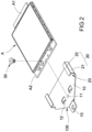
FIG. 2 is an exploded three-dimensional diagram of an expansion structure and an electronic card of the present invention; -
FIG. 3 is a section diagram of an expansion structure and an electronic card according to another embodiment of the present invention; -
FIG. 4 is an exploded three-dimensional diagram of an electronic card and a circuit board; -
FIG. 5 is an exploded three-dimensional diagram of an expansion structure and a circuit board of the present invention; and -
FIG. 6 is a three-dimensional appearance diagram of an expansion structure and a circuit board of the present invention. - Details and technical contents of the present invention are given with the accompanying drawings below. It should be noted that the accompanying drawings are for illustration purposes and are not to be construed as limitations to the present invention.
- The present invention provides an expansions structure for an electronic card for installing an electronic card A. Referring to
FIG. 1 andFIG. 2 , the expansion structure primarily includes acarrier board 10, at least one limitingmember 20 and a fixingelement 30. - In this embodiment, the electronic card A is a 4G mobile communication chip (for example, a SIM card); however, the present invention is not limited to the example above. For example, the electronic card A may also be a 3G, LTE or 5G mobile communication chip.
- The
carrier board 10 carries a part of a bottom surface of the electronic card A. Preferably, thecarrier board 10 carries at least one-third of the area of the bottom surface of the electronic card A, such that the electronic card A is effectively carried by thecarrier board 10. In this embodiment, thecarrier board 10 is substantially a plate-like stainless steel metal element; however, the present invention is not limited to the example above. For example, thecarrier board 10 may also be other metal plates or plastic plates having certain strength. - The limiting
member 20 includes asidewall 21 and a blockingpiece 22 vertically extended from thesidewall 21. The sidewall 21 s formed on one side of thecarrier board 10, and thesidewall 21, blockingpiece 22 and thecarrier board 10 jointly define a slidingchannel 23 for accommodating the electronic card A. In this embodiment, the number of the limitingmember 20 is two, and the two limitingmembers 20 are respectively disposed on two sides of thecarrier board 10. Thus, the slidingchannels 23 formed at the limitingmembers 20 can respectively cover left and right sides of the electronic card A, thereby limiting horizontal movement and axial movement of the electronic card A such that the electronic card A is allowed to slide only in the vertical direction. - The fixing
element 30 fixes the electronic card A on thecarrier board 10. In this embodiment, the fixingelement 30 is a screw bolt, thecarrier board 10 is provided with alock hole 11, and the screw bolt passes through the electronic card A and is locked at thelock hole 11, thereby clamping and securing the electronic card A on thecarrier board 10; however, the present invention is not limited to the examples above. Referring toFIG. 3 showing an expansion structure according to another embodiment of the present invention, the fixingelement 30 may also be an elastic piece disposed on thecarrier board 10, wherein the elastic piece is a metal piece capable of clamping the electronic card A on thecarrier board 10 by its elasticity. Preferably, a front end of the elastic piece may be an arc to facilitate the electronic card A to be smoothly inserted along the arc and be clamped by pushing the elastic piece upward. - In addition, the
carrier board 10 is provided with at least one stoppingelement 12 in a protruding manner, wherein the stoppingelement 12 stops at one end of each slidingchannel 23 into which the electronic card A is inserted. More specifically, the stoppingelement 12 vertically stops the electronic card A, so that the electronic card A is allowed to be pushed to an expected location and be fixed by the fixingelement 30. In this embodiment, the stoppingelement 12 is a metal piece formed by stamping and bending thecarrier board 10, the number of the stoppingelement 12 is two, and the two stoppingelements 12 are respectively located on left and right sides of the lockinghole 11; however, the present invention is not limited to the examples above. For example, the stoppingelement 12 may also be a welded metal piece or metal block, and the number of the stoppingelement 12 may be one, given that the electronic card A is provided with a stopping effect. - The present invention further provides an electronic device primarily including a housing (not shown), a
circuit board 50, an electronic card A, theexpansion structure 100 described above, and atightening component 60. - Referring to
FIG. 4 , thecircuit board 50 is disposed in the housing (not shown), aconnector slot 51 and a connectingcolumn 52 are disposed on thecircuit board 50, and the electronic card A inFIG. 4 is a 5G mobile communication chip having an insertion end A1 and a fixing end A2 on two ends thereof, respectively. The insertion end A1 of the electronic card A is correspondingly plugged with theconnector slot 51, and the fixing end A2 of the electronic card A is fixed at the connectingcolumn 52 by the tighteningcomponent 60. In this embodiment, the tighteningcomponent 60 is a screw bolt, the connectingcolumn 52 is a screw stud having ascrew hole 521, the fixing end A2 has a fixing hole, and the screw bolt passes through the fixing hole of the 5G electronic card A and is locked at thescrew hole 521 of the screw stud; however, the present invention is not limited to the examples above. - Referring to
FIG. 5 andFIG. 6 , thecircuit board 50 is provided with theconnector slot 51 and the connectingcolumn 52 described above, and the electronic card A inFIG. 5 andFIG. 6 is a 4G mobile communication chip being smaller in size than a 5G mobile communication chip; however, the present invention is not limited to the examples above. For example, the electronic card A of this embodiment may also be a 3G or LTE mobile communication chip, given that the lengthwise dimension is less than that of the 5G mobile communication chip. The electronic card A is installed on theexpansions structure 100 and has an insertion end A1, wherein the insertion end A1 is located on one end of the electronic card A away from the fixingelement 30. Theexpansion structure 100 is disposed on thecircuit board 50, so as to achieve an electrical connection between the insertion end A1 and theconnector slot 51 connected to each other for signal transmission. - In addition, the
carrier board 10 is provided with a throughhole 13, and the tighteningcomponent 60 passes through the throughhole 13 and is tightened with the connectingcolumn 52, thereby fixing theexpansion structure 100 on thecircuit board 50. In this embodiment, the tighteningcomponent 60 is a screw bolt, the connectingcolumn 52 is a screw stud having ascrew hole 521, the screw bolt passes through the throughhole 13 of thecarrier board 10 and is locked at thescrew hole 521 of the screw stud; however, the present invention is not limited to the examples above. For example, the tighteningcomponent 60 may also be a cap positioning pin, the connectingcolumn 52 may be a column having a positioning hole, and the cap positioning pin and the positioning hole are tightly packed so as to clamp and secure thecarrier board 10 of theexpansion structure 100 on the connectingcolumn 52 by the cap positioning pin. - Thus, the small-size 4G mobile communication chip can be installed on the
expansion structure 100 for length expansion, and the small-size 4G mobile communication chip can then be installed on the installation interface of the large-size 5G mobile communication chip, thereby allowing the differently-sized electronic card A to share the installation interface of thesame circuit board 50. Moreover, while a user uses an electronic device, the user is allowed to conveniently and quickly replace the desired electronic card A without needing to also replace theentire circuit board 50. - It should be noted that, the assembly method for the electronic device and the
expansion structure 100 of the present invention includes the following steps. First of all, one end of the electronic card A away from the insertion end A1 is inserted into the two slidingchannels 23 on the left and right sides of thecarrier board 10, and the electronic card A is pushed vertically until being stopped and positioned by the stoppingelements 12. Then, the electronic card A is fixed on thecarrier board 10 by the fixingelement 30 to thereby form theexpansion structure 100. The insertion end A1 and theconnector slot 51 are connected to each other, and the tighteningcomponent 60 passes through the throughhole 13 and is fixed with the connectingcolumn 52, thereby fixing theexpansion structure 100 on thecircuit board 50 to complete the assembly. - In conclusion, the invention is industrially applicable and novel, involves an inventive step, and meets the requirements of a patent application. Therefore, a patent application is filed accordingly. The present invention may be implemented by many other possible embodiments. Without departing from the spirit and the substantiveness of the present invention, various changes and modifications may be made by a person skilled in the art on the basis of the disclosure. It should be noted that, such corresponding changes and modifications are to be encompassed with the scope of protection of the appended claims.
Claims (15)
- An expansion structure for an electronic card, for installing the electronic card, the expansion structure comprising:a carrier board, carrying the electronic card;at least one limiting member, comprising a sidewall and a blocking piece extended from the sidewall, the sidewall formed on one side of the carrier board, and the sidewall, the blocking piece and the carrier board jointly defining a sliding channel for accommodating the electronic card; anda fixing element, fixing the electronic card at the carrier board.
- The expansion structure according to claim 1, wherein the fixing element is a screw bolt, the carrier board is provided with a locking hole, and the screw bolt passes through the electronic card and is locked at the locking hole.
- The expansion structure according to claim 1, wherein the fixing element is an elastic piece, and the elastic piece is disposed at the carrier board and elastically clamps and secures the electronic card.
- The expansion structure according to claim 1, wherein the carrier board carries at least one-third of an area of a bottom surface of the electronic card.
- The expansion structure according to claim 1, wherein the carrier board is provided with a stopping element in a protruding manner, and the stopping element stops at one end of the electronic card.
- An electronic device, for installing an electronic card, the electronic card having an insertion end, the electronic device comprising:a circuit board, provided with a connector slot; andan expansion structure, comprising a carrier board and a fixing element;wherein, the electronic card is disposed at the carrier board and is fixed by the fixing element, a sidewall is formed on a side of the carrier board, a blocking piece is extended inward from the sidewall, the blocking piece and the sidewall jointly cover the side of the electronic card, and the expansion structure is disposed at the circuit board and connects the connection end and the connector slot with each other.
- The electronic device according to claim 6, further comprising:a tightening component;wherein, the circuit board is provided with a connecting column in a protruding manner, the carrier board is provided with a through hole, and the tightening component passes through the through hole and is tightened with the connecting column.
- The electronic device according to claim 6, wherein the fixing element is a screw bolt, the carrier board is provided with a locking hole, and the screw bolt passes through the electronic card and is locked at the locking hole.
- The electronic device according to claim 6, wherein the fixing element is an elastic piece, and the elastic piece is disposed at the carrier board and elastically clamps and secures the electronic card.
- The electronic device according to claim 6, wherein the carrier board is provided with a stopping element in a protruding manner, and the stopping element stops at one end of the electronic card away from the insertion end.
- An assembly method for assembling an expansion structure for an electronic device, comprising:providing an electronic device, a carrier board, a fixing element and an electronic card; wherein the electronic device is provided with a circuit board, the circuit board is provided with a connector slot, a sidewall is formed on a side of the carrier board, a blocking piece is extended from the sidewall, the carrier board, the sidewall and the blocking piece jointly define a sliding channel, and the electronic device has an insertion end;inserting one end of the electronic card away from the insertion end into the sliding channel to install the electronic card at the carrier board;fixing the electronic card on the carrier board by the fixing element to form an expansion structure; andconnecting the insertion end and the connector slot with each other to fix the expansion structure on the circuit board.
- The assembly method according to claim 11, wherein the carrier board is provided with a stopping element in a protruding manner, and when the one end of the electronic card away from the insertion end is inserted into the sliding channel, the electronic card is pushed until being stopped and positioned by the stopping element.
- The assembly method according to claim 11, wherein the fixing element is a screw bolt, the carrier board is provided with a locking hole, and the screw bolt passes through the electronic card and is locked at the locking hole.
- The assembly method according to claim 11, wherein the fixing element is an elastic piece, and the elastic piece is provided at the carrier board and elastically clamps and secures the electronic card.
- The assembly method according to claim 11, further comprising:providing a tightening component;wherein, the circuit board is provided with a connecting column, the carrier board is provided with a through hole, and after the insertion end and the connector slot are connected with each other, the tightening component passes through the through hole and is fixed with the connecting column.
Applications Claiming Priority (1)
| Application Number | Priority Date | Filing Date | Title |
|---|---|---|---|
| CN202111474967.XA CN116231347A (en) | 2021-12-03 | 2021-12-03 | Extended structure of electronic card, electronic device and assembly method thereof |
Publications (2)
| Publication Number | Publication Date |
|---|---|
| EP4191378A2 true EP4191378A2 (en) | 2023-06-07 |
| EP4191378A3 EP4191378A3 (en) | 2023-08-23 |
Family
ID=84370065
Family Applications (1)
| Application Number | Title | Priority Date | Filing Date |
|---|---|---|---|
| EP22210865.6A Pending EP4191378A3 (en) | 2021-12-03 | 2022-12-01 | Electronic device, expansion structure for electronic card and assembly method thereof |
Country Status (4)
| Country | Link |
|---|---|
| EP (1) | EP4191378A3 (en) |
| CN (1) | CN116231347A (en) |
| AU (1) | AU2022279547B2 (en) |
| TW (1) | TWI857384B (en) |
Cited By (1)
| Publication number | Priority date | Publication date | Assignee | Title |
|---|---|---|---|---|
| TWI858924B (en) * | 2023-09-18 | 2024-10-11 | 英業達股份有限公司 | Electronic module mounting structure |
Families Citing this family (1)
| Publication number | Priority date | Publication date | Assignee | Title |
|---|---|---|---|---|
| CN117202605B (en) * | 2023-08-17 | 2025-09-05 | 南京佳力图机房环境技术股份有限公司 | A pull-out structure for an electrical box of an inter-row air-conditioning refrigeration system |
Citations (3)
| Publication number | Priority date | Publication date | Assignee | Title |
|---|---|---|---|---|
| CN206892773U (en) * | 2017-06-14 | 2018-01-16 | 环达电脑(上海)有限公司 | M.2 adapter card fixing device |
| US10152097B1 (en) * | 2017-09-29 | 2018-12-11 | Adata Technology Co., Ltd. | Heat-dissipating device for expansion card and expansion card assembly with heat-dissipating function |
| EP3612010A1 (en) * | 2018-08-13 | 2020-02-19 | Baidu USA LLC | Retaining tray for retaining an m.2 compatible device used in autonomous driving vehicles |
Family Cites Families (10)
| Publication number | Priority date | Publication date | Assignee | Title |
|---|---|---|---|---|
| JP2001307801A (en) * | 2000-04-17 | 2001-11-02 | Kuurii Components Kk | Connector for memory card |
| TW568513U (en) * | 2003-01-29 | 2003-12-21 | Shiou-Rung Chen | Expansion card of removable anti-EMI structure |
| TWM286558U (en) * | 2005-11-01 | 2006-01-21 | E Move Technology Co Ltd | Fastening structure for electronic card |
| TWM289916U (en) * | 2005-11-15 | 2006-04-21 | Tsz-Huei Shiu | Fixing structure of electronic structure |
| TWI433639B (en) * | 2011-09-15 | 2014-04-01 | Wistron Corp | Circuit board device and combined structure thereof with electronic card |
| TWI543694B (en) * | 2014-12-05 | 2016-07-21 | Giga Byte Tech Co Ltd | Expansion card fixing structure |
| TWM541594U (en) * | 2016-12-29 | 2017-05-11 | Super Micro Computer Inc | Add-on card fixer |
| CN107977054B (en) * | 2017-11-22 | 2020-12-29 | 英业达科技有限公司 | Mainboard assembly |
| CN110275578A (en) * | 2018-03-15 | 2019-09-24 | 环达电脑(上海)有限公司 | Flash card support Design |
| CN111221395B (en) * | 2018-11-27 | 2021-09-21 | 技嘉科技股份有限公司 | Radiating assembly of M.2 expansion card and electronic device |
-
2021
- 2021-12-03 CN CN202111474967.XA patent/CN116231347A/en active Pending
-
2022
- 2022-11-01 TW TW111141643A patent/TWI857384B/en active
- 2022-12-01 EP EP22210865.6A patent/EP4191378A3/en active Pending
- 2022-12-02 AU AU2022279547A patent/AU2022279547B2/en active Active
Patent Citations (3)
| Publication number | Priority date | Publication date | Assignee | Title |
|---|---|---|---|---|
| CN206892773U (en) * | 2017-06-14 | 2018-01-16 | 环达电脑(上海)有限公司 | M.2 adapter card fixing device |
| US10152097B1 (en) * | 2017-09-29 | 2018-12-11 | Adata Technology Co., Ltd. | Heat-dissipating device for expansion card and expansion card assembly with heat-dissipating function |
| EP3612010A1 (en) * | 2018-08-13 | 2020-02-19 | Baidu USA LLC | Retaining tray for retaining an m.2 compatible device used in autonomous driving vehicles |
Cited By (1)
| Publication number | Priority date | Publication date | Assignee | Title |
|---|---|---|---|---|
| TWI858924B (en) * | 2023-09-18 | 2024-10-11 | 英業達股份有限公司 | Electronic module mounting structure |
Also Published As
| Publication number | Publication date |
|---|---|
| AU2022279547A1 (en) | 2023-06-22 |
| TW202325128A (en) | 2023-06-16 |
| TWI857384B (en) | 2024-10-01 |
| AU2022279547B2 (en) | 2024-03-07 |
| CN116231347A (en) | 2023-06-06 |
| EP4191378A3 (en) | 2023-08-23 |
Similar Documents
| Publication | Publication Date | Title |
|---|---|---|
| AU2022279547B2 (en) | Electronic Device, Expansion Structure For Electronic Card And Assembly Method Thereof | |
| US10008796B1 (en) | Connector structure | |
| US9705269B2 (en) | USB socket connector | |
| US10064318B2 (en) | Shield can assembly and electronic device including the same | |
| CN211210044U (en) | Electronic equipment and circuit board assembly thereof | |
| US20100149780A1 (en) | Shielding assembly and electronic device utilizing the same | |
| US9936595B2 (en) | Wire retention cover for printed circuit boards in an electronic device | |
| US20090174997A1 (en) | Expansion card module | |
| US20110186696A1 (en) | Clip and shield device using the same | |
| US20130021743A1 (en) | Expansion card mounting assembly | |
| US9372514B2 (en) | Apparatus for fastening expansion card | |
| US20120289096A1 (en) | Electrical connector | |
| US11769966B2 (en) | Anti-attenuation apparatus and plug | |
| US10139872B1 (en) | Motherboard assembly and retainer thereof | |
| US10658769B1 (en) | Electronic device | |
| EP3618198A1 (en) | Fixed structure for battery connector, and mobile terminal | |
| US12184323B2 (en) | Electronic device, expansion structure for electronic card and assembly method thereof | |
| US8939780B2 (en) | Connector structure and electronic device having the same | |
| US20140322961A1 (en) | Connector assembly | |
| CN205071252U (en) | Mobile terminal and loudspeaker | |
| JP2003243100A (en) | Connector device | |
| CN104009320B (en) | Bus tie | |
| CN101739537A (en) | Positioning structure for subscriber identification module card | |
| US20140376999A1 (en) | Expansion card mounting assembly | |
| US20150200482A1 (en) | Sim card connector and electronic device including the same |
Legal Events
| Date | Code | Title | Description |
|---|---|---|---|
| PUAI | Public reference made under article 153(3) epc to a published international application that has entered the european phase |
Free format text: ORIGINAL CODE: 0009012 |
|
| STAA | Information on the status of an ep patent application or granted ep patent |
Free format text: STATUS: THE APPLICATION HAS BEEN PUBLISHED |
|
| AK | Designated contracting states |
Kind code of ref document: A2 Designated state(s): AL AT BE BG CH CY CZ DE DK EE ES FI FR GB GR HR HU IE IS IT LI LT LU LV MC ME MK MT NL NO PL PT RO RS SE SI SK SM TR |
|
| PUAL | Search report despatched |
Free format text: ORIGINAL CODE: 0009013 |
|
| AK | Designated contracting states |
Kind code of ref document: A3 Designated state(s): AL AT BE BG CH CY CZ DE DK EE ES FI FR GB GR HR HU IE IS IT LI LT LU LV MC ME MK MT NL NO PL PT RO RS SE SI SK SM TR |
|
| RIC1 | Information provided on ipc code assigned before grant |
Ipc: G06F 1/18 20060101AFI20230714BHEP |
|
| STAA | Information on the status of an ep patent application or granted ep patent |
Free format text: STATUS: REQUEST FOR EXAMINATION WAS MADE |
|
| 17P | Request for examination filed |
Effective date: 20240209 |
|
| RBV | Designated contracting states (corrected) |
Designated state(s): AL AT BE BG CH CY CZ DE DK EE ES FI FR GB GR HR HU IE IS IT LI LT LU LV MC ME MK MT NL NO PL PT RO RS SE SI SK SM TR |
|
| STAA | Information on the status of an ep patent application or granted ep patent |
Free format text: STATUS: EXAMINATION IS IN PROGRESS |
|
| 17Q | First examination report despatched |
Effective date: 20250728 |