EP4191310A1 - Method for manufacturing intermittent connection-type optical fiber tape core wire and intermittent connection-type optical fiber tape core wire - Google Patents
Method for manufacturing intermittent connection-type optical fiber tape core wire and intermittent connection-type optical fiber tape core wire Download PDFInfo
- Publication number
- EP4191310A1 EP4191310A1 EP21849845.9A EP21849845A EP4191310A1 EP 4191310 A1 EP4191310 A1 EP 4191310A1 EP 21849845 A EP21849845 A EP 21849845A EP 4191310 A1 EP4191310 A1 EP 4191310A1
- Authority
- EP
- European Patent Office
- Prior art keywords
- optical fibers
- optical fiber
- coupling resin
- fiber ribbon
- less
- Prior art date
- Legal status (The legal status is an assumption and is not a legal conclusion. Google has not performed a legal analysis and makes no representation as to the accuracy of the status listed.)
- Granted
Links
Images


Classifications
-
- G—PHYSICS
- G02—OPTICS
- G02B—OPTICAL ELEMENTS, SYSTEMS OR APPARATUS
- G02B6/00—Light guides; Structural details of arrangements comprising light guides and other optical elements, e.g. couplings
- G02B6/44—Mechanical structures for providing tensile strength and external protection for fibres, e.g. optical transmission cables
- G02B6/4479—Manufacturing methods of optical cables
- G02B6/448—Ribbon cables
-
- G—PHYSICS
- G02—OPTICS
- G02B—OPTICAL ELEMENTS, SYSTEMS OR APPARATUS
- G02B6/00—Light guides; Structural details of arrangements comprising light guides and other optical elements, e.g. couplings
- G02B6/24—Coupling light guides
- G02B6/36—Mechanical coupling means
- G02B6/38—Mechanical coupling means having fibre to fibre mating means
- G02B6/3801—Permanent connections, i.e. wherein fibres are kept aligned by mechanical means
-
- G—PHYSICS
- G02—OPTICS
- G02B—OPTICAL ELEMENTS, SYSTEMS OR APPARATUS
- G02B6/00—Light guides; Structural details of arrangements comprising light guides and other optical elements, e.g. couplings
- G02B6/24—Coupling light guides
- G02B6/36—Mechanical coupling means
- G02B6/40—Mechanical coupling means having fibre bundle mating means
-
- G—PHYSICS
- G02—OPTICS
- G02B—OPTICAL ELEMENTS, SYSTEMS OR APPARATUS
- G02B6/00—Light guides; Structural details of arrangements comprising light guides and other optical elements, e.g. couplings
- G02B6/44—Mechanical structures for providing tensile strength and external protection for fibres, e.g. optical transmission cables
- G02B6/4401—Optical cables
- G02B6/4403—Optical cables with ribbon structure
Definitions
- the present disclosure relates to a method for manufacturing an intermittently coupled-type optical fiber ribbon and an intermittently coupled-type optical fiber ribbon.
- Patent Literatures 1 and 4 describe a distance between optical fibers (center-to-center distance) of a ribbon having an intermittent structure.
- a method for manufacturing an intermittently coupled-type optical fiber ribbon of the present disclosure includes:
- An intermittently coupled-type optical fiber ribbon according to the present disclosure includes:
- each optical fiber In order to densely mount a plurality of optical fiber ribbons in a cable, it is preferable to arrange each optical fiber such that a distance between adjacent optical fibers is as small as possible in each optical fiber ribbon. However, when the distance is too small, the optical fibers may be damaged by a cleaving blade in the case of forming a slit.
- a coating layer of the thin optical fiber is thin, and a distance between adjacent thin optical fibers is small, and thus when an insertion position of the cleaving blade deviates even slightly in the case of forming a slit, the thin optical fiber may be externally damaged.
- the present disclosure provides a method for manufacturing an intermittently coupled-type optical fiber ribbon and an intermittently coupled-type optical fiber ribbon that can be densely mounted while preventing an external damage to an optical fiber.
- a method for manufacturing an intermittently coupled-type optical fiber ribbon and an intermittently coupled-type optical fiber ribbon that can be densely mounted while preventing an external damage to an optical fiber are provided.
- Fig. 1 is a configuration diagram of a manufacturing device 100 of the intermittently coupled-type optical fiber ribbon 1 according to an aspect of the present disclosure.
- the manufacturing device 100 includes a supply 101, a coating device 110, a feeding capstan 115, a cutting device 116, a winding-up tension control dancer 118, and a winding-up device 119.
- the manufacturing device 100 includes a fiber assembling roller 105 provided between the supply 101 and the coating device 110, and a turn roller 114 provided between the coating device 110 and the feeding capstan 115.
- the supply 101 includes a plurality of reels 102, a dancer roller 103, and a conveying roller 104.
- Optical fibers 11 are wrapped around the plurality of reels 102.
- An outer diameter of each of the optical fibers 11 is, for example, 220 ⁇ m or less.
- the plurality of optical fibers 11 are drawn out from the plurality of reels 102, and a predetermined tension is applied to the plurality of optical fibers 11 by the dancer roller 103. Thereafter, the plurality of optical fibers 11 are arranged on an array surface in the case of passing through the conveying roller 104 and sent to the fiber assembling roller 105.
- a plurality of groove portions (not shown) through which the plurality of optical fibers 11 pass are arranged at predetermined intervals on the fiber assembling roller 105.
- the plurality of optical fibers 11 are assembled and arranged in parallel in a direction orthogonal to a longitudinal direction of the optical fibers 11.
- the plurality of optical fibers 11 assembled on the fiber assembling roller 105 are sent to the coating device 110.
- the coating device 110 includes a resin storage tank 111, an applying device 112, and an ultraviolet irradiation device 113.
- the applying device 112 penetrates all the optical fibers 11 and coats, around the optical fibers 11, a coupling resin 15 supplied from the resin storage tank 111 to form a coating layer 12 (see Fig. 2 ).
- the coupling resin 15 is preferably an ultraviolet curable resin, and may be a thermoplastic resin, an adhesive resin, or other coating resins.
- the ultraviolet irradiation device 113 cures the coupling resin 15 by emitting ultraviolet rays. As a result, the plurality of optical fibers 11 are formed into an optical fiber ribbon 10.
- the optical fiber ribbon 10 is sent to the feeding capstan 115 via the turn roller 114. Thereafter, slits are formed in the optical fiber ribbon 10 by the cutting device 116.
- the cutting device 116 includes a plurality of cleaving blades 117.
- Each cleaving blade 117 has a tapered tip and a blade thickness of 0.2 mm, for example.
- a cam mechanism is coupled to each cleaving blade 117, and the cleaving blade 117 is provided along a longitudinal direction of the optical fiber ribbon 10 and is configured to swing in conjunction with the cam mechanism.
- Slits are formed by intermittently inserting the cleaving blade 117 into the coupling resin 15 between some adjacent optical fibers of the optical fiber ribbon 10 by the swinging movement of the cleaving blade 117.
- the cleaving blade 117 is preferably inserted in a state in which the coupling resin 15 is cured to a gel fraction of 90% or more.
- the optical fiber ribbon 10 in which the slits are intermittently formed is formed into the intermittently coupled-type optical fiber ribbon 1.
- the intermittently coupled-type optical fiber ribbon 1 is sent to the winding-up tension control dancer 118 to control a tension. Thereafter, the intermittently coupled-type optical fiber ribbon 1 is wound up onto a winding-up reel R by the winding-up device 119.
- Fig. 2 shows a cross-sectional view perpendicular to the longitudinal direction of the optical fiber ribbon 10.
- a periphery of each of a plurality of optical fibers 11A to 11L (12 cores in this example) arranged in parallel in a direction orthogonal to the longitudinal direction is coated with the coating layer 12.
- a breaking strength of the coupling resin 15 forming the coating layer 12 is more than 20 MPa and 50 MPa or less.
- Each of the optical fibers 11A to 11L includes a glass fiber 16 in the center and an outer layer 17 (outermost layer) covering a periphery of the glass fiber 16.
- a diameter of the glass fiber 16 is, for example, 200 ⁇ m, and a thickness of the outer layer 17 is 37.5 ⁇ m.
- a Young's modulus of the outer layer 17 is 800 MPa or more and 2000 MPa or less.
- the interval of distance g is provided between a set of the optical fibers 11A and 11B and a set of the optical fibers 11C and 11D, between a set of the optical fibers 11C and 11D and a set of the optical fibers 11E and 11F, between a set of the optical fibers 11E and 11F and a set of the optical fibers 11G and 11H, between a set of the optical fibers 11G and 11H and a set of the optical fibers 11I and 11J, and between a set of the optical fibers 11I and 11J and a set of the optical fibers 11L and 11L.
- the interval of distance g is provided for every two optical fibers in this example, but the interval of distance g may be provided for each optical fiber.
- the distance g is a distance between the outer layer 17 of an optical fiber (11B) and the outer layer 17 of an adjacent optical fiber (11C) on a straight line L which is along a parallel arrangement direction of the plurality of optical fibers 11A to 11L, and passes through centers of the optical fibers, the optical fiber (11B) being near an adjacent optical fiber set (for example, 11C and 11D) in a set of optical fibers (for example, 11A and 11B).
- the distance g is 10 ⁇ m or more and 100 ⁇ m or less.
- a slit is formed by inserting the cleaving blade 117 into a portion of the coupling resin 15 where the interval of distance g is provided. As a result, the slit is formed into a non-coupling portion 14 (see Fig. 3 ) of the intermittently coupled-type optical fiber ribbon 1.
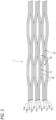
- Fig. 3 is a partially developed view showing the intermittently coupled-type optical fiber ribbon 1 in a longitudinal direction thereof.
- the optical fiber ribbon 10 that has passed through the cutting device 116 is formed into the intermittently coupled-type optical fiber ribbon 1.
- a coupling portion 13 in which adjacent optical fibers are coupled and the non-coupling portion 14 in which adjacent optical fibers are not coupled are intermittently provided in the longitudinal direction on some or all of the plurality of optical fibers 11A to 11L in a state of being arranged in parallel in a direction orthogonal to a longitudinal direction of the plurality of optical fibers 11A to 11L.
- the optical fiber ribbon 10 sent to the cutting device 116 is formed into the intermittently coupled-type optical fiber ribbon 1 by intermittently inserting the cleaving blade 117.
- the optical fibers 11 are arranged so that the distance g is 10 ⁇ m or more and 100 ⁇ m or less, and the coupling resin 15 is cured.
- the glass fiber 16 may be damaged by the cleaving blade 117 in the case of inserting the cleaving blade 117.
- the plurality of optical fibers 11 cannot be densely arranged as the optical fiber ribbon 10.
- the distance g is 10 ⁇ m or more, even when the cleaving blade 117 is inserted, a risk of damaging the optical fibers 11 is reduced.
- the plurality of optical fibers 11 can be densely arranged as the optical fiber ribbon 10. Therefore, it is possible to provide the intermittently coupled-type optical fiber ribbon 1 in which the optical fibers 11 are densely arranged while reducing a possibility of an external damage to each optical fiber 11.
- the breaking strength of the coupling resin 15 is preferably neither too low nor too high.
- the breaking strength is too low, for example, in the case where the optical fiber ribbon 10 is squeezed by the turn roller 114, since the coupling resin 15 is too soft, the plurality of optical fibers 11 in the optical fiber ribbon 10 may be separated.
- the breaking strength is too high, since the coupling resin 15 is too hard, it is difficult to break the coupling resin 15 by the cleaving blade 117.
- the breaking strength of the coupling resin 15 is more than 20 MPa, separation of the optical fibers 11 due to a low breaking strength is less likely to occur.
- the breaking strength of the coupling resin 15 is 50 MPa or less, the coupling resin 15 is not too hard, and the coupling resin 15 can be easily broken by the cleaving blade 117. Therefore, it is possible to easily form the slit, that is, the non-coupling portion 14 while preventing the separation of the optical fibers 11.
- the glass fiber 16 may be damaged by the cleaving blade 117 in the case of inserting the cleaving blade 117.
- the Young's modulus of the outer layer 17 is too high (the outer layer 17 is too hard), it is difficult to cause the intermittently coupled-type optical fiber ribbon to deform due to a rigidity of the resin, and a cable loss characteristic may deteriorate.
- the Young's modulus of the outer layer 17 of each optical fiber 11 in this example is 800 MPa or more, the outer layer 17 is less likely to be externally damaged by the cleaving blade 117.
- the Young's modulus of the outer layer 17 is 2000 MPa or less, it is not difficult to cause the intermittently coupled-type optical fiber ribbon 1 to deform due to a rigidity of the resin, and a possibility of deterioration in cable loss characteristic can be reduced. Therefore, it is possible to provide the intermittently coupled-type optical fiber ribbon 1 that prevents an external damage to the outer layer 17 and has a good cable loss characteristic.
- the cleaving blade 117 is inserted into the coupling resin 15 to form a slit after the coupling resin 15 is cured to a predetermined value or more.
- the coupling resin 15 is highly elastic, it is difficult to break the coupling resin 15.
- the coupling resin 15 is not cured, since the strength is low, and the plurality of optical fibers 11 in the optical fiber ribbon 10 may be separated.
- the coupling resin 15 can be easily broken by the cleaving blade 117, and separation of the optical fibers 11 within the ribbon can also be prevented.
- the manufacturing process is described as forming the intermittently coupled-type optical fiber ribbon 1 by intermittently inserting the cleaving blade 117 of the cutting device 116 into the optical fiber ribbon 10 as it is in which the coupling resin 15 is cured by the coating device 110, but the manufacturing process is not limited to this.
- the manufacturing device 100 may include a first heating unit 121 ( Fig. 1 ) that heats the coupling resin 15 between the coating device 110 and the cutting device 116.
- the coupling resin 15 is heated and softened by the first heating unit 121.
- a slit is formed by inserting the cleaving blade 117 into the softened coupling resin 15.
- a temperature heated by the first heating unit 121 is preferably about 40°C or higher. When the heated temperature is about 40°C, an effect of softening the coupling resin 15 is observed. However, the heated temperature needs to be equal to or lower than a melting point of the coupling resin 15, and specifically, the heated temperature is preferably about 95°C or lower.
- the cutting device 116 of the manufacturing device 100 may include a second heating unit 122 that heats the cleaving blade 117 ( Fig. 1 ).
- the optical fiber ribbon 10 in which the coupling resin 15 is cured by passing through the ultraviolet irradiation device 113 of the coating device 110 is sent to the cutting device 116.
- the cleaving blade 117 heated by the second heating unit 122 is inserted into the cured coupling resin 15 to form a slit. Therefore, according to this example, even when the coupling resin 15 is cured, since the cleaving blade 117 is inserted into the coupling resin 15 in a heated state of the cleaving blade 117, the coupling resin 15 can be easily broken.
- a temperature heated by the second heating unit 122 is preferably about 40°C or higher and about 95°C or lower. It should be noted that both the first heating unit 121 and the second heating unit 122 may be provided to respectively heat both the coupling resin 15 and the cleaving blade 117.
- the manufacturing device 100 of this example may mark the plurality of optical fibers 11 with a mark M in order to enhance identification of the intermittently coupled-type optical fiber ribbon 1.
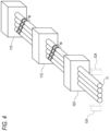
- Fig. 4 is a schematic diagram of a printing device 123 that can be provided on the manufacturing device 100 of the intermittently coupled-type optical fiber ribbon 1.
- the manufacturing device 100 may include the printing device 123 that marks surfaces of the plurality of optical fibers 11, in addition to the configuration shown in Fig. 1 .
- the printing device 123 may be disposed between the supply 101 and the coating device 110, and preferably provided between the fiber assembling roller 105 and the coating device 110.
- the printing device 123 is, for example, an inkjet printer.
- the printing device 123 forms the mark M by printing markings on the surfaces of the plurality of optical fibers 11 sent from the supply 101.
- a shape of the mark M may be, for example, a bar shape orthogonal to the longitudinal direction.
- each of the optical fibers 11 may be provided with a ring-shaped ring mark.
- the plurality of optical fibers 11 having the mark M formed thereon are then sent to the applying device 112.
- the applying device 112 applies the coupling resin 15 onto the mark M, and the ultraviolet irradiation device 113 cures the coupling resin 15 including the mark M. Since subsequent manufacturing processes overlap with the manufacturing processes described in Fig. 1 , illustration and description thereof will be omitted.
- the identification of the ribbon can be enhanced.
- the manufacturing device 100 of this example may include a plasma processing device 124 that performs plasma processing on the surfaces of the plurality of optical fibers 11.
- the plasma processing device 124 may be disposed between the supply 101 and the printing device 123, and preferably provided between the fiber assembling roller 105 and the printing device 123.
- the plasma processing by the plasma processing device 124 enhances a wettability of the surface of each optical fiber and improves a degree of adhesion of a marking material to the surface of the optical fiber. Therefore, it is possible to prevent the mark M from peeling off from the surface of the optical fiber when the mark M is marked by the printing device 123 thereafter.
- the optical fiber cable manufactured by the manufacturing method of the present disclosure was evaluated.
- the optical fiber cable used in this evaluation experiment is a 432-core slotless type optical fiber cable in which 12-core intermittently coupled-type optical fiber ribbon 1 is mounted.
- An outer diameter of the cable is 11 mm and a core density is 4.55 cores/mm 2 .
- the distance g of the intermittently coupled-type optical fiber ribbon 1 mounted on each optical fiber cable, the breaking strength of the coupling resin 15 at 23°C, and the Young's modulus of the outer layer at 23°C are individually set, and Sample Nos. 1 to 12 were prepared.
- the optical fiber was separated at the time of cleaving in Sample No. 4 in which the breaking strength of the coupling resin 15 is 20 MPa. No separation was confirmed in other samples. Accordingly, it was confirmed that when the breaking strength of the coupling resin 15 is more than 20 MPa, the optical fiber can be prevented from being separated at the time of cleaving.
- the distance g was 150 ⁇ m, and an attenuation of 0.3 dB/km or more was confirmed as a cable loss characteristic.
- the distance g is too long, optical fibers in the optical fiber of the same core wire cannot be densely mounted in the cable. That is, since a cross-sectional area per intermittently coupled-type optical fiber ribbon increases, the optical fibers in the cable are mounted without any gap such that lateral pressure is applied to each other. This lateral pressure increases the cable loss characteristic.
- the cable loss characteristic was less than 0.3 dB/km in other Sample Nos. 1-7 and 9-13 in which the distance g is 100 ⁇ m or less.
- the cable loss characteristic was also less than 0.3 dB/km in Sample No. 7 in which the distance g is 100 ⁇ m or less, and the Young's modulus of the outer layer is 2000 MPa. Accordingly, it was confirmed that when the distance g is 100 ⁇ m or less and the Young's modulus of the outer layer is 2000 MPa or less, an optical fiber cable having a low cable loss characteristic can be achieved while optical fibers are densely mounted in the cable.
Landscapes
- Physics & Mathematics (AREA)
- General Physics & Mathematics (AREA)
- Optics & Photonics (AREA)
- Engineering & Computer Science (AREA)
- Manufacturing & Machinery (AREA)
- Optical Fibers, Optical Fiber Cores, And Optical Fiber Bundles (AREA)
- Mechanical Coupling Of Light Guides (AREA)
Abstract
Description
- The present disclosure relates to a method for manufacturing an intermittently coupled-type optical fiber ribbon and an intermittently coupled-type optical fiber ribbon.
- The present application claims priority from
Japanese Patent Application No. 2020-128531 filed on July 29, 2020 - In the related art, as an example of a method for manufacturing an intermittently coupled-type optical fiber ribbon, there is a method of arranging a plurality of optical fibers in parallel in a direction orthogonal to a longitudinal direction of the plurality of optical fibers, coating all of the plurality of arranged optical fibers with a resin, and intermittently inserting a cleaving blade between some adjacent coated optical fibers to form slits (non-coupling portions) (for example,
Patent Literatures 1 and 4). Further,Patent Literatures 2 and 3 describe a distance between optical fibers (center-to-center distance) of a ribbon having an intermittent structure. -
- Patent Literature 1:
JP2004-206048A - Patent Literature 2:
JP2014-157382A - Patent Literature 3:
JP2013-088617A - Patent Literature 4:
JP2012-208310A - A method for manufacturing an intermittently coupled-type optical fiber ribbon of the present disclosure includes:
- arranging a plurality of optical fibers in parallel in a direction orthogonal to a longitudinal direction of the plurality of optical fibers;
- coating all of the plurality of optical fibers with a coupling resin; and
- intermittently inserting a cleaving blade into the coupling resin between some adjacent optical fibers of the plurality of optical fibers to form slits, in which
- an outer diameter of each of the optical fibers is 220 µm or less, and
- a distance between the optical fibers into which the cleaving blade is inserted among the adjacent optical fibers is 10 µm or more and 100 µm or less.
- An intermittently coupled-type optical fiber ribbon according to the present disclosure includes:
- a plurality of optical fibers arranged in parallel in a direction orthogonal to a longitudinal direction of the plurality of optical fibers; and
- a coupling resin coating all of the plurality of optical fibers, in which
- slits are formed by intermittently inserting a cleaving blade into the coupling resin between some adjacent optical fibers of the plurality of optical fibers,
- an outer diameter of each of the optical fibers is 220 µm or less, and
- a distance between the optical fibers into which the cleaving blade is inserted among the adjacent optical fibers is 10 µm or more and 100 µm or less.
-
- [
Fig. 1] Fig. 1 is a configuration diagram of a manufacturing device of an intermittently coupled-type optical fiber ribbon according to a first embodiment of the present disclosure. - [
Fig. 2] Fig. 2 is a cross-sectional view perpendicular to a longitudinal direction of the optical fiber ribbon manufactured by the manufacturing device ofFig. 1 . - [
Fig. 3] Fig. 3 is a partially developed view showing the intermittently coupled-type optical fiber ribbon in a longitudinal direction. - [
Fig. 4] Fig. 4 is a schematic diagram of a printing device used in a modification of the manufacturing device of an intermittently coupled-type optical fiber ribbon. - In order to densely mount a plurality of optical fiber ribbons in a cable, it is preferable to arrange each optical fiber such that a distance between adjacent optical fibers is as small as possible in each optical fiber ribbon. However, when the distance is too small, the optical fibers may be damaged by a cleaving blade in the case of forming a slit.
- For example, when a thin optical fiber having an outer diameter of 200 µm is used in an optical fiber ribbon, in general, a coating layer of the thin optical fiber is thin, and a distance between adjacent thin optical fibers is small, and thus when an insertion position of the cleaving blade deviates even slightly in the case of forming a slit, the thin optical fiber may be externally damaged.
- Therefore, the present disclosure provides a method for manufacturing an intermittently coupled-type optical fiber ribbon and an intermittently coupled-type optical fiber ribbon that can be densely mounted while preventing an external damage to an optical fiber.
- First, embodiments of the present disclosure will be listed and described.
- (1) A method for manufacturing an intermittently coupled-type optical fiber ribbon according to an aspect of the present disclosure includes:
- arranging a plurality of optical fibers in parallel in a direction orthogonal to a longitudinal direction of the plurality of optical fibers;
- coating all of the plurality of optical fibers with a coupling resin; and
- intermittently inserting a cleaving blade into the coupling resin between some adjacent optical fibers of the plurality of optical fibers to form slits, in which
- an outer diameter of each of the optical fibers is 220 µm or less, and
- a distance between the optical fibers into which the cleaving blade is inserted among the adjacent optical fibers is 10 µm or more and 100 µm or less.
According to the method for manufacturing an intermittently coupled-type optical fiber ribbon of the present disclosure, since the distance between the optical fibers into which the cleaving blade is inserted among the adjacent optical fibers is 10 µm or more, even when the cleaving blade is inserted, the optical fibers are not damaged. In addition, since the distance between the optical fibers into which the cleaving blade is inserted is 100 µm or less, the plurality of optical fibers can be densely arranged on the ribbon. - (2) A breaking strength of the coupling resin may be more than 20 MPa and 50 MPa or less.
When the breaking strength of the coupling resin is too low, in the case where the intermittently coupled-type optical fiber ribbon is squeezed by a roller of a line during the manufacturing process, since the coupling resin is too soft, the optical fibers may be separated within the ribbon. However, according to the present disclosure, since the breaking strength of the coupling resin is more than 20 MPa, separation of the optical fibers due to a low breaking strength is less likely to occur. In addition, since the breaking strength of the coupling resin is 50 MPa or less, the coupling resin is not too hard, and the coupling resin can be easily broken by the cleaving blade. - (3) A Young's modulus of an outermost layer of each of the optical fibers may be 800 MPa or more and 2000 MPa or less.
According to the present disclosure, since a Young's modulus of a coating layer of the outermost layer of each optical fiber is 800 MPa or more, the optical fiber is less likely to be externally damaged by the cleaving blade. In addition, since the Young's modulus of the coating layer of the outermost layer of each optical fiber is 2000 MPa or less, it is not difficult to cause the intermittently coupled-type optical fiber ribbon to deform due to a rigidity of the resin, and a cable loss characteristic does not deteriorate. - (4) The cleaving blade may be inserted after the coupling resin is cured with a gel fraction of 90% or more.
When the cleaving blade is inserted while the coupling resin is not cured, since the coupling resin is highly elastic, it is difficult to break the coupling resin by the cleaving blade, and since the strength is low, separation of the optical fibers within the ribbon may occur. According to the present disclosure, since the cleaving blade is inserted after the coupling resin is cured with a gel fraction of 90% or more, the coupling resin can be easily broken by the cleaving blade, and the optical fibers are not separated within the ribbon. - (5) The coupling resin coating the plurality of optical fibers is cured,
- the cured coupling resin is heated and softened, and
- the cleaving blade may be inserted into the softened coupling resin.
- When the cleaving blade is inserted while the coupling resin is not softened, the coupling resin cannot be easily broken, and the coupling resin may be peeled off from the plurality of optical fibers in the case of forming a slit. According to the present disclosure, since the cleaving blade is inserted into the softened coupling resin, the coupling resin can be easily broken.
- (6) The coupling resin coating the plurality of optical fibers is cured,
- the cleaving blade is heated, and
- the heated cleaving blade may be inserted into the cured coupling resin.
- According to the present disclosure, even when the coupling resin is cured and in a hard state, since the cleaving blade is inserted into the coupling resin in a heated state of the cleaving blade, the coupling resin can be easily broken.
- (7) A surface of each of the optical fibers is marked, and
- the plurality of marked optical fibers may be coated with the coupling resin.
- According to the present disclosure, since the surface of each optical fiber is marked, identification of the ribbon can be enhanced.
- (8) An intermittently coupled-type optical fiber ribbon according to an aspect of the present disclosure includes:
- a plurality of optical fibers arranged in parallel in a direction orthogonal to a longitudinal direction of the plurality of optical fibers; and
- a coupling resin coating all of the plurality of optical fibers, in which
- slits are formed by intermittently inserting a cleaving blade into the coupling resin between some adjacent optical fibers of the plurality of optical fibers,
- an outer diameter of each of the optical fibers is 220 µm or less, and
- a distance between the optical fibers into which the cleaving blade is inserted among the adjacent optical fibers is 10 µm or more and 100 µm or less.
According to the intermittently coupled-type optical fiber ribbon of the present disclosure, since the distance between the optical fibers into which the cleaving blade is inserted among the adjacent optical fibers is 10 µm or more, even when the cleaving blade is inserted, the optical fibers are not damaged. In addition, since the distance between the optical fibers into which the cleaving blade is inserted is 100 µm or less, the plurality of optical fibers can be densely arranged on the ribbon. - (9) A breaking strength of the coupling resin may be more than 20 MPa and 50 MPa or less.
When the breaking strength of the coupling resin is too low, in the case where the intermittently coupled-type optical fiber ribbon is squeezed by a roller of a line during the manufacturing process, since the coupling resin is too soft, the optical fibers may be separated within the ribbon. However, according to the present disclosure, since the breaking strength of the coupling resin is more than 20 MPa, separation of the optical fibers due to a low breaking strength is less likely to occur. In addition, since the breaking strength of the coupling resin is 50 MPa or less, the coupling resin is not too hard, and the coupling resin can be easily broken by the cleaving blade. - (10) A Young's modulus of an outermost layer of each of the optical fibers may be 800 MPa or more and 2000 MPa or less.
According to the present disclosure, since a Young's modulus of a coating layer of the outermost layer of each optical fiber is 800 MPa or more, the optical fiber is less likely to be externally damaged by the cleaving blade. In addition, since the Young's modulus of the coating layer of the outermost layer of each optical fiber is 2000 MPa or less, it is not difficult to cause the intermittently coupled-type optical fiber ribbon to deform due to a rigidity of the resin, and a cable loss characteristic does not deteriorate. - According to the present disclosure, a method for manufacturing an intermittently coupled-type optical fiber ribbon and an intermittently coupled-type optical fiber ribbon that can be densely mounted while preventing an external damage to an optical fiber are provided.
- An intermittently coupled-type
optical fiber ribbon 1 and a method for manufacturing the intermittently coupled-typeoptical fiber ribbon 1 according to an aspect of the present disclosure will be described with reference to the drawings. - The present disclosure is not limited to these examples and is defined by the scope of the claims, and is intended to include all modifications within the scope and meaning equivalent to the scope of the claims.
-
Fig. 1 is a configuration diagram of amanufacturing device 100 of the intermittently coupled-typeoptical fiber ribbon 1 according to an aspect of the present disclosure. As shown inFig. 1 , themanufacturing device 100 includes asupply 101, acoating device 110, a feedingcapstan 115, acutting device 116, a winding-uptension control dancer 118, and a winding-updevice 119. Further, themanufacturing device 100 includes afiber assembling roller 105 provided between thesupply 101 and thecoating device 110, and aturn roller 114 provided between thecoating device 110 and the feedingcapstan 115. - The
supply 101 includes a plurality ofreels 102, adancer roller 103, and a conveyingroller 104.Optical fibers 11 are wrapped around the plurality ofreels 102. An outer diameter of each of theoptical fibers 11 is, for example, 220 µm or less. The plurality ofoptical fibers 11 are drawn out from the plurality ofreels 102, and a predetermined tension is applied to the plurality ofoptical fibers 11 by thedancer roller 103. Thereafter, the plurality ofoptical fibers 11 are arranged on an array surface in the case of passing through the conveyingroller 104 and sent to thefiber assembling roller 105. - A plurality of groove portions (not shown) through which the plurality of
optical fibers 11 pass are arranged at predetermined intervals on thefiber assembling roller 105. As a result, the plurality ofoptical fibers 11 are assembled and arranged in parallel in a direction orthogonal to a longitudinal direction of theoptical fibers 11. - The plurality of
optical fibers 11 assembled on thefiber assembling roller 105 are sent to thecoating device 110. Thecoating device 110 includes aresin storage tank 111, an applyingdevice 112, and anultraviolet irradiation device 113. - The applying
device 112 penetrates all theoptical fibers 11 and coats, around theoptical fibers 11, acoupling resin 15 supplied from theresin storage tank 111 to form a coating layer 12 (seeFig. 2 ). Thecoupling resin 15 is preferably an ultraviolet curable resin, and may be a thermoplastic resin, an adhesive resin, or other coating resins. Theultraviolet irradiation device 113 cures thecoupling resin 15 by emitting ultraviolet rays. As a result, the plurality ofoptical fibers 11 are formed into anoptical fiber ribbon 10. - The
optical fiber ribbon 10 is sent to thefeeding capstan 115 via theturn roller 114. Thereafter, slits are formed in theoptical fiber ribbon 10 by thecutting device 116. - The
cutting device 116 includes a plurality of cleavingblades 117. Eachcleaving blade 117 has a tapered tip and a blade thickness of 0.2 mm, for example. A cam mechanism is coupled to eachcleaving blade 117, and thecleaving blade 117 is provided along a longitudinal direction of theoptical fiber ribbon 10 and is configured to swing in conjunction with the cam mechanism. Slits are formed by intermittently inserting thecleaving blade 117 into thecoupling resin 15 between some adjacent optical fibers of theoptical fiber ribbon 10 by the swinging movement of thecleaving blade 117. Thecleaving blade 117 is preferably inserted in a state in which thecoupling resin 15 is cured to a gel fraction of 90% or more. Theoptical fiber ribbon 10 in which the slits are intermittently formed is formed into the intermittently coupled-typeoptical fiber ribbon 1. - The intermittently coupled-type
optical fiber ribbon 1 is sent to the winding-uptension control dancer 118 to control a tension. Thereafter, the intermittently coupled-typeoptical fiber ribbon 1 is wound up onto a winding-up reel R by the winding-updevice 119. - Next, details of a process of manufacturing the intermittently coupled-type
optical fiber ribbon 1 from theoptical fiber ribbon 10 will be described.Fig. 2 shows a cross-sectional view perpendicular to the longitudinal direction of theoptical fiber ribbon 10. As shown inFig. 2 , in theoptical fiber ribbon 10, a periphery of each of a plurality ofoptical fibers 11A to 11L (12 cores in this example) arranged in parallel in a direction orthogonal to the longitudinal direction is coated with thecoating layer 12. A breaking strength of thecoupling resin 15 forming thecoating layer 12 is more than 20 MPa and 50 MPa or less. Each of theoptical fibers 11A to 11L includes aglass fiber 16 in the center and an outer layer 17 (outermost layer) covering a periphery of theglass fiber 16. A diameter of theglass fiber 16 is, for example, 200 µm, and a thickness of theouter layer 17 is 37.5 µm. A Young's modulus of theouter layer 17 is 800 MPa or more and 2000 MPa or less. - In this example, two optical fibers are substantially in contact with each other to form an optical fiber set, and an interval of distance g is provided between adjacent optical fiber sets. In
Fig. 2 , the interval of distance g is provided between a set of theoptical fibers optical fibers optical fibers optical fibers optical fibers optical fibers optical fibers optical fibers optical fibers optical fibers - The distance g is a distance between the
outer layer 17 of an optical fiber (11B) and theouter layer 17 of an adjacent optical fiber (11C) on a straight line L which is along a parallel arrangement direction of the plurality ofoptical fibers 11A to 11L, and passes through centers of the optical fibers, the optical fiber (11B) being near an adjacent optical fiber set (for example, 11C and 11D) in a set of optical fibers (for example, 11A and 11B). In this example, the distance g is 10 µm or more and 100 µm or less. In this example, a slit is formed by inserting thecleaving blade 117 into a portion of thecoupling resin 15 where the interval of distance g is provided. As a result, the slit is formed into a non-coupling portion 14 (seeFig. 3 ) of the intermittently coupled-typeoptical fiber ribbon 1. -
Fig. 3 is a partially developed view showing the intermittently coupled-typeoptical fiber ribbon 1 in a longitudinal direction thereof. As shown inFig. 3 , theoptical fiber ribbon 10 that has passed through thecutting device 116 is formed into the intermittently coupled-typeoptical fiber ribbon 1. In the intermittently coupled-typeoptical fiber ribbon 1, acoupling portion 13 in which adjacent optical fibers are coupled and thenon-coupling portion 14 in which adjacent optical fibers are not coupled are intermittently provided in the longitudinal direction on some or all of the plurality ofoptical fibers 11A to 11L in a state of being arranged in parallel in a direction orthogonal to a longitudinal direction of the plurality ofoptical fibers 11A to 11L. In this manner, theoptical fiber ribbon 10 sent to thecutting device 116 is formed into the intermittently coupled-typeoptical fiber ribbon 1 by intermittently inserting thecleaving blade 117. - As described above, in the
optical fiber ribbon 10 of this example, theoptical fibers 11 are arranged so that the distance g is 10 µm or more and 100 µm or less, and thecoupling resin 15 is cured. In general, when the distance g is too small, theglass fiber 16 may be damaged by thecleaving blade 117 in the case of inserting thecleaving blade 117. When the distance g is too large, the plurality ofoptical fibers 11 cannot be densely arranged as theoptical fiber ribbon 10. However, according to this example, since the distance g is 10 µm or more, even when thecleaving blade 117 is inserted, a risk of damaging theoptical fibers 11 is reduced. Further, since the distance g is 100 µm or less, the plurality ofoptical fibers 11 can be densely arranged as theoptical fiber ribbon 10. Therefore, it is possible to provide the intermittently coupled-typeoptical fiber ribbon 1 in which theoptical fibers 11 are densely arranged while reducing a possibility of an external damage to eachoptical fiber 11. - The breaking strength of the
coupling resin 15 is preferably neither too low nor too high. When the breaking strength is too low, for example, in the case where theoptical fiber ribbon 10 is squeezed by theturn roller 114, since thecoupling resin 15 is too soft, the plurality ofoptical fibers 11 in theoptical fiber ribbon 10 may be separated. Conversely, when the breaking strength is too high, since thecoupling resin 15 is too hard, it is difficult to break thecoupling resin 15 by thecleaving blade 117. In theoptical fiber ribbon 10 of this example, since the breaking strength of thecoupling resin 15 is more than 20 MPa, separation of theoptical fibers 11 due to a low breaking strength is less likely to occur. In addition, since the breaking strength of thecoupling resin 15 is 50 MPa or less, thecoupling resin 15 is not too hard, and thecoupling resin 15 can be easily broken by thecleaving blade 117. Therefore, it is possible to easily form the slit, that is, thenon-coupling portion 14 while preventing the separation of theoptical fibers 11. - When the Young's modulus of the
outer layer 17 is too low (theouter layer 17 is too soft), theglass fiber 16 may be damaged by thecleaving blade 117 in the case of inserting thecleaving blade 117. Meanwhile, when the Young's modulus of theouter layer 17 is too high (theouter layer 17 is too hard), it is difficult to cause the intermittently coupled-type optical fiber ribbon to deform due to a rigidity of the resin, and a cable loss characteristic may deteriorate. However, since the Young's modulus of theouter layer 17 of eachoptical fiber 11 in this example is 800 MPa or more, theouter layer 17 is less likely to be externally damaged by thecleaving blade 117. In addition, since the Young's modulus of theouter layer 17 is 2000 MPa or less, it is not difficult to cause the intermittently coupled-typeoptical fiber ribbon 1 to deform due to a rigidity of the resin, and a possibility of deterioration in cable loss characteristic can be reduced. Therefore, it is possible to provide the intermittently coupled-typeoptical fiber ribbon 1 that prevents an external damage to theouter layer 17 and has a good cable loss characteristic. - The
cleaving blade 117 is inserted into thecoupling resin 15 to form a slit after thecoupling resin 15 is cured to a predetermined value or more. When thecleaving blade 117 is inserted while thecoupling resin 15 is not cured, since thecoupling resin 15 is highly elastic, it is difficult to break thecoupling resin 15. In addition, when thecoupling resin 15 is not cured, since the strength is low, and the plurality ofoptical fibers 11 in theoptical fiber ribbon 10 may be separated. In theoptical fiber ribbon 10 of this example, since thecleaving blade 117 is inserted into thecoupling resin 15 to form a slit after the coupling resin is cured to a gel fraction of 90% or more, thecoupling resin 15 can be easily broken by thecleaving blade 117, and separation of theoptical fibers 11 within the ribbon can also be prevented. - It should be noted that in this example, the manufacturing process is described as forming the intermittently coupled-type
optical fiber ribbon 1 by intermittently inserting thecleaving blade 117 of thecutting device 116 into theoptical fiber ribbon 10 as it is in which thecoupling resin 15 is cured by thecoating device 110, but the manufacturing process is not limited to this. For example, themanufacturing device 100 may include a first heating unit 121 (Fig. 1 ) that heats thecoupling resin 15 between thecoating device 110 and thecutting device 116. In theoptical fiber ribbon 10 in which thecoupling resin 15 is cured by passing through theultraviolet irradiation device 113 of thecoating device 110, thecoupling resin 15 is heated and softened by thefirst heating unit 121. A slit is formed by inserting thecleaving blade 117 into the softenedcoupling resin 15. - When the
cleaving blade 117 is inserted while thecoupling resin 15 is not softened, thecoupling resin 15 cannot be easily broken. In addition, thecoupling resin 15 may be peeled off from the plurality ofoptical fibers 11 in the case of forming a slit. According to this example, since thecleaving blade 117 is inserted into thecoupling resin 15 softened by thefirst heating unit 121, thecoupling resin 15 can be easily broken. It should be noted that a temperature heated by thefirst heating unit 121 is preferably about 40°C or higher. When the heated temperature is about 40°C, an effect of softening thecoupling resin 15 is observed. However, the heated temperature needs to be equal to or lower than a melting point of thecoupling resin 15, and specifically, the heated temperature is preferably about 95°C or lower. - In addition, the
cutting device 116 of themanufacturing device 100 may include asecond heating unit 122 that heats the cleaving blade 117 (Fig. 1 ). Theoptical fiber ribbon 10 in which thecoupling resin 15 is cured by passing through theultraviolet irradiation device 113 of thecoating device 110 is sent to thecutting device 116. Thecleaving blade 117 heated by thesecond heating unit 122 is inserted into the curedcoupling resin 15 to form a slit. Therefore, according to this example, even when thecoupling resin 15 is cured, since thecleaving blade 117 is inserted into thecoupling resin 15 in a heated state of thecleaving blade 117, thecoupling resin 15 can be easily broken. Also in this example, a temperature heated by thesecond heating unit 122 is preferably about 40°C or higher and about 95°C or lower. It should be noted that both thefirst heating unit 121 and thesecond heating unit 122 may be provided to respectively heat both thecoupling resin 15 and thecleaving blade 117. - The
manufacturing device 100 of this example may mark the plurality ofoptical fibers 11 with a mark M in order to enhance identification of the intermittently coupled-typeoptical fiber ribbon 1.Fig. 4 is a schematic diagram of aprinting device 123 that can be provided on themanufacturing device 100 of the intermittently coupled-typeoptical fiber ribbon 1. - As shown in
Fig. 4 , themanufacturing device 100 may include theprinting device 123 that marks surfaces of the plurality ofoptical fibers 11, in addition to the configuration shown inFig. 1 . Theprinting device 123 may be disposed between thesupply 101 and thecoating device 110, and preferably provided between thefiber assembling roller 105 and thecoating device 110. Theprinting device 123 is, for example, an inkjet printer. - The
printing device 123 forms the mark M by printing markings on the surfaces of the plurality ofoptical fibers 11 sent from thesupply 101. A shape of the mark M may be, for example, a bar shape orthogonal to the longitudinal direction. In addition, each of theoptical fibers 11 may be provided with a ring-shaped ring mark. - The plurality of
optical fibers 11 having the mark M formed thereon are then sent to the applyingdevice 112. The applyingdevice 112 applies thecoupling resin 15 onto the mark M, and theultraviolet irradiation device 113 cures thecoupling resin 15 including the mark M. Since subsequent manufacturing processes overlap with the manufacturing processes described inFig. 1 , illustration and description thereof will be omitted. - As described above, according to this example, since the surfaces of the
optical fibers 11 are marked by theprinting device 123, the identification of the ribbon can be enhanced. - It should be noted that the
manufacturing device 100 of this example may include aplasma processing device 124 that performs plasma processing on the surfaces of the plurality ofoptical fibers 11. Theplasma processing device 124 may be disposed between thesupply 101 and theprinting device 123, and preferably provided between thefiber assembling roller 105 and theprinting device 123. The plasma processing by theplasma processing device 124 enhances a wettability of the surface of each optical fiber and improves a degree of adhesion of a marking material to the surface of the optical fiber. Therefore, it is possible to prevent the mark M from peeling off from the surface of the optical fiber when the mark M is marked by theprinting device 123 thereafter. - An optical fiber cable manufactured by the manufacturing method of the present disclosure was evaluated. The optical fiber cable used in this evaluation experiment is a 432-core slotless type optical fiber cable in which 12-core intermittently coupled-type
optical fiber ribbon 1 is mounted. An outer diameter of the cable is 11 mm and a core density is 4.55 cores/mm2. The distance g of the intermittently coupled-typeoptical fiber ribbon 1 mounted on each optical fiber cable, the breaking strength of thecoupling resin 15 at 23°C, and the Young's modulus of the outer layer at 23°C are individually set, and Sample Nos. 1 to 12 were prepared. In this evaluation experiment, presence or absence of an external damage to theoptical fiber 11 of each sample, a possibility of cleaving, presence or absence of separation at the time of cleaving, and a cable loss characteristic were evaluated. The cable loss characteristic was evaluated by determining whether an attenuation per unit distance is less than 0.3 dB/km when a wavelength of 1.55 µm is incident on the cable. Evaluation results are shown in Table 1.[Table 1] Sample No. Distance g (µm) Breaking strength of coupling resin (MPa) Young's modulus of outer layer (MPa) Presence or absence of external damage Cleav able Presence or absence of separation at time of cleaving Cable loss characteristic 1 0 30 800 Presence Yes Absence Less than 0.3 dB/ km 2 0 50 800 Presence Yes Absence Less than 0.3 dB/km 3 0 70 800 Presence Yes Absence Less than 0.3 dB/km 4 10 20 800 Absence Yes Presence Less than 0.3 dB/km 5 10 30 800 Absence Yes Absence Less than 0.3 dB/km 6 10 50 800 Absence Yes Absence Less than 0.3 dB/km 7 10 50 2000 Absence Yes Absence Less than 0.3 dB/km 8 10 50 2500 Absence Yes Absence 0.3 dB/km or more 9 10 70 800 Absence No Absence Less than 0.3 dB/ km 10 100 30 600 Presence Yes Absence Less than 0.3 dB/ km 11 100 30 800 Absence Yes Absence Less than 0.3 dB/ km 12 100 50 800 Absence Yes Absence Less than 0.3 dB/ km 13 100 70 800 Absence No Absence Less than 0.3 dB/ km 14 150 30 800 Absence Yes Absence 0.3 dB/km or more 15 150 50 800 Absence Yes Absence 0.3 dB/km or more - In Table 1, for each of Sample Nos. 1 to 3, the distance g is 0 µm, and an external damage to the optical fiber was confirmed. This is because the optical fiber is damaged by the
cleaving blade 117 since the distance g is too small. In addition, an external damage to the optical fiber was also confirmed in Sample No. 10 in which the Young's modulus of the outer layer is 600 MPa. This is because the optical fiber is damaged by thecleaving blade 117 since the Young's modulus of the outer layer is too soft. No external damage to the optical fiber was confirmed in other Sample Nos. 4-9 and 11-15. Accordingly, it was confirmed that when the distance g is 10 µm or more and the Young's modulus of the outer layer is 800 MPa or more, the external damage to the optical fiber can be prevented. - In Table 1, for each of Sample No. 9 and 13, the breaking strength of the
coupling resin 15 is 70 MPa, and it was confirmed that thecoupling resin 15 cannot be cleaved by the cleaving blade 117 (an uncut portion is formed). This is because thecoupling resin 15 is too hard. Meanwhile, cleaving by thecleaving blade 117 was confirmed in other Sample Nos. 1-8, 10-12, 14 and 15 in which the breaking strength of thecoupling resin 15 is 50 MPa or less. Accordingly, it was confirmed that when the breaking strength of thecoupling resin 15 is 50 MPa or less, thecoupling resin 15 can be cleaved by thecleaving blade 117. - Further, the optical fiber was separated at the time of cleaving in Sample No. 4 in which the breaking strength of the
coupling resin 15 is 20 MPa. No separation was confirmed in other samples. Accordingly, it was confirmed that when the breaking strength of thecoupling resin 15 is more than 20 MPa, the optical fiber can be prevented from being separated at the time of cleaving. - In Table 1, for each of Sample Nos. 14 and 15, the distance g was 150 µm, and an attenuation of 0.3 dB/km or more was confirmed as a cable loss characteristic. When the distance g is too long, optical fibers in the optical fiber of the same core wire cannot be densely mounted in the cable. That is, since a cross-sectional area per intermittently coupled-type optical fiber ribbon increases, the optical fibers in the cable are mounted without any gap such that lateral pressure is applied to each other. This lateral pressure increases the cable loss characteristic. In addition, in Sample No. 8 in which the Young's modulus of the outer layer is 2500 MPa, since it is difficult to cause the intermittently coupled-type optical fiber ribbon to deform due to a rigidity of the resin, an attenuation of 0.3 dB/km or more was confirmed as a cable loss characteristic. The cable loss characteristic was less than 0.3 dB/km in other Sample Nos. 1-7 and 9-13 in which the distance g is 100 µm or less. In particular, the cable loss characteristic was also less than 0.3 dB/km in Sample No. 7 in which the distance g is 100 µm or less, and the Young's modulus of the outer layer is 2000 MPa. Accordingly, it was confirmed that when the distance g is 100 µm or less and the Young's modulus of the outer layer is 2000 MPa or less, an optical fiber cable having a low cable loss characteristic can be achieved while optical fibers are densely mounted in the cable.
- Although the present disclosure has been described in detail with reference to a specific embodiment, it will be apparent to those skilled in the art that various changes and modifications can be made without departing from the spirit and scope of the present disclosure. The numbers, positions, shapes, and the like of components described above are not limited to the embodiments described above and can be changed to suitable numbers, positions, shapes, and the like on a premise that the present disclosure is achieved.
-
- 1: intermittently coupled-type optical fiber ribbon
- 10: optical fiber ribbon
- 11, 11A to 11L: optical fiber
- 12: coating layer
- 13: coupling portion
- 14: non-coupling portion
- 15: coupling resin
- 16: glass fiber
- 17: outer layer (outermost layer)
- 100: manufacturing device
- 101: supply
- 102: reel
- 103: dancer roller
- 104: conveying roller
- 105: fiber assembling roller
- 110: coating device
- 111: resin storage tank
- 112: applying device
- 113: ultraviolet irradiation device
- 114: turn roller
- 115: feeding capstan
- 116: cutting device
- 117: cleaving blade
- 118: winding-up tension control dancer
- 119: winding-up device
- 121: first heating unit
- 122: second heating unit
- 123: printing device
- 124: plasma processing device
- R: winding-up reel
- M: mark
Claims (10)
- A method for manufacturing an intermittently coupled-type optical fiber ribbon, comprising:arranging a plurality of optical fibers in parallel in a direction orthogonal to a longitudinal direction of the plurality of optical fibers;coating all of the plurality of optical fibers with a coupling resin; andintermittently inserting a cleaving blade into the coupling resin between some adjacent optical fibers of the plurality of optical fibers to form slits, whereinan outer diameter of each of the optical fibers is 220 µm or less, anda distance between the optical fibers into which the cleaving blade is inserted among the adjacent optical fibers is 10 µm or more and 100 µm or less.
- The method for manufacturing the intermittently coupled-type optical fiber ribbon according to claim 1, wherein
a breaking strength of the coupling resin is 20 Mpa or more and 50 MPa or less. - The method for manufacturing the intermittently coupled-type optical fiber ribbon according to claim 1 or 2, wherein
a Young's modulus of an outermost layer of each of the optical fibers is 800 MPa or more and 2000 MPa or less. - The method for manufacturing the intermittently coupled-type optical fiber ribbon according to any one of claims 1 to 3, further comprising
inserting the cleaving blade after the coupling resin is cured with a gel fraction of 90% or more. - The method for manufacturing the intermittently coupled-type optical fiber ribbon according to any one of claims 1 to 4, further comprising:curing the coupling resin coating the plurality of optical fibers;heating and softening the cured coupling resin; andinserting the cleaving blade into the softened coupling resin.
- The method for manufacturing the intermittently coupled-type optical fiber ribbon according to any one of claims 1 to 5, further comprising:curing the coupling resin coating the plurality of optical fibers;heating the cleaving blade; andinserting the heated cleaving blade into the cured coupling resin.
- The method for manufacturing the intermittently coupled-type optical fiber ribbon according to any one of claims 1 to 6, further comprising:marking a surface of each of the optical fibers; andcoating the plurality of marked optical fibers with the coupling resin.
- An intermittently coupled-type optical fiber ribbon, comprising:a plurality of optical fibers arranged in parallel in a direction orthogonal to a longitudinal direction of the plurality of optical fibers; anda coupling resin coating all of the plurality of optical fibers, whereinslits are formed by intermittently inserting a cleaving blade into the coupling resin between some adjacent optical fibers of the plurality of optical fibers,an outer diameter of each of the optical fibers is 220 µm or less, anda distance between the optical fibers into which the cleaving blade is inserted among the adjacent optical fibers is 10 µm or more and 100 µm or less.
- The intermittently coupled-type optical fiber ribbon according to claim 8, wherein a breaking strength of the coupling resin is 20 Mpa or more and 50 MPa or less.
- The intermittently coupled-type optical fiber ribbon according to claim 8 or 9, wherein
a Young's modulus of an outermost layer of each of the optical fibers is 800 MPa or more and 2000 MPa or less.
Applications Claiming Priority (2)
| Application Number | Priority Date | Filing Date | Title |
|---|---|---|---|
| JP2020128531 | 2020-07-29 | ||
| PCT/JP2021/027906 WO2022025116A1 (en) | 2020-07-29 | 2021-07-28 | Method for manufacturing intermittent connection-type optical fiber tape core wire and intermittent connection-type optical fiber tape core wire |
Publications (3)
| Publication Number | Publication Date |
|---|---|
| EP4191310A1 true EP4191310A1 (en) | 2023-06-07 |
| EP4191310A4 EP4191310A4 (en) | 2024-01-17 |
| EP4191310B1 EP4191310B1 (en) | 2025-11-12 |
Family
ID=80035738
Family Applications (1)
| Application Number | Title | Priority Date | Filing Date |
|---|---|---|---|
| EP21849845.9A Active EP4191310B1 (en) | 2020-07-29 | 2021-07-28 | Method for manufacturing intermittent connection-type optical fiber tape core wire and intermittent connection-type optical fiber tape core wire |
Country Status (5)
| Country | Link |
|---|---|
| US (1) | US11860438B2 (en) |
| EP (1) | EP4191310B1 (en) |
| JP (1) | JP7616223B2 (en) |
| CN (1) | CN116134358B (en) |
| WO (1) | WO2022025116A1 (en) |
Families Citing this family (2)
| Publication number | Priority date | Publication date | Assignee | Title |
|---|---|---|---|---|
| CN119173797A (en) * | 2022-05-11 | 2024-12-20 | 住友电气工业株式会社 | Optical fiber ribbon |
| JPWO2024014487A1 (en) * | 2022-07-13 | 2024-01-18 |
Family Cites Families (23)
| Publication number | Priority date | Publication date | Assignee | Title |
|---|---|---|---|---|
| WO2004042446A1 (en) | 2002-11-06 | 2004-05-21 | Sumitomo Electric Industries, Ltd. | Optical fiber ribbon and optical fiber cable using the same |
| JP3664254B2 (en) | 2002-11-06 | 2005-06-22 | 住友電気工業株式会社 | Optical fiber ribbon and manufacturing method thereof |
| CN100516955C (en) * | 2002-11-06 | 2009-07-22 | 住友电气工业株式会社 | Optical fiber ribbon and optical fiber cable using the same |
| JP3902201B2 (en) * | 2004-08-11 | 2007-04-04 | 古河電気工業株式会社 | Optical fiber and optical fiber ribbon |
| KR20140004759A (en) * | 2011-02-17 | 2014-01-13 | 타이코 일렉트로닉스 레이켐 비브이비에이 | Portable device for attaching a connector to an optical fiber |
| JP5779940B2 (en) | 2011-03-30 | 2015-09-16 | 住友電気工業株式会社 | Apparatus and method for manufacturing optical fiber ribbon |
| JP5564026B2 (en) | 2011-10-18 | 2014-07-30 | 株式会社フジクラ | Optical fiber tape core and optical fiber cable storing the optical fiber core |
| JP5450687B2 (en) * | 2012-02-15 | 2014-03-26 | 昭和電線ケーブルシステム株式会社 | Optical fiber ribbon manufacturing method and optical fiber ribbon manufacturing apparatus |
| JP5944762B2 (en) * | 2012-07-03 | 2016-07-05 | 昭和電線ケーブルシステム株式会社 | Method and apparatus for manufacturing intermittent optical fiber ribbon |
| JP2014211512A (en) * | 2013-04-18 | 2014-11-13 | 住友電気工業株式会社 | Optical fiber cord |
| JP5802309B2 (en) | 2014-06-06 | 2015-10-28 | 株式会社フジクラ | Optical fiber tape core and optical fiber cable storing the optical fiber core |
| JP6270648B2 (en) * | 2014-07-15 | 2018-01-31 | 住友電気工業株式会社 | Slot rod for optical cable and optical cable |
| CN107076945A (en) * | 2014-10-17 | 2017-08-18 | 住友电气工业株式会社 | Optical fibre core and optical fiber core |
| JP2017026754A (en) | 2015-07-21 | 2017-02-02 | 昭和電線ケーブルシステム株式会社 | Optical fiber ribbon and optical fiber cable |
| JP6569429B2 (en) * | 2015-09-25 | 2019-09-04 | 住友電気工業株式会社 | Optical fiber ribbon |
| JP6657976B2 (en) * | 2016-01-13 | 2020-03-04 | 住友電気工業株式会社 | Intermittent connection type optical fiber ribbon and optical cable |
| JP6188097B2 (en) | 2016-05-20 | 2017-08-30 | 日本電信電話株式会社 | Intermittently bonded optical fiber tape and optical cable using the same |
| JP7052727B2 (en) * | 2016-12-06 | 2022-04-12 | 住友電気工業株式会社 | Intermittent connection type optical fiber tape core wire, its manufacturing method, optical fiber cable and optical fiber cord |
| CN109844597B (en) | 2016-12-20 | 2020-11-20 | 古河电气工业株式会社 | Manufacturing method of optical fiber intermittent belt core wire and optical fiber intermittent belt core wire |
| CN110945397B (en) | 2017-07-11 | 2022-04-29 | 普睿司曼股份公司 | Optical fiber ribbon assembly and method of making the same |
| EP3705923B1 (en) * | 2017-11-02 | 2025-09-17 | Sumitomo Electric Industries, Ltd. | Optical fiber unit and optical fiber cable |
| JP2020076916A (en) * | 2018-11-09 | 2020-05-21 | 住友電気工業株式会社 | Manufacturing device and manufacturing method for optical fiber ribbon |
| KR20250040742A (en) | 2019-02-07 | 2025-03-24 | 다이킨 고교 가부시키가이샤 | Composition containing trans-1,2-difluoroethylene (hfo-1132(e)) and 1,1,1-trifluoroethane (hfc-143a) and method for separating hfo-1132(e) and hfc-143a from composition containing hfo-1132(e) and hfc-143a |
-
2021
- 2021-07-28 US US17/998,882 patent/US11860438B2/en active Active
- 2021-07-28 CN CN202180059216.3A patent/CN116134358B/en active Active
- 2021-07-28 JP JP2022539530A patent/JP7616223B2/en active Active
- 2021-07-28 WO PCT/JP2021/027906 patent/WO2022025116A1/en not_active Ceased
- 2021-07-28 EP EP21849845.9A patent/EP4191310B1/en active Active
Also Published As
| Publication number | Publication date |
|---|---|
| EP4191310B1 (en) | 2025-11-12 |
| JPWO2022025116A1 (en) | 2022-02-03 |
| JP7616223B2 (en) | 2025-01-17 |
| US11860438B2 (en) | 2024-01-02 |
| CN116134358B (en) | 2026-04-28 |
| US20230213711A1 (en) | 2023-07-06 |
| WO2022025116A1 (en) | 2022-02-03 |
| CN116134358A (en) | 2023-05-16 |
| EP4191310A4 (en) | 2024-01-17 |
Similar Documents
| Publication | Publication Date | Title |
|---|---|---|
| US9880368B2 (en) | Method for high speed processing of partially bonded ribbon structures | |
| EP3705923B1 (en) | Optical fiber unit and optical fiber cable | |
| EP3282295B1 (en) | Loose tube, loose tube type optical fiber cable, single fiber isolation method for loose tube optical fiber tape, loose tube manufacturing method, and method for gathering together a plurality of optical fibers | |
| CN108474921A (en) | Manufacturing method, optical cable and the optical fiber cord of discontinuity connection type optical fiber core, discontinuity connection type optical fiber core | |
| EP4191310B1 (en) | Method for manufacturing intermittent connection-type optical fiber tape core wire and intermittent connection-type optical fiber tape core wire | |
| US20200064550A1 (en) | Intermittently-coupled type optical fiber ribbon, manufacturing method thereof, optical fiber cable, and optical fiber cord | |
| WO2003100495A1 (en) | Optical fiber tape core | |
| JP6362302B2 (en) | Optical fiber ribbon and optical cable | |
| JPH0862468A (en) | Optical fiber ribbon cable subunit with print information | |
| JP5691236B2 (en) | Multi-core optical fiber and single-core separation method of multi-core optical fiber | |
| JP5450687B2 (en) | Optical fiber ribbon manufacturing method and optical fiber ribbon manufacturing apparatus | |
| US20250035845A1 (en) | Laminate splice protector | |
| JP2019049617A (en) | Optical fiber ribbon and method of manufacturing optical fiber ribbon | |
| JP3129979B2 (en) | Manufacturing method of optical fiber ribbon | |
| JP2012208312A (en) | Manufacturing apparatus and manufacturing method of optical fiber ribbon | |
| EP0104864B1 (en) | Method of manufacturing an optical fibre ribbon structure | |
| EP3943992B1 (en) | Intermittent connection-type optical fiber tape core, optical fiber cable and connector-equipped optical fiber cord | |
| JP3166602B2 (en) | Optical fiber manufacturing method | |
| JP5910044B2 (en) | Optical fiber and optical fiber manufacturing method | |
| CN113678044A (en) | Optical fiber ribbon core wire, mold and method for manufacturing optical fiber ribbon core wire | |
| EP4227721B1 (en) | Optical fiber ribbon | |
| JPH0622804Y2 (en) | Tape-shaped optical fiber core | |
| JP2000292664A (en) | Method and apparatus for manufacturing optical fiber ribbon | |
| KR20220059518A (en) | Optical connector and optical connector deformation method | |
| JPH10288726A (en) | Optical fiber ribbon and manufacturing method thereof |
Legal Events
| Date | Code | Title | Description |
|---|---|---|---|
| STAA | Information on the status of an ep patent application or granted ep patent |
Free format text: STATUS: THE INTERNATIONAL PUBLICATION HAS BEEN MADE |
|
| PUAI | Public reference made under article 153(3) epc to a published international application that has entered the european phase |
Free format text: ORIGINAL CODE: 0009012 |
|
| STAA | Information on the status of an ep patent application or granted ep patent |
Free format text: STATUS: REQUEST FOR EXAMINATION WAS MADE |
|
| 17P | Request for examination filed |
Effective date: 20230202 |
|
| AK | Designated contracting states |
Kind code of ref document: A1 Designated state(s): AL AT BE BG CH CY CZ DE DK EE ES FI FR GB GR HR HU IE IS IT LI LT LU LV MC MK MT NL NO PL PT RO RS SE SI SK SM TR |
|
| DAV | Request for validation of the european patent (deleted) | ||
| DAX | Request for extension of the european patent (deleted) | ||
| A4 | Supplementary search report drawn up and despatched |
Effective date: 20231219 |
|
| RIC1 | Information provided on ipc code assigned before grant |
Ipc: G02B 6/44 20060101AFI20231213BHEP |
|
| GRAP | Despatch of communication of intention to grant a patent |
Free format text: ORIGINAL CODE: EPIDOSNIGR1 |
|
| STAA | Information on the status of an ep patent application or granted ep patent |
Free format text: STATUS: GRANT OF PATENT IS INTENDED |
|
| INTG | Intention to grant announced |
Effective date: 20250627 |
|
| GRAS | Grant fee paid |
Free format text: ORIGINAL CODE: EPIDOSNIGR3 |
|
| P01 | Opt-out of the competence of the unified patent court (upc) registered |
Free format text: CASE NUMBER: UPC_APP_5700_4191310/2025 Effective date: 20250903 |
|
| GRAA | (expected) grant |
Free format text: ORIGINAL CODE: 0009210 |
|
| STAA | Information on the status of an ep patent application or granted ep patent |
Free format text: STATUS: THE PATENT HAS BEEN GRANTED |
|
| AK | Designated contracting states |
Kind code of ref document: B1 Designated state(s): AL AT BE BG CH CY CZ DE DK EE ES FI FR GB GR HR HU IE IS IT LI LT LU LV MC MK MT NL NO PL PT RO RS SE SI SK SM TR |
|
| REG | Reference to a national code |
Ref country code: CH Ref legal event code: F10 Free format text: ST27 STATUS EVENT CODE: U-0-0-F10-F00 (AS PROVIDED BY THE NATIONAL OFFICE) Effective date: 20251112 Ref country code: GB Ref legal event code: FG4D |
|
| REG | Reference to a national code |
Ref country code: IE Ref legal event code: FG4D |
|
| REG | Reference to a national code |
Ref country code: DE Ref legal event code: R096 Ref document number: 602021042389 Country of ref document: DE |
|
| REG | Reference to a national code |
Ref country code: NL Ref legal event code: MP Effective date: 20251112 |
|
| PG25 | Lapsed in a contracting state [announced via postgrant information from national office to epo] |
Ref country code: ES Free format text: LAPSE BECAUSE OF FAILURE TO SUBMIT A TRANSLATION OF THE DESCRIPTION OR TO PAY THE FEE WITHIN THE PRESCRIBED TIME-LIMIT Effective date: 20251112 |
|
| REG | Reference to a national code |
Ref country code: LT Ref legal event code: MG9D |
|
| PG25 | Lapsed in a contracting state [announced via postgrant information from national office to epo] |
Ref country code: NO Free format text: LAPSE BECAUSE OF FAILURE TO SUBMIT A TRANSLATION OF THE DESCRIPTION OR TO PAY THE FEE WITHIN THE PRESCRIBED TIME-LIMIT Effective date: 20260212 |
|
| PG25 | Lapsed in a contracting state [announced via postgrant information from national office to epo] |
Ref country code: HR Free format text: LAPSE BECAUSE OF FAILURE TO SUBMIT A TRANSLATION OF THE DESCRIPTION OR TO PAY THE FEE WITHIN THE PRESCRIBED TIME-LIMIT Effective date: 20251112 Ref country code: AT Free format text: LAPSE BECAUSE OF FAILURE TO SUBMIT A TRANSLATION OF THE DESCRIPTION OR TO PAY THE FEE WITHIN THE PRESCRIBED TIME-LIMIT Effective date: 20251112 Ref country code: FI Free format text: LAPSE BECAUSE OF FAILURE TO SUBMIT A TRANSLATION OF THE DESCRIPTION OR TO PAY THE FEE WITHIN THE PRESCRIBED TIME-LIMIT Effective date: 20251112 |
|
| REG | Reference to a national code |
Ref country code: AT Ref legal event code: MK05 Ref document number: 1857211 Country of ref document: AT Kind code of ref document: T Effective date: 20251112 |
|
| PG25 | Lapsed in a contracting state [announced via postgrant information from national office to epo] |
Ref country code: NL Free format text: LAPSE BECAUSE OF FAILURE TO SUBMIT A TRANSLATION OF THE DESCRIPTION OR TO PAY THE FEE WITHIN THE PRESCRIBED TIME-LIMIT Effective date: 20251112 |
|
| PG25 | Lapsed in a contracting state [announced via postgrant information from national office to epo] |
Ref country code: RS Free format text: LAPSE BECAUSE OF FAILURE TO SUBMIT A TRANSLATION OF THE DESCRIPTION OR TO PAY THE FEE WITHIN THE PRESCRIBED TIME-LIMIT Effective date: 20260212 |
|
| PG25 | Lapsed in a contracting state [announced via postgrant information from national office to epo] |
Ref country code: IS Free format text: LAPSE BECAUSE OF FAILURE TO SUBMIT A TRANSLATION OF THE DESCRIPTION OR TO PAY THE FEE WITHIN THE PRESCRIBED TIME-LIMIT Effective date: 20260312 |
|
| PG25 | Lapsed in a contracting state [announced via postgrant information from national office to epo] |
Ref country code: PT Free format text: LAPSE BECAUSE OF FAILURE TO SUBMIT A TRANSLATION OF THE DESCRIPTION OR TO PAY THE FEE WITHIN THE PRESCRIBED TIME-LIMIT Effective date: 20260312 |
|
| PG25 | Lapsed in a contracting state [announced via postgrant information from national office to epo] |
Ref country code: PL Free format text: LAPSE BECAUSE OF FAILURE TO SUBMIT A TRANSLATION OF THE DESCRIPTION OR TO PAY THE FEE WITHIN THE PRESCRIBED TIME-LIMIT Effective date: 20251112 |
|
| PG25 | Lapsed in a contracting state [announced via postgrant information from national office to epo] |
Ref country code: LV Free format text: LAPSE BECAUSE OF FAILURE TO SUBMIT A TRANSLATION OF THE DESCRIPTION OR TO PAY THE FEE WITHIN THE PRESCRIBED TIME-LIMIT Effective date: 20251112 |
|
| PG25 | Lapsed in a contracting state [announced via postgrant information from national office to epo] |
Ref country code: BG Free format text: LAPSE BECAUSE OF FAILURE TO SUBMIT A TRANSLATION OF THE DESCRIPTION OR TO PAY THE FEE WITHIN THE PRESCRIBED TIME-LIMIT Effective date: 20251112 |
|
| PG25 | Lapsed in a contracting state [announced via postgrant information from national office to epo] |
Ref country code: LT Free format text: LAPSE BECAUSE OF FAILURE TO SUBMIT A TRANSLATION OF THE DESCRIPTION OR TO PAY THE FEE WITHIN THE PRESCRIBED TIME-LIMIT Effective date: 20251112 |
|
| PG25 | Lapsed in a contracting state [announced via postgrant information from national office to epo] |
Ref country code: SM Free format text: LAPSE BECAUSE OF FAILURE TO SUBMIT A TRANSLATION OF THE DESCRIPTION OR TO PAY THE FEE WITHIN THE PRESCRIBED TIME-LIMIT Effective date: 20251112 |
|
| PG25 | Lapsed in a contracting state [announced via postgrant information from national office to epo] |
Ref country code: DK Free format text: LAPSE BECAUSE OF FAILURE TO SUBMIT A TRANSLATION OF THE DESCRIPTION OR TO PAY THE FEE WITHIN THE PRESCRIBED TIME-LIMIT Effective date: 20251112 |
|
| PGFP | Annual fee paid to national office [announced via postgrant information from national office to epo] |
Ref country code: GB Payment date: 20260608 Year of fee payment: 6 |
|
| PG25 | Lapsed in a contracting state [announced via postgrant information from national office to epo] |
Ref country code: IT Free format text: LAPSE BECAUSE OF FAILURE TO SUBMIT A TRANSLATION OF THE DESCRIPTION OR TO PAY THE FEE WITHIN THE PRESCRIBED TIME-LIMIT Effective date: 20251112 |
|
| PG25 | Lapsed in a contracting state [announced via postgrant information from national office to epo] |
Ref country code: EE Free format text: LAPSE BECAUSE OF FAILURE TO SUBMIT A TRANSLATION OF THE DESCRIPTION OR TO PAY THE FEE WITHIN THE PRESCRIBED TIME-LIMIT Effective date: 20251112 |
|
| PG25 | Lapsed in a contracting state [announced via postgrant information from national office to epo] |
Ref country code: CZ Free format text: LAPSE BECAUSE OF FAILURE TO SUBMIT A TRANSLATION OF THE DESCRIPTION OR TO PAY THE FEE WITHIN THE PRESCRIBED TIME-LIMIT Effective date: 20251112 |
|
| PGFP | Annual fee paid to national office [announced via postgrant information from national office to epo] |
Ref country code: FR Payment date: 20260608 Year of fee payment: 6 |
|
| PG25 | Lapsed in a contracting state [announced via postgrant information from national office to epo] |
Ref country code: SK Free format text: LAPSE BECAUSE OF FAILURE TO SUBMIT A TRANSLATION OF THE DESCRIPTION OR TO PAY THE FEE WITHIN THE PRESCRIBED TIME-LIMIT Effective date: 20251112 |
|
| PG25 | Lapsed in a contracting state [announced via postgrant information from national office to epo] |
Ref country code: SE Free format text: LAPSE BECAUSE OF FAILURE TO SUBMIT A TRANSLATION OF THE DESCRIPTION OR TO PAY THE FEE WITHIN THE PRESCRIBED TIME-LIMIT Effective date: 20251112 |