EP4191249A1 - Automated analysis device - Google Patents
Automated analysis device Download PDFInfo
- Publication number
- EP4191249A1 EP4191249A1 EP21849819.4A EP21849819A EP4191249A1 EP 4191249 A1 EP4191249 A1 EP 4191249A1 EP 21849819 A EP21849819 A EP 21849819A EP 4191249 A1 EP4191249 A1 EP 4191249A1
- Authority
- EP
- European Patent Office
- Prior art keywords
- expendable
- expendable item
- automatic analyzer
- specimen
- cover
- Prior art date
- Legal status (The legal status is an assumption and is not a legal conclusion. Google has not performed a legal analysis and makes no representation as to the accuracy of the status listed.)
- Granted
Links
Images


Classifications
-
- G—PHYSICS
- G01—MEASURING; TESTING
- G01N—INVESTIGATING OR ANALYSING MATERIALS BY DETERMINING THEIR CHEMICAL OR PHYSICAL PROPERTIES
- G01N35/00—Automatic analysis not limited to methods or materials provided for in any single one of groups G01N1/00 - G01N33/00; Handling materials therefor
- G01N35/10—Devices for transferring samples or any liquids to, in, or from, the analysis apparatus, e.g. suction devices, injection devices
-
- G—PHYSICS
- G01—MEASURING; TESTING
- G01N—INVESTIGATING OR ANALYSING MATERIALS BY DETERMINING THEIR CHEMICAL OR PHYSICAL PROPERTIES
- G01N35/00—Automatic analysis not limited to methods or materials provided for in any single one of groups G01N1/00 - G01N33/00; Handling materials therefor
- G01N35/02—Automatic analysis not limited to methods or materials provided for in any single one of groups G01N1/00 - G01N33/00; Handling materials therefor using a plurality of sample containers moved by a conveyor system past one or more treatment or analysis stations
- G01N35/04—Details of the conveyor system
-
- B—PERFORMING OPERATIONS; TRANSPORTING
- B01—PHYSICAL OR CHEMICAL PROCESSES OR APPARATUS IN GENERAL
- B01L—CHEMICAL OR PHYSICAL LABORATORY APPARATUS FOR GENERAL USE
- B01L9/00—Supporting devices; Holding devices
- B01L9/06—Test-tube stands; Test-tube holders
-
- B—PERFORMING OPERATIONS; TRANSPORTING
- B01—PHYSICAL OR CHEMICAL PROCESSES OR APPARATUS IN GENERAL
- B01L—CHEMICAL OR PHYSICAL LABORATORY APPARATUS FOR GENERAL USE
- B01L9/00—Supporting devices; Holding devices
- B01L9/54—Supports specially adapted for pipettes and burettes
-
- B—PERFORMING OPERATIONS; TRANSPORTING
- B01—PHYSICAL OR CHEMICAL PROCESSES OR APPARATUS IN GENERAL
- B01L—CHEMICAL OR PHYSICAL LABORATORY APPARATUS FOR GENERAL USE
- B01L9/00—Supporting devices; Holding devices
- B01L9/54—Supports specially adapted for pipettes and burettes
- B01L9/543—Supports specially adapted for pipettes and burettes for disposable pipette tips, e.g. racks or cassettes
-
- G—PHYSICS
- G01—MEASURING; TESTING
- G01N—INVESTIGATING OR ANALYSING MATERIALS BY DETERMINING THEIR CHEMICAL OR PHYSICAL PROPERTIES
- G01N35/00—Automatic analysis not limited to methods or materials provided for in any single one of groups G01N1/00 - G01N33/00; Handling materials therefor
- G01N2035/00178—Special arrangements of analysers
- G01N2035/00277—Special precautions to avoid contamination (e.g. enclosures, glove- boxes, sealed sample carriers, disposal of contaminated material)
-
- G—PHYSICS
- G01—MEASURING; TESTING
- G01N—INVESTIGATING OR ANALYSING MATERIALS BY DETERMINING THEIR CHEMICAL OR PHYSICAL PROPERTIES
- G01N35/00—Automatic analysis not limited to methods or materials provided for in any single one of groups G01N1/00 - G01N33/00; Handling materials therefor
- G01N2035/00178—Special arrangements of analysers
- G01N2035/00306—Housings, cabinets, control panels (details)
-
- G—PHYSICS
- G01—MEASURING; TESTING
- G01N—INVESTIGATING OR ANALYSING MATERIALS BY DETERMINING THEIR CHEMICAL OR PHYSICAL PROPERTIES
- G01N35/00—Automatic analysis not limited to methods or materials provided for in any single one of groups G01N1/00 - G01N33/00; Handling materials therefor
- G01N35/00584—Control arrangements for automatic analysers
- G01N35/00722—Communications; Identification
- G01N35/00732—Identification of carriers, materials or components in automatic analysers
- G01N2035/00792—Type of components bearing the codes, other than sample carriers
- G01N2035/00801—Holders for sample carriers, e.g. trays, caroussel, racks
-
- G—PHYSICS
- G01—MEASURING; TESTING
- G01N—INVESTIGATING OR ANALYSING MATERIALS BY DETERMINING THEIR CHEMICAL OR PHYSICAL PROPERTIES
- G01N35/00—Automatic analysis not limited to methods or materials provided for in any single one of groups G01N1/00 - G01N33/00; Handling materials therefor
- G01N35/02—Automatic analysis not limited to methods or materials provided for in any single one of groups G01N1/00 - G01N33/00; Handling materials therefor using a plurality of sample containers moved by a conveyor system past one or more treatment or analysis stations
- G01N35/04—Details of the conveyor system
- G01N2035/0401—Sample carriers, cuvettes or reaction vessels
-
- G—PHYSICS
- G01—MEASURING; TESTING
- G01N—INVESTIGATING OR ANALYSING MATERIALS BY DETERMINING THEIR CHEMICAL OR PHYSICAL PROPERTIES
- G01N35/00—Automatic analysis not limited to methods or materials provided for in any single one of groups G01N1/00 - G01N33/00; Handling materials therefor
- G01N35/10—Devices for transferring samples or any liquids to, in, or from, the analysis apparatus, e.g. suction devices, injection devices
- G01N2035/1027—General features of the devices
-
- G—PHYSICS
- G01—MEASURING; TESTING
- G01N—INVESTIGATING OR ANALYSING MATERIALS BY DETERMINING THEIR CHEMICAL OR PHYSICAL PROPERTIES
- G01N35/00—Automatic analysis not limited to methods or materials provided for in any single one of groups G01N1/00 - G01N33/00; Handling materials therefor
- G01N35/10—Devices for transferring samples or any liquids to, in, or from, the analysis apparatus, e.g. suction devices, injection devices
- G01N2035/1027—General features of the devices
- G01N2035/103—General features of the devices using disposable tips
Definitions
- the present invention relates to an automatic analyzer.
- An automatic analyzer is a device which analyzes a specific component contained in a specimen such as blood or urine provided from a patient, and is used in a hospital and a detection agency.
- a dispensing tip used for dispensing a specimen and a reaction cell used for reaction between a specimen and a reagent are treated as an expendable item that is thrown away for preventing the inclusion of a foreign substance.
- the dispensing tip is accommodated in a case for expendable items or the like.
- Patent literature 1 discloses a tip accommodating case which includes: a tip holding plate on which a plurality of dispensing tips are held; a body portion that is a square or rectangular box, the box provided with an opening in which the tip holding plate is fitted on an upper side thereof; and a lid portion that is openable and closable, the lid portion provided with an opening in which the body portion is fitted.
- Patent literature Japanese Unexamined Patent Application Publication No. 2000-221200
- an object of the present invention to provide an automatic analyzer capable of maintaining analysis accuracy of a specimen even when a liquid leaks on an expendable item case in which an expendable item is accommodated.
- the present invention that achieves the above-mention object is an automatic analyzer that includes: an analysis unit which analyzes a specimen; an expendable item case which accommodates expendable items including a dispensing tip used for dispensing of the specimen and a reaction cell used for reaction between the specimen and a reagent; a conveyance portion which conveys the expendable items; and a body cover which covers the analysis unit, the expendable item case, and the expendable item conveyance portion.
- the expendable item case includes a tray in which the expendable items are arrayed, and an expendable item cover which covers the tray and in which an open portion through which the expendable item conveyance portion passes is provided on a side surface thereof, and a barrier portion protruding upward is provided at an end on a side of the open portion of the expendable item cover.
- the automatic analyzer which can maintain accuracy of analysis of a specimen even when a liquid leaks on an expendable item case in which expendable items are accommodated.
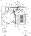
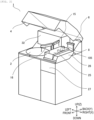
- an automatic analyzer 1 One example of the overall configuration of an automatic analyzer 1 is described with reference to Fig. 1 and Fig. 2 . Assume a leftward-rightward direction of the automatic analyzer 1 as an X axis, a frontward-and-rearward direction of the automatic analyzer 1 as a Y axis and upward-downward direction of the automatic analyzer as a Z axis, and the rightward direction, the rearward direction and the upper direction as the normal directions of the respective axes.
- the automatic analyzer 1 is a device which analyzes a specific component contained in blood, urine or the like provided from a patient.
- a specific component and a marker substance are bonded to each other by an antigen-antibody reaction, and the specific component is subjected to a quantitative analysis or a qualitative analysis using a signal such as an emitted light or absorbed light obtained from the marker substance.
- the automatic analyzer 1 includes a specimen conveyance path 5, an expendable item case 100, a reagent disk 2, an incubator 9, a specimen dispensing unit 6, a reagent dispensing unit 15, a stirring portion 16, a B/F separation portion 30, a detection portion 31, a body cover 4, and a control unit 200.
- a specimen conveyance path 5 an expendable item case 100
- a reagent disk 2 an incubator 9
- a specimen dispensing unit 6 a reagent dispensing unit
- a stirring portion 16 a B/F separation portion 30
- detection portion 31 a body cover 4
- the specimen conveyance path 5 conveys a specimen rack 5a on which a plurality of specimen container each accommodating a specimen are mounted to a position at which a specimen dispensing unit 6 can get access to the specimen.
- the specimen which is accommodated in the specimen container is dispensed to a reaction cell 14 held by the incubator 9 by the specimen dispensing unit 6.
- reaction cells 14 and dispensing tips 10 that are expendable items are accommodated in a state where the reaction cells 14 and the dispensing tips 10 are arranged on a tray 7.
- FIG. 1 illustrates a state where the reaction cells 14 are arranged in a left-side half of the tray 7, and the dispensing tips 10 are arranged in a right-side half of the tray 7.
- the tray 7 on which the reaction cells 14 and the dispensing tips 10 are arranged is put from an expendable item supply port 27 by an operator.
- the dispensing tip 10 is gripped by an expendable item conveyance portion 8, and is transferred from the tray 7 to a tip buffer 11.
- the dispensing tip 10 is mounted on a distal end of a nozzle of the specimen dispensing unit 6, and is used for dispensing the specimen.
- the dispensing chip 10 is exchanged each time the specimen dispensing unit 6 dispenses the specimen for preventing the intrusion of the specimen, and the used dispending tip 10 is discarded to a tip disposal hole 12.
- a reaction cell 14 is gripped by the expendable item conveyance portion 8, is transferred from the tray 7 to the incubator 9, and is used for accommodating a mixed liquid of a specimen and a reagent. Each time a reaction between the specimen and the reagent is performed and an analysis is performed after the reaction, the reaction cell 14 is also exchanged.
- the expendable item case 100 is described later with reference to FIG. 3 , FIG. 4A and FIG. 4B .
- a plurality of reagent container 3 each of which accommodates a reagent is stored in the reagent disk 2.
- the inside of the reagent disk 2 is held at a temperature lower than a room temperature for reducing the degradation of a reagent.
- the reagent disk 2 is covered by a reagent disk cover 21.
- a portion of the reagent disk cover 21 is removed.
- a reagent container loading port 20 is provided for loading and unloading the reagent containers 3.
- a reagent which is accommodated in the reagent container 3 is dispensed to the reaction cell 14 to which a specimen is dispensed by a reagent dispensing unit 15.
- the reagent dispensing unit 15 is washed by a reagent nozzle washing portion 19 after the reagent is dispensed.
- a reagent which is accommodated in the reagent container 3 contains magnetic beads
- the stirring portion 16 having a stirring paddle 17 on a distal end thereof.
- the stirring portion 16 is washed by a paddle washing portion 18 after the reagent is stirred.
- the incubator 9 holds a plurality of reaction cells 14 in each of which a mixed liquid of a specimen and a reagent is held.
- the incubator 9 is held within a range of a target temperature which is a temperature range for causing a reaction of the mixed liquid.
- a reaction liquid which is used in an analysis is produced.
- the reaction cells 14 are arranged along an edge of an outer periphery of the incubator 9. Along with the rotation of the incubator 9, the reaction cells 14 are transferred to positions that the specimen dispensing unit 6 and the reagent dispensing unit 15 can get access to.
- the B/F separation portion 30 includes a conveyance unit 37, a magnetism collecting portion 34, a probe 33, a washing portion 35, and a redispersion portion 36.
- the B/F separation portion 30 separates a reaction liquid into a reaction product (Bound) and a non-reaction substance (Free).
- the conveyance unit 37 conveys the reaction cell 14 from the incubator 9 to the B/F separation portion 30, or conveys the reaction cell 14 from the B/F separation portion 30 to the detection portion 31.
- the magnetism collecting portion 34 collects magnetism of the magnetic beads contained in the reaction liquid so as to separate a reaction product adhering to the magnetic beads from a non-reaction substance.
- the probe 33 aspirates the non-reaction substance separated from the reaction product and discharges a buffer solution which is used for redispersion of the reaction product.
- the washing portion 35 washes the probe 33.
- the redispersion portion 36 disperses the magnetic-collected magnetic beads.
- the reaction cell 14 which accommodates a solution in which the magnetic beads to which the reaction product adheres are redispersed is conveyed to the detection portion 31 by the conveyance unit 37, and is discarded to a cell disposal hole 38 after the processing in the detection portion 31.
- the detection portion 31 includes a light source lamp, a spectrometer, a photomultiplier tube, a photo diode and the like for measuring light emission and absorbance of a solution accommodated in the reaction cell 14 which is conveyed from the B/F separation portion 30.
- the detection portion 31 may also have a temperature control function for holding the solution at a predetermined temperature.
- the detection portion 31 is covered by a detection portion cover 32 which also covers the B/F separation portion 30 and a part of the incubator 9.
- the body cover 4 accommodates the specimen conveyance path 5, the expendable item case 100, the reagent disk 2, the incubator 9, the specimen dispensing unit 6, the reagent dispensing unit 15, the stirring portion 16, the B/F separation portion 30, the detection portion 31 and the like thus preventing the intrusion of dirt or the like into the automatic analyzer 1 and preventing an operator from being brought into contact with these constitutional elements.
- the control unit 200 controls an overall operation of the automatic analyzer 1.
- the control unit 200 may be a dedicated hardware formed of an application specific integrated circuit (ASIC), a field-programmable gate array (FPGA) or the like, or a micro-processing unit (MPU) which executes a software.
- An input device and an output device are connected to the control unit 200. Date necessary for an analysis is inputted via the input device such as a keyboard and a mouse, or a touch panel. A result of the analysis is outputted to the output device such as a liquid crystal display or a touch panel.
- the expendable item case 100 includes the tray 7 described above, an expendable item cover 25, and an enclosing portion 26.
- the reaction cells 14 and the dispensing tips 10 that are expendable items are arranged on the tray 7.
- the expendable item cover 25 covers the tray 7, and includes an open portion through which the expendable item conveyance portion 8 passes on a side surface thereof.
- the open portion is provided to a rear side of the expendable item cover 25.
- the expendable item conveyance portion 8 conveys the reaction cells 14 and the dispensing tips 10 from the tray 7 to the incubator 9 and the chip buffer 11 through the open portion.
- the expendable item cover 25 may be made of a transparent material, for example, an acrylic resin.
- the control unit 200 may perform a residual amount control of the reaction cells 14 or the dispensing tips 10 which are the expendable items.
- the enclosing portion 26 is a box in which the trays 7 are accommodated, and the open portion though which the expendable item conveyance portion 8 gets access to the expendable items on the tray 7 is provided to an upper side of the enclosing portion 26.
- an open portion through which the expendable item conveyance portion 8 passes the enclosing portion 26 may be provided to a side surface of the enclosing portion 26.
- the open portion is provided to a rear side of the enclosing portion 26. As illustrated in FIG. 4A , it is not always necessary that the enclosing portion 26 has a left-and-right symmetrical shape.
- the enclosing portion 26 may have a shape where a portion of the enclosing portion 26 on a side where a drive portion of the expendable item conveyance portion 8 is disposed is larger.
- a fitting portion 105 that protrudes in a horizontal direction may be provided to a rear side of the enclosing portion 26.
- the fitting portion 105 is fitted into a body of the automatic analyzer 1.
- an inclined surface 104 that is high on a side of the open portion is provided to an upper surface of the expendable item cover 25.
- the incubator 9, the tip buffer 11, the specimen dispensing unit 6 and the like are disposed on a rear side of the expendable item cover 25.
- a rear side of the expendable item cover 25 is also referred to as a direction deeper than the open portion.
- An inclination angle SA which is an angle made by the inclined surface 104 and the horizontal surface may be set based on restriction such as an upper limit of a height of the expendable item case 100 or the like. The angle is set to 2 degrees, for example.
- the inclined surface 104 By providing the inclined surface 104, even when the reagent container 3 which is placed on the upper surface of the expendable item cover 25 falls at the time of performing a maintenance operation and a reagent in the reagent container 3 leaks, the leaked reagent does not flow toward the side of the open portion. Further, the inclined surface 104 is inclined such that the reagent does not leak in a direction toward an area where the incubator 9, the tip buffer 11, the specimen dispensing unit 6 and the like are disposed. As a result, accuracy of analysis of a specimen can be maintained.
- a barrier portion 101 which protrudes upward may be provided to an end portion of the expendable item cover 25 at the side of the open portion.
- an eaves portion 107 that protrudes in a horizontal direction may be provided to lower end portions of side surfaces of the expendable item cover 25 to which the open portion is not provided.
- the eaves portion 107 may be fixed to a periphery of the open portion of the enclosing portion 26 by screws 102.
- a convex portion 103 having a surface that faces the eaves portion 107 may be provided to a portion of a periphery of an opening of the enclosing portion 26.
- the convex portion 103 protrudes in an upward direction from an upper surface of the enclosing portion 26, and a stepped portion formed between the convex portion 103 and the upper surface of the enclosing portion 26 is indicated by HA.
- HA stepped portion formed between the convex portion 103 and the upper surface of the enclosing portion 26
- the convex portion 103 it is preferable that the eaves portion 107 protrude more than the convex portion 103 in a horizontal direction.
- a corner portion 106 having an R shape may be provided to roots of the eaves portion 107 and the convex portion 103 for facilitating cleaning.
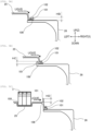
- FIG. 5A illustrates an eaves portion 107 where a barrier portion 101 that protrudes upward is provided to an outer peripheral portion of the eaves portion 107.
- a barrier portion 101 that protrudes upward is provided to an outer peripheral portion of the eaves portion 107.
- a corner portion 106 having an R shape may be provided to a root of the barrier portion 101 for facilitating cleaning. By forming the corner portion 106 into an R shape, a stress concentration can be alleviated so that a mechanical strength of the barrier portion 101 can be increased.
- FIG. 5B illustrates an enclosing portion 26 where a barrier portion 101 that protrudes upward is provided around an opening.
- a barrier portion 101 that protrudes upward is provided around an opening.
- a gap between the barrier portion 101 and the expendable item cover 25 it is possible to prevent the infiltration of the liquid into the expendable item case 100.
- FIG. 5C illustrates an expendable item cover 25 where a barrier portion 101 that protrudes upward is provided to an outer periphery of an upper surface of the expendable item cover 25.
- a barrier portion 101 that protrudes upward is provided to an outer periphery of an upper surface of the expendable item cover 25.
- a hollow 108 into which a reagent container 3 is inserted may be provided to an upper surface of the expendable item cover 25.
- the reagent container 3 By inserting the reagent container 3 into the hollow 108, the reagent container 3 is stably placed on the upper surface of the expendable item cover 25 and hence, falling of the reagent container 3 can be suppressed.
- the hollow 108 is preferably configured such that a length of the hollow 108 in a direction orthogonal to a side surface to which an open portion is provided, that is, the length of the hollow 108 in a longitudinal direction in this embodiment is shorter than a length of a long side of the reagent container 3.
- the reagent container 3 which is inserted into the hollow 108 is placed such that the side surface to which the open portion is provided and a long side of the reagent container 3 are arranged parallel to each other. Accordingly, a falling direction of the reagent container 3 is limited.
- the present invention has been described heretofore.
- the present invention is not limited to the above-mentioned embodiment, and the constitutional elements may be modified without departing from the gist of the present invention.
- the plurality of constitutional elements disclosed in the above-mentioned embodiment may be suitably combined with each other.
- some constitutional elements may be deleted from all constitutional elements described in the embodiment.
Landscapes
- Physics & Mathematics (AREA)
- Health & Medical Sciences (AREA)
- Life Sciences & Earth Sciences (AREA)
- Chemical & Material Sciences (AREA)
- Analytical Chemistry (AREA)
- Biochemistry (AREA)
- General Health & Medical Sciences (AREA)
- General Physics & Mathematics (AREA)
- Immunology (AREA)
- Pathology (AREA)
- Automatic Analysis And Handling Materials Therefor (AREA)
Abstract
Description
- The present invention relates to an automatic analyzer.
- An automatic analyzer is a device which analyzes a specific component contained in a specimen such as blood or urine provided from a patient, and is used in a hospital and a detection agency. A dispensing tip used for dispensing a specimen and a reaction cell used for reaction between a specimen and a reagent are treated as an expendable item that is thrown away for preventing the inclusion of a foreign substance. The dispensing tip is accommodated in a case for expendable items or the like.
-
Patent literature 1 discloses a tip accommodating case which includes: a tip holding plate on which a plurality of dispensing tips are held; a body portion that is a square or rectangular box, the box provided with an opening in which the tip holding plate is fitted on an upper side thereof; and a lid portion that is openable and closable, the lid portion provided with an opening in which the body portion is fitted. - Patent literature:
Japanese Unexamined Patent Application Publication No. 2000-221200 - However, in
patent literature 1, it is necessary to open a lid portion to take out a dispensing tip. Accordingly, to realize automatic conveyance of n expendable item such as the dispensing tip, an opening must be provided to at least one surface out of four surfaces of the lid portion. There may be a case where, on an upper surface of the lid portion where the opening is provided to at least one surface out of four surfaces of the lid portion, a reagent container that is exchanged when an operator of an automatic analyzer performs an expendable item exchanging operation, a container that is filled with a washing liquid and is used during a maintenance operation or the like is placed. In such a case, there is a possibility that the reagent container or the like turns down so that a liquid leaks. When the leaked liquid reaches the dispensing tip, the reaction cell or the like disposed in the case for expendable items, the liquid affects accuracy of analysis of a specimen. - Accordingly, it is an object of the present invention to provide an automatic analyzer capable of maintaining analysis accuracy of a specimen even when a liquid leaks on an expendable item case in which an expendable item is accommodated.
- The present invention that achieves the above-mention object is an automatic analyzer that includes: an analysis unit which analyzes a specimen; an expendable item case which accommodates expendable items including a dispensing tip used for dispensing of the specimen and a reaction cell used for reaction between the specimen and a reagent; a conveyance portion which conveys the expendable items; and a body cover which covers the analysis unit, the expendable item case, and the expendable item conveyance portion. In the automatic analyzer, the expendable item case includes a tray in which the expendable items are arrayed, and an expendable item cover which covers the tray and in which an open portion through which the expendable item conveyance portion passes is provided on a side surface thereof, and a barrier portion protruding upward is provided at an end on a side of the open portion of the expendable item cover.
- According to the present invention, it is possible to provide the automatic analyzer which can maintain accuracy of analysis of a specimen even when a liquid leaks on an expendable item case in which expendable items are accommodated.
-
- [
FIG. 1] FIG. 1 is a plan view illustrating an example of an overall configuration of an automatic analyzer. - [
FIG. 2] FIG. 2 is a perspective view illustrating an example of the external appearance of the automatic analyzer. - [
FIG. 3] FIG. 3 is a side view illustrating an example of the shape of a expendable item cover. - [
FIG. 4A] FIG. 4A is a cross-sectional view taken along a line A-A illustrated inFIG. 3 . - [
FIG. 4B] FIG. 4B is an enlarged view of a dotted portion illustrated inFIG. 4A . - [
FIG. 5A] FIG. 5A is a cross-sectional view illustrating another example of the shape of an eaves portion of the expendable item cover. - [
FIG. 5B] FIG. 5B is a cross-sectional view illustrating an example of the shape of an enclosing portion of an expendable item case. - [
FIG. 5C] FIG. 5C is a cross-sectional view illustrating another example of the shape of the expendable item cover. - Hereinafter, preferred embodiments of an automatic analyzer according to the present invention are described with reference to attached drawings. In the description made hereinafter and the attached drawings, the same symbols are given to constitutional elements having the identical functions and configurations, and the repeated explanation of these constitutional elements are omitted.
- One example of the overall configuration of an
automatic analyzer 1 is described with reference toFig. 1 andFig. 2 . Assume a leftward-rightward direction of theautomatic analyzer 1 as an X axis, a frontward-and-rearward direction of theautomatic analyzer 1 as a Y axis and upward-downward direction of the automatic analyzer as a Z axis, and the rightward direction, the rearward direction and the upper direction as the normal directions of the respective axes. Theautomatic analyzer 1 is a device which analyzes a specific component contained in blood, urine or the like provided from a patient. In an immune analysis method that makes use of an immune reaction, a specific component and a marker substance are bonded to each other by an antigen-antibody reaction, and the specific component is subjected to a quantitative analysis or a qualitative analysis using a signal such as an emitted light or absorbed light obtained from the marker substance. - The
automatic analyzer 1 includes aspecimen conveyance path 5, anexpendable item case 100, areagent disk 2, anincubator 9, aspecimen dispensing unit 6, areagent dispensing unit 15, astirring portion 16, a B/F separation portion 30, adetection portion 31, abody cover 4, and acontrol unit 200. Hereinafter, the respective portions are described. - The
specimen conveyance path 5 conveys aspecimen rack 5a on which a plurality of specimen container each accommodating a specimen are mounted to a position at which aspecimen dispensing unit 6 can get access to the specimen. The specimen which is accommodated in the specimen container is dispensed to areaction cell 14 held by theincubator 9 by thespecimen dispensing unit 6. - In the
expendable item case 100,reaction cells 14 and dispensingtips 10 that are expendable items are accommodated in a state where thereaction cells 14 and thedispensing tips 10 are arranged on atray 7.FIG. 1 illustrates a state where thereaction cells 14 are arranged in a left-side half of thetray 7, and thedispensing tips 10 are arranged in a right-side half of thetray 7. Thetray 7 on which thereaction cells 14 and thedispensing tips 10 are arranged is put from an expendableitem supply port 27 by an operator. The dispensingtip 10 is gripped by an expendableitem conveyance portion 8, and is transferred from thetray 7 to a tip buffer 11. Thereafter, the dispensingtip 10 is mounted on a distal end of a nozzle of thespecimen dispensing unit 6, and is used for dispensing the specimen. The dispensingchip 10 is exchanged each time thespecimen dispensing unit 6 dispenses the specimen for preventing the intrusion of the specimen, and the used dispendingtip 10 is discarded to atip disposal hole 12. Areaction cell 14 is gripped by the expendableitem conveyance portion 8, is transferred from thetray 7 to theincubator 9, and is used for accommodating a mixed liquid of a specimen and a reagent. Each time a reaction between the specimen and the reagent is performed and an analysis is performed after the reaction, thereaction cell 14 is also exchanged. Theexpendable item case 100 is described later with reference toFIG. 3 ,FIG. 4A and FIG. 4B . - A plurality of
reagent container 3 each of which accommodates a reagent is stored in thereagent disk 2. The inside of thereagent disk 2 is held at a temperature lower than a room temperature for reducing the degradation of a reagent. Thereagent disk 2 is covered by areagent disk cover 21. InFIG. 1 , to express an arrangement example of thereagent containers 3, a portion of thereagent disk cover 21 is removed. To thereagent disk cover 21, a reagentcontainer loading port 20 is provided for loading and unloading thereagent containers 3. A reagent which is accommodated in thereagent container 3 is dispensed to thereaction cell 14 to which a specimen is dispensed by areagent dispensing unit 15. Thereagent dispensing unit 15 is washed by a reagentnozzle washing portion 19 after the reagent is dispensed. In a case where a reagent which is accommodated in thereagent container 3 contains magnetic beads, before the reagent is dispensed, the reagent is stirred by the stirringportion 16 having a stirringpaddle 17 on a distal end thereof. The stirringportion 16 is washed by apaddle washing portion 18 after the reagent is stirred. - The
incubator 9 holds a plurality ofreaction cells 14 in each of which a mixed liquid of a specimen and a reagent is held. Theincubator 9 is held within a range of a target temperature which is a temperature range for causing a reaction of the mixed liquid. By causing the reaction of the mixed liquid over a predetermined time within the range of the target temperature in a step of holding thereaction cell 14 in theincubator 9, a reaction liquid which is used in an analysis is produced. In a case where theincubator 9 has a circular shape illustrated inFIG. 1 , thereaction cells 14 are arranged along an edge of an outer periphery of theincubator 9. Along with the rotation of theincubator 9, thereaction cells 14 are transferred to positions that thespecimen dispensing unit 6 and thereagent dispensing unit 15 can get access to. - The B/
F separation portion 30 includes aconveyance unit 37, amagnetism collecting portion 34, aprobe 33, awashing portion 35, and aredispersion portion 36. The B/F separation portion 30 separates a reaction liquid into a reaction product (Bound) and a non-reaction substance (Free). Theconveyance unit 37 conveys thereaction cell 14 from theincubator 9 to the B/F separation portion 30, or conveys thereaction cell 14 from the B/F separation portion 30 to thedetection portion 31. Themagnetism collecting portion 34 collects magnetism of the magnetic beads contained in the reaction liquid so as to separate a reaction product adhering to the magnetic beads from a non-reaction substance. Theprobe 33 aspirates the non-reaction substance separated from the reaction product and discharges a buffer solution which is used for redispersion of the reaction product. Thewashing portion 35 washes theprobe 33. Theredispersion portion 36 disperses the magnetic-collected magnetic beads. Thereaction cell 14 which accommodates a solution in which the magnetic beads to which the reaction product adheres are redispersed is conveyed to thedetection portion 31 by theconveyance unit 37, and is discarded to acell disposal hole 38 after the processing in thedetection portion 31. - The
detection portion 31 includes a light source lamp, a spectrometer, a photomultiplier tube, a photo diode and the like for measuring light emission and absorbance of a solution accommodated in thereaction cell 14 which is conveyed from the B/F separation portion 30. Thedetection portion 31 may also have a temperature control function for holding the solution at a predetermined temperature. Thedetection portion 31 is covered by adetection portion cover 32 which also covers the B/F separation portion 30 and a part of theincubator 9. - The
body cover 4 accommodates thespecimen conveyance path 5, theexpendable item case 100, thereagent disk 2, theincubator 9, thespecimen dispensing unit 6, thereagent dispensing unit 15, the stirringportion 16, the B/F separation portion 30, thedetection portion 31 and the like thus preventing the intrusion of dirt or the like into theautomatic analyzer 1 and preventing an operator from being brought into contact with these constitutional elements. - The
control unit 200 controls an overall operation of theautomatic analyzer 1. Thecontrol unit 200 may be a dedicated hardware formed of an application specific integrated circuit (ASIC), a field-programmable gate array (FPGA) or the like, or a micro-processing unit (MPU) which executes a software. An input device and an output device are connected to thecontrol unit 200. Date necessary for an analysis is inputted via the input device such as a keyboard and a mouse, or a touch panel. A result of the analysis is outputted to the output device such as a liquid crystal display or a touch panel. - One example of the
expendable item case 100 is described with reference toFIG. 3 ,FIG. 4A and FIG. 4B . Theexpendable item case 100 includes thetray 7 described above, anexpendable item cover 25, and an enclosingportion 26. Thereaction cells 14 and the dispensingtips 10 that are expendable items are arranged on thetray 7. - The expendable item cover 25 covers the
tray 7, and includes an open portion through which the expendableitem conveyance portion 8 passes on a side surface thereof. In this embodiment, the open portion is provided to a rear side of theexpendable item cover 25. The expendableitem conveyance portion 8 conveys thereaction cells 14 and the dispensingtips 10 from thetray 7 to theincubator 9 and the chip buffer 11 through the open portion. To allow an operator to check a residual amount of expendable items on thetray 7 by his/he eyes, theexpendable item cover 25 may be made of a transparent material, for example, an acrylic resin. At a timing which an operator charges thetray 7, thecontrol unit 200 may perform a residual amount control of thereaction cells 14 or the dispensingtips 10 which are the expendable items. - The enclosing
portion 26 is a box in which thetrays 7 are accommodated, and the open portion though which the expendableitem conveyance portion 8 gets access to the expendable items on thetray 7 is provided to an upper side of the enclosingportion 26. In the same manner as theexpendable item cover 25, an open portion through which the expendableitem conveyance portion 8 passes the enclosingportion 26 may be provided to a side surface of the enclosingportion 26. In this embodiment, the open portion is provided to a rear side of the enclosingportion 26. As illustrated inFIG. 4A , it is not always necessary that the enclosingportion 26 has a left-and-right symmetrical shape. For example, the enclosingportion 26 may have a shape where a portion of the enclosingportion 26 on a side where a drive portion of the expendableitem conveyance portion 8 is disposed is larger. Further, afitting portion 105 that protrudes in a horizontal direction may be provided to a rear side of the enclosingportion 26. Thefitting portion 105 is fitted into a body of theautomatic analyzer 1. By providing thefitting portion 105, in mounting the enclosingportion 26 on the body of theautomatic analyzer 1, the number of screws for fixing can be reduced. - As illustrated in
FIG. 3 , aninclined surface 104 that is high on a side of the open portion is provided to an upper surface of theexpendable item cover 25. Theincubator 9, the tip buffer 11, thespecimen dispensing unit 6 and the like are disposed on a rear side of theexpendable item cover 25. A rear side of theexpendable item cover 25 is also referred to as a direction deeper than the open portion. An inclination angle SA which is an angle made by theinclined surface 104 and the horizontal surface may be set based on restriction such as an upper limit of a height of theexpendable item case 100 or the like. The angle is set to 2 degrees, for example. By providing theinclined surface 104, even when thereagent container 3 which is placed on the upper surface of the expendable item cover 25 falls at the time of performing a maintenance operation and a reagent in thereagent container 3 leaks, the leaked reagent does not flow toward the side of the open portion. Further, theinclined surface 104 is inclined such that the reagent does not leak in a direction toward an area where theincubator 9, the tip buffer 11, thespecimen dispensing unit 6 and the like are disposed. As a result, accuracy of analysis of a specimen can be maintained. - As illustrated in
FIG. 3 , abarrier portion 101 which protrudes upward may be provided to an end portion of the expendable item cover 25 at the side of the open portion. By providing thebarrier portion 101, even in a case where the inclination angle SA is small so that a liquid that leaks on the expendable item cover 25 flows toward the side of the open portion, the flow of the liquid is stopped by thebarrier portion 101. - As illustrated in
FIG. 3 ,FIG. 4A and FIG. 4B , aneaves portion 107 that protrudes in a horizontal direction may be provided to lower end portions of side surfaces of the expendable item cover 25 to which the open portion is not provided. By providing theeaves portion 107, a mechanical strength of the expendable item cover 25 can be increased. Theeaves portion 107 may be fixed to a periphery of the open portion of the enclosingportion 26 byscrews 102. - A
convex portion 103 having a surface that faces theeaves portion 107 may be provided to a portion of a periphery of an opening of the enclosingportion 26. Theconvex portion 103 protrudes in an upward direction from an upper surface of the enclosingportion 26, and a stepped portion formed between theconvex portion 103 and the upper surface of the enclosingportion 26 is indicated by HA. In a case where theconvex portion 103 is provided, it is preferable that theeaves portion 107 protrude more than theconvex portion 103 in a horizontal direction. By setting a horizontal direction length LA of theeaves portion 107 longer than a width of theconvex portion 103 in a horizontal direction, a leaked liquid flows as indicated by a dotted arrow inFIG. 4B . Accordingly, it is possible to prevent the infiltration of the liquid into theexpendable item case 100 through a gap formed between theeaves portion 107 and theconvex portion 103. Acorner portion 106 having an R shape may be provided to roots of theeaves portion 107 and theconvex portion 103 for facilitating cleaning. - A modification of the
eaves portion 107 is described with reference toFIG. 5A. FIG. 5A illustrates aneaves portion 107 where abarrier portion 101 that protrudes upward is provided to an outer peripheral portion of theeaves portion 107. By providing thebarrier portion 101 having a height HB to an outer periphery of theeaves portion 107, the flow of a liquid that leaks on anexpendable item cover 25 is stopped by thebarrier portion 101 even when the liquid reaches theeaves portion 107. Acorner portion 106 having an R shape may be provided to a root of thebarrier portion 101 for facilitating cleaning. By forming thecorner portion 106 into an R shape, a stress concentration can be alleviated so that a mechanical strength of thebarrier portion 101 can be increased. - A modification of the enclosing
portion 26 is described with reference toFIG. 5B. FIG. 5B illustrates an enclosingportion 26 where abarrier portion 101 that protrudes upward is provided around an opening. By providing thebarrier portion 101 having a height HC around the opening of the enclosingportion 26, the flow of a liquid that leaks on anexpendable item cover 25 is stopped by thebarrier portion 101 even when the liquid reaches an upper surface of the enclosingportion 26 by way of aneaves portion 107. Further, acorner portion 106 having an R shape may be provided to a root of thebarrier portion 101 for facilitating cleaning. It is preferable to form a gap between thebarrier portion 101 and the expendable item cover 25 to an extent that a capillary phenomenon does not occur. By forming such a gap, it is possible to prevent the infiltration of the liquid into theexpendable item case 100. - A modification of the
expendable item cover 25 is described with reference toFIG. 5C. FIG. 5C illustrates an expendable item cover 25 where abarrier portion 101 that protrudes upward is provided to an outer periphery of an upper surface of theexpendable item cover 25. By providing thebarrier portion 101 having a height HD on the outer periphery of the upper surface of theexpendable item cover 25, the flow of a liquid that leaks on theexpendable item cover 25 is stopped by thebarrier portion 101 and stays on the upper surface of theexpendable item cover 25. Acorner portion 106 having an R shape may be provided to a root of thebarrier portion 101 for facilitating cleaning. - A hollow 108 into which a
reagent container 3 is inserted may be provided to an upper surface of theexpendable item cover 25. By inserting thereagent container 3 into the hollow 108, thereagent container 3 is stably placed on the upper surface of theexpendable item cover 25 and hence, falling of thereagent container 3 can be suppressed. Further, the hollow 108 is preferably configured such that a length of the hollow 108 in a direction orthogonal to a side surface to which an open portion is provided, that is, the length of the hollow 108 in a longitudinal direction in this embodiment is shorter than a length of a long side of thereagent container 3. By forming the hollow 108 having such a size, thereagent container 3 which is inserted into the hollow 108 is placed such that the side surface to which the open portion is provided and a long side of thereagent container 3 are arranged parallel to each other. Accordingly, a falling direction of thereagent container 3 is limited. - The embodiment of the present invention has been described heretofore. However, the present invention is not limited to the above-mentioned embodiment, and the constitutional elements may be modified without departing from the gist of the present invention. Further, the plurality of constitutional elements disclosed in the above-mentioned embodiment may be suitably combined with each other. Further, some constitutional elements may be deleted from all constitutional elements described in the embodiment.
-
- 1:
- automatic analyzer
- 2:
- reagent disk
- 3:
- reagent container
- 4:
- body cover
- 5:
- specimen conveyance path
- 5a:
- specimen rack
- 6:
- specimen dispensing unit
- 7:
- tray
- 8:
- expendable item conveyance portion
- 9:
- incubator
- 10:
- dispensing tip
- 11:
- tip buffer
- 12:
- tip disposal hole
- 14:
- reaction cell
- 15:
- reagent dispensing unit
- 16:
- stirring portion
- 17:
- stirring paddle
- 18:
- paddle washing portion
- 19:
- reagent nozzle washing portion
- 20:
- reagent container loading port
- 21:
- reagent disk cover
- 25:
- expendable item cover
- 26:
- enclosing portion
- 27:
- expendable item supply port
- 30:
- B/F separation portion
- 31:
- detection portion
- 32:
- detection portion cover
- 33:
- probe
- 34:
- magnetism collecting portion
- 35:
- washing portion
- 36:
- redispersion portion
- 37:
- conveyance unit
- 38:
- cell disposal hole
- 100:
- expendable item case
- 101:
- barrier portion
- 102:
- screw
- 103:
- convex portion
- 104:
- inclined surface
- 105:
- fitting portion
- 106:
- corner portion
- 107:
- eaves portion
- 108:
- hollow
- 200:
- control unit
Claims (15)
- An automatic analyzer comprising:an analysis unit which analyzes a specimen;an expendable item case which accommodates expendable items including a dispensing tip used for dispensing of the specimen and a reaction cell used for reaction between the specimen and a reagent;an expendable item conveyance portion which conveys the expendable items from the expendable item case; anda body cover which covers the analysis unit, the expendable item case, and the expendable item conveyance portion,wherein the expendable item case includes a tray in which the expendable items are arrayed, and an expendable item cover which covers the tray and in which an open portion through which the expendable item conveyance portion passes is provided on a side surface thereof, andthe expendable item cover includes a barrier portion protruding upward at an end on a side of the open portion.
- The automatic analyzer according to claim 1, wherein
an inclined surface which is high on a side of the open portion is provided on an upper surface of the expendable item cover. - The automatic analyzer according to claim 2, wherein
any one of at least an incubator, a tip buffer, and a specimen dispensing unit is disposed behind the side of the open portion. - The automatic analyzer according to claim 1, wherein
the expendable item cover is provided with an eaves portion protruding in a horizontal direction at a lower end on a side surface on which the open portion is not provided. - The automatic analyzer according to claim 4, whereinthe expendable item case accommodates the tray and further includes an enclosing portion having an opening on an upper side thereof,a convex portion having a surface facing a lower surface of the eaves portion is provided around the opening, andthe eaves portion protrudes beyond the convex portion in a horizontal direction.
- The automatic analyzer according to claim 4, wherein
a barrier portion protruding upward is provided at an outer circumferential portion of the eaves portion. - The automatic analyzer according to claim 6, wherein
a corner portion having an R shape is provided at a root of the eaves portion or a root of the barrier portion. - The automatic analyzer according to claim 1, whereinthe expendable item case accommodates the tray and further includes an enclosing portion having an opening on an upper side thereof, anda barrier portion protruding upward is provided around the opening.
- The automatic analyzer according to claim 1, wherein
the expendable item cover also has the barrier portion at an end on a side surface on which the open portion is not provided. - The automatic analyzer according to claim 1, wherein
the expendable item cover includes a hollow on an upper surface thereof, the hollow being a hollow into which a reagent container accommodating the reagent is inserted. - The automatic analyzer according to claim 10, wherein
the hollow is configured such that a length in a direction orthogonal to a side surface on which the open portion is provided is shorter than a length of a long side of the reagent container. - The automatic analyzer according to claim 1, wherein
the reaction cell is conveyed to the outside of the expendable item case on a side of the open portion. - An automatic analyzer comprising:an analysis unit which analyzes a specimen;an expendable item case which accommodates expendable items including a dispensing tip used for dispensing of the specimen and a reaction cell used for reaction between the specimen and a reagent;an expendable item conveyance portion which conveys the expendable items from the expendable item case; anda body cover which covers the analysis unit, the expendable item case, and the expendable item conveyance portion,wherein the expendable item case includes a tray in which the expendable items are arrayed, and an expendable item cover which covers the tray and in which an open portion through which the expendable item conveyance portion passes is provided on a side surface thereof, andthe expendable item cover is provided with an eaves portion protruding in a horizontal direction at a lower end on a side surface on which the open portion is not provided.
- The automatic analyzer according to claim 13, wherein
an inclined surface which is high on a side of the open portion is provided on an upper surface of the expendable item cover. - The automatic analyzer according to claim 14, wherein
any one of at least an incubator, a tip buffer, and a specimen dispensing unit is disposed behind the side of the open portion.
Applications Claiming Priority (2)
| Application Number | Priority Date | Filing Date | Title |
|---|---|---|---|
| JP2020128176 | 2020-07-29 | ||
| PCT/JP2021/005311 WO2022024425A1 (en) | 2020-07-29 | 2021-02-12 | Automated analysis device |
Publications (3)
| Publication Number | Publication Date |
|---|---|
| EP4191249A1 true EP4191249A1 (en) | 2023-06-07 |
| EP4191249A4 EP4191249A4 (en) | 2024-08-21 |
| EP4191249B1 EP4191249B1 (en) | 2025-05-28 |
Family
ID=80037915
Family Applications (1)
| Application Number | Title | Priority Date | Filing Date |
|---|---|---|---|
| EP21849819.4A Active EP4191249B1 (en) | 2020-07-29 | 2021-02-12 | Automated analysis device |
Country Status (5)
| Country | Link |
|---|---|
| US (1) | US12535493B2 (en) |
| EP (1) | EP4191249B1 (en) |
| JP (1) | JP7374330B2 (en) |
| CN (1) | CN115867809B (en) |
| WO (1) | WO2022024425A1 (en) |
Family Cites Families (15)
| Publication number | Priority date | Publication date | Assignee | Title |
|---|---|---|---|---|
| US5507410A (en) | 1992-03-27 | 1996-04-16 | Abbott Laboratories | Meia cartridge feeder |
| ES2351337T3 (en) * | 1993-09-24 | 2011-02-03 | Abbott Laboratories | METHOD OF SIMULTANEOUSLY MAKING VARIOUS BIOLOGICAL TESTS. |
| JP2000221200A (en) | 1999-01-29 | 2000-08-11 | Assist:Kk | Chip storage case and chip loading method |
| US20020108857A1 (en) | 2000-12-18 | 2002-08-15 | Michael Paschetto | Automated laboratory system and method |
| US7914737B2 (en) * | 2004-07-01 | 2011-03-29 | Roche Molecular Systems, Inc. | Multi-level diagnostic apparatus with a lift system |
| US8087735B1 (en) * | 2007-05-31 | 2012-01-03 | Steelcase Inc. | Free standing furniture kit and method of assembly |
| KR20130029128A (en) * | 2010-07-23 | 2013-03-21 | 베크만 컬터, 인코포레이티드 | Vessel for real time pcr |
| JP6145002B2 (en) | 2013-09-02 | 2017-06-07 | 株式会社日立ハイテクノロジーズ | Automatic analyzer |
| JP6636047B2 (en) * | 2016-01-13 | 2020-01-29 | 株式会社日立ハイテクノロジーズ | Automatic analyzer and control method thereof |
| CN108885221A (en) * | 2016-03-28 | 2018-11-23 | 株式会社日立高新技术 | Automatic analysing apparatus |
| WO2018155049A1 (en) * | 2017-02-22 | 2018-08-30 | 株式会社 日立ハイテクノロジーズ | Automated analyzer |
| CN110799844B (en) * | 2017-07-21 | 2023-09-12 | 株式会社日立高新技术 | automatic analysis device |
| JP6850227B2 (en) * | 2017-09-13 | 2021-03-31 | 株式会社日立ハイテク | Automatic analyzer |
| CN111094994B (en) * | 2017-09-13 | 2023-05-30 | 株式会社日立高新技术 | Automatic analysis device |
| CA3184660A1 (en) * | 2020-05-15 | 2021-11-18 | Meso Scale Technologies, Llc. | Automation compatible removable lids and methods of use |
-
2021
- 2021-02-12 WO PCT/JP2021/005311 patent/WO2022024425A1/en not_active Ceased
- 2021-02-12 EP EP21849819.4A patent/EP4191249B1/en active Active
- 2021-02-12 JP JP2022539998A patent/JP7374330B2/en active Active
- 2021-02-12 US US18/011,956 patent/US12535493B2/en active Active
- 2021-02-12 CN CN202180047551.1A patent/CN115867809B/en active Active
Also Published As
| Publication number | Publication date |
|---|---|
| WO2022024425A1 (en) | 2022-02-03 |
| US12535493B2 (en) | 2026-01-27 |
| US20230408539A1 (en) | 2023-12-21 |
| CN115867809A (en) | 2023-03-28 |
| JPWO2022024425A1 (en) | 2022-02-03 |
| EP4191249B1 (en) | 2025-05-28 |
| EP4191249A4 (en) | 2024-08-21 |
| CN115867809B (en) | 2026-02-10 |
| JP7374330B2 (en) | 2023-11-06 |
Similar Documents
| Publication | Publication Date | Title |
|---|---|---|
| JP6170511B2 (en) | System, apparatus and device for preparing cells | |
| CN103842826B (en) | Automatic analysing apparatus | |
| EP2182370B1 (en) | Sample processing apparatus and cleaning method | |
| EP2916135B1 (en) | Reagent container and automated analyzer | |
| JP2015508177A5 (en) | ||
| EP3508858B1 (en) | Sample measurement method and sample measurement device | |
| US11054433B2 (en) | Automated analyzer and control method for same | |
| JP7157056B2 (en) | Sample analyzer | |
| EP2367013A2 (en) | Sample analyzer | |
| US8926901B2 (en) | Sample analyzer | |
| US12535493B2 (en) | Automatic analyzer | |
| EP3754339B1 (en) | Automatic analysis device | |
| EP2367010A2 (en) | Sample analyzer | |
| JP2000180368A (en) | Chemical analyzer | |
| JP2024082548A (en) | Transport rack, automatic analyzer, and automatic analysis system | |
| CN113711054B (en) | Automatic analysis device | |
| EP4379390A1 (en) | Automatic analysis device, and guidance method used in automatic analysis device | |
| JP6976781B2 (en) | Automatic analyzer | |
| WO2021111916A1 (en) | Automated analyzer | |
| JP2022133527A (en) | Automatic analysis device | |
| JP2025144280A (en) | automatic analyzer | |
| JP2007309742A (en) | Autoanalyzer | |
| JP2023068295A (en) | Detergent bottle and automatic analyzer | |
| HK1201917B (en) | System, apparatuses and devices for pretreating cells |
Legal Events
| Date | Code | Title | Description |
|---|---|---|---|
| STAA | Information on the status of an ep patent application or granted ep patent |
Free format text: STATUS: THE INTERNATIONAL PUBLICATION HAS BEEN MADE |
|
| PUAI | Public reference made under article 153(3) epc to a published international application that has entered the european phase |
Free format text: ORIGINAL CODE: 0009012 |
|
| STAA | Information on the status of an ep patent application or granted ep patent |
Free format text: STATUS: REQUEST FOR EXAMINATION WAS MADE |
|
| 17P | Request for examination filed |
Effective date: 20221223 |
|
| AK | Designated contracting states |
Kind code of ref document: A1 Designated state(s): AL AT BE BG CH CY CZ DE DK EE ES FI FR GB GR HR HU IE IS IT LI LT LU LV MC MK MT NL NO PL PT RO RS SE SI SK SM TR |
|
| DAV | Request for validation of the european patent (deleted) | ||
| DAX | Request for extension of the european patent (deleted) | ||
| A4 | Supplementary search report drawn up and despatched |
Effective date: 20240719 |
|
| RIC1 | Information provided on ipc code assigned before grant |
Ipc: G01N 35/10 20060101ALI20240716BHEP Ipc: G01N 35/04 20060101ALI20240716BHEP Ipc: G01N 35/00 20060101AFI20240716BHEP |
|
| GRAP | Despatch of communication of intention to grant a patent |
Free format text: ORIGINAL CODE: EPIDOSNIGR1 |
|
| STAA | Information on the status of an ep patent application or granted ep patent |
Free format text: STATUS: GRANT OF PATENT IS INTENDED |
|
| INTG | Intention to grant announced |
Effective date: 20250127 |
|
| GRAS | Grant fee paid |
Free format text: ORIGINAL CODE: EPIDOSNIGR3 |
|
| GRAA | (expected) grant |
Free format text: ORIGINAL CODE: 0009210 |
|
| STAA | Information on the status of an ep patent application or granted ep patent |
Free format text: STATUS: THE PATENT HAS BEEN GRANTED |
|
| AK | Designated contracting states |
Kind code of ref document: B1 Designated state(s): AL AT BE BG CH CY CZ DE DK EE ES FI FR GB GR HR HU IE IS IT LI LT LU LV MC MK MT NL NO PL PT RO RS SE SI SK SM TR |
|
| REG | Reference to a national code |
Ref country code: GB Ref legal event code: FG4D |
|
| REG | Reference to a national code |
Ref country code: CH Ref legal event code: EP |
|
| REG | Reference to a national code |
Ref country code: DE Ref legal event code: R096 Ref document number: 602021031514 Country of ref document: DE |
|
| REG | Reference to a national code |
Ref country code: IE Ref legal event code: FG4D |
|
| REG | Reference to a national code |
Ref country code: NL Ref legal event code: MP Effective date: 20250528 |
|
| PG25 | Lapsed in a contracting state [announced via postgrant information from national office to epo] |
Ref country code: ES Free format text: LAPSE BECAUSE OF FAILURE TO SUBMIT A TRANSLATION OF THE DESCRIPTION OR TO PAY THE FEE WITHIN THE PRESCRIBED TIME-LIMIT Effective date: 20250528 Ref country code: FI Free format text: LAPSE BECAUSE OF FAILURE TO SUBMIT A TRANSLATION OF THE DESCRIPTION OR TO PAY THE FEE WITHIN THE PRESCRIBED TIME-LIMIT Effective date: 20250528 |
|
| REG | Reference to a national code |
Ref country code: LT Ref legal event code: MG9D |
|
| PG25 | Lapsed in a contracting state [announced via postgrant information from national office to epo] |
Ref country code: NO Free format text: LAPSE BECAUSE OF FAILURE TO SUBMIT A TRANSLATION OF THE DESCRIPTION OR TO PAY THE FEE WITHIN THE PRESCRIBED TIME-LIMIT Effective date: 20250828 Ref country code: GR Free format text: LAPSE BECAUSE OF FAILURE TO SUBMIT A TRANSLATION OF THE DESCRIPTION OR TO PAY THE FEE WITHIN THE PRESCRIBED TIME-LIMIT Effective date: 20250829 |
|
| PG25 | Lapsed in a contracting state [announced via postgrant information from national office to epo] |
Ref country code: PL Free format text: LAPSE BECAUSE OF FAILURE TO SUBMIT A TRANSLATION OF THE DESCRIPTION OR TO PAY THE FEE WITHIN THE PRESCRIBED TIME-LIMIT Effective date: 20250528 Ref country code: NL Free format text: LAPSE BECAUSE OF FAILURE TO SUBMIT A TRANSLATION OF THE DESCRIPTION OR TO PAY THE FEE WITHIN THE PRESCRIBED TIME-LIMIT Effective date: 20250528 |
|
| PG25 | Lapsed in a contracting state [announced via postgrant information from national office to epo] |
Ref country code: BG Free format text: LAPSE BECAUSE OF FAILURE TO SUBMIT A TRANSLATION OF THE DESCRIPTION OR TO PAY THE FEE WITHIN THE PRESCRIBED TIME-LIMIT Effective date: 20250528 |
|
| PG25 | Lapsed in a contracting state [announced via postgrant information from national office to epo] |
Ref country code: HR Free format text: LAPSE BECAUSE OF FAILURE TO SUBMIT A TRANSLATION OF THE DESCRIPTION OR TO PAY THE FEE WITHIN THE PRESCRIBED TIME-LIMIT Effective date: 20250528 |
|
| PG25 | Lapsed in a contracting state [announced via postgrant information from national office to epo] |
Ref country code: RS Free format text: LAPSE BECAUSE OF FAILURE TO SUBMIT A TRANSLATION OF THE DESCRIPTION OR TO PAY THE FEE WITHIN THE PRESCRIBED TIME-LIMIT Effective date: 20250828 |
|
| PG25 | Lapsed in a contracting state [announced via postgrant information from national office to epo] |
Ref country code: IS Free format text: LAPSE BECAUSE OF FAILURE TO SUBMIT A TRANSLATION OF THE DESCRIPTION OR TO PAY THE FEE WITHIN THE PRESCRIBED TIME-LIMIT Effective date: 20250928 |
|
| PG25 | Lapsed in a contracting state [announced via postgrant information from national office to epo] |
Ref country code: LV Free format text: LAPSE BECAUSE OF FAILURE TO SUBMIT A TRANSLATION OF THE DESCRIPTION OR TO PAY THE FEE WITHIN THE PRESCRIBED TIME-LIMIT Effective date: 20250528 |
|
| REG | Reference to a national code |
Ref country code: AT Ref legal event code: MK05 Ref document number: 1798861 Country of ref document: AT Kind code of ref document: T Effective date: 20250528 |
|
| PG25 | Lapsed in a contracting state [announced via postgrant information from national office to epo] |
Ref country code: DK Free format text: LAPSE BECAUSE OF FAILURE TO SUBMIT A TRANSLATION OF THE DESCRIPTION OR TO PAY THE FEE WITHIN THE PRESCRIBED TIME-LIMIT Effective date: 20250528 Ref country code: AT Free format text: LAPSE BECAUSE OF FAILURE TO SUBMIT A TRANSLATION OF THE DESCRIPTION OR TO PAY THE FEE WITHIN THE PRESCRIBED TIME-LIMIT Effective date: 20250528 Ref country code: SM Free format text: LAPSE BECAUSE OF FAILURE TO SUBMIT A TRANSLATION OF THE DESCRIPTION OR TO PAY THE FEE WITHIN THE PRESCRIBED TIME-LIMIT Effective date: 20250528 |
|
| PG25 | Lapsed in a contracting state [announced via postgrant information from national office to epo] |
Ref country code: CZ Free format text: LAPSE BECAUSE OF FAILURE TO SUBMIT A TRANSLATION OF THE DESCRIPTION OR TO PAY THE FEE WITHIN THE PRESCRIBED TIME-LIMIT Effective date: 20250528 |
|
| PG25 | Lapsed in a contracting state [announced via postgrant information from national office to epo] |
Ref country code: EE Free format text: LAPSE BECAUSE OF FAILURE TO SUBMIT A TRANSLATION OF THE DESCRIPTION OR TO PAY THE FEE WITHIN THE PRESCRIBED TIME-LIMIT Effective date: 20250528 |
|
| PG25 | Lapsed in a contracting state [announced via postgrant information from national office to epo] |
Ref country code: SK Free format text: LAPSE BECAUSE OF FAILURE TO SUBMIT A TRANSLATION OF THE DESCRIPTION OR TO PAY THE FEE WITHIN THE PRESCRIBED TIME-LIMIT Effective date: 20250528 |
|
| PG25 | Lapsed in a contracting state [announced via postgrant information from national office to epo] |
Ref country code: IT Free format text: LAPSE BECAUSE OF FAILURE TO SUBMIT A TRANSLATION OF THE DESCRIPTION OR TO PAY THE FEE WITHIN THE PRESCRIBED TIME-LIMIT Effective date: 20250528 |
|
| REG | Reference to a national code |
Ref country code: DE Ref legal event code: R097 Ref document number: 602021031514 Country of ref document: DE |
|
| PLBE | No opposition filed within time limit |
Free format text: ORIGINAL CODE: 0009261 |
|
| STAA | Information on the status of an ep patent application or granted ep patent |
Free format text: STATUS: NO OPPOSITION FILED WITHIN TIME LIMIT |
|
| REG | Reference to a national code |
Ref country code: CH Ref legal event code: L10 Free format text: ST27 STATUS EVENT CODE: U-0-0-L10-L00 (AS PROVIDED BY THE NATIONAL OFFICE) Effective date: 20260409 |
|
| PGFP | Annual fee paid to national office [announced via postgrant information from national office to epo] |
Ref country code: DE Payment date: 20260223 Year of fee payment: 6 |
|
| PGFP | Annual fee paid to national office [announced via postgrant information from national office to epo] |
Ref country code: FR Payment date: 20260227 Year of fee payment: 6 |
|
| 26N | No opposition filed |
Effective date: 20260303 |
|
| PG25 | Lapsed in a contracting state [announced via postgrant information from national office to epo] |
Ref country code: LT Free format text: LAPSE BECAUSE OF FAILURE TO SUBMIT A TRANSLATION OF THE DESCRIPTION OR TO PAY THE FEE WITHIN THE PRESCRIBED TIME-LIMIT Effective date: 20250528 |
|
| PG25 | Lapsed in a contracting state [announced via postgrant information from national office to epo] |
Ref country code: SE Free format text: LAPSE BECAUSE OF FAILURE TO SUBMIT A TRANSLATION OF THE DESCRIPTION OR TO PAY THE FEE WITHIN THE PRESCRIBED TIME-LIMIT Effective date: 20250528 |