EP4191016A1 - Valve cylinder, impact device and method - Google Patents
Valve cylinder, impact device and method Download PDFInfo
- Publication number
- EP4191016A1 EP4191016A1 EP21212280.8A EP21212280A EP4191016A1 EP 4191016 A1 EP4191016 A1 EP 4191016A1 EP 21212280 A EP21212280 A EP 21212280A EP 4191016 A1 EP4191016 A1 EP 4191016A1
- Authority
- EP
- European Patent Office
- Prior art keywords
- valve cylinder
- groove
- fluid channels
- pressure space
- impact device
- Prior art date
- Legal status (The legal status is an assumption and is not a legal conclusion. Google has not performed a legal analysis and makes no representation as to the accuracy of the status listed.)
- Granted
Links
Images


Classifications
-
- E—FIXED CONSTRUCTIONS
- E21—EARTH OR ROCK DRILLING; MINING
- E21B—EARTH OR ROCK DRILLING; OBTAINING OIL, GAS, WATER, SOLUBLE OR MELTABLE MATERIALS OR A SLURRY OF MINERALS FROM WELLS
- E21B1/00—Percussion drilling
- E21B1/02—Surface drives for drop hammers or percussion drilling, e.g. with a cable
-
- E—FIXED CONSTRUCTIONS
- E21—EARTH OR ROCK DRILLING; MINING
- E21B—EARTH OR ROCK DRILLING; OBTAINING OIL, GAS, WATER, SOLUBLE OR MELTABLE MATERIALS OR A SLURRY OF MINERALS FROM WELLS
- E21B1/00—Percussion drilling
- E21B1/38—Hammer piston type, i.e. in which the tool bit or anvil is hit by an impulse member
-
- B—PERFORMING OPERATIONS; TRANSPORTING
- B25—HAND TOOLS; PORTABLE POWER-DRIVEN TOOLS; MANIPULATORS
- B25D—PERCUSSIVE TOOLS
- B25D9/00—Portable percussive tools with fluid-pressure drive, i.e. driven directly by fluids, e.g. having several percussive tool bits operated simultaneously
- B25D9/06—Means for driving the impulse member
- B25D9/12—Means for driving the impulse member comprising a built-in liquid motor, i.e. the tool being driven by hydraulic pressure
-
- B—PERFORMING OPERATIONS; TRANSPORTING
- B25—HAND TOOLS; PORTABLE POWER-DRIVEN TOOLS; MANIPULATORS
- B25D—PERCUSSIVE TOOLS
- B25D9/00—Portable percussive tools with fluid-pressure drive, i.e. driven directly by fluids, e.g. having several percussive tool bits operated simultaneously
- B25D9/14—Control devices for the reciprocating piston
- B25D9/16—Valve arrangements therefor
- B25D9/20—Valve arrangements therefor involving a tubular-type slide valve
-
- E—FIXED CONSTRUCTIONS
- E21—EARTH OR ROCK DRILLING; MINING
- E21B—EARTH OR ROCK DRILLING; OBTAINING OIL, GAS, WATER, SOLUBLE OR MELTABLE MATERIALS OR A SLURRY OF MINERALS FROM WELLS
- E21B1/00—Percussion drilling
- E21B1/12—Percussion drilling with a reciprocating impulse member
- E21B1/24—Percussion drilling with a reciprocating impulse member the impulse member being a piston driven directly by fluid pressure
- E21B1/26—Percussion drilling with a reciprocating impulse member the impulse member being a piston driven directly by fluid pressure by liquid pressure
-
- B—PERFORMING OPERATIONS; TRANSPORTING
- B25—HAND TOOLS; PORTABLE POWER-DRIVEN TOOLS; MANIPULATORS
- B25D—PERCUSSIVE TOOLS
- B25D2209/00—Details of portable percussive tools with fluid-pressure drive, i.e. driven directly by fluids, e.g. having several percussive tool bits operated simultaneously
- B25D2209/005—Details of portable percussive tools with fluid-pressure drive, i.e. driven directly by fluids, e.g. having several percussive tool bits operated simultaneously having a tubular-slide valve, which is coaxial with the piston
Definitions
- the invention relates to a valve cylinder for a hydraulic impact device of a rock breaking apparatus.
- the invention further relates to an impact device of a rock breaking apparatus and to a method of preventing cavitation in a hydraulic impact device of a rock breaking apparatus.
- rock breaking apparatuses In mines and at other work sites different type of rock breaking apparatuses are used for drilling drill holes to rock surfaces and breaking rock and other hard materials.
- the rock breaking apparatuses are typically hydraulically powered and comprise hydraulic impact devices with reciprocating percussion pistons.
- Working cycle of the percussion piston can be controlled by a sleeve-like control valve which may be pilot controlled.
- the control valve may be mounted inside a control space of a valve cylinder.
- An object of the invention is to provide a novel and improved valve cylinder and an impact device, and a method for preventing cavitation in a hydraulic impact device of a rock breaking apparatus.
- valve cylinder according to the invention is characterized by the characterizing features of the first independent apparatus claim.
- the impact device according to the invention is characterized by the characterizing features of the second independent apparatus claim.
- the method according to the invention is characterized by the characterizing features of the independent method claim.
- valve cylinder of a hydraulic impact device of a rock breaking apparatus is an elongated piece with a central axis.
- the valve cylinder comprises a central opening extending from a front end of the elongated valve cylinder to its rear end.
- a percussion piston of the impact device is mountable through the central opening.
- the pressure spaces are located at an axial distance from each other.
- Several axial pressure fluid channels are arranged to connect the mentioned pressure spaces.
- One of the mentioned pressure spaces is a control pressure space located at the rear end portion of the valve cylinder.
- the control pressure space is configured to receive a sleeve-like control valve for controlling working cycle of the percussion piston.
- the control pressure space is provided with an inner radial groove comprising a bottom surface defining radial extension of the groove in relation to the central opening adjacent the groove.
- the mentioned axial pressure fluid channels pass the radial groove in axial direction without fluid connection with the groove.
- the cross-sectional shape of the bottom of the mentioned radial groove is rotationally non-symmetrical and comprises surfaces at several different distances from the central axis. In other words, there is not just one circumference in the radial groove forming its bottom surface, but instead, there are several different surface configurations defining the groove bottom or bottom line.
- An advantage of the disclosed solution is that the size of the radial groove can be increased when compared to a simple groove with circular bottom surface. And further, the increase in size is possible even though the axial pressure fluid channels limit the usable space for enlarging the groove.
- the bottom surface is formed of several suitably shaped portions which can bypass the axial pressure fluid channels.
- the aim of the disclosed shaping of the groove is to increase fluid volume of the groove and to thereby decrease possible operational situations where cavitation may occur.
- the rock breaking apparatus is a rock drilling machine.
- the rock breaking apparatus is alternatively a breaking hammer.
- valve cylinder is a cartridge mountable inside a basic body of the impact device.
- valve cylinder is a pilot valve cylinder, inside which the sleeve-like control valve is moved towards reverse direction by means of pilot pressure pulses fed through the mentioned axial pressure fluid channels.
- the bottom surface of the radial groove comprises several curved surfaces.
- the bottom of the groove has curved cross-sectional configuration.
- the bottom surface comprises only curved shapes.
- the bottom of the groove comprises surfaces with at least three different radiuses of curvature R1, R2, R3.
- the axial fluid channels of the valve cylinder are evenly spaced around the central opening in the cross-section at the radial groove. Then there are intermediate sections between the axial fluid channels.
- the groove has its minimum radial dimensions at the axial fluid channels and maximum radial dimensions at the mentioned intermediate sections.
- the radial dimensions of the grooves at the intermediate sections are greatest at the middle of the intermediate sections and decrease continuously from the middle towards sections with the axial fluid channels, whereby the shapes of the bottoms are curved at the intermediate sections.
- the shapes of bottoms of the grooves at the mentioned intermediate sections are circular arches.
- the bottom of the groove at the intermediate section may have any other curved shape than the mentioned circular arch. Then radius or curvature may change continuously or gradually, for example.
- number of the axial fluid channels is three.
- the axial fluid channels may be spaced unevenly around the central opening.
- the number of the axial fluid channels may be 2 - 8.
- the groove is made by milling techniques.
- the groove is made by means of a modern CNC lathe by utilizing synchronized turning movement and cutting tool movement.
- a further possibility is to implement a modern computer numerical controlled turning center.
- the groove bottoms at the intermediate sections can be made by means of a rotating side-milling cutter.
- the groove bottoms for the intermediate sections are quick and inexpensive to manufacture.
- the groove bottoms at the intermediate sections can be made by means of a rotating end mill. Then the shape of the bottom can be designed freely. Modern numerically controlled machining centers can realize desired cutting tool paths accurately.
- the radial groove is located at a front end portion of the control pressure space.
- the bottom of the radial groove is provided with at least one transverse fluid channel providing fluid connection between the groove and an outer surface of the valve cylinder.
- the groove serves as a part of a fluid path intended for conveying fluid flows.
- the axial fluid channels are spaced around the central opening whereby the cross-section of the valve cylinder comprises fluid channel sections and intermediate sections between the fluid channel sections.
- the bottom of the radial groove is provided with several transverse fluid channels at each intermediate section. Because of the non-circular shape of the bottom surface of the groove nominal thickness of wall of the valve cylinder at the groove may be smaller at the intermediate sections compared to the fluid channel sections. In other words, the valve cylinder may have varying wall thickness in at the cross section of the groove.
- the disclosed solution relates to an impact device of a rock breaking apparatus.
- the impact device comprises: a body provided with a central space; a percussion cartridge arranged axially inside a rear portion of the mentioned central space and comprising a valve cylinder; a percussion piston passing through the percussion cartridge and being movable in an impact direction towards a front end of the impact device and in a reverse direction towards a rear end of the impact device; a working pressure space provided with hydraulic pressure fluid for moving the percussion piston in the reverse direction; a control pressure space at a rear end of the valve cylinder and being provided with a sleeve-like control valve for controlling hydraulic pressure affecting at the control pressure space and to thereby controlling reciprocating movement of the percussion piston; and wherein the valve cylinder is provided with a pilot pressure space for providing pressure pulses in response to movement of the percussion piston in the impact direction; and the valve cylinder is further provided with several axial fluid channels for connecting the pilot pressure space and the control pressure space. Furthermore, the valve cylinder of the impact is
- the disclosed solution relates to a method of preventing cavitation in a hydraulic impact device of a rock breaking apparatus.
- the method comprises: increasing volume of a hydraulic space between an inner surface of a control pressure space of the impact device and an outer surface of a sleeve-like control valve mounted reciprocatively inside the control pressure space; providing the mentioned inner surface of the control pressure space with a groove at a cross-section where are several transverse fluid channels arranged for feeding hydraulic pressure fluid to and from the control pressure space; and increasing the volume by shaping a bottom of the groove to expand towards an outer surface of the impact device at the mentioned transverse fluid channels whereby there are reduced wall thicknesses only at the transverse fluid channels and the shape of a bottom line of the groove deviates from a circle.
- Figure 1 shows a rock drilling unit 1 intended for drilling holes to a rock surface.
- the rock drilling unit 1 is typically mounted to a drilling boom 2 of a rock drilling rig.
- the drilling unit 1 is provided with a feed beam 3 and a rock drilling machine 4 supported on it.
- a drilling tool 5 is connectable to the drilling machine 4.
- the rock drilling machine 4 may comprise a shank adaptor 6 at a front end of the rock drilling machine 4 for connecting the tool 5.
- At an opposite end of the tool 5 is a drill bit 7.
- the rock drilling machine 4 comprises an impact device 8 for providing the drilling tool 5 with impact pulses for breaking the rock, and a rotating device 9 for rotating R the drilling tool 5 around its longitudinal axis.
- the rock drilling machine 4 further comprises a basic body 10 for mounting the impact device 8, the rotating device 9, and possible other devices and elements needed.
- the rock drilling machine 4 may be moved on the feed beam 3 by means of a feed device 11 in a drilling or feed direction A and in a return direction B.
- the rock drilling machine 4 is hydraulically operable whereby the impact device 8 and the rotating device 9 are connected to a hydraulic system HS.
- the impact device 8 may be in accordance with the solution disclosed in this document and may thereby comprise the disclosed valve cylinder.
- Figure 2 discloses a hydraulic breaking hammer 12 mounted to a boom 13 of an excavator 14 and connected to a hydraulic system HS of the excavator 14.
- the breaking hammer 12 comprises a hydraulic impact device 8 for generating impact pulses to a breaking tool 15 connectable to the breaking hammer 1.
- the breaking tool 15 can move in an impact direction A and a return direction B during the rock breaking.
- the impact device 8 may be in accordance with the solution disclosed in this document and may thereby comprise the disclosed valve cylinder.
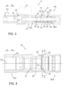
- Figure 3 discloses a rock drilling machine 4 comprising a body 10, an impact device 8, a rotating device 9, a flushing housing 16, an open space 17 for receiving a shank adaptor, and a gear housing 18.
- the flushing housing 16 and gear housing 18 are located at a front end Fe of the body 10, whereas the impact device 8 is located at a rear end Re.
- the shank adapter can be mounted to the open space 17 and its rear end can be connected to rotating elements at the gear housing 18 so that the shank adapter and a drilling tool connectable to the shank adapter can be rotated by means of the rotating device 9.
- Flushing fluid can be fed via the flushing housing 16 to an axial flushing channel of the shank adapter and further to the drilling tool.
- the impact device 8 comprises a percussion piston 19 which is arranged to move in a reciprocating manner in the impact direction A and return direction B. At a front end of the percussion piston 19 is an impact surface 20 which is configured to strike the shank adapter.
- the impact device 8 comprises a percussion cartridge 21 which is arranged axially inside a rear portion Re2 of a central space 22 of the body 10.
- the percussion cartridge 21 comprises a valve cylinder 23 through which the percussion piston 19 passes.
- the impact device 8 comprises a working pressure space 24 provided with hydraulic pressure fluid for moving the percussion piston 19 in the reverse direction B. There is a control pressure space 25 at a rear end Re2 of the valve cylinder 23.
- the control pressure space 25 is provided with a sleeve-like control valve 26 for controlling hydraulic pressure affecting at the control pressure space 25 and to thereby control reciprocating movement of the percussion piston 19.
- the pressure in the control valve space 25 moves the percussion piston 19 in the impact direction because working pressure areas of the percussion piston in the impact direction A are greater therein compared to working pressure areas or the percussion piston at the working pressure space 24 and affecting in the return direction B.
- the working pressure space 24 there may prevail continuous high pressure during the operation, whereas in the control pressure space 25 magnitude of the pressure can be changed by means of the control valve 26 for making the percussion piston 19 to execute the reciprocating movement.
- valve cylinder 23 is provided with a pilot pressure space 27 for providing pressure pulses in response to movement of the percussion piston 19 in the impact direction A.
- the valve cylinder 23 is further provided with several axial fluid channels 28 for connecting the pilot pressure space 27 and the control pressure space 25.
- the pressure pulses generated in the pilot pressure space 27 affect on control surfaces of the control valve 26 and make it to change its control position.
- the control pressure space 25 is provided with an inner radial groove 29 at a front end portion Fe2 of the control pressure space 25.
- Bottom of the radial groove 29 is provided with one or more transverse fluid channels 30 providing fluid connection between the groove 29 and a pressure port 31.
- the purpose of the radial groove 29 is to provide an enlarged space at the transverse fluid channels 30 and to thereby prevent hydraulic cavitation when the control valve 26 executes control measures.
- the impact device 8 disclosed in Figure 3 may be utilized also in a rock breaking hammer. Then there is no rotating device, gearing housing, flushing housing and the shank adapter.
- the percussion piston may be arranged to strike to an impact surface of a breaking tool.
- FIG. 4 discloses a valve cylinder 23 of a percussion cartridge.
- the valve cylinder 23 is an elongated piece with a central axis Ca and comprises a central opening 32 extending from a front end Fe2 of the elongated valve cylinder 23 to its rear end Re2.
- a percussion piston is mountable through the central opening 32.
- Several axial pressure fluid channels 28 connect the mentioned pressure spaces 25, 27.
- a control pressure space 25 is located at the rear end portion Re2 of the valve cylinder 23 and is configured to receive a sleeve-like control valve.
- the control pressure space 25 is provided with an inner radial groove 29 comprising a bottom surface 33 defining radial extension of the groove 29 in relation to the central opening 32 adjacent the groove 29.
- the mentioned axial pressure fluid channels 28 pass the radial groove 29 without being in fluid connection with the groove 29.
- cross-sectional shape of the bottom of the mentioned radial groove 29 is rotationally non-symmetrical and comprises surfaces at several different distances from the central axis. However, this cannot be seen in the cross section in Figure 4 but is shown in Figure 5 .
- the groove 29 is in fluid connection to an outer surface of the valve cylinder 23 by means of one or more transverse fluid channels 30.
- Figure 5 discloses the shape of the bottom surface 33 the groove 29.
- the bottom surface 33 comprises several curved surfaces with different radiuses R1, R2 and R3.
- the axial fluid channels 28 are evenly spaced around the central opening 32 in the cross-section at the radial groove 29 whereby there are intermediate sections 34 between the axial fluid channels 28.
- the groove 29 has its minimum radial dimensions at portions 35 of the axial fluid channels 28 and maximum radial dimensions at the intermediate sections 34.
- the radial dimensions of the groove 29 at the intermediate sections decrease continuously from the middle towards sections 35 with the axial fluid channels 28, whereby the shapes of the bottoms 33 are curved at the intermediate sections 34.
- Number of the axial fluid channels 28 may be three and the shapes of bottoms 33 of the grooves 29 at the intermediate sections 34 may be circular arches. Because of the shape of the bottom 33 of the groove 29, a thickness of a wall Wt1 of the valve cylinder 23 at the groove 29 is greater at the fluid channel sections 35 compared to thickness of a wall Wt2 at the intermediate sections 34.
- the disclosed enlarged volumes of the grooves and the shapes of the bottoms of the grooves may also be implemented in solutions where there is only one axial fluid channel, and further when there are several axial fluid channels which are not evenly space around the open space of the valve cylinder.
Landscapes
- Engineering & Computer Science (AREA)
- Mechanical Engineering (AREA)
- Physics & Mathematics (AREA)
- Fluid Mechanics (AREA)
- Geology (AREA)
- Life Sciences & Earth Sciences (AREA)
- Mining & Mineral Resources (AREA)
- Environmental & Geological Engineering (AREA)
- General Life Sciences & Earth Sciences (AREA)
- Geochemistry & Mineralogy (AREA)
- Earth Drilling (AREA)
- Percussive Tools And Related Accessories (AREA)
- Crushing And Grinding (AREA)
- Actuator (AREA)
Abstract
Description
- The invention relates to a valve cylinder for a hydraulic impact device of a rock breaking apparatus.
- The invention further relates to an impact device of a rock breaking apparatus and to a method of preventing cavitation in a hydraulic impact device of a rock breaking apparatus.
- The field of the invention is defined more specifically in the preambles of the independent claims.
- In mines and at other work sites different type of rock breaking apparatuses are used for drilling drill holes to rock surfaces and breaking rock and other hard materials. The rock breaking apparatuses are typically hydraulically powered and comprise hydraulic impact devices with reciprocating percussion pistons. Working cycle of the percussion piston can be controlled by a sleeve-like control valve which may be pilot controlled. The control valve may be mounted inside a control space of a valve cylinder. The known solutions have shown some disadvantages which especially relate to hydraulic cavitation which is detrimental to durability of the components of the impact device.
- An object of the invention is to provide a novel and improved valve cylinder and an impact device, and a method for preventing cavitation in a hydraulic impact device of a rock breaking apparatus.
- The valve cylinder according to the invention is characterized by the characterizing features of the first independent apparatus claim.
- The impact device according to the invention is characterized by the characterizing features of the second independent apparatus claim.
- The method according to the invention is characterized by the characterizing features of the independent method claim.
- An idea of the disclosed solution is that the valve cylinder of a hydraulic impact device of a rock breaking apparatus is an elongated piece with a central axis. The valve cylinder comprises a central opening extending from a front end of the elongated valve cylinder to its rear end. A percussion piston of the impact device is mountable through the central opening. There are at least two pressure spaces limited by radial surfaces of the central opening. The pressure spaces are located at an axial distance from each other. Several axial pressure fluid channels are arranged to connect the mentioned pressure spaces. One of the mentioned pressure spaces is a control pressure space located at the rear end portion of the valve cylinder. The control pressure space is configured to receive a sleeve-like control valve for controlling working cycle of the percussion piston. The control pressure space is provided with an inner radial groove comprising a bottom surface defining radial extension of the groove in relation to the central opening adjacent the groove. Further, the mentioned axial pressure fluid channels pass the radial groove in axial direction without fluid connection with the groove. The cross-sectional shape of the bottom of the mentioned radial groove is rotationally non-symmetrical and comprises surfaces at several different distances from the central axis. In other words, there is not just one circumference in the radial groove forming its bottom surface, but instead, there are several different surface configurations defining the groove bottom or bottom line.
- An advantage of the disclosed solution is that the size of the radial groove can be increased when compared to a simple groove with circular bottom surface. And further, the increase in size is possible even though the axial pressure fluid channels limit the usable space for enlarging the groove. In the disclosed solution the bottom surface is formed of several suitably shaped portions which can bypass the axial pressure fluid channels.
- According to an embodiment, the aim of the disclosed shaping of the groove is to increase fluid volume of the groove and to thereby decrease possible operational situations where cavitation may occur.
- According to an embodiment, the rock breaking apparatus is a rock drilling machine.
- According to an embodiment, the rock breaking apparatus is alternatively a breaking hammer.
- According to an embodiment, the valve cylinder is a cartridge mountable inside a basic body of the impact device.
- According to an embodiment, the valve cylinder is a pilot valve cylinder, inside which the sleeve-like control valve is moved towards reverse direction by means of pilot pressure pulses fed through the mentioned axial pressure fluid channels.
- According to an embodiment, the bottom surface of the radial groove comprises several curved surfaces. In other words, the bottom of the groove has curved cross-sectional configuration. An advantage of this embodiment is that bottom surface is provided with curved shapes which are hydrodynamically beneficial and do not thereby cause disturbances to hydraulic flows. The curved shapes and surfaces ensure smooth fluid flows.
- According to an embodiment, the bottom surface comprises only curved shapes.
- According to an embodiment, the bottom of the groove comprises surfaces with at least three different radiuses of curvature R1, R2, R3.
- According to an embodiment, the axial fluid channels of the valve cylinder are evenly spaced around the central opening in the cross-section at the radial groove. Then there are intermediate sections between the axial fluid channels. The groove has its minimum radial dimensions at the axial fluid channels and maximum radial dimensions at the mentioned intermediate sections.
- According to an embodiment, in addition to the features of the previous embodiment, the radial dimensions of the grooves at the intermediate sections are greatest at the middle of the intermediate sections and decrease continuously from the middle towards sections with the axial fluid channels, whereby the shapes of the bottoms are curved at the intermediate sections.
- According to an embodiment, the shapes of bottoms of the grooves at the mentioned intermediate sections are circular arches.
- According to an embodiment, the bottom of the groove at the intermediate section may have any other curved shape than the mentioned circular arch. Then radius or curvature may change continuously or gradually, for example.
- According to an embodiment, number of the axial fluid channels is three. In other words, there are three axial fluid channels spaced at 120° orientation relative to each other. At the axial fluid channels are channel sections and between them are intermediate sections. Totally there are three channel sections and three intermediate sections.
- According to an embodiment, in some structures the axial fluid channels may be spaced unevenly around the central opening.
- According to an embodiment, the number of the axial fluid channels may be 2 - 8.
- According to an embodiment, the groove is made by milling techniques.
- According to an embodiment, the groove is made by means of a modern CNC lathe by utilizing synchronized turning movement and cutting tool movement. A further possibility is to implement a modern computer numerical controlled turning center.
- According to an embodiment, the groove bottoms at the intermediate sections can be made by means of a rotating side-milling cutter. The groove bottoms for the intermediate sections are quick and inexpensive to manufacture.
- According to an embodiment, the groove bottoms at the intermediate sections can be made by means of a rotating end mill. Then the shape of the bottom can be designed freely. Modern numerically controlled machining centers can realize desired cutting tool paths accurately.
- According to an embodiment, the radial groove is located at a front end portion of the control pressure space.
- According to an embodiment, the bottom of the radial groove is provided with at least one transverse fluid channel providing fluid connection between the groove and an outer surface of the valve cylinder. In other words, the groove serves as a part of a fluid path intended for conveying fluid flows.
- According to an embodiment, the axial fluid channels are spaced around the central opening whereby the cross-section of the valve cylinder comprises fluid channel sections and intermediate sections between the fluid channel sections. The bottom of the radial groove is provided with several transverse fluid channels at each intermediate section. Because of the non-circular shape of the bottom surface of the groove nominal thickness of wall of the valve cylinder at the groove may be smaller at the intermediate sections compared to the fluid channel sections. In other words, the valve cylinder may have varying wall thickness in at the cross section of the groove.
- According to an embodiment, the disclosed solution relates to an impact device of a rock breaking apparatus. The impact device comprises: a body provided with a central space; a percussion cartridge arranged axially inside a rear portion of the mentioned central space and comprising a valve cylinder; a percussion piston passing through the percussion cartridge and being movable in an impact direction towards a front end of the impact device and in a reverse direction towards a rear end of the impact device; a working pressure space provided with hydraulic pressure fluid for moving the percussion piston in the reverse direction; a control pressure space at a rear end of the valve cylinder and being provided with a sleeve-like control valve for controlling hydraulic pressure affecting at the control pressure space and to thereby controlling reciprocating movement of the percussion piston; and wherein the valve cylinder is provided with a pilot pressure space for providing pressure pulses in response to movement of the percussion piston in the impact direction; and the valve cylinder is further provided with several axial fluid channels for connecting the pilot pressure space and the control pressure space. Furthermore, the valve cylinder of the impact device is in accordance with the embodiments and features disclosed in this application.
- According to an embodiment, the disclosed solution relates to a method of preventing cavitation in a hydraulic impact device of a rock breaking apparatus. The method comprises: increasing volume of a hydraulic space between an inner surface of a control pressure space of the impact device and an outer surface of a sleeve-like control valve mounted reciprocatively inside the control pressure space; providing the mentioned inner surface of the control pressure space with a groove at a cross-section where are several transverse fluid channels arranged for feeding hydraulic pressure fluid to and from the control pressure space; and increasing the volume by shaping a bottom of the groove to expand towards an outer surface of the impact device at the mentioned transverse fluid channels whereby there are reduced wall thicknesses only at the transverse fluid channels and the shape of a bottom line of the groove deviates from a circle.
- The above disclosed embodiments may be combined in order to form suitable solutions having those of the above features that are needed.
- Some embodiments are described in more detail in the accompanying drawings, in which
-
Figure 1 is a schematic side view of a rock drilling unit provided with a hydraulic rock drilling machine, -
Figure 2 is a schematic side view of an excavator provided with a hydraulic breaking hammer, -
Figure 3 is a schematic and cross-sectional side view of a rock drilling machine comprising a hydraulic impact device, -
Figure 4 is a schematic and cross-sectional side view of a valve cylinder, and -
Figure 5 is a schematic view of the valve cylinder ofFigure 4 cut at a cross-section E - E and showing bottom shape of a groove. - For the sake of clarity, the figures show some embodiments of the disclosed solution in a simplified manner. In the figures, like reference numerals identify like elements.
-
Figure 1 shows arock drilling unit 1 intended for drilling holes to a rock surface. Therock drilling unit 1 is typically mounted to adrilling boom 2 of a rock drilling rig. Thedrilling unit 1 is provided with afeed beam 3 and arock drilling machine 4 supported on it. Adrilling tool 5 is connectable to thedrilling machine 4. Therock drilling machine 4 may comprise ashank adaptor 6 at a front end of therock drilling machine 4 for connecting thetool 5. At an opposite end of thetool 5 is adrill bit 7. Therock drilling machine 4 comprises animpact device 8 for providing thedrilling tool 5 with impact pulses for breaking the rock, and arotating device 9 for rotating R thedrilling tool 5 around its longitudinal axis. Therock drilling machine 4 further comprises abasic body 10 for mounting theimpact device 8, therotating device 9, and possible other devices and elements needed. Therock drilling machine 4 may be moved on thefeed beam 3 by means of afeed device 11 in a drilling or feed direction A and in a return direction B. Therock drilling machine 4 is hydraulically operable whereby theimpact device 8 and therotating device 9 are connected to a hydraulic system HS. Further, theimpact device 8 may be in accordance with the solution disclosed in this document and may thereby comprise the disclosed valve cylinder. -
Figure 2 discloses a hydraulic breakinghammer 12 mounted to aboom 13 of anexcavator 14 and connected to a hydraulic system HS of theexcavator 14. The breakinghammer 12 comprises ahydraulic impact device 8 for generating impact pulses to abreaking tool 15 connectable to the breakinghammer 1. The breakingtool 15 can move in an impact direction A and a return direction B during the rock breaking. Theimpact device 8 may be in accordance with the solution disclosed in this document and may thereby comprise the disclosed valve cylinder. -
Figure 3 discloses arock drilling machine 4 comprising abody 10, animpact device 8, arotating device 9, a flushinghousing 16, anopen space 17 for receiving a shank adaptor, and agear housing 18. The flushinghousing 16 andgear housing 18 are located at a front end Fe of thebody 10, whereas theimpact device 8 is located at a rear end Re. The shank adapter can be mounted to theopen space 17 and its rear end can be connected to rotating elements at thegear housing 18 so that the shank adapter and a drilling tool connectable to the shank adapter can be rotated by means of therotating device 9. Flushing fluid can be fed via the flushinghousing 16 to an axial flushing channel of the shank adapter and further to the drilling tool. - The
impact device 8 comprises apercussion piston 19 which is arranged to move in a reciprocating manner in the impact direction A and return direction B. At a front end of thepercussion piston 19 is animpact surface 20 which is configured to strike the shank adapter. Theimpact device 8 comprises apercussion cartridge 21 which is arranged axially inside a rear portion Re2 of acentral space 22 of thebody 10. Thepercussion cartridge 21 comprises avalve cylinder 23 through which thepercussion piston 19 passes. Theimpact device 8 comprises a workingpressure space 24 provided with hydraulic pressure fluid for moving thepercussion piston 19 in the reverse direction B. There is acontrol pressure space 25 at a rear end Re2 of thevalve cylinder 23. Thecontrol pressure space 25 is provided with a sleeve-like control valve 26 for controlling hydraulic pressure affecting at thecontrol pressure space 25 and to thereby control reciprocating movement of thepercussion piston 19. The pressure in thecontrol valve space 25 moves thepercussion piston 19 in the impact direction because working pressure areas of the percussion piston in the impact direction A are greater therein compared to working pressure areas or the percussion piston at the workingpressure space 24 and affecting in the return direction B. In the workingpressure space 24 there may prevail continuous high pressure during the operation, whereas in thecontrol pressure space 25 magnitude of the pressure can be changed by means of thecontrol valve 26 for making thepercussion piston 19 to execute the reciprocating movement. Further, thevalve cylinder 23 is provided with apilot pressure space 27 for providing pressure pulses in response to movement of thepercussion piston 19 in the impact direction A. Thevalve cylinder 23 is further provided with several axialfluid channels 28 for connecting thepilot pressure space 27 and thecontrol pressure space 25. The pressure pulses generated in thepilot pressure space 27 affect on control surfaces of thecontrol valve 26 and make it to change its control position. - The
control pressure space 25 is provided with an innerradial groove 29 at a front end portion Fe2 of thecontrol pressure space 25. Bottom of theradial groove 29 is provided with one or more transversefluid channels 30 providing fluid connection between thegroove 29 and apressure port 31. The purpose of theradial groove 29 is to provide an enlarged space at the transversefluid channels 30 and to thereby prevent hydraulic cavitation when thecontrol valve 26 executes control measures. - The
impact device 8 disclosed inFigure 3 may be utilized also in a rock breaking hammer. Then there is no rotating device, gearing housing, flushing housing and the shank adapter. The percussion piston may be arranged to strike to an impact surface of a breaking tool. -
Figure 4 discloses avalve cylinder 23 of a percussion cartridge. Thevalve cylinder 23 is an elongated piece with a central axis Ca and comprises acentral opening 32 extending from a front end Fe2 of theelongated valve cylinder 23 to its rear end Re2. A percussion piston is mountable through thecentral opening 32. There are twopressure spaces central opening 32 and being located at an axial distance from each other. Several axialpressure fluid channels 28 connect the mentionedpressure spaces control pressure space 25 is located at the rear end portion Re2 of thevalve cylinder 23 and is configured to receive a sleeve-like control valve. Thecontrol pressure space 25 is provided with an innerradial groove 29 comprising abottom surface 33 defining radial extension of thegroove 29 in relation to thecentral opening 32 adjacent thegroove 29. The mentioned axialpressure fluid channels 28 pass theradial groove 29 without being in fluid connection with thegroove 29. Further, cross-sectional shape of the bottom of the mentionedradial groove 29 is rotationally non-symmetrical and comprises surfaces at several different distances from the central axis. However, this cannot be seen in the cross section inFigure 4 but is shown inFigure 5 . Thegroove 29 is in fluid connection to an outer surface of thevalve cylinder 23 by means of one or more transversefluid channels 30. -
Figure 5 discloses the shape of thebottom surface 33 thegroove 29. As can be seen, thebottom surface 33 comprises several curved surfaces with different radiuses R1, R2 and R3. The axialfluid channels 28 are evenly spaced around thecentral opening 32 in the cross-section at theradial groove 29 whereby there areintermediate sections 34 between the axialfluid channels 28. Thegroove 29 has its minimum radial dimensions atportions 35 of the axialfluid channels 28 and maximum radial dimensions at theintermediate sections 34. The radial dimensions of thegroove 29 at the intermediate sections decrease continuously from the middle towardssections 35 with the axialfluid channels 28, whereby the shapes of thebottoms 33 are curved at theintermediate sections 34. Number of the axialfluid channels 28 may be three and the shapes ofbottoms 33 of thegrooves 29 at theintermediate sections 34 may be circular arches. Because of the shape of the bottom 33 of thegroove 29, a thickness of a wall Wt1 of thevalve cylinder 23 at thegroove 29 is greater at thefluid channel sections 35 compared to thickness of a wall Wt2 at theintermediate sections 34. - The disclosed enlarged volumes of the grooves and the shapes of the bottoms of the grooves may also be implemented in solutions where there is only one axial fluid channel, and further when there are several axial fluid channels which are not evenly space around the open space of the valve cylinder.
- The drawings and the related description are only intended to illustrate the idea of the invention. In its details, the invention may vary within the scope of the claims.
Claims (12)
- A valve cylinder (23) for a hydraulic impact device (8) of a rock breaking apparatus (4, 12),
wherein the valve cylinder (23) is an elongated piece with a central axis (Ca) and comprises:a central opening (32) extending from a front end (Fe2) of the elongated valve cylinder (23) to its rear end (Re2), and through which central opening (32) a percussion piston (19) is mountable,at least two pressure spaces (25, 27) limited by radial surfaces of the central opening (32) and being located at an axial distance from each other;several axial pressure fluid channels (28) connecting the mentioned pressure spaces (25, 27);and wherein one of the mentioned pressure spaces (25, 27) is a control pressure space (25) located at the rear end portion (Re2) of the valve cylinder (23) and is configured to receive a sleeve-like control valve (26);and wherein the control pressure space (25) is provided with an inner radial groove (29) comprising a bottom surface (33) defining radial extension of the groove (29) in relation to the central opening (32) adjacent the groove (29) ;and further, the mentioned axial pressure fluid channels (28) pass the radial groove (29) without fluid connection with the groove (29);characterized in thatcross-sectional shape of the bottom of the mentioned radial groove (29) is rotationally non-symmetrical and comprises surfaces at several different distances from the central axis (Ca). - The valve cylinder as claimed in claim 1, characterized in that
the bottom surface (33) of the radial groove (29) comprises several curved surfaces. - The valve cylinder as claimed in claim 1 or 2, characterized in that the valve cylinder (23) further comprises:the axial fluid channels (28) are evenly spaced around the central opening (32) in the cross-section at the radial groove (29) whereby there are intermediate sections (34) between the axial fluid channels (28); andthe groove (29) has its minimum radial dimensions at the axial fluid channels (28) and maximum radial dimensions at the intermediate sections (34).
- The valve cylinder as claimed in claim 3, characterized in that
the radial dimensions of the groove (29) at the intermediate sections (34) are greatest at the middle of the intermediate sections (34) and decrease continuously from the middle towards sections (35) with the axial fluid channels (28), whereby the shapes of the bottoms (33) are curved at the intermediate sections (34). - The valve cylinder as claimed in claim 3 or 4, characterized in that
the shapes of bottoms (33) of the grooves (29) at the intermediate sections (34) are circular arches. - The valve cylinder as claimed in any one of the claims 1 - 5, characterized in that
number of the axial fluid channels (28) is three. - The valve cylinder as claimed in any one of the claims 1 - 6, characterized in that
the groove (29) is made by milling techniques. - The valve cylinder as claimed in any one of the claims 1 - 7, characterized in that
the radial groove (29) is located at a front end portion (Re2) of the control pressure space (25). - The valve cylinder as claimed in any one of the claims 1 - 8, characterized in that
the bottom (33) of the radial groove (29) is provided with at least one transverse fluid channel (30) providing fluid connection between the groove (29) and an outer surface of the valve cylinder (23). - The valve cylinder as claimed in any one of the claims 1 - 9, characterized in thatthe axial fluid channels (28) are spaced around the central opening (32) whereby the cross-section of the valve cylinder (23) comprises fluid channel sections (35) and intermediate sections (34) between the fluid channel sections (35);the bottom (33) of the radial groove (29) is provided with several transverse fluid channels (30) at each intermediate section (34); andthickness of wall (Wt1, Wt2) of the valve cylinder (23) at the groove (29) is smaller at the intermediate sections (34) compared to the fluid channel sections (35).
- An impact device (8) of a rock breaking apparatus (4, 12) comprising:a body (10) provided with a central space;a percussion cartridge (21) arranged axially inside a rear portion of the mentioned central space and comprising a valve cylinder (23);a percussion piston (19) passing through the percussion cartridge (21) and being movable in an impact direction (A) towards a front end (Fe) of the impact device (8) and in a reverse direction (B) towards a rear end (Re) of the impact device (8);a working pressure space (24) provided with hydraulic pressure fluid for moving the percussion piston (19) in the reverse direction (B);a control pressure space (25) at a rear end (Re2) of the valve cylinder (23) and being provided with a sleeve-like control valve (26) for controlling hydraulic pressure affecting at the control pressure space (25) and to thereby controlling reciprocating movement of the percussion piston (19) ;and wherein the valve cylinder (23) is provided with a pilot pressure space (27) for providing pressure pulses in response to movement of the percussion piston (19) in the impact direction (A);and wherein the valve cylinder (23) is further provided with several axial fluid channels (28) for connecting the pilot pressure space (27) and the control pressure space (25) ;characterized in thatthe valve cylinder (23) of the impact device (8) is in accordance with any one of the previous claims 1 - 10.
- A method of preventing cavitation in a hydraulic impact device (8) of a rock breaking apparatus (4, 12);
wherein the method comprises:increasing volume of a hydraulic space between an inner surface of a control pressure space (25) of the impact device (8) and an outer surface of a sleeve-like control valve (26) mounted reciprocatively inside the control pressure space (25);and providing the mentioned inner surface of the control pressure space (25) with a groove (29) at a cross-section where are several transverse fluid channels (30) arranged for feeding hydraulic pressure fluid to and from the control pressure space (25);characterized byincreasing the volume by shaping a bottom (33) of the groove (29) to expand towards an outer surface of the impact device (8) at the mentioned transverse fluid channels (30) whereby the shape of a bottom line of the groove (29) deviates from a circle.
Priority Applications (14)
| Application Number | Priority Date | Filing Date | Title |
|---|---|---|---|
| PL21212280.8T PL4191016T3 (en) | 2021-12-03 | 2021-12-03 | VALVE CYLINDER, IMPACT DEVICE AND METHOD |
| FIEP21212280.8T FI4191016T3 (en) | 2021-12-03 | 2021-12-03 | Valve cylinder, impact device and method |
| EP21212280.8A EP4191016B1 (en) | 2021-12-03 | 2021-12-03 | Valve cylinder, impact device and method |
| PCT/EP2022/084165 WO2023099716A1 (en) | 2021-12-03 | 2022-12-02 | Valve cylinder, impact device and method |
| PE2024001069A PE20241292A1 (en) | 2021-12-03 | 2022-12-02 | VALVE CYLINDER, IMPACT DEVICE AND METHOD |
| CA3236845A CA3236845C (en) | 2021-12-03 | 2022-12-02 | Valve cylinder, impact device and method |
| MX2024006682A MX2024006682A (en) | 2021-12-03 | 2022-12-02 | Valve cylinder, impact device and method. |
| KR1020247015776A KR102775270B1 (en) | 2021-12-03 | 2022-12-02 | Valve cylinder, impact device and method |
| CN202280078757.5A CN118339354B (en) | 2021-12-03 | 2022-12-02 | Valve cylinder, percussion device and method |
| JP2024532949A JP7629579B2 (en) | 2021-12-03 | 2022-12-02 | Valve cylinder, impact device and method |
| US18/714,608 US12404725B2 (en) | 2021-12-03 | 2022-12-02 | Valve cylinder, impact device and method |
| AU2022399949A AU2022399949B2 (en) | 2021-12-03 | 2022-12-02 | Valve cylinder, impact device and method |
| ZA2024/03636A ZA202403636B (en) | 2021-12-03 | 2024-05-10 | Valve cylinder, impact device and method |
| CL2024001631A CL2024001631A1 (en) | 2021-12-03 | 2024-05-31 | Valve cylinder, impact device and method. |
Applications Claiming Priority (1)
| Application Number | Priority Date | Filing Date | Title |
|---|---|---|---|
| EP21212280.8A EP4191016B1 (en) | 2021-12-03 | 2021-12-03 | Valve cylinder, impact device and method |
Publications (2)
| Publication Number | Publication Date |
|---|---|
| EP4191016A1 true EP4191016A1 (en) | 2023-06-07 |
| EP4191016B1 EP4191016B1 (en) | 2024-10-23 |
Family
ID=78821867
Family Applications (1)
| Application Number | Title | Priority Date | Filing Date |
|---|---|---|---|
| EP21212280.8A Active EP4191016B1 (en) | 2021-12-03 | 2021-12-03 | Valve cylinder, impact device and method |
Country Status (13)
| Country | Link |
|---|---|
| US (1) | US12404725B2 (en) |
| EP (1) | EP4191016B1 (en) |
| JP (1) | JP7629579B2 (en) |
| KR (1) | KR102775270B1 (en) |
| CN (1) | CN118339354B (en) |
| AU (1) | AU2022399949B2 (en) |
| CL (1) | CL2024001631A1 (en) |
| FI (1) | FI4191016T3 (en) |
| MX (1) | MX2024006682A (en) |
| PE (1) | PE20241292A1 (en) |
| PL (1) | PL4191016T3 (en) |
| WO (1) | WO2023099716A1 (en) |
| ZA (1) | ZA202403636B (en) |
Families Citing this family (1)
| Publication number | Priority date | Publication date | Assignee | Title |
|---|---|---|---|---|
| CN120845415A (en) * | 2025-09-23 | 2025-10-28 | 湖南康昇智能科技有限公司 | Cylinder and impact device for hydraulic rock drill |
Citations (4)
| Publication number | Priority date | Publication date | Assignee | Title |
|---|---|---|---|---|
| WO2012168558A1 (en) * | 2011-06-07 | 2012-12-13 | Sandvik Mining And Construction Oy | Percussion device of rock breaking device and method for controlling percussion device |
| WO2012168559A1 (en) * | 2011-06-07 | 2012-12-13 | Sandvik Mining And Construction Oy | Percussion device of rock breaking device and method for controlling percussion device |
| EP3100828A1 (en) * | 2014-01-31 | 2016-12-07 | Furukawa Rock Drill Co., Ltd. | Hydraulic hammering device |
| EP3100829A1 (en) * | 2014-01-30 | 2016-12-07 | Furukawa Rock Drill Co., Ltd. | Hydraulic hammering device |
Family Cites Families (9)
| Publication number | Priority date | Publication date | Assignee | Title |
|---|---|---|---|---|
| US3971448A (en) * | 1973-09-04 | 1976-07-27 | The Stanley Works | Breaker construction and valve therefor |
| JPH0713986Y2 (en) * | 1988-02-09 | 1995-04-05 | マツダ株式会社 | Hydraulic impact tool |
| US6155353A (en) * | 1999-07-23 | 2000-12-05 | Ottestad; Jack B. | Impact tool |
| FI119398B (en) * | 2006-12-21 | 2008-10-31 | Sandvik Mining & Constr Oy | The impactor, |
| SE536758C2 (en) * | 2012-11-28 | 2014-07-15 | Atlas Copco Rock Drills Ab | Percussion for a hydraulic rock drill, method for operating a percussion and hydraulic rock drill including percussion |
| EP2873489B1 (en) * | 2013-11-13 | 2018-10-24 | Sandvik Mining and Construction Oy | Impact device and method of dismounting the same |
| EP3023199B1 (en) * | 2014-11-20 | 2019-02-27 | Sandvik Mining and Construction Oy | Percussion piston and method of use |
| JP6757682B2 (en) * | 2017-02-24 | 2020-09-23 | 古河ロックドリル株式会社 | Hydraulic striking device |
| CN111561260B (en) * | 2020-05-21 | 2021-09-10 | 湖南文理学院 | Axial reversing rock drilling device with small structure |
-
2021
- 2021-12-03 EP EP21212280.8A patent/EP4191016B1/en active Active
- 2021-12-03 PL PL21212280.8T patent/PL4191016T3/en unknown
- 2021-12-03 FI FIEP21212280.8T patent/FI4191016T3/en active
-
2022
- 2022-12-02 PE PE2024001069A patent/PE20241292A1/en unknown
- 2022-12-02 CN CN202280078757.5A patent/CN118339354B/en active Active
- 2022-12-02 KR KR1020247015776A patent/KR102775270B1/en active Active
- 2022-12-02 MX MX2024006682A patent/MX2024006682A/en unknown
- 2022-12-02 JP JP2024532949A patent/JP7629579B2/en active Active
- 2022-12-02 US US18/714,608 patent/US12404725B2/en active Active
- 2022-12-02 AU AU2022399949A patent/AU2022399949B2/en active Active
- 2022-12-02 WO PCT/EP2022/084165 patent/WO2023099716A1/en not_active Ceased
-
2024
- 2024-05-10 ZA ZA2024/03636A patent/ZA202403636B/en unknown
- 2024-05-31 CL CL2024001631A patent/CL2024001631A1/en unknown
Patent Citations (4)
| Publication number | Priority date | Publication date | Assignee | Title |
|---|---|---|---|---|
| WO2012168558A1 (en) * | 2011-06-07 | 2012-12-13 | Sandvik Mining And Construction Oy | Percussion device of rock breaking device and method for controlling percussion device |
| WO2012168559A1 (en) * | 2011-06-07 | 2012-12-13 | Sandvik Mining And Construction Oy | Percussion device of rock breaking device and method for controlling percussion device |
| EP3100829A1 (en) * | 2014-01-30 | 2016-12-07 | Furukawa Rock Drill Co., Ltd. | Hydraulic hammering device |
| EP3100828A1 (en) * | 2014-01-31 | 2016-12-07 | Furukawa Rock Drill Co., Ltd. | Hydraulic hammering device |
Also Published As
| Publication number | Publication date |
|---|---|
| EP4191016B1 (en) | 2024-10-23 |
| KR20240089648A (en) | 2024-06-20 |
| CN118339354A (en) | 2024-07-12 |
| FI4191016T3 (en) | 2024-11-25 |
| WO2023099716A1 (en) | 2023-06-08 |
| AU2022399949A1 (en) | 2024-05-30 |
| US12404725B2 (en) | 2025-09-02 |
| PE20241292A1 (en) | 2024-06-21 |
| US20250027368A1 (en) | 2025-01-23 |
| JP7629579B2 (en) | 2025-02-13 |
| JP2024541659A (en) | 2024-11-08 |
| MX2024006682A (en) | 2024-06-19 |
| KR102775270B1 (en) | 2025-02-28 |
| ZA202403636B (en) | 2025-11-26 |
| CN118339354B (en) | 2025-07-29 |
| CA3236845A1 (en) | 2023-06-08 |
| CL2024001631A1 (en) | 2024-11-04 |
| AU2022399949B2 (en) | 2024-10-17 |
| PL4191016T3 (en) | 2025-01-20 |
Similar Documents
| Publication | Publication Date | Title |
|---|---|---|
| US4224846A (en) | Turning boring head with a tool for radial adjustment | |
| CN106694963B (en) | Stepped boring and drilling compound cutter and boring and drilling processing technology thereof | |
| EP3409878A1 (en) | Down the hole drilling machine and method for drilling rock | |
| US12404725B2 (en) | Valve cylinder, impact device and method | |
| CN110998057B (en) | Drill bit with detachable drill bit head | |
| US20200254533A1 (en) | Single-lip deep-hole drill with a chamfered rake face | |
| CA3236845C (en) | Valve cylinder, impact device and method | |
| EP0043291A1 (en) | Improved fluid operated hammer | |
| US4240770A (en) | Boring tool with a floating knife | |
| JP4941356B2 (en) | Drilling tool | |
| EP4261441A1 (en) | Control valve, impact device and method | |
| CN107363305A (en) | A kind of car attacks compound tool | |
| KR100904766B1 (en) | Fine dimension step cutter | |
| RU2820295C1 (en) | Two-cutter device for machining holes | |
| WO2012168558A1 (en) | Percussion device of rock breaking device and method for controlling percussion device | |
| RU2818064C1 (en) | Double cutter hole making device | |
| CN206717096U (en) | A kind of car attacks compound tool | |
| KR20240148251A (en) | Control method of machine tool | |
| SK284422B6 (en) | Drill body with exchangeable cutting plates and internal cooling | |
| HK40018049B (en) | Drill bit with detachable bit head | |
| HK40018049A (en) | Drill bit with detachable bit head | |
| CN107127579A (en) | A kind of compound tool |
Legal Events
| Date | Code | Title | Description |
|---|---|---|---|
| PUAI | Public reference made under article 153(3) epc to a published international application that has entered the european phase |
Free format text: ORIGINAL CODE: 0009012 |
|
| STAA | Information on the status of an ep patent application or granted ep patent |
Free format text: STATUS: THE APPLICATION HAS BEEN PUBLISHED |
|
| AK | Designated contracting states |
Kind code of ref document: A1 Designated state(s): AL AT BE BG CH CY CZ DE DK EE ES FI FR GB GR HR HU IE IS IT LI LT LU LV MC MK MT NL NO PL PT RO RS SE SI SK SM TR |
|
| STAA | Information on the status of an ep patent application or granted ep patent |
Free format text: STATUS: REQUEST FOR EXAMINATION WAS MADE |
|
| 17P | Request for examination filed |
Effective date: 20231207 |
|
| RBV | Designated contracting states (corrected) |
Designated state(s): AL AT BE BG CH CY CZ DE DK EE ES FI FR GB GR HR HU IE IS IT LI LT LU LV MC MK MT NL NO PL PT RO RS SE SI SK SM TR |
|
| GRAP | Despatch of communication of intention to grant a patent |
Free format text: ORIGINAL CODE: EPIDOSNIGR1 |
|
| STAA | Information on the status of an ep patent application or granted ep patent |
Free format text: STATUS: GRANT OF PATENT IS INTENDED |
|
| INTG | Intention to grant announced |
Effective date: 20240704 |
|
| GRAS | Grant fee paid |
Free format text: ORIGINAL CODE: EPIDOSNIGR3 |
|
| GRAA | (expected) grant |
Free format text: ORIGINAL CODE: 0009210 |
|
| STAA | Information on the status of an ep patent application or granted ep patent |
Free format text: STATUS: THE PATENT HAS BEEN GRANTED |
|
| P01 | Opt-out of the competence of the unified patent court (upc) registered |
Free format text: CASE NUMBER: APP_49270/2024 Effective date: 20240829 |
|
| AK | Designated contracting states |
Kind code of ref document: B1 Designated state(s): AL AT BE BG CH CY CZ DE DK EE ES FI FR GB GR HR HU IE IS IT LI LT LU LV MC MK MT NL NO PL PT RO RS SE SI SK SM TR |
|
| REG | Reference to a national code |
Ref country code: GB Ref legal event code: FG4D |
|
| REG | Reference to a national code |
Ref country code: CH Ref legal event code: EP |
|
| REG | Reference to a national code |
Ref country code: DE Ref legal event code: R096 Ref document number: 602021020607 Country of ref document: DE |
|
| REG | Reference to a national code |
Ref country code: IE Ref legal event code: FG4D |
|
| REG | Reference to a national code |
Ref country code: FI Ref legal event code: FGE |
|
| REG | Reference to a national code |
Ref country code: SE Ref legal event code: TRGR |
|
| REG | Reference to a national code |
Ref country code: LT Ref legal event code: MG9D |
|
| REG | Reference to a national code |
Ref country code: NL Ref legal event code: MP Effective date: 20241023 |
|
| REG | Reference to a national code |
Ref country code: AT Ref legal event code: MK05 Ref document number: 1734972 Country of ref document: AT Kind code of ref document: T Effective date: 20241023 |
|
| PG25 | Lapsed in a contracting state [announced via postgrant information from national office to epo] |
Ref country code: NL Free format text: LAPSE BECAUSE OF FAILURE TO SUBMIT A TRANSLATION OF THE DESCRIPTION OR TO PAY THE FEE WITHIN THE PRESCRIBED TIME-LIMIT Effective date: 20241023 |
|
| PG25 | Lapsed in a contracting state [announced via postgrant information from national office to epo] |
Ref country code: NL Free format text: LAPSE BECAUSE OF FAILURE TO SUBMIT A TRANSLATION OF THE DESCRIPTION OR TO PAY THE FEE WITHIN THE PRESCRIBED TIME-LIMIT Effective date: 20241023 |
|
| PG25 | Lapsed in a contracting state [announced via postgrant information from national office to epo] |
Ref country code: HR Free format text: LAPSE BECAUSE OF FAILURE TO SUBMIT A TRANSLATION OF THE DESCRIPTION OR TO PAY THE FEE WITHIN THE PRESCRIBED TIME-LIMIT Effective date: 20241023 Ref country code: PT Free format text: LAPSE BECAUSE OF FAILURE TO SUBMIT A TRANSLATION OF THE DESCRIPTION OR TO PAY THE FEE WITHIN THE PRESCRIBED TIME-LIMIT Effective date: 20250224 Ref country code: IS Free format text: LAPSE BECAUSE OF FAILURE TO SUBMIT A TRANSLATION OF THE DESCRIPTION OR TO PAY THE FEE WITHIN THE PRESCRIBED TIME-LIMIT Effective date: 20250223 |
|
| PG25 | Lapsed in a contracting state [announced via postgrant information from national office to epo] |
Ref country code: BG Free format text: LAPSE BECAUSE OF FAILURE TO SUBMIT A TRANSLATION OF THE DESCRIPTION OR TO PAY THE FEE WITHIN THE PRESCRIBED TIME-LIMIT Effective date: 20241023 |
|
| PG25 | Lapsed in a contracting state [announced via postgrant information from national office to epo] |
Ref country code: ES Free format text: LAPSE BECAUSE OF FAILURE TO SUBMIT A TRANSLATION OF THE DESCRIPTION OR TO PAY THE FEE WITHIN THE PRESCRIBED TIME-LIMIT Effective date: 20241023 |
|
| PG25 | Lapsed in a contracting state [announced via postgrant information from national office to epo] |
Ref country code: NO Free format text: LAPSE BECAUSE OF FAILURE TO SUBMIT A TRANSLATION OF THE DESCRIPTION OR TO PAY THE FEE WITHIN THE PRESCRIBED TIME-LIMIT Effective date: 20250123 |
|
| PG25 | Lapsed in a contracting state [announced via postgrant information from national office to epo] |
Ref country code: GR Free format text: LAPSE BECAUSE OF FAILURE TO SUBMIT A TRANSLATION OF THE DESCRIPTION OR TO PAY THE FEE WITHIN THE PRESCRIBED TIME-LIMIT Effective date: 20250124 Ref country code: LV Free format text: LAPSE BECAUSE OF FAILURE TO SUBMIT A TRANSLATION OF THE DESCRIPTION OR TO PAY THE FEE WITHIN THE PRESCRIBED TIME-LIMIT Effective date: 20241023 Ref country code: AT Free format text: LAPSE BECAUSE OF FAILURE TO SUBMIT A TRANSLATION OF THE DESCRIPTION OR TO PAY THE FEE WITHIN THE PRESCRIBED TIME-LIMIT Effective date: 20241023 |
|
| PG25 | Lapsed in a contracting state [announced via postgrant information from national office to epo] |
Ref country code: RS Free format text: LAPSE BECAUSE OF FAILURE TO SUBMIT A TRANSLATION OF THE DESCRIPTION OR TO PAY THE FEE WITHIN THE PRESCRIBED TIME-LIMIT Effective date: 20250123 |
|
| PG25 | Lapsed in a contracting state [announced via postgrant information from national office to epo] |
Ref country code: SM Free format text: LAPSE BECAUSE OF FAILURE TO SUBMIT A TRANSLATION OF THE DESCRIPTION OR TO PAY THE FEE WITHIN THE PRESCRIBED TIME-LIMIT Effective date: 20241023 |
|
| PG25 | Lapsed in a contracting state [announced via postgrant information from national office to epo] |
Ref country code: MC Free format text: LAPSE BECAUSE OF FAILURE TO SUBMIT A TRANSLATION OF THE DESCRIPTION OR TO PAY THE FEE WITHIN THE PRESCRIBED TIME-LIMIT Effective date: 20241023 |
|
| PG25 | Lapsed in a contracting state [announced via postgrant information from national office to epo] |
Ref country code: DK Free format text: LAPSE BECAUSE OF FAILURE TO SUBMIT A TRANSLATION OF THE DESCRIPTION OR TO PAY THE FEE WITHIN THE PRESCRIBED TIME-LIMIT Effective date: 20241023 |
|
| PG25 | Lapsed in a contracting state [announced via postgrant information from national office to epo] |
Ref country code: EE Free format text: LAPSE BECAUSE OF FAILURE TO SUBMIT A TRANSLATION OF THE DESCRIPTION OR TO PAY THE FEE WITHIN THE PRESCRIBED TIME-LIMIT Effective date: 20241023 |
|
| PG25 | Lapsed in a contracting state [announced via postgrant information from national office to epo] |
Ref country code: RO Free format text: LAPSE BECAUSE OF FAILURE TO SUBMIT A TRANSLATION OF THE DESCRIPTION OR TO PAY THE FEE WITHIN THE PRESCRIBED TIME-LIMIT Effective date: 20241023 |
|
| REG | Reference to a national code |
Ref country code: DE Ref legal event code: R097 Ref document number: 602021020607 Country of ref document: DE |
|
| PG25 | Lapsed in a contracting state [announced via postgrant information from national office to epo] |
Ref country code: SK Free format text: LAPSE BECAUSE OF FAILURE TO SUBMIT A TRANSLATION OF THE DESCRIPTION OR TO PAY THE FEE WITHIN THE PRESCRIBED TIME-LIMIT Effective date: 20241023 |
|
| PG25 | Lapsed in a contracting state [announced via postgrant information from national office to epo] |
Ref country code: CZ Free format text: LAPSE BECAUSE OF FAILURE TO SUBMIT A TRANSLATION OF THE DESCRIPTION OR TO PAY THE FEE WITHIN THE PRESCRIBED TIME-LIMIT Effective date: 20241023 |
|
| PG25 | Lapsed in a contracting state [announced via postgrant information from national office to epo] |
Ref country code: IT Free format text: LAPSE BECAUSE OF FAILURE TO SUBMIT A TRANSLATION OF THE DESCRIPTION OR TO PAY THE FEE WITHIN THE PRESCRIBED TIME-LIMIT Effective date: 20241023 |
|
| REG | Reference to a national code |
Ref country code: CH Ref legal event code: PL |
|
| PG25 | Lapsed in a contracting state [announced via postgrant information from national office to epo] |
Ref country code: LU Free format text: LAPSE BECAUSE OF NON-PAYMENT OF DUE FEES Effective date: 20241203 |
|
| PLBE | No opposition filed within time limit |
Free format text: ORIGINAL CODE: 0009261 |
|
| STAA | Information on the status of an ep patent application or granted ep patent |
Free format text: STATUS: NO OPPOSITION FILED WITHIN TIME LIMIT |
|
| 26N | No opposition filed |
Effective date: 20250724 |
|
| REG | Reference to a national code |
Ref country code: BE Ref legal event code: MM Effective date: 20241231 |
|
| PG25 | Lapsed in a contracting state [announced via postgrant information from national office to epo] |
Ref country code: BE Free format text: LAPSE BECAUSE OF NON-PAYMENT OF DUE FEES Effective date: 20241231 |
|
| PG25 | Lapsed in a contracting state [announced via postgrant information from national office to epo] |
Ref country code: FR Free format text: LAPSE BECAUSE OF NON-PAYMENT OF DUE FEES Effective date: 20241223 |
|
| PG25 | Lapsed in a contracting state [announced via postgrant information from national office to epo] |
Ref country code: CH Free format text: LAPSE BECAUSE OF NON-PAYMENT OF DUE FEES Effective date: 20241231 |
|
| PGFP | Annual fee paid to national office [announced via postgrant information from national office to epo] |
Ref country code: DE Payment date: 20251028 Year of fee payment: 5 |
|
| PGFP | Annual fee paid to national office [announced via postgrant information from national office to epo] |
Ref country code: FI Payment date: 20251211 Year of fee payment: 5 |
|
| PGFP | Annual fee paid to national office [announced via postgrant information from national office to epo] |
Ref country code: TR Payment date: 20251128 Year of fee payment: 5 |
|
| PGFP | Annual fee paid to national office [announced via postgrant information from national office to epo] |
Ref country code: SE Payment date: 20251112 Year of fee payment: 5 |
|
| PGFP | Annual fee paid to national office [announced via postgrant information from national office to epo] |
Ref country code: IE Payment date: 20251111 Year of fee payment: 5 |
|
| PGFP | Annual fee paid to national office [announced via postgrant information from national office to epo] |
Ref country code: PL Payment date: 20251117 Year of fee payment: 5 |
|
| PG25 | Lapsed in a contracting state [announced via postgrant information from national office to epo] |
Ref country code: CY Free format text: LAPSE BECAUSE OF FAILURE TO SUBMIT A TRANSLATION OF THE DESCRIPTION OR TO PAY THE FEE WITHIN THE PRESCRIBED TIME-LIMIT; INVALID AB INITIO Effective date: 20211203 |
|
| PG25 | Lapsed in a contracting state [announced via postgrant information from national office to epo] |
Ref country code: HU Free format text: LAPSE BECAUSE OF FAILURE TO SUBMIT A TRANSLATION OF THE DESCRIPTION OR TO PAY THE FEE WITHIN THE PRESCRIBED TIME-LIMIT; INVALID AB INITIO Effective date: 20211203 |
|
| PG25 | Lapsed in a contracting state [announced via postgrant information from national office to epo] |
Ref country code: SI Free format text: LAPSE BECAUSE OF FAILURE TO SUBMIT A TRANSLATION OF THE DESCRIPTION OR TO PAY THE FEE WITHIN THE PRESCRIBED TIME-LIMIT Effective date: 20241023 |
|
| PG25 | Lapsed in a contracting state [announced via postgrant information from national office to epo] |
Ref country code: LT Free format text: LAPSE BECAUSE OF FAILURE TO SUBMIT A TRANSLATION OF THE DESCRIPTION OR TO PAY THE FEE WITHIN THE PRESCRIBED TIME-LIMIT Effective date: 20241023 |