EP4190966A1 - Garment steamer with heat protection - Google Patents
Garment steamer with heat protection Download PDFInfo
- Publication number
- EP4190966A1 EP4190966A1 EP21212471.3A EP21212471A EP4190966A1 EP 4190966 A1 EP4190966 A1 EP 4190966A1 EP 21212471 A EP21212471 A EP 21212471A EP 4190966 A1 EP4190966 A1 EP 4190966A1
- Authority
- EP
- European Patent Office
- Prior art keywords
- metal layer
- steam generator
- housing
- garment steamer
- air gap
- Prior art date
- Legal status (The legal status is an assumption and is not a legal conclusion. Google has not performed a legal analysis and makes no representation as to the accuracy of the status listed.)
- Withdrawn
Links
- 229910052751 metal Inorganic materials 0.000 claims abstract description 165
- 239000002184 metal Substances 0.000 claims abstract description 165
- 239000004033 plastic Substances 0.000 claims abstract description 11
- 229920003023 plastic Polymers 0.000 claims abstract description 11
- 239000000463 material Substances 0.000 claims abstract description 6
- 239000004411 aluminium Substances 0.000 claims description 8
- 229910052782 aluminium Inorganic materials 0.000 claims description 8
- XAGFODPZIPBFFR-UHFFFAOYSA-N aluminium Chemical compound [Al] XAGFODPZIPBFFR-UHFFFAOYSA-N 0.000 claims description 8
- 229910001092 metal group alloy Inorganic materials 0.000 claims description 7
- 238000009413 insulation Methods 0.000 abstract description 11
- 238000010438 heat treatment Methods 0.000 abstract description 4
- XLYOFNOQVPJJNP-UHFFFAOYSA-N water Substances O XLYOFNOQVPJJNP-UHFFFAOYSA-N 0.000 description 16
- 239000012774 insulation material Substances 0.000 description 5
- 238000010025 steaming Methods 0.000 description 4
- 230000002035 prolonged effect Effects 0.000 description 3
- 238000013459 approach Methods 0.000 description 2
- 238000000034 method Methods 0.000 description 2
- 239000004743 Polypropylene Substances 0.000 description 1
- 230000002745 absorbent Effects 0.000 description 1
- 239000002250 absorbent Substances 0.000 description 1
- 238000010521 absorption reaction Methods 0.000 description 1
- 238000004026 adhesive bonding Methods 0.000 description 1
- 238000009833 condensation Methods 0.000 description 1
- 230000005494 condensation Effects 0.000 description 1
- 230000001419 dependent effect Effects 0.000 description 1
- 230000001627 detrimental effect Effects 0.000 description 1
- 230000005611 electricity Effects 0.000 description 1
- 229920003247 engineering thermoplastic Polymers 0.000 description 1
- 239000006260 foam Substances 0.000 description 1
- 230000017525 heat dissipation Effects 0.000 description 1
- 238000005498 polishing Methods 0.000 description 1
- -1 polypropylene Polymers 0.000 description 1
- 229920001155 polypropylene Polymers 0.000 description 1
- 230000001681 protective effect Effects 0.000 description 1
- 238000002310 reflectometry Methods 0.000 description 1
Images



Classifications
-
- D—TEXTILES; PAPER
- D06—TREATMENT OF TEXTILES OR THE LIKE; LAUNDERING; FLEXIBLE MATERIALS NOT OTHERWISE PROVIDED FOR
- D06F—LAUNDERING, DRYING, IRONING, PRESSING OR FOLDING TEXTILE ARTICLES
- D06F87/00—Apparatus for moistening or otherwise conditioning the article to be ironed or pressed
-
- D—TEXTILES; PAPER
- D06—TREATMENT OF TEXTILES OR THE LIKE; LAUNDERING; FLEXIBLE MATERIALS NOT OTHERWISE PROVIDED FOR
- D06F—LAUNDERING, DRYING, IRONING, PRESSING OR FOLDING TEXTILE ARTICLES
- D06F73/00—Apparatus for smoothing or removing creases from garments or other textile articles by formers, cores, stretchers, or internal frames, with the application of heat or steam
Definitions
- the invention relates to a garment steamer, and in particular to a garment steamer having a steamer head comprising a housing made of plastic material, with a steam generator being contained within the housing.
- the invention may be used in the field of garment care.
- Garment steamers typically comprise a water tank for storing water, a steam generator for generating steam from the water supplied thereto from the water tank, and a treatment plate (also referred to as a soleplate).
- One type of garment steamer is a handheld garment steamer, in which the steam generator, the water tank, and the treatment plate are integrated into a single portable hand unit.
- the compactness of the design intended for better portability may mean that there is less space between the steam generator and the outer housing, such as plastic housing, in which the steam generator is contained.
- This reduction in space in combination with the above-mentioned higher steam generator temperature may risk that the temperature of the external surface of the outer housing becomes unacceptably high, for instance exceeding the allowable temperature increase target of 60 K stated in standard IEC60335-1 clause 11.8 and IEC60335-2-85, clause 11.4, particularly when the garment steamer is used for prolonged duration.
- One conventional solution for reducing the temperature of the external surface of the outer housing is to provide sufficient air space between the steam generator and the outer housing. This means that heat from the steam generator can be transferred to the internal air chamber formed between the steam generator and the outer housing by convection.
- a drawback of such a solution is that a relatively large steamer head containing the steam generator is required, which is detrimental to the portability of the garment steamer.
- the garment steamer according to the invention comprises
- the housing can be regarded as being an outer housing. An external surface of the housing is therefore contactable by a user operating the garment care device.
- the steam generator is contained within, in other words is enclosed by, the housing.
- the at least one metal layer can act as a heat spreader by absorbing heat from the steam generator and spreading it over a surface area of the at least one metal layer.
- the at least one metal layer may therefore assist to minimise or prevent hot spots on the housing caused by the heat generated by the steam generator.
- the at least one metal layer can also have a heat insulation function, since the housing may receive less heat compared to the scenario in which the at least one metal layer is not included in the garment steamer.
- the at least one metal layer can improve user comfort and safety when steaming garments using the garment steamer.
- the at least one metal layer is spaced from the steam generator so to form a first air gap between the steam generator and the at least one metal layer.
- Such a first air gap between the steam generator and the at least one metal layer can act as an insulation layer to assist in lowering the temperature of the housing.
- the first air gap is preferably at least 2 mm. Such a minimum spacing of 2 mm may assist to provide sufficient insulation via the first air gap between the at least one metal layer and the steam generator.
- the at least one metal layer is spaced from the housing to form a second air gap between the at least one metal layer and the housing.
- Such a second air gap between the metal layer(s) and the housing can act as an insulation layer to assist in lowering the temperature of the housing.
- the second air gap is preferably at least 0.5 mm. Such a minimum spacing of 0.5 mm may assist to provide sufficient insulation via the second air gap between the at least one metal layer and the housing.
- the first air gap is preferably wider than the second air gap. This may assist to manage heat transfer from the steam generator to the housing such as to minimise hot spots on the housing.
- the at least one metal layer comprises a first metal layer extending over a top part of the steam generator, and a second metal layer extending over a bottom part of the steam generator.
- the top part of the steam generator corresponds to a cover of the steam generator.
- the first metal layer and the second metal layer each have a thickness being at least 0.2 mm.
- Such a minimum thickness may assist each of the metal layers to spread the heat generated by the steam generator, whilst also ensuring that each of the metal layers is sufficiently rigid and robust.
- the first metal layer is separate from the second metal layer.
- the first metal layer being separate from, in other words not connected to, the second metal layer means that the first and second metal layers do not form an enclosure around the steam generator. In other words, the first and second metal layers do not form a closed sheath or hollow shell around the steam generator.
- the first metal layer being separate from the second metal layer may assist with dissipating the heat of the steam generator within the steamer head.
- An outer periphery of the first metal layer is preferably spaced apart from an opposing outer periphery of the second metal layer by a distance with a value in the range [1;2] cm.
- Each of the at least one metal layer can be formed of a metal or metal alloy.
- the at least one metal layer is made of aluminium.
- the relatively high thermal conductivity of aluminium can make for enhanced heat spreading.
- the at least one metal layer comprises a polished reflective surface, with the polished reflective surface facing the steam generator.
- Such a polished reflective surface can assist to reflect heat back towards the steam generator, so away from the housing.
- the at least one metal layer is fastened to the housing at discrete fastening points.
- Such discrete fastening points may assist to minimise direct heat transfer from the at least one metal layer to the housing.
- the steam generator is preferably made of casted metal alloy.
- the garment steamer is a handheld garment steamer.
- the steam generator for example, the steam generator, a water tank for storing water for supplying to the steam generator, and a treatment plate in which at least one steam outlet is provided for releasing the steam are integrated into a single portable hand unit when the garment steamer is such a handheld garment steamer.
- the at least one metal layer can be particularly advantageous when the garment steamer is a handheld garment steamer because the at least one metal layer can provide a way of minimising temperature increases of the housing while retaining a compact steamer head design which enhances portability.
- Fig.1 depicts a garment steamer 100 according to an example.
- the garment steamer 100 has a steamer head comprising a housing H.
- the garment steamer 100 comprises a steam generator 106 for generating steam.
- the steam generator 106 is contained within the housing H.
- the steam generator 106 is contained within. In other words, the steam generator 106 is enclosed by the housing H.
- the housing H can be regarded as being an outer housing. An external surface of the housing H is therefore contactable by a user operating the garment care device 100.
- the housing H is made of plastic material. Such a plastic housing H may assist the steamer head to be relatively lightweight, and thus enhance the manoeuvrability of the garment steamer 100.
- the housing H is made of an engineering thermoplastic, such as polypropylene.
- the housing H comprises a first housing part 102 and a second housing part 104.
- the steam generator 106 is housed between the first housing part 102 and the second housing part 104.
- the steam generator 106 can have any suitable design. In some embodiments, such as that depicted in Fig.1 , the steam generator 106 comprises a top part 108 and a bottom part 110.
- the top part 108 is, for example, a cover of the steam generator 106.
- the cover defined by the top part 108 can cover the bottom part 110 of the steam generator 106.
- a recess is defined in the bottom part 110, and a steam chamber 112 is provided by the cover closing the recess defined in the bottom part 110.
- the steam generator 106 and in particular the top part 108 and the bottom part 110, can be made of any suitable material, such as a metal or metal alloy.
- the steam generator 106 is (at least partly) made of casted metal alloy.
- At least the bottom part 110 of the steam generator 106 is casted in a metal alloy.
- the garment steamer 100 comprises at least one metal layer 114, 116 arranged between the steam generator 106 and the housing H.
- the at least one metal layer 114, 116 can act as a heat spreader by absorbing heat from the steam generator 106 and spreading it over a surface area of the at least one metal layer 114, 116.
- the at least one metal layer 114, 116 may therefore assist to minimise or prevent hot spots on the housing H caused by the heat generated by the steam generator 106.
- the at least one metal layer 114, 116 can assist to lower the maximum temperature on the external surface of the housing H by spreading heat from the steam generator 106 across the at least one metal layer 114, 116.
- the maximum temperature of the housing H may be lowered as a result of the inclusion of the metal layer(s) 114, 116 when the garment care device 100 reaches thermal equilibrium.
- the at least one metal layer 114, 116 can also have a heat insulation function, since the plastic housing H may receive less heat compared to the scenario (not shown) in which the at least one metal layer is not included in the garment steamer.
- the at least one metal layer 114, 116 can improve user comfort and safety when steaming garments using the garment steamer 100.
- the housing H, the steam generator 106, and the at least one metal layer 114, 116 are configured such that the housing H of the steamer head fulfils the temperature rise requirement of 60 K maximum, as stated in standard IEC60335-1 clause 11.8 and IEC60335-2-85, clause 11.4.
- Each of the at least one metal layer 114, 116 can be formed of a metal or metal alloy.
- the at least one metal layer 114, 116 is made of aluminium.
- the relatively high thermal conductivity of aluminium can make for enhanced heat spreading.
- the shape of the at least one metal layer 114, 116 is not particularly limited, and various shapes for the metal layer(s) 114, 116 can be contemplated provided that the metal layer(s) 114, 116 provides or provide a region of heat spreading and/or shielding in between the steam generator 106 and the housing H.
- the at least one metal layer 114, 116 has a shape which follows at least part of an outer profile of the steam generator 106, and/or a shape which follows at least part of the profile of the housing. This may assist to enhance the compactness of the garment steamer 100.
- each of the at least one metal layer 114, 116 has a curved shape whose curvature follows at least part of the outer profile of the steam generator 106, and/or a curvature which follows at least part of the profile of the housing.
- the at least one metal layer 114, 116 preferably comprises a first metal layer 114 extending over the top part 108 of the steam generator 106, and a second metal layer 116 extending over the bottom part 110 of the steam generator 106.
- the first metal layer 114 faces the top part 108 of the steam generator 106
- the second metal layer 116 faces the bottom part 110 of the steam generator 106.
- An example of this is shown in Figs.1 and 2 .
- the first metal layer 114 has a shape which follows an outer profile of the top part 108 of the steam generator 106.
- the second metal layer 116 has a shape which follows an outer profile of the bottom part 110 of the steam generator 106.
- the at least one metal layer 114, 116 comprises the first metal layer 114 and the second metal layer 116
- these metal layers 114, 116 are preferably separate from each other. In other words, the first metal layer (114) and the second metal layer (116) do not contact with each other.
- the first metal layer 114 being separate from, in other words not connected to, the second metal layer 116, means that the first and second metal layers 114, 116 do not form an enclosure around the steam generator 106. In other words, the first and second metal layers 114, 116 do not form a closed sheath or hollow shell around the steam generator 106.
- the first metal layer 114 being separate from the second metal layer 116 may assist with dissipating the heat of the steam generator 106 within the steamer head.
- an outer periphery OP1 of the first metal layer 114 is preferably spaced apart from an opposing outer periphery OP2 of the second metal layer 116 by a distance D with a value in the range [1;2] cm.
- the distance D being in this [1;2] cm range can assist to balance sufficient heat dissipation via the spacing between the first metal layer 114 and the second metal layer 116, with sufficient coverage of the steam generator 106 by the first metal layer 114 and the second metal layer 116 for heat spreading and heat shielding purposes.
- the at least one metal layer 114, 116 has a thickness being at least 0.2 mm.
- the first metal layer 114 and the second metal layer 116 preferably each have a thickness being at least 0.2 mm.
- Such a minimum thickness may assist the metal layer(s) 114, 116 to spread the heat generated by the steam generator 106, whilst also ensuring that each of the at least one metal layer 114, 116 is sufficiently rigid and robust.
- each of the at least one metal layer 114, 116 is made of aluminium and has a thickness being at least 0.2 mm.
- This combination may provide particularly effective heat spreading and shielding to lower the maximum temperature on the external surface of the housing H, for example such that the housing H fulfils the temperature rise requirement of 60 K maximum, as stated in standard IEC60335-1 clause 11.8 and IEC60335-2-85, clause 11.4.
- the at least one metal layer 114, 116 is spaced from the steam generator 106 so to form a first air gap 118 between the steam generator 106 and the at least one metal layer 114, 116.
- An example of this is shown in Fig.4 .
- Such a first air gap 118 between the steam generator 106 and the at least one metal layer 114, 116 can act as an insulation layer to assist in lowering the temperature of the housing H.
- the first air gap 118 is preferably at least 2 mm. Such a minimum spacing of 2 mm may assist to provide sufficient insulation via the first air gap 118 between the at least one metal layer 114, 116 and the steam generator 106.
- the first air gap 118 does not necessarily have a constant value all around the steam generator.
- the first air gap 118 can be present between the top part 108 of the steam generator 106 and the first metal layer 114, and/or between the bottom part 110 of the steam generator 106 and the second metal layer 116.
- the first air gap 118 is present between the top part 108 of the steam generator 106 and the first metal layer 114, and between the bottom part 110 of the steam generator 106 and the second metal layer 116.
- the at least one metal layer 114, 116 is preferably spaced from the housing H to form a second air gap 120 between the at least one metal layer 114, 116 and the housing H.
- Such a second air gap 120 between the at least one metal layer 114, 116 and the housing H can act as an insulation layer to assist in lowering the temperature of the housing H.
- the second air gap 120 is preferably at least 0.5 mm. Such a minimum spacing of 0.5 mm may assist to provide sufficient insulation via the second air gap between the at least one metal layer 114, 116 and the housing H.
- the second air gap 120 does not necessarily have a constant value all around the steam generator.
- the second air gap 120 can be present between the housing H and the first metal layer 114, and/or between the housing H and the second metal layer 116.
- the second air gap 120 is present between the first housing part 102 and the first metal layer 114, and between the second housing part 104 and the second metal layer 116.
- the first air gap 118 is preferably wider than the second air gap 120. This may assist to manage heat transfer from the steam generator 106 to the housing H such as to minimise hot spots on the housing H.
- the at least one metal layer 114, 116 comprises a polished reflective surface 122, 124, with the polished reflective surface 122, 124 facing the steam generator 106.
- a smooth shiny surface is a good reflector of light and radiant heat. Polishing is a mean to achieve the shiny/glossy surface.
- Figs.6 and 7 show the location (but do not illustrate the reflectivity) of the polished reflective surface 122, 124.
- Such a reflective surface 122, 124 in other words shiny gloss surface, can assist to reflect heat back towards the steam generator 106, so away from the housing H.
- the first metal layer 114 can include a first reflective surface 122 facing the steam generator 106
- the second metal layer 116 can include a second reflective surface 124 facing the steam generator 106.
- the steam generator-facing surface of the second metal layer 116 comprises a recessed portion RP which is recessed relative to neighbouring regions of the surface.
- a recessed portion RP may be provided to, for instance, accommodate a fuse and/or thermostat 125, for controlling the steam generator 106.
- the above-described polished reflective surface 124 is also present in the recessed portion RP.
- the at least one metal layer 114, 116 is fastened to the housing H at discrete fastening points 126A, 126B, 126C, 128A, 128B.
- Such discrete fastening points 126A, 126B, 126C, 128A, 128B may assist to minimise direct heat transfer from the at least one metal layer 114, 116 to the housing H.
- Any suitable fastening/locking principle can be used to fasten the at least one metal layer 114, 116 to the housing H, such as screw fastener(s) 130, 132A, 132B, interlock catch(es) 126A, 126B, interlock heat staking and/or gluing.
- the fastening of the second metal layer 116 to the second housing part 104 is achieved via interlock catches 126A, 126B, such as interlock plastic catches 126A, 126B, and a screw fastener 130, as best shown in Figs.1 , 5 and 6 .
- this minimum thickness can be advantageously combined with the fastening of the at least one metal layer 114, 116 to the housing H comprising one or more interlock catches 126A, 126B, such as interlock plastic catches 126A, 126B.
- the second metal layer 116 is fastened to the second housing part 104 via interlock catches 126A, 126B and is made of aluminium having a thickness of at least 0.2 mm.
- the fastening of the first metal layer 114 to the first housing part 102 is achieved via screw fasteners 132A, 132B, as best shown in Figs.1 and 4 .
- the above-described one or more interlock plastic catches can be alternatively or additionally used to fasten the first metal layer to the first housing part (not shown).
- the at least one metal layer 114, 116 is preferably not mounted to the steam generator 106. Hence heat may not be directly transferred from the steam generator 106 to the metal layer(s) 114, 116 by conduction. This, in turn, can enable various fastening/locking principles, such as the above-described interlock catch(es) 126A, 126B, to be used for fastening the at least one metal layer 114, 116 to the housing H.
- interlock catch(es) 126A, 126B can, for instance, be provided at the base of one or more of the posts 134A-134B-134C-134D-134E-134F-134G-134H-134I included in the first housing part 102 and the second housing part 104 in which threaded holes are provided for fastening the housing parts 102, 104 to each other and/or to other components of the steamer head using screw fasteners (not visible).
- a locking surface 136 can be defined as the area over which the respective metal layer 114, 116 contacts the housing H at one fastening point 126A, 126B, 126C, 128A, 128B.
- the locking surface 136 is preferably minimised in order to minimise direct heat conduction from the metal layer 114, 116 to the housing H.
- the locking surface 136 is restricted to at most 80 mm 2 . This upper limit may, for example, correspond to a circular locking surface whose diameter is about 10 mm.
- a gap between the metal layer(s) and the housing except at the mounting points and/or some discrete point for better support of the metal layer(s).
- Total contact area between the metal layer and the housing should not be more than 25% of the surface area of metal layer facing the housing.
- the garment steamer 100 is preferably a handheld garment steamer 100.
- the steam generator 106 a water tank 138 for storing water for supplying to the steam generator 106, and a treatment plate 140 in which at least one steam outlet 142 is provided for releasing the steam can be integrated into a single portable hand unit when the garment steamer 100 is such a handheld garment steamer 100.
- the steam generator comprises a heating element 150 for heating the steam generator to temperature above 100 degree Celsius for generating steam with water supplied by the water tank, and the heating element is being controlled by suitable control means, for example a thermostat.
- the at least one metal layer 114, 116 can be particularly advantageous when the garment steamer 100 is a handheld garment steamer 100 because the at least one metal layer 114, 116 can provide a way of minimising temperature increases of the housing H while retaining a compact steamer head design which enhances portability.
- the steamer head comprises a mounting member 143 arranged to secure the treatment plate 140 to the housing H.
- the garment steamer 100 preferably comprises a handle 144 for holding the garment steamer 100, with the steamer head being arranged at an end of the handle 144.
- the handle 144 includes the water tank, 138.
- the garment steamer 100 can be used to steam garments once, for instance, the garment steamer 100 is connected to a mains supply of electricity via a power cord 146.
- the power cord 146 connects to the handle 144 via a power cord grommet 148.
Landscapes
- Engineering & Computer Science (AREA)
- Textile Engineering (AREA)
- Cookers (AREA)
- Irons (AREA)
- Thermal Insulation (AREA)
Abstract
The invention relates to a garment steamer (100) comprising a steamer head. The steamer head comprises a housing made of plastic material (H). The garment steamer also comprises a steam generator (106) for generating steam. The steam generator is contained within the housing. At least one metal layer (114, 116) is arranged between the steam generator and the housing for heating spreading and heat insulation purposes.
Description
- The invention relates to a garment steamer, and in particular to a garment steamer having a steamer head comprising a housing made of plastic material, with a steam generator being contained within the housing.
- The invention may be used in the field of garment care.
- Various types of garment steamer are known for steaming garments to remove creases through the use of heat and moisture provided by steam. Garment steamers typically comprise a water tank for storing water, a steam generator for generating steam from the water supplied thereto from the water tank, and a treatment plate (also referred to as a soleplate).
- One type of garment steamer is a handheld garment steamer, in which the steam generator, the water tank, and the treatment plate are integrated into a single portable hand unit.
- Over the years, the power rating of garment steamers, and in particular handheld garment steamers, has increased in order to increase the amount of steam generated and to improve condensation performance so as to minimise water spitting during steaming. With higher power ratings, the steam generator temperature tends to increase.
- Moreover, in the case of handheld garment steamers the compactness of the design intended for better portability may mean that there is less space between the steam generator and the outer housing, such as plastic housing, in which the steam generator is contained. This reduction in space in combination with the above-mentioned higher steam generator temperature may risk that the temperature of the external surface of the outer housing becomes unacceptably high, for instance exceeding the allowable temperature increase target of 60 K stated in standard IEC60335-1 clause 11.8 and IEC60335-2-85, clause 11.4, particularly when the garment steamer is used for prolonged duration.
- One conventional solution for reducing the temperature of the external surface of the outer housing is to provide sufficient air space between the steam generator and the outer housing. This means that heat from the steam generator can be transferred to the internal air chamber formed between the steam generator and the outer housing by convection. However, a drawback of such a solution is that a relatively large steamer head containing the steam generator is required, which is detrimental to the portability of the garment steamer.
- Another possible solution has been used which involves arranging insulation material, for example sponge, foam, etc., onto the steam generator. However, this solution can typically only be implemented on one side of the steam generator because the other side tends to be fully occupied by temperature control components, such as a thermostat and fuse. A further drawback of this solution is that the insulation material can often retain water due to its moisture absorbent properties. Over a prolonged period of use of the garment steamer, such water absorption by the insulation material can risk that the insulation material becomes detached from the steam generator. This can pose a safety risk due to the wet insulation material approaching internal live electrical parts in the vicinity of the steam generator.
- It is an object of the invention to propose a garment steamer that avoids or mitigates the above-mentioned problems.
- The invention is defined by the independent claims. The dependent claims define advantageous embodiments.
- To this end, the garment steamer according to the invention comprises
- a steamer head comprising a housing made of plastic material,
- a steam generator for generating steam, the steam generator being contained within the housing, and
- at least one metal layer being arranged between the steam generator and the housing.
- The housing can be regarded as being an outer housing. An external surface of the housing is therefore contactable by a user operating the garment care device.
- The steam generator is contained within, in other words is enclosed by, the housing. The at least one metal layer can act as a heat spreader by absorbing heat from the steam generator and spreading it over a surface area of the at least one metal layer. The at least one metal layer may therefore assist to minimise or prevent hot spots on the housing caused by the heat generated by the steam generator.
- The at least one metal layer can also have a heat insulation function, since the housing may receive less heat compared to the scenario in which the at least one metal layer is not included in the garment steamer.
- By managing heat transfer to the housing in these ways, the at least one metal layer can improve user comfort and safety when steaming garments using the garment steamer.
- Preferably, the at least one metal layer is spaced from the steam generator so to form a first air gap between the steam generator and the at least one metal layer.
- Such a first air gap between the steam generator and the at least one metal layer can act as an insulation layer to assist in lowering the temperature of the housing.
- The first air gap is preferably at least 2 mm. Such a minimum spacing of 2 mm may assist to provide sufficient insulation via the first air gap between the at least one metal layer and the steam generator.
- Preferably, the at least one metal layer is spaced from the housing to form a second air gap between the at least one metal layer and the housing.
- Such a second air gap between the metal layer(s) and the housing can act as an insulation layer to assist in lowering the temperature of the housing.
- The second air gap is preferably at least 0.5 mm. Such a minimum spacing of 0.5 mm may assist to provide sufficient insulation via the second air gap between the at least one metal layer and the housing.
- In embodiments in which both the first air gap and the second air gap are provided, the first air gap is preferably wider than the second air gap. This may assist to manage heat transfer from the steam generator to the housing such as to minimise hot spots on the housing.
- In some embodiments, the at least one metal layer comprises a first metal layer extending over a top part of the steam generator, and a second metal layer extending over a bottom part of the steam generator.
- For example, the top part of the steam generator corresponds to a cover of the steam generator.
- Preferably, the first metal layer and the second metal layer each have a thickness being at least 0.2 mm.
- Such a minimum thickness may assist each of the metal layers to spread the heat generated by the steam generator, whilst also ensuring that each of the metal layers is sufficiently rigid and robust.
- In some embodiments, the first metal layer is separate from the second metal layer.
- The first metal layer being separate from, in other words not connected to, the second metal layer, means that the first and second metal layers do not form an enclosure around the steam generator. In other words, the first and second metal layers do not form a closed sheath or hollow shell around the steam generator. The first metal layer being separate from the second metal layer may assist with dissipating the heat of the steam generator within the steamer head.
- An outer periphery of the first metal layer is preferably spaced apart from an opposing outer periphery of the second metal layer by a distance with a value in the range [1;2] cm.
- Each of the at least one metal layer can be formed of a metal or metal alloy.
- Preferably, the at least one metal layer is made of aluminium. The relatively high thermal conductivity of aluminium can make for enhanced heat spreading.
- In some embodiments, the at least one metal layer comprises a polished reflective surface, with the polished reflective surface facing the steam generator.
- Such a polished reflective surface can assist to reflect heat back towards the steam generator, so away from the housing.
- Preferably, the at least one metal layer is fastened to the housing at discrete fastening points.
- Such discrete fastening points may assist to minimise direct heat transfer from the at least one metal layer to the housing.
- The steam generator is preferably made of casted metal alloy.
- Preferably, the garment steamer is a handheld garment steamer.
- For example, the steam generator, a water tank for storing water for supplying to the steam generator, and a treatment plate in which at least one steam outlet is provided for releasing the steam are integrated into a single portable hand unit when the garment steamer is such a handheld garment steamer.
- The at least one metal layer can be particularly advantageous when the garment steamer is a handheld garment steamer because the at least one metal layer can provide a way of minimising temperature increases of the housing while retaining a compact steamer head design which enhances portability.
- Detailed explanations and other aspects of the invention will be given below.
- Particular aspects of the invention will now be explained with reference to the embodiments described hereinafter and considered in connection with the accompanying drawings, in which identical parts or sub-steps are designated in the same manner:
-
Fig.1 provides an exploded view of a garment steamer according to an example, -
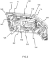
Fig.2 provides a cutaway view of a steamer head of the garment steamer shown inFig. 1 , -
Fig.3 provides a perspective interior view of the steamer head shown inFig.2 , -
Fig.4 provides a cross-sectional view of a portion of the steamer head shown inFigs. 1 to 3 , with an inset providing an enlarged view showing a first air gap between a first metal layer and a steam generator, and a second air gap between the first metal layer and a housing of the steamer head, -
Fig.5 provides a cross-sectional view of another portion of the steamer head shown inFigs. 1 to 3 , with an inset providing an enlarged view of the second air gap, -
Fig.6 provides a view of a second metal layer included in the portion shown inFig.5 fastened to part of the housing, with an inset providing an enlarged view of part of the fastening, and -
Fig.7 provides a view of the first metal layer shown inFig.4 fastened to another part of the housing. -
Fig.1 depicts agarment steamer 100 according to an example. Thegarment steamer 100 has a steamer head comprising a housing H. Thegarment steamer 100 comprises asteam generator 106 for generating steam. Thesteam generator 106 is contained within the housing H. Thesteam generator 106 is contained within. In other words, thesteam generator 106 is enclosed by the housing H. - The housing H can be regarded as being an outer housing. An external surface of the housing H is therefore contactable by a user operating the
garment care device 100. - The housing H is made of plastic material. Such a plastic housing H may assist the steamer head to be relatively lightweight, and thus enhance the manoeuvrability of the
garment steamer 100. - For example, the housing H is made of an engineering thermoplastic, such as polypropylene.
- In some embodiments, such as in the non-limiting example shown in
Fig. 1 , the housing H comprises afirst housing part 102 and asecond housing part 104. In such embodiments, thesteam generator 106 is housed between thefirst housing part 102 and thesecond housing part 104. - The
steam generator 106 can have any suitable design. In some embodiments, such as that depicted inFig.1 , thesteam generator 106 comprises atop part 108 and abottom part 110. - Referring to
Fig.2 , thetop part 108 is, for example, a cover of thesteam generator 106. - The cover defined by the
top part 108 can cover thebottom part 110 of thesteam generator 106. In such an example, a recess is defined in thebottom part 110, and asteam chamber 112 is provided by the cover closing the recess defined in thebottom part 110. - The
steam generator 106, and in particular thetop part 108 and thebottom part 110, can be made of any suitable material, such as a metal or metal alloy. Preferably, thesteam generator 106 is (at least partly) made of casted metal alloy. - For example, at least the
bottom part 110 of thesteam generator 106 is casted in a metal alloy. - More generally, the
garment steamer 100 comprises at least onemetal layer steam generator 106 and the housing H. - The at least one
metal layer steam generator 106 and spreading it over a surface area of the at least onemetal layer metal layer steam generator 106. - In other words, the at least one
metal layer steam generator 106 across the at least onemetal layer garment care device 100 reaches thermal equilibrium. - As well as the above-described heat spreading function, the at least one
metal layer - By managing heat transfer to the housing H in these ways, the at least one
metal layer garment steamer 100. - In some embodiments, the housing H, the
steam generator 106, and the at least onemetal layer - Each of the at least one
metal layer - Preferably, the at least one
metal layer - It is noted that the shape of the at least one
metal layer steam generator 106 and the housing H. - In some embodiments, such as that shown in
Figs. 1 and2 , the at least onemetal layer steam generator 106, and/or a shape which follows at least part of the profile of the housing. This may assist to enhance the compactness of thegarment steamer 100. - For example, each of the at least one
metal layer steam generator 106, and/or a curvature which follows at least part of the profile of the housing. - The at least one
metal layer first metal layer 114 extending over thetop part 108 of thesteam generator 106, and asecond metal layer 116 extending over thebottom part 110 of thesteam generator 106. In other words, thefirst metal layer 114 faces thetop part 108 of thesteam generator 106, and thesecond metal layer 116 faces thebottom part 110 of thesteam generator 106. An example of this is shown inFigs.1 and2 . - In the non-limiting example shown in
Figs. 1 and2 , thefirst metal layer 114 has a shape which follows an outer profile of thetop part 108 of thesteam generator 106. - Similarly, the
second metal layer 116 has a shape which follows an outer profile of thebottom part 110 of thesteam generator 106. - In embodiments in which the at least one
metal layer first metal layer 114 and thesecond metal layer 116, thesemetal layers - The
first metal layer 114 being separate from, in other words not connected to, thesecond metal layer 116, means that the first and second metal layers 114, 116 do not form an enclosure around thesteam generator 106. In other words, the first and second metal layers 114, 116 do not form a closed sheath or hollow shell around thesteam generator 106. Thefirst metal layer 114 being separate from thesecond metal layer 116 may assist with dissipating the heat of thesteam generator 106 within the steamer head. - Referring to
Fig.3 , an outer periphery OP1 of thefirst metal layer 114 is preferably spaced apart from an opposing outer periphery OP2 of thesecond metal layer 116 by a distance D with a value in the range [1;2] cm. - The distance D being in this [1;2] cm range can assist to balance sufficient heat dissipation via the spacing between the
first metal layer 114 and thesecond metal layer 116, with sufficient coverage of thesteam generator 106 by thefirst metal layer 114 and thesecond metal layer 116 for heat spreading and heat shielding purposes. - In some embodiments, the at least one
metal layer first metal layer 114 and thesecond metal layer 116 preferably each have a thickness being at least 0.2 mm. - Such a minimum thickness may assist the metal layer(s) 114, 116 to spread the heat generated by the
steam generator 106, whilst also ensuring that each of the at least onemetal layer - In a non-limiting example, each of the at least one
metal layer - In some embodiments, the at least one
metal layer steam generator 106 so to form afirst air gap 118 between thesteam generator 106 and the at least onemetal layer Fig.4 . - Such a
first air gap 118 between thesteam generator 106 and the at least onemetal layer - The
first air gap 118 is preferably at least 2 mm. Such a minimum spacing of 2 mm may assist to provide sufficient insulation via thefirst air gap 118 between the at least onemetal layer steam generator 106. - It is noted that the
first air gap 118 does not necessarily have a constant value all around the steam generator. - In embodiments in which the at least one
metal layer first metal layer 114 and thesecond metal layer 116, thefirst air gap 118 can be present between thetop part 108 of thesteam generator 106 and thefirst metal layer 114, and/or between thebottom part 110 of thesteam generator 106 and thesecond metal layer 116. - In the non-limiting example shown in the Figures, the
first air gap 118 is present between thetop part 108 of thesteam generator 106 and thefirst metal layer 114, and between thebottom part 110 of thesteam generator 106 and thesecond metal layer 116. - Referring to
Figs.4 and 5 , the at least onemetal layer second air gap 120 between the at least onemetal layer - Such a
second air gap 120 between the at least onemetal layer - The
second air gap 120 is preferably at least 0.5 mm. Such a minimum spacing of 0.5 mm may assist to provide sufficient insulation via the second air gap between the at least onemetal layer - It is noted that the
second air gap 120 does not necessarily have a constant value all around the steam generator. - In embodiments in which the at least one
metal layer first metal layer 114 and thesecond metal layer 116, thesecond air gap 120 can be present between the housing H and thefirst metal layer 114, and/or between the housing H and thesecond metal layer 116. - In the non-limiting example shown in
Figs.4 and 5 , thesecond air gap 120 is present between thefirst housing part 102 and thefirst metal layer 114, and between thesecond housing part 104 and thesecond metal layer 116. - In embodiments in which both the
first air gap 118 and thesecond air gap 120 are provided, thefirst air gap 118 is preferably wider than thesecond air gap 120. This may assist to manage heat transfer from thesteam generator 106 to the housing H such as to minimise hot spots on the housing H. - In some embodiments, the at least one
metal layer reflective surface reflective surface steam generator 106. Indeed, a smooth shiny surface is a good reflector of light and radiant heat. Polishing is a mean to achieve the shiny/glossy surface.Figs.6 and 7 show the location (but do not illustrate the reflectivity) of the polishedreflective surface - Such a
reflective surface steam generator 106, so away from the housing H. - In embodiments in which the at least one
metal layer first metal layer 114 and thesecond metal layer 116, thefirst metal layer 114 can include a firstreflective surface 122 facing thesteam generator 106, and/or thesecond metal layer 116 can include a secondreflective surface 124 facing thesteam generator 106. - In the non-limiting example shown in the Figures, the steam generator-facing surface of the
second metal layer 116 comprises a recessed portion RP which is recessed relative to neighbouring regions of the surface. Such a recessed portion RP may be provided to, for instance, accommodate a fuse and/orthermostat 125, for controlling thesteam generator 106. - In this particular example, the above-described polished
reflective surface 124 is also present in the recessed portion RP. - In some embodiments, such as the non-limiting example shown in the Figures, the at least one
metal layer - Such discrete fastening points 126A, 126B, 126C, 128A, 128B may assist to minimise direct heat transfer from the at least one
metal layer - Any suitable fastening/locking principle can be used to fasten the at least one
metal layer - In the non-limiting example shown in the Figures, the fastening of the
second metal layer 116 to thesecond housing part 104 is achieved via interlock catches 126A, 126B, such as interlock plastic catches 126A, 126B, and ascrew fastener 130, as best shown inFigs.1 ,5 and6 . - In embodiments in which the at least one
metal layer metal layer - This is because the relatively rigid metal layer(s) 114, 116 in combination with the rigid locking principle provided by the interlock catch(es) 126A, 126B can reduce the risk of detachment or shape change of the metal layer(s) 114, 116 during prolonged usage.
- For example, the
second metal layer 116 is fastened to thesecond housing part 104 via interlock catches 126A, 126B and is made of aluminium having a thickness of at least 0.2 mm. - In the non-limiting example shown in the Figures, the fastening of the
first metal layer 114 to thefirst housing part 102 is achieved viascrew fasteners Figs.1 and4 . For example, thefirst metal layer 114 fastened to thefirst housing part 102 via thescrew fasteners - However, the above-described one or more interlock plastic catches can be alternatively or additionally used to fasten the first metal layer to the first housing part (not shown).
- More generally, the at least one
metal layer steam generator 106. Hence heat may not be directly transferred from thesteam generator 106 to the metal layer(s) 114, 116 by conduction. This, in turn, can enable various fastening/locking principles, such as the above-described interlock catch(es) 126A, 126B, to be used for fastening the at least onemetal layer - It is noted that the interlock catch(es) 126A, 126B can, for instance, be provided at the base of one or more of the
posts 134A-134B-134C-134D-134E-134F-134G-134H-134I included in thefirst housing part 102 and thesecond housing part 104 in which threaded holes are provided for fastening thehousing parts - Referring again to
Fig.4 , a lockingsurface 136 can be defined as the area over which therespective metal layer fastening point - The locking
surface 136 is preferably minimised in order to minimise direct heat conduction from themetal layer surface 136 is restricted to at most 80 mm2. This upper limit may, for example, correspond to a circular locking surface whose diameter is about 10 mm. - In general, it is preferred to have a gap between the metal layer(s) and the housing, except at the mounting points and/or some discrete point for better support of the metal layer(s). Total contact area between the metal layer and the housing should not be more than 25% of the surface area of metal layer facing the housing.
- More generally, the
garment steamer 100 is preferably ahandheld garment steamer 100. - Referring again to
Figs. 1 and2 , thesteam generator 106, awater tank 138 for storing water for supplying to thesteam generator 106, and atreatment plate 140 in which at least onesteam outlet 142 is provided for releasing the steam can be integrated into a single portable hand unit when thegarment steamer 100 is such ahandheld garment steamer 100. - In the non-limiting example shown in figures, the steam generator comprises a heating element 150 for heating the steam generator to temperature above 100 degree Celsius for generating steam with water supplied by the water tank, and the heating element is being controlled by suitable control means, for example a thermostat.
- The at least one
metal layer garment steamer 100 is ahandheld garment steamer 100 because the at least onemetal layer - In some embodiments, such as the non-limiting example shown in the Figures, the steamer head comprises a mounting
member 143 arranged to secure thetreatment plate 140 to the housing H. - The
garment steamer 100 preferably comprises ahandle 144 for holding thegarment steamer 100, with the steamer head being arranged at an end of thehandle 144. - In some embodiments, such as that shown in
Fig.1 , thehandle 144 includes the water tank, 138. - Following filling of the
water tank 138, thegarment steamer 100 can be used to steam garments once, for instance, thegarment steamer 100 is connected to a mains supply of electricity via apower cord 146. In the non-limiting example shown inFig.1 , thepower cord 146 connects to thehandle 144 via apower cord grommet 148. - The above embodiments as described are only illustrative, and not intended to limit the technique approaches of the present invention. Although the present invention is described in detail referring to the preferable embodiments, those skilled in the art will understand that the technique approaches of the present invention can be modified or equally displaced without departing from the protective scope of the claims of the present invention. In particular, although the invention has been described based on a garment steamer, it can be applied to any household device, for example handheld household device, having a steam generator. In the claims, the word "comprising" does not exclude other elements or steps, and the indefinite article "a" or "an" does not exclude a plurality. Any reference signs in the claims should not be construed as limiting the scope.
Claims (15)
- A garment steamer (100) comprising:- a steamer head comprising a housing (H) made of plastic material,- a steam generator (106) for generating steam, the steam generator being contained within the housing, and- at least one metal layer (114, 116) being arranged between the steam generator and the housing.
- The garment steamer (100) according to claim 1, wherein the at least one metal layer (114, 116) is spaced from the steam generator so as to form a first air gap (118) between the steam generator (106) and the at least one metal layer.
- The garment steamer (100) according to claim 2, wherein said first air gap (118) is at least 2 mm.
- The garment steamer (100) according to any of claims 1 to 3, wherein the at least one metal layer (114, 116) is spaced from the housing (H) to form a second air gap (120) between the at least one metal layer and the housing.
- The garment steamer (100) according to claim 4 as according to claim 2 or 3, wherein said first air gap (118) is wider than said second air gap (120).
- The garment steamer (100) according to claim 4 or claim 5, wherein said second air gap (120) is at least 0.5 mm.
- The garment steamer (100) according to any one of the preceding claims, wherein the at least one metal layer (114, 116) comprises a first metal layer (114) extending over a top part (108) of the steam generator (106), and a second metal layer (116) extending over a bottom part (110) of the steam generator.
- The garment steamer (100) according to claim 7, wherein the first metal layer (114) and the second metal layer (116) each have a thickness being at least 0.2 mm.
- The garment steamer (100) according to claim 7 or 8, wherein the first metal layer (114) is separate from the second metal layer (116).
- The garment steamer (100) according to any one of claims 7 to 9, wherein an outer periphery (OP1) of the first metal layer (114) is spaced apart from an opposing outer periphery (OP2) of the second metal layer by a distance (D) with a value in the range [1;2] cm.
- The garment steamer (100) according to any one of the preceding claims, wherein the at least one metal layer (114, 116) is made of aluminium.
- The garment steamer (100) according to any one of the preceding claims, wherein the at least one metal layer (114, 116) comprises a polished reflective surface (122, 124), said polished reflective surface facing the steam generator (106).
- The garment steamer (100) according to any one of the preceding claims, wherein the at least one metal layer (114, 116) is fastened to the housing (H) at discrete fastening points (126A, 126B, 126C, 128A, 128B).
- The garment steamer (100) according to any one of the preceding claims, wherein the steam generator (106) is made of casted metal alloy.
- The garment steamer (100) according to any one of the preceding claims, wherein the garment steamer is a handheld garment steamer.
Priority Applications (7)
| Application Number | Priority Date | Filing Date | Title |
|---|---|---|---|
| EP21212471.3A EP4190966A1 (en) | 2021-12-06 | 2021-12-06 | Garment steamer with heat protection |
| PCT/EP2022/082859 WO2023104508A1 (en) | 2021-12-06 | 2022-11-22 | Garment steamer with heat protection |
| PL22803343.7T PL4444948T3 (en) | 2021-12-06 | 2022-11-22 | Garment steamer with heat protection |
| KR1020247022240A KR20240121268A (en) | 2021-12-06 | 2022-11-22 | Garment steamer with heat protection function |
| EP22803343.7A EP4444948B1 (en) | 2021-12-06 | 2022-11-22 | Garment steamer with heat protection |
| CN202223248727.0U CN219621464U (en) | 2021-12-06 | 2022-12-05 | Steam ironing machine |
| CN202211578882.0A CN116219720A (en) | 2021-12-06 | 2022-12-05 | Steam ironing machine with heat protection |
Applications Claiming Priority (1)
| Application Number | Priority Date | Filing Date | Title |
|---|---|---|---|
| EP21212471.3A EP4190966A1 (en) | 2021-12-06 | 2021-12-06 | Garment steamer with heat protection |
Publications (1)
| Publication Number | Publication Date |
|---|---|
| EP4190966A1 true EP4190966A1 (en) | 2023-06-07 |
Family
ID=78821804
Family Applications (2)
| Application Number | Title | Priority Date | Filing Date |
|---|---|---|---|
| EP21212471.3A Withdrawn EP4190966A1 (en) | 2021-12-06 | 2021-12-06 | Garment steamer with heat protection |
| EP22803343.7A Active EP4444948B1 (en) | 2021-12-06 | 2022-11-22 | Garment steamer with heat protection |
Family Applications After (1)
| Application Number | Title | Priority Date | Filing Date |
|---|---|---|---|
| EP22803343.7A Active EP4444948B1 (en) | 2021-12-06 | 2022-11-22 | Garment steamer with heat protection |
Country Status (5)
| Country | Link |
|---|---|
| EP (2) | EP4190966A1 (en) |
| KR (1) | KR20240121268A (en) |
| CN (2) | CN219621464U (en) |
| PL (1) | PL4444948T3 (en) |
| WO (1) | WO2023104508A1 (en) |
Citations (4)
| Publication number | Priority date | Publication date | Assignee | Title |
|---|---|---|---|---|
| WO2013133573A2 (en) * | 2012-03-05 | 2013-09-12 | Kim Hwa Sik | Standing steam iron |
| CN105463815A (en) * | 2016-02-03 | 2016-04-06 | 莱克电气绿能科技(苏州)有限公司 | Ironing head with secondary heating pot |
| CN206646306U (en) * | 2017-03-02 | 2017-11-17 | 浙江华光电器集团有限公司 | A kind of Steam iron and brush and garment steamer with backwater structure |
| CN209443263U (en) * | 2019-01-24 | 2019-09-27 | 宁波市聚梦智能科技有限公司 | Vapour iron |
-
2021
- 2021-12-06 EP EP21212471.3A patent/EP4190966A1/en not_active Withdrawn
-
2022
- 2022-11-22 KR KR1020247022240A patent/KR20240121268A/en active Pending
- 2022-11-22 WO PCT/EP2022/082859 patent/WO2023104508A1/en not_active Ceased
- 2022-11-22 PL PL22803343.7T patent/PL4444948T3/en unknown
- 2022-11-22 EP EP22803343.7A patent/EP4444948B1/en active Active
- 2022-12-05 CN CN202223248727.0U patent/CN219621464U/en active Active
- 2022-12-05 CN CN202211578882.0A patent/CN116219720A/en active Pending
Patent Citations (4)
| Publication number | Priority date | Publication date | Assignee | Title |
|---|---|---|---|---|
| WO2013133573A2 (en) * | 2012-03-05 | 2013-09-12 | Kim Hwa Sik | Standing steam iron |
| CN105463815A (en) * | 2016-02-03 | 2016-04-06 | 莱克电气绿能科技(苏州)有限公司 | Ironing head with secondary heating pot |
| CN206646306U (en) * | 2017-03-02 | 2017-11-17 | 浙江华光电器集团有限公司 | A kind of Steam iron and brush and garment steamer with backwater structure |
| CN209443263U (en) * | 2019-01-24 | 2019-09-27 | 宁波市聚梦智能科技有限公司 | Vapour iron |
Also Published As
| Publication number | Publication date |
|---|---|
| CN116219720A (en) | 2023-06-06 |
| WO2023104508A1 (en) | 2023-06-15 |
| EP4444948B1 (en) | 2025-01-15 |
| KR20240121268A (en) | 2024-08-08 |
| EP4444948A1 (en) | 2024-10-16 |
| PL4444948T3 (en) | 2025-03-10 |
| CN219621464U (en) | 2023-09-01 |
Similar Documents
| Publication | Publication Date | Title |
|---|---|---|
| US6509550B1 (en) | Roasting oven with dual heating elements | |
| US7012221B2 (en) | Roasting oven with dual heating elements | |
| EP4444948B1 (en) | Garment steamer with heat protection | |
| KR101083388B1 (en) | Apparatus for condensing and suppling of steam in electric cooker | |
| KR101378499B1 (en) | Heating apparatus applied to desk | |
| KR20090000554U (en) | Portable Regenerative Poultry Equipment | |
| KR101094243B1 (en) | Steam Condenser of Rice Cooker | |
| CN215336614U (en) | Foot warmer | |
| KR200419836Y1 (en) | Foot sleeping bag using cotton heating element | |
| KR102226319B1 (en) | Heating apparatus | |
| KR200489505Y1 (en) | Foot bathing apparatus of dry type with wet type | |
| KR200441979Y1 (en) | Portable Regenerative Poultry Equipment | |
| KR20200074480A (en) | Personalized Thermal Skin Massage Device | |
| JPH119443A (en) | Electromagnetic induction heating type rice cooker | |
| KR200215974Y1 (en) | Refrigerator of cosmetic | |
| KR20090005341U (en) | Poultice belt | |
| JPH1199070A (en) | Cookware | |
| KR200428270Y1 (en) | Hot water circulation mat | |
| KR920002782Y1 (en) | Baby Bathtub Device | |
| KR200277590Y1 (en) | Medical bed mat | |
| KR200406883Y1 (en) | Thermal Therapy | |
| KR200413334Y1 (en) | Dry and wet tofu sauna device | |
| SU942754A1 (en) | Portable dry air bath | |
| KR20220107522A (en) | Portable Device for Hot-heat Fomentation and Heating Method thereof | |
| JP3976028B2 (en) | Electric rice cooker |
Legal Events
| Date | Code | Title | Description |
|---|---|---|---|
| PUAI | Public reference made under article 153(3) epc to a published international application that has entered the european phase |
Free format text: ORIGINAL CODE: 0009012 |
|
| STAA | Information on the status of an ep patent application or granted ep patent |
Free format text: STATUS: THE APPLICATION HAS BEEN PUBLISHED |
|
| AK | Designated contracting states |
Kind code of ref document: A1 Designated state(s): AL AT BE BG CH CY CZ DE DK EE ES FI FR GB GR HR HU IE IS IT LI LT LU LV MC MK MT NL NO PL PT RO RS SE SI SK SM TR |
|
| STAA | Information on the status of an ep patent application or granted ep patent |
Free format text: STATUS: THE APPLICATION IS DEEMED TO BE WITHDRAWN |
|
| 18D | Application deemed to be withdrawn |
Effective date: 20231208 |