EP4190727A1 - Device for moving containers - Google Patents
Device for moving containers Download PDFInfo
- Publication number
- EP4190727A1 EP4190727A1 EP22211070.2A EP22211070A EP4190727A1 EP 4190727 A1 EP4190727 A1 EP 4190727A1 EP 22211070 A EP22211070 A EP 22211070A EP 4190727 A1 EP4190727 A1 EP 4190727A1
- Authority
- EP
- European Patent Office
- Prior art keywords
- containers
- drum
- along
- distributing drum
- forward direction
- Prior art date
- Legal status (The legal status is an assumption and is not a legal conclusion. Google has not performed a legal analysis and makes no representation as to the accuracy of the status listed.)
- Withdrawn
Links
Images



Classifications
-
- B—PERFORMING OPERATIONS; TRANSPORTING
- B65—CONVEYING; PACKING; STORING; HANDLING THIN OR FILAMENTARY MATERIAL
- B65G—TRANSPORT OR STORAGE DEVICES, e.g. CONVEYORS FOR LOADING OR TIPPING, SHOP CONVEYOR SYSTEMS OR PNEUMATIC TUBE CONVEYORS
- B65G47/00—Article or material-handling devices associated with conveyors; Methods employing such devices
- B65G47/52—Devices for transferring articles or materials between conveyors i.e. discharging or feeding devices
- B65G47/68—Devices for transferring articles or materials between conveyors i.e. discharging or feeding devices adapted to receive articles arriving in one layer from one conveyor lane and to transfer them in individual layers to more than one conveyor lane or to one broader conveyor lane, or vice versa, e.g. combining the flows of articles conveyed by more than one conveyor
- B65G47/71—Devices for transferring articles or materials between conveyors i.e. discharging or feeding devices adapted to receive articles arriving in one layer from one conveyor lane and to transfer them in individual layers to more than one conveyor lane or to one broader conveyor lane, or vice versa, e.g. combining the flows of articles conveyed by more than one conveyor the articles being discharged or distributed to several distinct separate conveyors or to a broader conveyor lane
-
- B—PERFORMING OPERATIONS; TRANSPORTING
- B65—CONVEYING; PACKING; STORING; HANDLING THIN OR FILAMENTARY MATERIAL
- B65B—MACHINES, APPARATUS OR DEVICES FOR, OR METHODS OF, PACKAGING ARTICLES OR MATERIALS; UNPACKING
- B65B43/00—Forming, feeding, opening or setting-up containers or receptacles in association with packaging
- B65B43/42—Feeding or positioning bags, boxes, or cartons in the distended, opened, or set-up state; Feeding preformed rigid containers, e.g. tins, capsules, glass tubes, glasses, to the packaging position; Locating containers or receptacles at the filling position; Supporting containers or receptacles during the filling operation
- B65B43/50—Feeding or positioning bags, boxes, or cartons in the distended, opened, or set-up state; Feeding preformed rigid containers, e.g. tins, capsules, glass tubes, glasses, to the packaging position; Locating containers or receptacles at the filling position; Supporting containers or receptacles during the filling operation using rotary tables or turrets
-
- B—PERFORMING OPERATIONS; TRANSPORTING
- B65—CONVEYING; PACKING; STORING; HANDLING THIN OR FILAMENTARY MATERIAL
- B65B—MACHINES, APPARATUS OR DEVICES FOR, OR METHODS OF, PACKAGING ARTICLES OR MATERIALS; UNPACKING
- B65B43/00—Forming, feeding, opening or setting-up containers or receptacles in association with packaging
- B65B43/42—Feeding or positioning bags, boxes, or cartons in the distended, opened, or set-up state; Feeding preformed rigid containers, e.g. tins, capsules, glass tubes, glasses, to the packaging position; Locating containers or receptacles at the filling position; Supporting containers or receptacles during the filling operation
- B65B43/52—Feeding or positioning bags, boxes, or cartons in the distended, opened, or set-up state; Feeding preformed rigid containers, e.g. tins, capsules, glass tubes, glasses, to the packaging position; Locating containers or receptacles at the filling position; Supporting containers or receptacles during the filling operation using roller-ways or endless conveyors
-
- B—PERFORMING OPERATIONS; TRANSPORTING
- B65—CONVEYING; PACKING; STORING; HANDLING THIN OR FILAMENTARY MATERIAL
- B65B—MACHINES, APPARATUS OR DEVICES FOR, OR METHODS OF, PACKAGING ARTICLES OR MATERIALS; UNPACKING
- B65B57/00—Automatic control, checking, warning, or safety devices
- B65B57/02—Automatic control, checking, warning, or safety devices responsive to absence, presence, abnormal feed, or misplacement of binding or wrapping material, containers, or packages
- B65B57/06—Automatic control, checking, warning, or safety devices responsive to absence, presence, abnormal feed, or misplacement of binding or wrapping material, containers, or packages and operating to control, or to stop, the feed of articles or material to be packaged
-
- B—PERFORMING OPERATIONS; TRANSPORTING
- B65—CONVEYING; PACKING; STORING; HANDLING THIN OR FILAMENTARY MATERIAL
- B65B—MACHINES, APPARATUS OR DEVICES FOR, OR METHODS OF, PACKAGING ARTICLES OR MATERIALS; UNPACKING
- B65B57/00—Automatic control, checking, warning, or safety devices
- B65B57/20—Applications of counting devices for controlling the feed of articles
-
- B—PERFORMING OPERATIONS; TRANSPORTING
- B65—CONVEYING; PACKING; STORING; HANDLING THIN OR FILAMENTARY MATERIAL
- B65B—MACHINES, APPARATUS OR DEVICES FOR, OR METHODS OF, PACKAGING ARTICLES OR MATERIALS; UNPACKING
- B65B65/00—Details peculiar to packaging machines and not otherwise provided for; Arrangements of such details
- B65B65/003—Packaging lines, e.g. general layout
- B65B65/006—Multiple parallel packaging lines
-
- B—PERFORMING OPERATIONS; TRANSPORTING
- B65—CONVEYING; PACKING; STORING; HANDLING THIN OR FILAMENTARY MATERIAL
- B65G—TRANSPORT OR STORAGE DEVICES, e.g. CONVEYORS FOR LOADING OR TIPPING, SHOP CONVEYOR SYSTEMS OR PNEUMATIC TUBE CONVEYORS
- B65G47/00—Article or material-handling devices associated with conveyors; Methods employing such devices
- B65G47/74—Feeding, transfer, or discharging devices of particular kinds or types
- B65G47/84—Star-shaped wheels or devices having endless travelling belts or chains, the wheels or devices being equipped with article-engaging elements
- B65G47/846—Star-shaped wheels or wheels equipped with article-engaging elements
-
- B—PERFORMING OPERATIONS; TRANSPORTING
- B65—CONVEYING; PACKING; STORING; HANDLING THIN OR FILAMENTARY MATERIAL
- B65B—MACHINES, APPARATUS OR DEVICES FOR, OR METHODS OF, PACKAGING ARTICLES OR MATERIALS; UNPACKING
- B65B2210/00—Specific aspects of the packaging machine
- B65B2210/02—Plurality of alternative input or output lines or plurality of alternative packaging units on the same packaging line for improving machine flexibility
-
- B—PERFORMING OPERATIONS; TRANSPORTING
- B65—CONVEYING; PACKING; STORING; HANDLING THIN OR FILAMENTARY MATERIAL
- B65B—MACHINES, APPARATUS OR DEVICES FOR, OR METHODS OF, PACKAGING ARTICLES OR MATERIALS; UNPACKING
- B65B29/00—Packaging of materials presenting special problems
- B65B29/02—Packaging of substances, e.g. tea, which are intended to be infused in the package
- B65B29/022—Packaging of substances, e.g. tea, which are intended to be infused in the package packaging infusion material into capsules
Definitions
- the present invention concerns the field of transportation, typically for the respective filling of containers, in particular for containers such as coffee capsules and similar elements.
- Systems for moving containers and which typically comprise an orientator adapted to randomly receive objects and to orient them in a predefined way, such as to move them towards a successive station, for example by means of air channels or moving carpets or belts, are known.
- the orientator is typically configured such as to deliver a single row of objects.
- the successive station for example a station for filling coffee capsules, is configured such as to receive a plurality of rows of containers.
- Object of the present invention is thus to solve the problems discussed above. Further object of the present invention is that of providing a system for transporting containers which allows to simply and effectively distribute the same row of objects along several parallel rows.
- Further object of the present invention is to make such transport system in a compact way.
- Further object of the present invention is to make a device which can selectively distribute the objects towards the desired rows.
- an aspect of the present invention concerns a device for moving containers comprising: a first movement element configured such as to move the containers; a distributing drum adapted to receive at least one row of objects and to deliver the objects of the same row in separate rows.
- the distributing drum is rotatable around a rotation axis and is configured such as the entry of the containers into the distributing drum along a row occurs along a first forward direction being substantially axial to the distributing drum with respect to the respective rotation axis, and the coming out of the containers, along several rows separated by the distributing drum, occurs in a substantially perpendicular direction with respect to the first forward direction.
- the distributing drum is a compact element which allows to effectively transform the same row of containers into a plurality of different rows of containers.
- the drum can typically accommodate a predetermined number of containers. Following its rotation, they are delivered to the successive element along several parallel rows.
- the drum can successively receive further containers which will in turn be delivered along several separate rows as the drum rotates.
- the device comprises a separating element arranged downstream of the drum and adapted to modify the distance between the containers coming out of the drum.
- the separating element is adapted to modify the transversal distance between the containers, i.e. the distance measured in axial direction with respect to the rotation axis of the drum (and thus perpendicular to the second forward direction of the containers exiting the drum itself).
- the separating element comprises a plurality of channels and at least part of the channels are not parallel to one another. This way, the transversal distance between the containers is modified when the containers move forward along such channels.
- the drum comprises a plurality of sectors arranged in series along the rotation axis and each sector is able to accommodate one or more containers, preferably a single container.
- each sector has a seat for one or more containers, preferably a seat for a single container.
- the sectors are integral to one another when rotating. In other words, when the drum rotates, all the respective sectors rotate synchronously with each another.
- the drum is rotated by a shaft and at least part of the sectors are selectively constrainable to, and releasable from, such rotation shaft, such as to be able to select which sectors to rotate.
- the device comprises at least one sensor arranged at the drum and adapted to detect the presence of the containers at the drum.
- the device comprises a second movement element arranged downstream of the drum and adapted to receive a plurality of rows of containers from the drum.
- An aspect of the present invention further concerns a process for moving containers by means of a device according to one or more of the preceding claims, comprising the steps of: moving the containers along the first movement element; delivering at least one row of containers to the distributing drum along a first forward direction axial with respect to the distributing drum; rotating the distributing drum; delivering from the drum, in a plurality of rows, the containers initially arranged along the same row, along a second forward direction substantially perpendicular to the first forward direction.
- the method further comprises the step of separating the containers from one another, i.e. of increasing the transversal distance between them by means of a separating element.
- a device 1 for moving containers 100 comprises a first movement element 2 adapted to move containers along at least one row towards a distributing drum 3.
- the first movement element precisely comprises one row of containers 100.
- the possibility to have a greater number of rows is not however excluded, typically if the drum 3 has large dimensions, such as to be able to receive more rows parallel to one another.
- feeding several rows would be advantageous if the radius of the drum section would be particularly large and thus the curvature of the drum section small, such as to be able to have several rows of seats, substantially at the same height, in the drum.
- the effect of the drum would anyhow stay unvaried, i.e. that of distributing the containers that were initially arranged in the same row along several rows.
- the containers 100 can have different shapes. Preferably, they have a closed body on the bottom and typically have on opening on top. Typically, the opening has a flange, although embodiments adapted to cooperate with containers 100 not provided with flanges are possible.
- a preferred container 100 used with the present device 1 is a coffee capsule or a container having similar shape.
- the first movement element 2 shown only schematically in figures 5A - 5D , is known in the art and not discussed in detail herein. Typically, it is shaped like a conveyor belt, or an air channel, or a belt, etc.
- the first movement element 2 typically receives the containers 100 from a source.
- the device 1 can comprise an orientator element known in the art and not shown in detail in the figures and configured to arrange the containers 100 according to a predefined orientation inside the first movement element 2, typically with the cavity facing upward.
- drum 3 a distributing drum 3, henceforth also “drum 3,” is present downstream of the first movement element 2.
- the drum 3 is rotatable around a rotation axis A.
- Such rotation can occur by means of different methods known to the technician of the field.
- the device has an electric motor M adapted to control a rotating shaft 4 on which the drum 3 is mounted.
- the rotating shaft 4 can be controlled directly by the motor M or gears can act as reducers and are interposed between the shaft 4 and the motor M.
- the device 1 is configured such as the first movement element 2 feeds the containers 100 arranged along at least one row, along a first forward direction D1 axial with respect to the rotation axis A, i.e. parallel thereto and arranged at a distance from the rotation axis A.
- axial does not mean that it coincides with the rotation axis A but that it is substantially parallel thereto, such as, when considering a plane orthogonal to the rotation axis A, such plane is substantially orthogonal also to the first forward direction D 1.
- the drum 3 is provided with a plurality of radial teeth 3a.
- the space between successive teeth 3a i.e. radially arranged in succession on the drum 3) forms seats 3b into which the containers 100 can be at least partially inserted.
- the containers 100 are preferably provided with a flange 103 arranged at the upper portion thereof.
- the teeth 3a are typically arranged such as to be able to support the flange of the containers 100.
- the distance between two teeth 3a arranged successively in radial direction on the drum 3 is preferably less than the diameter (or the greatest dimension) of the flange of the container 100, such as, as discussed, the containers 100 can be supported by the respective flange within the seat 3b.
- the device is typically shaped such as to support the containers 100 on the bottom and such as to cooperate with a different portion of the container 100, typically with its body, such as to allow it to be pull out of the seat 3b.
- the drum has a plurality of sectors 31 - 36 arranged in succession along the rotation axis A of the drum 3. Each sector is provided with a seat 3b adapted to accommodate one or more containers, each seat 3b is preferably configured to accommodate a single container 100.
- the number of sectors 31 - 36 can obviously vary in different embodiments and typically corresponds to the maximum number of rows along which the containers 100 coming out of the drum 3 can be organized.
- the seats 3b are typically arranged so that a container 100, when moving forward along the first forward direction D1, can cross the various seats 3b of the drum 3 arranged in axial succession (with respect to the rotation axis A), until reaching the furthest seat along the forward direction D1 and which seat is still not stably occupied by a container 100.
- the device 1 is thus preferably configured so that the containers 100 can move forward along the seats 3b of the drum until all seats 3b are stably occupied by a container 100.
- a container 100 stably occupies a seat 3b when it cannot move forward along the forward direction D1, since a blocking element (for example a wall of the device) is immediately present downstream of the seat 3b or a further seat 3b is present and in which a different container 100, which cannot in turn move forward along the forward direction D1, since it is in turn blocked in its travel by a blocking element or by a further container 100 in the successive seat 3b, is present.
- a blocking element for example a wall of the device
- the device 1 preferably comprises a sensor 5 known in the art and adapted to detect the filling of all seats 3b by means of the containers. It is possible to provide a plurality of sensors 5 (for example one for each seat), or a single sensor 5 adapted, for example, to detect the presence of a container 100 in the last seat 3b, i.e. the last seat 3b the containers 100 encounter during their travel along the first forward direction D1. Additionally or alternatively, it is possible to provide the device 1 with a sensor, for example a photocell, adapted to allow to count the containers 100 entering the drum 3.
- a sensor for example a photocell
- the containers 100 are fed into the drum 3 continuously, thus, if a container reaches the last seat 3b, the preceding seats are also occupied by containers.
- the sectors 31 - 36 of the drum 3 can be integral to one another when rotating, or at least part of the sectors 31 - 36 can rotate independently of the other sectors of the drum 3.
- the sectors 31 - 36 can be rotated around the rotation axis A independently of one another.
- the rotation of the drum 3 allows to move the containers 100 and, in particular, to deliver such containers 100 along a second forward direction D2 substantially orthogonal to the rotation axis A, and thus to the first forward direction D1.
- the drum 3 is typically provided with an ejecting element 6 for ejecting the containers 100 from the drum 3 and in particular from the respective seats 3b.
- the interaction between such ejecting element 6 and the containers 100 helps determine the second forward direction D2.
- the second forward direction D2 is substantially orthogonal to the first forward direction D1, at least until the ejecting element 6 cooperates with the containers 100.
- a preferred method of determining the relationship between the first forward direction D1 and the second forward direction D2 is that of considering a plan view of the device 1 in use, i.e. a substantially horizontal plane arranged above the device 1 during use.
- a plan view of the device 1 in use i.e. a substantially horizontal plane arranged above the device 1 during use.
- the containers 100 present in the drum 3 are moved at a rotation thereof along a circular path having the rotation axis A as the center, since they rotate integrally with a portion of the drum r placed at a distance from the rotation axis A itself. Successively, they are delivered from the drum 3 along the second forward direction D2.
- the delivery of the containers starts with the interaction between the containers 100 and the ejecting element 6.
- the movement of the containers 100 on the drum 3 is thus typically tangential to the rotation axis A until the intervention of the ejecting element 6, thanks to which ejecting element the containers are moved along the second forward direction D2, as discussed above.
- the ejecting element comprises a plurality of guides 6a adapted to come into contact with a portion of the containers 100, typically with the flange of the containers 100 when they are moved by the drum 3. During the delivery of the containers 100 from the drum 3, the containers can thus move forward along the guides pushed by the drum 3, preferably by the teeth 3a of the drum 3.
- the device 1 comprises a separating element 7 adapted to modify and, in particular, increase the distance between the containers 100 measured in a direction axial to the rotation axis A, i.e. a direction parallel to such axis A.
- the containers 100 preferably move forward along third forward directions D3. At least part of such directions are divergent from one another, preferably considering the orthogonal projection of such third forward directions on the previously described horizontal plane.
- such separating element 7 comprises a plurality of channels 7a. At least part of the channels 7a are arranged branching off from one another, such as to increase the transversal distance between the containers 100, i.e. the distance measured parallel to the rotation axis A of the drum 3.
- the device 1 has a second movement element 8 adapted to move/transport the containers 100 downstream of the drum 3, typically downstream of the separating element 7.
- Such second movement element 8 typically comprises a plurality of channels along which the containers can slide.
- Different movement elements such as belt, air conveyed, etc., known in the art can be used as a second movement element.
- Such second movement element 8 shown only schematically in figures 5A - 5D , is configured such as to allow the forward movement of a plurality of containers along several rows, typically parallel to one another.
- the device 1 feeds, by means of the first movement element 2, a plurality of containers 100 arranged along at least one row, to the drum 3, typically precisely along a single row, by moving them along the first forward direction D1.
- a number N of containers 100 thus fills the drum 3.
- the drum 3 When the drum 3 has reached the desired capacity of containers 100, thus when the drum 3 accommodates N containers arranged along a row, the drum 3 is rotated. When the drum 3 moves, the containers 100 are moved and delivered from the drum along the second forward direction D2, substantially orthogonally to the first forward direction D1.
- all the sectors 31 - 36 of the drum 3 move forward synchronously, such as to deliver all N containers along N rows.
- the drum 3 thus receives N containers 100 along a row and the movement of the drum itself creates N rows of containers, each initially containing a single container 100. Repeating the operations of the drum 100 leads to filling the N rows of containers downstream of the drum 3 with a plurality of containers for each row.
- the device forms N rows of containers 100 each provided with M containers 100, as schematized for example in figures 5A - 5C .
- N 6
- M 4
- the device 1 is able to form 6 rows, each comprising 4 containers, starting from a condition in which the 24 containers were instead initially aligned along a single row.
- FIG 5C the containers delivered in the preceding cycles are shown dotted.
- N containers 100 it is possible to fill the drum with N containers 100. During the movement of the drum only part of the sectors is moved, thus X sectors are not rotated and do not thus deliver the respective containers. In such case, N - X rows of containers are formed. After M filling and delivery cycles, N - X rows of containers are formed, each containing M containers.
- each sector is always operated such as to deliver the respective container or is always operated such as to not deliver the respective container, are described.
- the device 1 forms 6 rows of containers exiting the drum 3, 4 of which have 5 containers, while the remaining 2 contain 3 containers.
- each row delivers N containers to the drum 3.
- N rows of containers are formed, each of the N rows exiting the drum containing a number of containers equal to the number of rows entering in the drum.
- the device could be configured to feed two rows of containers to the drum 3 and, in particular, six containers from each of the two rows. Following the rotation of the drum 3, six rows of containers are formed at the exit, each row containing two containers. By repeating the operations of the drum, it is possible to fill the rows coming out of the drum 3 over time.
Landscapes
- Engineering & Computer Science (AREA)
- Mechanical Engineering (AREA)
- Microelectronics & Electronic Packaging (AREA)
- Specific Conveyance Elements (AREA)
Abstract
Device (1) for moving containers (100), comprising: a first movement element (2) configured such as to move the containers (100); a distributing drum (3) adapted to receive at least one row of objects (100) and to deliver the objects (100) of the same row in separate rows; wherein said distributing drum (3) is rotatable around a rotation axis (A) and is configured such as the entry of said containers (100) into said distributing drum (3) along a row is carried out along a first forward direction (D1) substantially axial to the distributing drum (3) with respect to said rotation axis (A), and the delivery of the containers (100) initially arranged along the same row is carried out along several rows separated from one another, along a second forward direction (D2) arranged substantially orthogonal to said first forward direction (D1).
Description
- The present invention concerns the field of transportation, typically for the respective filling of containers, in particular for containers such as coffee capsules and similar elements.
- Systems for moving containers and which typically comprise an orientator adapted to randomly receive objects and to orient them in a predefined way, such as to move them towards a successive station, for example by means of air channels or moving carpets or belts, are known.
- The orientator is typically configured such as to deliver a single row of objects. The successive station, for example a station for filling coffee capsules, is configured such as to receive a plurality of rows of containers.
- Solutions which provide for the passage from one to more rows, for examples by means of movable arms or distribution pushers, are known.
- Such solutions are complex, costly and not always effective, or at least not always flexible in quickly and rapidly directing objects towards the desired rows.
- Object of the present invention is thus to solve the problems discussed above. Further object of the present invention is that of providing a system for transporting containers which allows to simply and effectively distribute the same row of objects along several parallel rows.
- Further object of the present invention is to make such transport system in a compact way.
- Further object of the present invention is to make a device which can selectively distribute the objects towards the desired rows.
- These and further objects are solved by the present invention by means of a device according to one or more of the accompanying claims.
- In particular, an aspect of the present invention concerns a device for moving containers comprising: a first movement element configured such as to move the containers; a distributing drum adapted to receive at least one row of objects and to deliver the objects of the same row in separate rows. The distributing drum is rotatable around a rotation axis and is configured such as the entry of the containers into the distributing drum along a row occurs along a first forward direction being substantially axial to the distributing drum with respect to the respective rotation axis, and the coming out of the containers, along several rows separated by the distributing drum, occurs in a substantially perpendicular direction with respect to the first forward direction.
- The distributing drum is a compact element which allows to effectively transform the same row of containers into a plurality of different rows of containers. In particular, the drum can typically accommodate a predetermined number of containers. Following its rotation, they are delivered to the successive element along several parallel rows.
- The drum can successively receive further containers which will in turn be delivered along several separate rows as the drum rotates.
- According to a possible aspect, the device comprises a separating element arranged downstream of the drum and adapted to modify the distance between the containers coming out of the drum. In particular, the separating element is adapted to modify the transversal distance between the containers, i.e. the distance measured in axial direction with respect to the rotation axis of the drum (and thus perpendicular to the second forward direction of the containers exiting the drum itself).
- Thanks to this, it is possible to prearrange the containers such as they can be handled more easily by the elements placed downstream of the separating element, which fulfill the desired needs and configurations.
- According to a possible aspect, the separating element comprises a plurality of channels and at least part of the channels are not parallel to one another. This way, the transversal distance between the containers is modified when the containers move forward along such channels.
- According to a possible aspect, the drum comprises a plurality of sectors arranged in series along the rotation axis and each sector is able to accommodate one or more containers, preferably a single container. Typically, each sector has a seat for one or more containers, preferably a seat for a single container.
- In possible embodiments of more simple construction, the sectors are integral to one another when rotating. In other words, when the drum rotates, all the respective sectors rotate synchronously with each another.
- Alternative solutions, on the one hand more complex but which allow greater flexibility of use, instead provide that at least part of the sectors are rotatable independently of one another with respect to the rotation axis of the drum. It is thus for example possible to rotate some sectors of the drum, while instead keeping the different sectors of the drum itself stationary or rotating at different speeds. This way, it is possible to deliver the containers only to some rows, or anyhow only part of the containers arranged in the drum. This way, it is possible to organize the containers in different rows at will. For example, it is possible to make a drum having six sectors, such as to be able to deliver the containers in six different rows. For example, in the event of a possible failure in a machine operating on the sixth row, it is possible to move only the first five sectors such as to form only five rows, thus avoiding to direct the containers at the row placed at the malfunction. According to a possible aspect, the drum is rotated by a shaft and at least part of the sectors are selectively constrainable to, and releasable from, such rotation shaft, such as to be able to select which sectors to rotate.
- According to a possible aspect, the device comprises at least one sensor arranged at the drum and adapted to detect the presence of the containers at the drum. According to a possible aspect, the device comprises a second movement element arranged downstream of the drum and adapted to receive a plurality of rows of containers from the drum.
- An aspect of the present invention further concerns a process for moving containers by means of a device according to one or more of the preceding claims, comprising the steps of: moving the containers along the first movement element; delivering at least one row of containers to the distributing drum along a first forward direction axial with respect to the distributing drum; rotating the distributing drum; delivering from the drum, in a plurality of rows, the containers initially arranged along the same row, along a second forward direction substantially perpendicular to the first forward direction.
- Preferably, the method further comprises the step of separating the containers from one another, i.e. of increasing the transversal distance between them by means of a separating element.
- With reference to the accompanying figures, embodiments of the present invention are now described by way of example and without limitations, in which:
-
figure 1 is a side view of an apparatus according to a possible embodiment of the present invention; -
figure 2 is a perspective view of the apparatus offigure 1 , in which some elements were omitted for ease of view; -
figure 3 is a plan view of the apparatus offigure 1 ; -
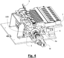
figure 4 is a further perspective view of the apparatus offigure 1 ; -
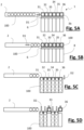
figures 5A - 5C are schematic views of the operating method of a device according to a possible embodiment of the present invention; -
figure 5D is a schematic view of the operating method of a device according to an embodiment alternative to that offigures 5A - 5C ; -
figures 6A - 6B are further schematic views of a device according to an embodiment alternative to that offigures 5A - 5C . - A
device 1 for movingcontainers 100 comprises afirst movement element 2 adapted to move containers along at least one row towards a distributingdrum 3. Typically, the first movement element precisely comprises one row ofcontainers 100. The possibility to have a greater number of rows is not however excluded, typically if thedrum 3 has large dimensions, such as to be able to receive more rows parallel to one another. In particular, feeding several rows would be advantageous if the radius of the drum section would be particularly large and thus the curvature of the drum section small, such as to be able to have several rows of seats, substantially at the same height, in the drum. As better described hereunder, the effect of the drum would anyhow stay unvaried, i.e. that of distributing the containers that were initially arranged in the same row along several rows. - The
containers 100 can have different shapes. Preferably, they have a closed body on the bottom and typically have on opening on top. Typically, the opening has a flange, although embodiments adapted to cooperate withcontainers 100 not provided with flanges are possible. Apreferred container 100 used with thepresent device 1 is a coffee capsule or a container having similar shape. - The
first movement element 2, shown only schematically infigures 5A - 5D , is known in the art and not discussed in detail herein. Typically, it is shaped like a conveyor belt, or an air channel, or a belt, etc. - In a known way, the
first movement element 2 typically receives thecontainers 100 from a source. - According to a possible aspect, the
device 1 can comprise an orientator element known in the art and not shown in detail in the figures and configured to arrange thecontainers 100 according to a predefined orientation inside thefirst movement element 2, typically with the cavity facing upward. - As discussed, a distributing
drum 3, henceforth also "drum 3," is present downstream of thefirst movement element 2. - The
drum 3 is rotatable around a rotation axis A. - Such rotation can occur by means of different methods known to the technician of the field.
- Preferably, the device has an electric motor M adapted to control a rotating
shaft 4 on which thedrum 3 is mounted. The rotatingshaft 4 can be controlled directly by the motor M or gears can act as reducers and are interposed between theshaft 4 and the motor M. - The
device 1 is configured such as thefirst movement element 2 feeds thecontainers 100 arranged along at least one row, along a first forward direction D1 axial with respect to the rotation axis A, i.e. parallel thereto and arranged at a distance from the rotation axis A. - In other words, axial does not mean that it coincides with the rotation axis A but that it is substantially parallel thereto, such as, when considering a plane orthogonal to the rotation axis A, such plane is substantially orthogonal also to the first
forward direction D 1. - According to a preferred aspect, the
drum 3 is provided with a plurality of radial teeth 3a. The space between successive teeth 3a (i.e. radially arranged in succession on the drum 3) forms seats 3b into which thecontainers 100 can be at least partially inserted. - As discussed, the
containers 100 are preferably provided with aflange 103 arranged at the upper portion thereof. The teeth 3a are typically arranged such as to be able to support the flange of thecontainers 100. Thus, the distance between two teeth 3a arranged successively in radial direction on thedrum 3 is preferably less than the diameter (or the greatest dimension) of the flange of thecontainer 100, such as, as discussed, thecontainers 100 can be supported by the respective flange within theseat 3b. - Embodiments wherein the containers can be leaned into the respective seats are anyhow possible. In such case, the device is typically shaped such as to support the
containers 100 on the bottom and such as to cooperate with a different portion of thecontainer 100, typically with its body, such as to allow it to be pull out of theseat 3b. Generally, the drum has a plurality of sectors 31 - 36 arranged in succession along the rotation axis A of thedrum 3. Each sector is provided with aseat 3b adapted to accommodate one or more containers, eachseat 3b is preferably configured to accommodate asingle container 100. - The number of sectors 31 - 36 can obviously vary in different embodiments and typically corresponds to the maximum number of rows along which the
containers 100 coming out of thedrum 3 can be organized. - The
seats 3b are typically arranged so that acontainer 100, when moving forward along the first forward direction D1, can cross thevarious seats 3b of thedrum 3 arranged in axial succession (with respect to the rotation axis A), until reaching the furthest seat along the forward direction D1 and which seat is still not stably occupied by acontainer 100. - The
device 1 is thus preferably configured so that thecontainers 100 can move forward along theseats 3b of the drum until allseats 3b are stably occupied by acontainer 100. Acontainer 100 stably occupies aseat 3b when it cannot move forward along the forward direction D1, since a blocking element (for example a wall of the device) is immediately present downstream of theseat 3b or afurther seat 3b is present and in which adifferent container 100, which cannot in turn move forward along the forward direction D1, since it is in turn blocked in its travel by a blocking element or by afurther container 100 in thesuccessive seat 3b, is present. - The
device 1 preferably comprises asensor 5 known in the art and adapted to detect the filling of allseats 3b by means of the containers. It is possible to provide a plurality of sensors 5 (for example one for each seat), or asingle sensor 5 adapted, for example, to detect the presence of acontainer 100 in thelast seat 3b, i.e. thelast seat 3b thecontainers 100 encounter during their travel along the first forward direction D1. Additionally or alternatively, it is possible to provide thedevice 1 with a sensor, for example a photocell, adapted to allow to count thecontainers 100 entering thedrum 3. - In fact, typically, the
containers 100 are fed into thedrum 3 continuously, thus, if a container reaches thelast seat 3b, the preceding seats are also occupied by containers. - According to different embodiments, the sectors 31 - 36 of the
drum 3 can be integral to one another when rotating, or at least part of the sectors 31 - 36 can rotate independently of the other sectors of thedrum 3. - According to the first solution schematized in
figures 5A - 5C , all the sectors 31-36 rotate synchronously, typically by means of the action of theshaft 4. - This way, all the
containers 100 present in theseats 3b are delivered from thedrum 3. - According to an alternative solution schematized for example in
figure 5D , the sectors 31 - 36 can be rotated around the rotation axis A independently of one another. - This way, it is possible to select which containers to deliver from the
drum 3. Typically, the containers arranged at a row that does not need to be filled at that time, for example because the machine arranged in series at thedevice 1 is not able to handle thecontainers 100 arranged at such row, are kept in thedrum 3. - It should be noted how such second solution can anyhow allow the synchronous rotation of all sectors and is thus able, if needed, to deliver all the
containers 100 that were fed to thedrum 3. - There are different possible methods of making an independent rotation between the various sectors 31 - 36 of the drum. A possible solution provides, for example, the use of mechanisms adapted to selectively constrain and release each sector 31 - 36 from the
shaft 4. - Generally, the rotation of the
drum 3 allows to move thecontainers 100 and, in particular, to deliversuch containers 100 along a second forward direction D2 substantially orthogonal to the rotation axis A, and thus to the first forward direction D1. - It should be noted how the
drum 3 is typically provided with an ejectingelement 6 for ejecting thecontainers 100 from thedrum 3 and in particular from therespective seats 3b. The interaction between such ejectingelement 6 and thecontainers 100 helps determine the second forward direction D2. - Preferably, the second forward direction D2 is substantially orthogonal to the first forward direction D1, at least until the ejecting
element 6 cooperates with thecontainers 100. - A preferred method of determining the relationship between the first forward direction D1 and the second forward direction D2 is that of considering a plan view of the
device 1 in use, i.e. a substantially horizontal plane arranged above thedevice 1 during use. By orthogonally projecting the first forward direction D1 and the second forward direction D2, it is possible to assess how such projections are substantially orthogonal to one another, thus preferably forming a 90° angle with a tolerance of less than 20°, preferably of less than 10°. - This way, the
containers 100 present in thedrum 3 are moved at a rotation thereof along a circular path having the rotation axis A as the center, since they rotate integrally with a portion of the drum r placed at a distance from the rotation axis A itself. Successively, they are delivered from thedrum 3 along the second forward direction D2. - It should be noted how the rotation integral with the
drum 3 can occur for a very limited angle, since it is possible that the containers are delivered by the container immediately after the movement thereof. - Preferably, the delivery of the containers starts with the interaction between the
containers 100 and the ejectingelement 6. - The movement of the
containers 100 on thedrum 3 is thus typically tangential to the rotation axis A until the intervention of the ejectingelement 6, thanks to which ejecting element the containers are moved along the second forward direction D2, as discussed above. - According to a possible aspect, the ejecting element comprises a plurality of
guides 6a adapted to come into contact with a portion of thecontainers 100, typically with the flange of thecontainers 100 when they are moved by thedrum 3. During the delivery of thecontainers 100 from thedrum 3, the containers can thus move forward along the guides pushed by thedrum 3, preferably by the teeth 3a of thedrum 3. According to a possible aspect, thedevice 1 comprises a separatingelement 7 adapted to modify and, in particular, increase the distance between thecontainers 100 measured in a direction axial to the rotation axis A, i.e. a direction parallel to such axis A. - In other words, at the separating
element 7, thecontainers 100 preferably move forward along third forward directions D3. At least part of such directions are divergent from one another, preferably considering the orthogonal projection of such third forward directions on the previously described horizontal plane. - According to a preferred aspect,
such separating element 7 comprises a plurality ofchannels 7a. At least part of thechannels 7a are arranged branching off from one another, such as to increase the transversal distance between thecontainers 100, i.e. the distance measured parallel to the rotation axis A of thedrum 3. - According to a possible aspect, the
device 1 has asecond movement element 8 adapted to move/transport thecontainers 100 downstream of thedrum 3, typically downstream of the separatingelement 7. - Such
second movement element 8 typically comprises a plurality of channels along which the containers can slide. Different movement elements, such as belt, air conveyed, etc., known in the art can be used as a second movement element. - Such
second movement element 8, shown only schematically infigures 5A - 5D , is configured such as to allow the forward movement of a plurality of containers along several rows, typically parallel to one another. - Alternative embodiments do not provide for the use of such
second movement element 8, for example allowing thecontainers 100 to be picked up directly downstream of thedrum 3 or anyhow downstream of the separatingelement 7. - In use, the
device 1 feeds, by means of thefirst movement element 2, a plurality ofcontainers 100 arranged along at least one row, to thedrum 3, typically precisely along a single row, by moving them along the first forward direction D1. - A number N of
containers 100 thus fills thedrum 3. - When the
drum 3 has reached the desired capacity ofcontainers 100, thus when thedrum 3 accommodates N containers arranged along a row, thedrum 3 is rotated. When thedrum 3 moves, thecontainers 100 are moved and delivered from the drum along the second forward direction D2, substantially orthogonally to the first forward direction D1. - According to a possible solution, all the sectors 31 - 36 of the
drum 3 move forward synchronously, such as to deliver all N containers along N rows. - The
drum 3 thus receivesN containers 100 along a row and the movement of the drum itself creates N rows of containers, each initially containing asingle container 100. Repeating the operations of thedrum 100 leads to filling the N rows of containers downstream of thedrum 3 with a plurality of containers for each row. In particular, after M filling and delivering cycles of thedrum 3, the device forms N rows ofcontainers 100 each provided withM containers 100, as schematized for example infigures 5A - 5C . - In such figures it is possible to observe how N is equal to 6. The drum thus receives 6 containers and after a number of 4 cycles for example (i.e. M = 4), the
device 1 is able to form 6 rows, each comprising 4 containers, starting from a condition in which the 24 containers were instead initially aligned along a single row. In particular, infigure 5C , the containers delivered in the preceding cycles are shown dotted. - In possible alternative solutions, in particular in those provided with sectors rotatable independently of one another, it is possible to fill the drum with
N containers 100. During the movement of the drum only part of the sectors is moved, thus X sectors are not rotated and do not thus deliver the respective containers. In such case, N - X rows of containers are formed. After M filling and delivery cycles, N - X rows of containers are formed, each containing M containers. - A similar solution is for example depicted in
figure 5D , in which it is possible to recognize how N is equal to 6, X is equal to 2 and M is equal to 4. - In a possible alternative solution, it is possible to distribute the containers among the rows in a different way. In other words, embodiments, in which each sector is always operated such as to deliver the respective container or is always operated such as to not deliver the respective container, are described.
- However, it is possible to control the
device 1 so as to vary the behavior of each single sector 31 - 36 of thedrum 6 over time. - For example, with reference to the embodiments of
figures 5A - 5D , it is for example possible to operate 3 cycles in which all 6 sectors deliver the respective container 100 (as infigure 5C ) and2 cycles in which only 4 sectors deliver the respective containers (as infigure 5D ). In such case, thedevice 1forms 6 rows of containers exiting thedrum - It should be noted how the description set forth herein makes it evident to the skilled person the use of the device when several rows of containers are fed to the drum contemporaneously.
- In particular, in the event of several feed rows, each row delivers N containers to the
drum 3. Following the rotation of the drum, N rows of containers are formed, each of the N rows exiting the drum containing a number of containers equal to the number of rows entering in the drum. - For example, as schematized in
figures 6A - 6B , the device could be configured to feed two rows of containers to thedrum 3 and, in particular, six containers from each of the two rows. Following the rotation of thedrum 3, six rows of containers are formed at the exit, each row containing two containers. By repeating the operations of the drum, it is possible to fill the rows coming out of thedrum 3 over time.
Claims (10)
- Device (1) for moving containers (100), comprising:• a first movement element (2) configured such as to move at least one row of containers (100);• a distributing drum (3) adapted to receive at least one row of objects (100) and to deliver the objects (100) of a same row in separate rows;wherein said distributing drum (3) is rotatable around a rotation axis (A) and is configured such as the entry of said containers (100) into said distributing drum (3) along the same row is carried out along a first forward direction (D1) substantially axial to the distributing drum (3) with respect to said rotation axis (A), and the delivery of the containers (100) initially arranged along the same row is carried out along several rows separated from one another along a second forward direction (D2) arranged substantially orthogonal to said first forward direction (D1).
- Device (1) according to claim 1, comprising a separating element (7) arranged downstream of said distributing drum (3) and adapted to modify the distance between said containers (100) downstream of said distributing drum (3), said distance being measured in a direction axial to the rotation axis of the distributing drum (3).
- Device (1) according to claim 2, wherein said separating element (7) comprises a plurality of channels (7a), at least part of said channels (7a) not being parallel to one another.
- Device (1) according to one of the preceding claims, wherein said distributing drum (3) comprises a plurality of sectors (31 - 36) arranged in series along said rotation axis (A), each sector (31 - 36) being able to accommodate one or more containers (100), preferably a single container (100).
- Device (1) according to claim 4, wherein said sectors (31 - 36) are integral to one another when rotating.
- Device according to claim 4, wherein at least part of said sectors (31 - 36) is rotatable independently of one another with respect to said rotation axis (A).
- Device (1) according to claim 6, wherein said distributing drum (3) is rotated by a shaft (4), at least part of said sectors (31 - 36) being selectively constrainable to, and releasable from, said shaft (4).
- Device (1) according to one of the preceding claims, comprising a sensor (5) arranged at said distributing drum (3) and adapted to detect the presence of the containers (100) at the distributing drum (3).
- Device (1) according to one of the preceding claims, comprising a second movement element (8) arranged downstream of said distributing drum (3) and adapted to receive a plurality of rows of containers (100) from said distributing drum (3).
- Process for moving containers (100) by means of a device (1) according to one or more of the preceding claims, comprising the steps of:i. moving the containers (100) along a first movement element (2);ii. delivering at least one row of containers (100) to said distributing drum (3) along a first forward direction (D1) axial with respect to the distributing drum (3);iii. rotating said distributing drumiv. delivering from said drum, in a plurality of rows, said containers initially arranged along the same row, along a second forward direction (D2) substantially perpendicular to the first forward direction (D1).
Applications Claiming Priority (1)
| Application Number | Priority Date | Filing Date | Title |
|---|---|---|---|
| IT202100030596 | 2021-12-02 |
Publications (1)
| Publication Number | Publication Date |
|---|---|
| EP4190727A1 true EP4190727A1 (en) | 2023-06-07 |
Family
ID=80933816
Family Applications (1)
| Application Number | Title | Priority Date | Filing Date |
|---|---|---|---|
| EP22211070.2A Withdrawn EP4190727A1 (en) | 2021-12-02 | 2022-12-02 | Device for moving containers |
Country Status (1)
| Country | Link |
|---|---|
| EP (1) | EP4190727A1 (en) |
Citations (2)
| Publication number | Priority date | Publication date | Assignee | Title |
|---|---|---|---|---|
| US4164997A (en) * | 1977-02-02 | 1979-08-21 | Owens-Illinois, Inc. | Article transport device and method |
| EP2412645A1 (en) * | 2010-07-28 | 2012-02-01 | Samar Technologies Ltd. | Pre-filled infusion capsule, associated manufacturing method and device |
-
2022
- 2022-12-02 EP EP22211070.2A patent/EP4190727A1/en not_active Withdrawn
Patent Citations (2)
| Publication number | Priority date | Publication date | Assignee | Title |
|---|---|---|---|---|
| US4164997A (en) * | 1977-02-02 | 1979-08-21 | Owens-Illinois, Inc. | Article transport device and method |
| EP2412645A1 (en) * | 2010-07-28 | 2012-02-01 | Samar Technologies Ltd. | Pre-filled infusion capsule, associated manufacturing method and device |
Similar Documents
| Publication | Publication Date | Title |
|---|---|---|
| US6799413B2 (en) | Apparatus and methods for filling containers with pills | |
| US9409724B2 (en) | Device and method for conveying lumpy products | |
| US8701865B2 (en) | Unscrambling machine for containers and relative process | |
| US10104898B2 (en) | Apparatus and method for transferring and placing collated sausage links into a packaging item | |
| US20130001044A1 (en) | Bottle Feed Station | |
| US7281361B2 (en) | Method of article portioning | |
| JP6736064B2 (en) | Drug feeder | |
| US3090476A (en) | Bobbin handling arrangement | |
| US20040016622A1 (en) | Method and device for supplying regularly objects to a work station | |
| US8770381B2 (en) | Bread conveying apparatus and bread packaging system | |
| CN107108131B (en) | Apparatus and method for reliably supplying compliant closure elements | |
| KR20180056633A (en) | Drug delivery canisters used in automated drug delivery devices | |
| EP4190727A1 (en) | Device for moving containers | |
| EP2079651A1 (en) | Apparatus for unscrambling and orienting preforms or objects in general | |
| JP7387959B2 (en) | Conveying device and method for conveying tampon applicators | |
| EP3315434B1 (en) | System for feeding objects to a multi-entrance work group | |
| JP2023535113A (en) | supply unit for goods | |
| US12552568B2 (en) | Tablet dispensing apparatus and method | |
| EP4408373B1 (en) | Device and method for feeding capsules | |
| EP3935611B1 (en) | Conveying device of products for automatic dispensers | |
| JP2023537174A (en) | supply unit for goods | |
| HK40101615A (en) | Conveying device and method for conveying tampon applicators |
Legal Events
| Date | Code | Title | Description |
|---|---|---|---|
| PUAI | Public reference made under article 153(3) epc to a published international application that has entered the european phase |
Free format text: ORIGINAL CODE: 0009012 |
|
| STAA | Information on the status of an ep patent application or granted ep patent |
Free format text: STATUS: THE APPLICATION HAS BEEN PUBLISHED |
|
| AK | Designated contracting states |
Kind code of ref document: A1 Designated state(s): AL AT BE BG CH CY CZ DE DK EE ES FI FR GB GR HR HU IE IS IT LI LT LU LV MC ME MK MT NL NO PL PT RO RS SE SI SK SM TR |
|
| STAA | Information on the status of an ep patent application or granted ep patent |
Free format text: STATUS: THE APPLICATION IS DEEMED TO BE WITHDRAWN |
|
| 18D | Application deemed to be withdrawn |
Effective date: 20231208 |