EP4190703A1 - Modular proximity sensing in atmospheric suit - Google Patents
Modular proximity sensing in atmospheric suit Download PDFInfo
- Publication number
- EP4190703A1 EP4190703A1 EP22210945.6A EP22210945A EP4190703A1 EP 4190703 A1 EP4190703 A1 EP 4190703A1 EP 22210945 A EP22210945 A EP 22210945A EP 4190703 A1 EP4190703 A1 EP 4190703A1
- Authority
- EP
- European Patent Office
- Prior art keywords
- suit
- atmospheric
- processing circuitry
- distance
- proximity sensors
- Prior art date
- Legal status (The legal status is an assumption and is not a legal conclusion. Google has not performed a legal analysis and makes no representation as to the accuracy of the status listed.)
- Pending
Links
Images


Classifications
-
- B—PERFORMING OPERATIONS; TRANSPORTING
- B64—AIRCRAFT; AVIATION; COSMONAUTICS
- B64G—COSMONAUTICS; VEHICLES OR EQUIPMENT THEREFOR
- B64G6/00—Space suits
-
- G—PHYSICS
- G08—SIGNALLING
- G08B—SIGNALLING SYSTEMS, e.g. PERSONAL CALLING SYSTEMS; ORDER TELEGRAPHS; ALARM SYSTEMS
- G08B7/00—Signalling systems according to two or more of groups G08B3/00 - G08B6/00
- G08B7/06—Signalling systems according to two or more of groups G08B3/00 - G08B6/00 using electric transmission, e.g. involving audible and visible signalling through the use of sound and light sources
-
- G—PHYSICS
- G01—MEASURING; TESTING
- G01S—RADIO DIRECTION-FINDING; RADIO NAVIGATION; DETERMINING DISTANCE OR VELOCITY BY USE OF RADIO WAVES; LOCATING OR PRESENCE-DETECTING BY USE OF THE REFLECTION OR RERADIATION OF RADIO WAVES; ANALOGOUS ARRANGEMENTS USING OTHER WAVES
- G01S13/00—Systems using the reflection or reradiation of radio waves, e.g. radar systems; Analogous systems using reflection or reradiation of waves whose nature or wavelength is irrelevant or unspecified
- G01S13/02—Systems using reflection of radio waves, e.g. primary radar systems; Analogous systems
- G01S13/06—Systems determining position data of a target
- G01S13/08—Systems for measuring distance only
-
- G—PHYSICS
- G08—SIGNALLING
- G08B—SIGNALLING SYSTEMS, e.g. PERSONAL CALLING SYSTEMS; ORDER TELEGRAPHS; ALARM SYSTEMS
- G08B21/00—Alarms responsive to a single specified undesired or abnormal condition and not otherwise provided for
- G08B21/18—Status alarms
- G08B21/182—Level alarms, e.g. alarms responsive to variables exceeding a threshold
Definitions
- Exemplary embodiments pertain to the art of atmospheric suits and, in particular, to modular proximity sensing in an atmospheric suit.
- an atmospheric suit is used not only for protection against impacts but also to maintain a habitable environment.
- an atmospheric suit referred to as an extravehicular mobility unit (EMU), for example, includes a helmet and full body suit supplied by an oxygen tank that are essential for maintaining an environment that sustains the astronaut. Rupture of or damage to the atmospheric suit resulting in pressure loss or exposure to the atmosphere can create a life-threatening situation for the astronaut.
- EMU extravehicular mobility unit
- a system for an atmospheric suit includes one or more modular proximity sensors affixed to corresponding one or more portions of the atmospheric suit. Each of the one or more proximity sensors provides a distance to a nearest object from the corresponding portion of the atmospheric suit.
- the system also includes processing circuitry configured to obtain the distance from each of the one or more proximity sensors to the nearest object and to provide information to the wearer of the atmospheric suit.
- each of the one or more proximity sensors obtains the distance to the nearest object periodically.
- the processing circuitry provides the information based on the distance from one or more of the one or more proximity sensors being at or below a threshold distance.
- the processing circuitry obtains the threshold distance as an input from a wearer of the atmospheric suit.
- the processing circuitry provides the information as an audible alarm through one or more speakers in a helmet of the atmospheric suit.
- the processing circuitry provides the information as a haptic output.
- the processing circuitry provides the information as a visual alarm based on light emitting diodes co-located with the one or more of the one or more proximity sensors.
- the processing circuitry provides the information as an alert on a display in a helmet of the atmospheric suit.
- the processing circuitry obtains a request for a distance from one of the one or more proximity sensors as an input from a wearer of the atmospheric suit and to trigger the one or the one or more proximity sensors to obtain the distance based on the request.
- the processing circuitry provides the distance from the one of the one or more proximity sensors as the information on a display or audibly via a speaker in a helmet of the atmospheric suit.
- a method of assembling a system for an atmospheric suit includes affixing one or more modular proximity sensors to corresponding one or more portions of the atmospheric suit. Each of the one or more proximity sensors provides a distance to a nearest object from the corresponding portion of the atmospheric suit. The method also includes configuring processing circuitry to obtain the distance from each of the one or more proximity sensors to the nearest object and to provide information to the wearer of the atmospheric suit.
- the configuring the processing circuitry includes the processing circuitry obtaining the distance to the nearest object periodically.
- the configuring the processing circuitry includes the processing circuitry providing the information based on the distance from one or more of the one or more proximity sensors being at or below a threshold distance.
- the configuring the processing circuitry includes the processing circuitry obtaining the threshold distance as an input from a wearer of the atmospheric suit.
- the configuring the processing circuitry includes the processing circuitry providing the information as an audible alarm through one or more speakers in a helmet of the atmospheric suit.
- the configuring the processing circuitry includes the processing circuitry providing the information as a haptic output.
- the configuring the processing circuitry includes the processing circuitry providing the information as a visual alarm based on light emitting diodes co-located with the one or more of the one or more proximity sensors.
- the configuring the processing circuitry includes the processing circuitry providing the information as an alert on a display in a helmet of the atmospheric suit.
- the configuring the processing circuitry includes the processing circuitry obtaining a request for a distance from one of the one or more proximity sensors as an input from a wearer of the atmospheric suit and to trigger the one or the one or more proximity sensors to obtain the distance based on the request.
- the configuring the processing circuitry includes the processing circuitry providing the distance from the one of the one or more proximity sensors as the information on a display or audibly via a speaker in a helmet of the atmospheric suit.
- an atmospheric suit e.g., space suit
- the atmospheric suit facilitates exploration and operation in otherwise-inhospitable settings.
- damage or rupture of the atmospheric suit can create a hazardous condition for the wearer.
- a wearer e.g., astronaut in a space suit
- a particular maneuver e.g., backing up
- Embodiments of the systems and methods detailed herein relate to modular proximity sensing in an atmospheric suit.
- One or more proximity sensors are attached to parts of the atmospheric suit to determine a distance from those parts to a surface.
- Modularity refers to the fact that the proximity sensors may be moved to different parts of the atmospheric suit based on a particular anticipated scenario, for example.
- the atmospheric suit refers to not only the helmet and full body suit but also to the life support system and communication system attached thereto.
- the EMU along with a primary life support system (PLSS) and a display and control module (DCM) are referred to as an atmospheric suit.
- PLSS primary life support system
- DCM display and control module
- applications for the proximity sensing according to one or more embodiments also include underwater (e.g., in an atmospheric diving suit), earth-based (e.g., in a hazmat suit or contamination suit), high-altitude (e.g., in a flight suit), and sub-surface environments.
- any suit that includes the helmet to maintain a habitable environment and attachments to provide life support and communication is referred to as an atmospheric suit.
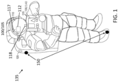
- FIG. 1 shows an atmospheric suit 100 with a proximity sensing system 135 according to one or more embodiments.
- the exemplary atmospheric suit 100 shown in FIG. 1 is an EMU 105 that includes a helmet 110, full-body suit 115 that includes boots, PLSS 120, and DCM 130. A display 112 and a speaker 117 are indicated within the helmet 110. These are further discussed with reference to FIG. 2 .
- the processing circuitry 140 of the proximity sensing system 135 may be part of our coupled to the existing components of the DCM 130.
- the processing circuitry 140 separately or through the DCM 130, may include one or more processors and memory.
- the proximity sensing system 135 also includes one or more proximity sensors 150 that are modular (i.e., repositionable) and communicate with the processing circuitry 140. Each proximity sensor 150 may be affixed to a portion of the atmospheric suit 100 and may be positioned to obtain the distance from that portion to a closest object 210 to the portion.
- the proximity sensors 150 may be known devises that provide a distance to the closest object 210 ( FIG. 2 ), and different proximity sensors 150 may be of different types.
- An exemplary proximity sensor 150 is an optical proximity sensor (e.g., lidar system) that transmits incident light and detects a reflection of the incident light from an object 210.
- Another exemplary proximity sensor 150 is a capacitive proximity sensor that detects distance to the closest object 210 based on a change in its capacitance due to the object 210.
- Yet other exemplary proximity sensors 150 include a magnetic proximity sensor that detects a magnetic field of a magnetic object 210 and an ultrasonic proximity sensor that emits an ultrasonic pulse (i.e., sound wave) and detects the reflection of that emitted pulse.
- Different proximity sensors 150 may be employed based on the environment (e.g., ultrasonic proximity sensor may be impractical in the vacuum of space).
- FIG. 2 illustrates an exemplary scenario for the atmospheric suit 100 with the proximity sensing system 135 according to one or more embodiments.
- the wearer of the atmospheric suit 100 e.g., an EMU 105
- the cave wall 220 is the object 210 that is nearest to the proximity sensors 150 that are distributed at different portions of the atmospheric suit 100.
- the portions of the atmospheric suit 100 to which the modular proximity sensors 150 are affixed may be changed.
- the left side of the atmospheric suit 100 is closer to the wall 220 than the right.
- the proximity sensors 150 may be used to determine that the wearer should move to the right rather than farther to the left.
- one or more types of information may be provided in one or more ways based on the proximity sensors 150 and the processing circuitry 140.
- the processing circuitry 140 is aware of the portion of the atmospheric suit 100 to which each proximity sensor 150 is affixed.
- the processing circuitry 140 may provide input to the display 112 and the speaker 117 and may obtain user inputs via the microphone 118 or DCM 130, for example.
- the processing circuitry 140 may additionally obtain information via gestures or any other known input mechanism.
- the input from the wearer may indicate a request for the distance obtained by a particular proximity sensor 150 corresponding with a particular portion of the atmospheric suit 100, for example. This inquiry may trigger the particular proximity sensor 150, via the processing circuitry, to obtain a distance measurement.
- the processing circuitry 140 may map each proximity sensor 150 to the corresponding portion of the atmospheric suit. Thus, a wearer inquiry about the distance from the left shoulder to a wall 220 may be mapped by the processing circuitry 140 to the particular proximity sensor 150 that is affixed to the left shoulder of the atmospheric suit.
- the information provided by the processing circuitry may be a distance value.
- the input from the wearer may indicate a threshold distance. In this case, each proximity sensor 150 may obtain the distance to the closest object 210 periodically and the information provided by the processing circuitry 140 may be an alert when any proximity sensor 150 obtains a distance below the threshold distance.
- information may be provided by the processing circuitry 140 in one or more ways.
- An alert or distance may be displayed on the display 112 or audibly indicated via the speaker 117.
- the exemplary illustration of one speaker 117 is not intended to preclude alternate or additional arrangements.
- an array of speakers 117 may be used to provide directional audio output (e.g., alarm from the speaker in the direction corresponding to the proximity sensor 150 that obtained a distance to the object 210 that is below the threshold distance). Additional ways of providing information or alerts are discussed with reference to FIGS. 3 and 4 .
- FIG. 3 shows a portion of the atmospheric suit 100 with a proximity sensor 150 according to an exemplary embodiment.
- a feedback device 310 is shown corresponding with the proximity sensor 150.
- the proximity sensor 150 may be on an outer surface of the atmospheric suit 100 while the feedback device 310 is on an inner surface of the atmospheric suit 100.
- the feedback device 310 may be adhered within the atmospheric suit 100 (e.g., adhered to the wearer prior to donning the atmospheric suit 100) according to alternate embodiments.
- the exemplary feedback device 310 in FIG. 3 may be a piezo haptic device 320.
- the haptic device 330 may vibrate to indicate to the wearer that the corresponding portion of the atmospheric suit 100 is too close to an object 210.
- the haptic device 320 may be actuated by the processing circuitry 140 that obtains the distance from the proximity sensor 150.
- the processing circuitry 140 may control a pattern of the haptic output. For example, the vibration frequency may increase as the distance decreases below the threshold distance.
- FIG. 4 shows a portion of the atmospheric suit 100 with a proximity sensor 150 according to an exemplary embodiment.
- the exemplary feedback device 310 may be one or an array of light emitting diodes (LEDs) 410. As shown, LEDs 410 may be arranged in the helmet 110 and the position of each LED 410 may correspond with an associated proximity sensor 150. For example, a proximity sensor 150 on the left shoulder of the atmospheric suit 100 may correspond with an LED 410 on the left side of the helmet 110. Alternately, the array of LED 410 may be co-located with the proximity sensor 150 on the outer surface of the atmospheric suit 100, as shown.
- LEDs light emitting diodes
- the processing circuitry 140 may map each proximity sensor 150 to a particular one or array of LEDs 410 and may actuate the LED 410 based on the distance detected by the proximity sensor 150.
- the color indicated by the array of LEDs 410 may be controlled by the processing circuitry 140 based on distance (e.g., yellow when the distance is 6 inches from the threshold distance, red when the distance is at or below the threshold distance).
- the LED 410 on the outer surface of the atmospheric suit 100 may be used when multiple astronauts are navigating a space together.
Landscapes
- Engineering & Computer Science (AREA)
- Remote Sensing (AREA)
- Radar, Positioning & Navigation (AREA)
- Physics & Mathematics (AREA)
- General Physics & Mathematics (AREA)
- Computer Networks & Wireless Communication (AREA)
- Aviation & Aerospace Engineering (AREA)
- Length Measuring Devices With Unspecified Measuring Means (AREA)
- Helmets And Other Head Coverings (AREA)
Abstract
Description
- Exemplary embodiments pertain to the art of atmospheric suits and, in particular, to modular proximity sensing in an atmospheric suit.
- In some environments and applications, an atmospheric suit is used not only for protection against impacts but also to maintain a habitable environment. In a space application, an atmospheric suit referred to as an extravehicular mobility unit (EMU), for example, includes a helmet and full body suit supplied by an oxygen tank that are essential for maintaining an environment that sustains the astronaut. Rupture of or damage to the atmospheric suit resulting in pressure loss or exposure to the atmosphere can create a life-threatening situation for the astronaut.
- In one exemplary embodiment, a system for an atmospheric suit includes one or more modular proximity sensors affixed to corresponding one or more portions of the atmospheric suit. Each of the one or more proximity sensors provides a distance to a nearest object from the corresponding portion of the atmospheric suit. The system also includes processing circuitry configured to obtain the distance from each of the one or more proximity sensors to the nearest object and to provide information to the wearer of the atmospheric suit.
- In addition to one or more of the features described herein, each of the one or more proximity sensors obtains the distance to the nearest object periodically.
- In addition to one or more of the features described herein, the processing circuitry provides the information based on the distance from one or more of the one or more proximity sensors being at or below a threshold distance.
- In addition to one or more of the features described herein, the processing circuitry obtains the threshold distance as an input from a wearer of the atmospheric suit.
- In addition to one or more of the features described herein, the processing circuitry provides the information as an audible alarm through one or more speakers in a helmet of the atmospheric suit.
- In addition to one or more of the features described herein, the processing circuitry provides the information as a haptic output.
- In addition to one or more of the features described herein, the processing circuitry provides the information as a visual alarm based on light emitting diodes co-located with the one or more of the one or more proximity sensors.
- In addition to one or more of the features described herein, the processing circuitry provides the information as an alert on a display in a helmet of the atmospheric suit.
- In addition to one or more of the features described herein, the processing circuitry obtains a request for a distance from one of the one or more proximity sensors as an input from a wearer of the atmospheric suit and to trigger the one or the one or more proximity sensors to obtain the distance based on the request.
- In addition to one or more of the features described herein, the processing circuitry provides the distance from the one of the one or more proximity sensors as the information on a display or audibly via a speaker in a helmet of the atmospheric suit.
- In another exemplary embodiment, a method of assembling a system for an atmospheric suit includes affixing one or more modular proximity sensors to corresponding one or more portions of the atmospheric suit. Each of the one or more proximity sensors provides a distance to a nearest object from the corresponding portion of the atmospheric suit. The method also includes configuring processing circuitry to obtain the distance from each of the one or more proximity sensors to the nearest object and to provide information to the wearer of the atmospheric suit.
- In addition to one or more of the features described herein, the configuring the processing circuitry includes the processing circuitry obtaining the distance to the nearest object periodically.
- In addition to one or more of the features described herein, the configuring the processing circuitry includes the processing circuitry providing the information based on the distance from one or more of the one or more proximity sensors being at or below a threshold distance.
- In addition to one or more of the features described herein, the configuring the processing circuitry includes the processing circuitry obtaining the threshold distance as an input from a wearer of the atmospheric suit.
- In addition to one or more of the features described herein, the configuring the processing circuitry includes the processing circuitry providing the information as an audible alarm through one or more speakers in a helmet of the atmospheric suit.
- In addition to one or more of the features described herein, the configuring the processing circuitry includes the processing circuitry providing the information as a haptic output.
- In addition to one or more of the features described herein, the configuring the processing circuitry includes the processing circuitry providing the information as a visual alarm based on light emitting diodes co-located with the one or more of the one or more proximity sensors.
- In addition to one or more of the features described herein, the configuring the processing circuitry includes the processing circuitry providing the information as an alert on a display in a helmet of the atmospheric suit.
- In addition to one or more of the features described herein, the configuring the processing circuitry includes the processing circuitry obtaining a request for a distance from one of the one or more proximity sensors as an input from a wearer of the atmospheric suit and to trigger the one or the one or more proximity sensors to obtain the distance based on the request.
- In addition to one or more of the features described herein, the configuring the processing circuitry includes the processing circuitry providing the distance from the one of the one or more proximity sensors as the information on a display or audibly via a speaker in a helmet of the atmospheric suit.
- The following descriptions should not be considered limiting in any way. With reference to the accompanying drawings, like elements are numbered alike:
-
FIG. 1 shows an atmospheric suit with a proximity sensing system according to one or more embodiments; -
FIG. 2 illustrates an exemplary scenario for the atmospheric suit with the proximity sensing system according to one or more embodiments; -
FIG. 3 shows a portion of the atmospheric suit with a proximity sensor according to an exemplary embodiment; and -
FIG. 4 shows a portion of the atmospheric suit with a proximity sensor according to another exemplary embodiment. - A detailed description of one or more embodiments of the disclosed apparatus and method are presented herein by way of exemplification and not limitation with reference to the Figures.
- As previously noted, an atmospheric suit (e.g., space suit) creates a habitable environment for the wearer. Thus, the atmospheric suit facilitates exploration and operation in otherwise-inhospitable settings. As also noted, damage or rupture of the atmospheric suit can create a hazardous condition for the wearer. When a wearer (e.g., astronaut in a space suit) cannot see potential hazards because of low visibility or a particular maneuver (e.g., backing up), the potential for damage to the atmospheric suit by impacting a hard surface is increased.
- Embodiments of the systems and methods detailed herein relate to modular proximity sensing in an atmospheric suit. One or more proximity sensors are attached to parts of the atmospheric suit to determine a distance from those parts to a surface. Modularity refers to the fact that the proximity sensors may be moved to different parts of the atmospheric suit based on a particular anticipated scenario, for example. For ease of discussion, the atmospheric suit refers to not only the helmet and full body suit but also to the life support system and communication system attached thereto.
- Thus, in the exemplary space application, the EMU along with a primary life support system (PLSS) and a display and control module (DCM) are referred to as an atmospheric suit. While an EMU and a space application are specifically discussed for explanatory purposes, applications for the proximity sensing according to one or more embodiments also include underwater (e.g., in an atmospheric diving suit), earth-based (e.g., in a hazmat suit or contamination suit), high-altitude (e.g., in a flight suit), and sub-surface environments. Generally, any suit that includes the helmet to maintain a habitable environment and attachments to provide life support and communication is referred to as an atmospheric suit.
-
FIG. 1 shows anatmospheric suit 100 with aproximity sensing system 135 according to one or more embodiments. The exemplaryatmospheric suit 100 shown inFIG. 1 is an EMU 105 that includes ahelmet 110, full-body suit 115 that includes boots,PLSS 120, and DCM 130. Adisplay 112 and a speaker 117 are indicated within thehelmet 110. These are further discussed with reference toFIG. 2 . The processing circuitry 140 of theproximity sensing system 135 may be part of our coupled to the existing components of the DCM 130. The processing circuitry 140, separately or through the DCM 130, may include one or more processors and memory. Theproximity sensing system 135 also includes one ormore proximity sensors 150 that are modular (i.e., repositionable) and communicate with the processing circuitry 140. Eachproximity sensor 150 may be affixed to a portion of theatmospheric suit 100 and may be positioned to obtain the distance from that portion to a closest object 210 to the portion. - The
proximity sensors 150 may be known devises that provide a distance to the closest object 210 (FIG. 2 ), anddifferent proximity sensors 150 may be of different types. Anexemplary proximity sensor 150 is an optical proximity sensor (e.g., lidar system) that transmits incident light and detects a reflection of the incident light from an object 210. Anotherexemplary proximity sensor 150 is a capacitive proximity sensor that detects distance to the closest object 210 based on a change in its capacitance due to the object 210. Yet otherexemplary proximity sensors 150 include a magnetic proximity sensor that detects a magnetic field of a magnetic object 210 and an ultrasonic proximity sensor that emits an ultrasonic pulse (i.e., sound wave) and detects the reflection of that emitted pulse.Different proximity sensors 150 may be employed based on the environment (e.g., ultrasonic proximity sensor may be impractical in the vacuum of space). -
FIG. 2 illustrates an exemplary scenario for theatmospheric suit 100 with theproximity sensing system 135 according to one or more embodiments. The wearer of the atmospheric suit 100 (e.g., an EMU 105) is exploring a cave, as indicated. Thus, the cave wall 220 is the object 210 that is nearest to theproximity sensors 150 that are distributed at different portions of theatmospheric suit 100. In other scenarios, the portions of theatmospheric suit 100 to which themodular proximity sensors 150 are affixed may be changed. AsFIG. 2 illustrates, the left side of theatmospheric suit 100 is closer to the wall 220 than the right. If the wearer of theatmospheric suit 100 has low visibility and cannot ascertain the distance to the walls 220 on each side, theproximity sensors 150 may be used to determine that the wearer should move to the right rather than farther to the left. As detailed, one or more types of information may be provided in one or more ways based on theproximity sensors 150 and the processing circuitry 140. The processing circuitry 140 is aware of the portion of theatmospheric suit 100 to which eachproximity sensor 150 is affixed. The processing circuitry 140 may provide input to thedisplay 112 and the speaker 117 and may obtain user inputs via themicrophone 118 or DCM 130, for example. The processing circuitry 140 may additionally obtain information via gestures or any other known input mechanism. - The input from the wearer may indicate a request for the distance obtained by a
particular proximity sensor 150 corresponding with a particular portion of theatmospheric suit 100, for example. This inquiry may trigger theparticular proximity sensor 150, via the processing circuitry, to obtain a distance measurement. According to an exemplary embodiment, the processing circuitry 140 may map eachproximity sensor 150 to the corresponding portion of the atmospheric suit. Thus, a wearer inquiry about the distance from the left shoulder to a wall 220 may be mapped by the processing circuitry 140 to theparticular proximity sensor 150 that is affixed to the left shoulder of the atmospheric suit. In this case, the information provided by the processing circuitry may be a distance value. As another example, the input from the wearer may indicate a threshold distance. In this case, eachproximity sensor 150 may obtain the distance to the closest object 210 periodically and the information provided by the processing circuitry 140 may be an alert when anyproximity sensor 150 obtains a distance below the threshold distance. - As previously noted, information may be provided by the processing circuitry 140 in one or more ways. An alert or distance may be displayed on the
display 112 or audibly indicated via the speaker 117. The exemplary illustration of one speaker 117 is not intended to preclude alternate or additional arrangements. For example, an array of speakers 117 may be used to provide directional audio output (e.g., alarm from the speaker in the direction corresponding to theproximity sensor 150 that obtained a distance to the object 210 that is below the threshold distance). Additional ways of providing information or alerts are discussed with reference toFIGS. 3 and 4 . -
FIG. 3 shows a portion of theatmospheric suit 100 with aproximity sensor 150 according to an exemplary embodiment. A feedback device 310 is shown corresponding with theproximity sensor 150. As shown, theproximity sensor 150 may be on an outer surface of theatmospheric suit 100 while the feedback device 310 is on an inner surface of theatmospheric suit 100. The feedback device 310 may be adhered within the atmospheric suit 100 (e.g., adhered to the wearer prior to donning the atmospheric suit 100) according to alternate embodiments. The exemplary feedback device 310 inFIG. 3 may be a piezo haptic device 320. When the closest object 210 to theproximity sensor 150 is less than a threshold distance that is predefined or set based on input from the wearer, the haptic device 330 may vibrate to indicate to the wearer that the corresponding portion of theatmospheric suit 100 is too close to an object 210. The haptic device 320 may be actuated by the processing circuitry 140 that obtains the distance from theproximity sensor 150. The processing circuitry 140 may control a pattern of the haptic output. For example, the vibration frequency may increase as the distance decreases below the threshold distance. -
FIG. 4 shows a portion of theatmospheric suit 100 with aproximity sensor 150 according to an exemplary embodiment. The exemplary feedback device 310 may be one or an array of light emitting diodes (LEDs) 410. As shown, LEDs 410 may be arranged in thehelmet 110 and the position of each LED 410 may correspond with an associatedproximity sensor 150. For example, aproximity sensor 150 on the left shoulder of theatmospheric suit 100 may correspond with an LED 410 on the left side of thehelmet 110. Alternately, the array of LED 410 may be co-located with theproximity sensor 150 on the outer surface of theatmospheric suit 100, as shown. The processing circuitry 140 may map eachproximity sensor 150 to a particular one or array of LEDs 410 and may actuate the LED 410 based on the distance detected by theproximity sensor 150. The color indicated by the array of LEDs 410 may be controlled by the processing circuitry 140 based on distance (e.g., yellow when the distance is 6 inches from the threshold distance, red when the distance is at or below the threshold distance). The LED 410 on the outer surface of theatmospheric suit 100 may be used when multiple astronauts are navigating a space together. - The term "about" is intended to include the degree of error associated with measurement of the particular quantity based upon the equipment available at the time of filing the application.
- The terminology used herein is for the purpose of describing particular embodiments only and is not intended to be limiting of the present disclosure. As used herein, the singular forms "a", "an" and "the" are intended to include the plural forms as well, unless the context clearly indicates otherwise. It will be further understood that the terms "comprises" and/or "comprising," when used in this specification, specify the presence of stated features, integers, steps, operations, elements, and/or components, but do not preclude the presence or addition of one or more other features, integers, steps, operations, element components, and/or groups thereof.
- While the present disclosure has been described with reference to an exemplary embodiment or embodiments, it will be understood by those skilled in the art that various changes may be made and equivalents may be substituted for elements thereof without departing from the scope of the present disclosure. In addition, many modifications may be made to adapt a particular situation or material to the teachings of the present disclosure without departing from the essential scope thereof. Therefore, it is intended that the present disclosure not be limited to the particular embodiment disclosed as the best mode contemplated for carrying out this present disclosure, but that the present disclosure will include all embodiments falling within the scope of the claims.
Claims (15)
Applications Claiming Priority (1)
| Application Number | Priority Date | Filing Date | Title |
|---|---|---|---|
| US17/540,811 US11908312B2 (en) | 2021-12-02 | 2021-12-02 | Modular proximity sensing in atmospheric suit |
Publications (1)
| Publication Number | Publication Date |
|---|---|
| EP4190703A1 true EP4190703A1 (en) | 2023-06-07 |
Family
ID=84370636
Family Applications (1)
| Application Number | Title | Priority Date | Filing Date |
|---|---|---|---|
| EP22210945.6A Pending EP4190703A1 (en) | 2021-12-02 | 2022-12-01 | Modular proximity sensing in atmospheric suit |
Country Status (2)
| Country | Link |
|---|---|
| US (1) | US11908312B2 (en) |
| EP (1) | EP4190703A1 (en) |
Citations (3)
| Publication number | Priority date | Publication date | Assignee | Title |
|---|---|---|---|---|
| WO2015147625A1 (en) * | 2014-03-24 | 2015-10-01 | Calva Mendez Diana Elizabeth | Illumination, communication and information display system for suits used in extreme environments |
| US10499693B2 (en) * | 2016-06-16 | 2019-12-10 | Elwha Llc | Selectively stiffenable assemblies, protective garments for protecting an individual, and systems and methods of using the same |
| US20210354858A1 (en) * | 2020-05-12 | 2021-11-18 | Hamilton Sundstrand Corporation | Atmospheric suit with integrated fiber optic sensing network |
Family Cites Families (5)
| Publication number | Priority date | Publication date | Assignee | Title |
|---|---|---|---|---|
| US9072941B2 (en) | 2011-08-11 | 2015-07-07 | The Charles Stark Draper Laboratory, Inc. | Exoskeleton suit for adaptive resistance to movement |
| US9741215B2 (en) * | 2014-12-11 | 2017-08-22 | Elwha Llc | Wearable haptic feedback devices and methods of fabricating wearable haptic feedback devices |
| US10257434B2 (en) * | 2015-08-31 | 2019-04-09 | Daniel Arnold | Multiview body camera system with environmental sensors and alert features |
| US20200326537A1 (en) | 2019-04-11 | 2020-10-15 | Hypergiant Industries, Inc. | Gesture control of heads-up display |
| US20210223557A1 (en) * | 2019-08-21 | 2021-07-22 | Hypergiant Industries, Inc. | Active display helmet |
-
2021
- 2021-12-02 US US17/540,811 patent/US11908312B2/en active Active
-
2022
- 2022-12-01 EP EP22210945.6A patent/EP4190703A1/en active Pending
Patent Citations (3)
| Publication number | Priority date | Publication date | Assignee | Title |
|---|---|---|---|---|
| WO2015147625A1 (en) * | 2014-03-24 | 2015-10-01 | Calva Mendez Diana Elizabeth | Illumination, communication and information display system for suits used in extreme environments |
| US10499693B2 (en) * | 2016-06-16 | 2019-12-10 | Elwha Llc | Selectively stiffenable assemblies, protective garments for protecting an individual, and systems and methods of using the same |
| US20210354858A1 (en) * | 2020-05-12 | 2021-11-18 | Hamilton Sundstrand Corporation | Atmospheric suit with integrated fiber optic sensing network |
Non-Patent Citations (1)
| Title |
|---|
| LOFLIN BENJAMIN ET AL: "Identification of shoulder joint clearance in space suit using electromagnetic resonant spiral proximity sensor for injury prevention", ACTA ASTRONAUTICA, PERGAMON PRESS, ELMSFORD, GB, vol. 170, 10 January 2020 (2020-01-10), pages 46 - 54, XP086124693, ISSN: 0094-5765, [retrieved on 20200110], DOI: 10.1016/J.ACTAASTRO.2020.01.013 * |
Also Published As
| Publication number | Publication date |
|---|---|
| US11908312B2 (en) | 2024-02-20 |
| US20230177932A1 (en) | 2023-06-08 |
Similar Documents
| Publication | Publication Date | Title |
|---|---|---|
| US8995678B2 (en) | Tactile-based guidance system | |
| US11029157B2 (en) | Autonomous vehicle navigation system and method | |
| US10955674B2 (en) | Energy-harvesting beacon device | |
| US10885420B2 (en) | Package sealing tape types with varied transducer sampling densities | |
| US10360728B2 (en) | Augmented reality device, system, and method for safety | |
| AU2013251208B2 (en) | Augmented mobile platform localization | |
| US20190186918A1 (en) | Uav navigation obstacle avoidance system and method thereof | |
| US8724834B2 (en) | Acoustic user interface system and method for providing spatial location data | |
| JP2003215243A (en) | Three dimensional object locator system for item or site using intuitive sound beacon, and operation method therefor | |
| JP2017510133A (en) | Smart necklace with stereoscopic view and internal processing function | |
| CN101970989A (en) | Device for assisting in the navigation of a person | |
| KR20090120431A (en) | Operation method and operating system of avionics system based on user gesture | |
| JP2015057700A (en) | Methods and systems for providing navigation assistance to user | |
| AU2003216158A1 (en) | System and method for representation of aircraft altitude | |
| US9773391B1 (en) | Object detection device | |
| KR20200084382A (en) | Emergency evacuation guidance robot and method of controlling the same | |
| US11908312B2 (en) | Modular proximity sensing in atmospheric suit | |
| US20080234925A1 (en) | Navigation-aids method and electronic navigation device using the same | |
| US10182959B2 (en) | Spatial sensing device | |
| US9490873B2 (en) | Methods and apparatus for underwater electrical near-field signal system | |
| Al-Shehabi et al. | An obstacle detection and guidance system for mobility of visually impaired in unfamiliar indoor environments | |
| US20080147320A1 (en) | Aircraft airspace display | |
| US20180101811A1 (en) | Systems and methods for autonomous vehicles to react to hostile third parties when making product deliveries | |
| Lolo et al. | Design and implementation of obstacle detection and warning system for visually impaired people | |
| US8963838B2 (en) | Enhanced projected image interface |
Legal Events
| Date | Code | Title | Description |
|---|---|---|---|
| PUAI | Public reference made under article 153(3) epc to a published international application that has entered the european phase |
Free format text: ORIGINAL CODE: 0009012 |
|
| STAA | Information on the status of an ep patent application or granted ep patent |
Free format text: STATUS: THE APPLICATION HAS BEEN PUBLISHED |
|
| AK | Designated contracting states |
Kind code of ref document: A1 Designated state(s): AL AT BE BG CH CY CZ DE DK EE ES FI FR GB GR HR HU IE IS IT LI LT LU LV MC ME MK MT NL NO PL PT RO RS SE SI SK SM TR |
|
| STAA | Information on the status of an ep patent application or granted ep patent |
Free format text: STATUS: REQUEST FOR EXAMINATION WAS MADE |
|
| 17P | Request for examination filed |
Effective date: 20231207 |
|
| RBV | Designated contracting states (corrected) |
Designated state(s): AL AT BE BG CH CY CZ DE DK EE ES FI FR GB GR HR HU IE IS IT LI LT LU LV MC ME MK MT NL NO PL PT RO RS SE SI SK SM TR |
|
| STAA | Information on the status of an ep patent application or granted ep patent |
Free format text: STATUS: EXAMINATION IS IN PROGRESS |
|
| 17Q | First examination report despatched |
Effective date: 20241129 |
|
| GRAP | Despatch of communication of intention to grant a patent |
Free format text: ORIGINAL CODE: EPIDOSNIGR1 |
|
| STAA | Information on the status of an ep patent application or granted ep patent |
Free format text: STATUS: GRANT OF PATENT IS INTENDED |
|
| INTG | Intention to grant announced |
Effective date: 20251014 |
|
| GRAJ | Information related to disapproval of communication of intention to grant by the applicant or resumption of examination proceedings by the epo deleted |
Free format text: ORIGINAL CODE: EPIDOSDIGR1 |
|
| STAA | Information on the status of an ep patent application or granted ep patent |
Free format text: STATUS: EXAMINATION IS IN PROGRESS |
|
| GRAP | Despatch of communication of intention to grant a patent |
Free format text: ORIGINAL CODE: EPIDOSNIGR1 |
|
| STAA | Information on the status of an ep patent application or granted ep patent |
Free format text: STATUS: GRANT OF PATENT IS INTENDED |
|
| INTC | Intention to grant announced (deleted) | ||
| INTG | Intention to grant announced |
Effective date: 20260320 |