EP4190690B1 - Aircraft control input device and command input method using the same - Google Patents
Aircraft control input device and command input method using the same Download PDFInfo
- Publication number
- EP4190690B1 EP4190690B1 EP22211029.8A EP22211029A EP4190690B1 EP 4190690 B1 EP4190690 B1 EP 4190690B1 EP 22211029 A EP22211029 A EP 22211029A EP 4190690 B1 EP4190690 B1 EP 4190690B1
- Authority
- EP
- European Patent Office
- Prior art keywords
- control
- command
- input
- body portion
- aircraft
- Prior art date
- Legal status (The legal status is an assumption and is not a legal conclusion. Google has not performed a legal analysis and makes no representation as to the accuracy of the status listed.)
- Active
Links
Images
Classifications
-
- B—PERFORMING OPERATIONS; TRANSPORTING
- B64—AIRCRAFT; AVIATION; COSMONAUTICS
- B64C—AEROPLANES; HELICOPTERS
- B64C13/00—Control systems or transmitting systems for actuating flying-control surfaces, lift-increasing flaps, air brakes, or spoilers
- B64C13/02—Initiating means
- B64C13/04—Initiating means actuated personally
- B64C13/042—Initiating means actuated personally operated by hand
- B64C13/0421—Initiating means actuated personally operated by hand control sticks for primary flight controls
-
- B—PERFORMING OPERATIONS; TRANSPORTING
- B64—AIRCRAFT; AVIATION; COSMONAUTICS
- B64C—AEROPLANES; HELICOPTERS
- B64C13/00—Control systems or transmitting systems for actuating flying-control surfaces, lift-increasing flaps, air brakes, or spoilers
- B64C13/02—Initiating means
- B64C13/16—Initiating means actuated automatically, e.g. responsive to gust detectors
- B64C13/18—Initiating means actuated automatically, e.g. responsive to gust detectors using automatic pilot
-
- B—PERFORMING OPERATIONS; TRANSPORTING
- B64—AIRCRAFT; AVIATION; COSMONAUTICS
- B64C—AEROPLANES; HELICOPTERS
- B64C25/00—Alighting gear
- B64C25/32—Alighting gear characterised by elements which contact the ground or similar surface
- B64C25/42—Arrangement or adaptation of brakes
-
- B—PERFORMING OPERATIONS; TRANSPORTING
- B64—AIRCRAFT; AVIATION; COSMONAUTICS
- B64C—AEROPLANES; HELICOPTERS
- B64C27/00—Rotorcraft; Rotors peculiar thereto
- B64C27/54—Mechanisms for controlling blade adjustment or movement relative to rotor head, e.g. lag-lead movement
- B64C27/56—Mechanisms for controlling blade adjustment or movement relative to rotor head, e.g. lag-lead movement characterised by the control initiating means, e.g. manually actuated
- B64C27/57—Mechanisms for controlling blade adjustment or movement relative to rotor head, e.g. lag-lead movement characterised by the control initiating means, e.g. manually actuated automatic or condition responsive, e.g. responsive to rotor speed, torque or thrust
-
- B—PERFORMING OPERATIONS; TRANSPORTING
- B64—AIRCRAFT; AVIATION; COSMONAUTICS
- B64D—EQUIPMENT FOR FITTING IN OR TO AIRCRAFT; FLIGHT SUITS; PARACHUTES; ARRANGEMENT OR MOUNTING OF POWER PLANTS OR PROPULSION TRANSMISSIONS IN AIRCRAFT
- B64D43/00—Arrangements or adaptations of instruments
-
- B—PERFORMING OPERATIONS; TRANSPORTING
- B64—AIRCRAFT; AVIATION; COSMONAUTICS
- B64C—AEROPLANES; HELICOPTERS
- B64C29/00—Aircraft capable of landing or taking-off vertically, e.g. vertical take-off and landing [VTOL] aircraft
- B64C29/0008—Aircraft capable of landing or taking-off vertically, e.g. vertical take-off and landing [VTOL] aircraft having its flight directional axis horizontal when grounded
-
- G—PHYSICS
- G05—CONTROLLING; REGULATING
- G05G—CONTROL DEVICES OR SYSTEMS INSOFAR AS CHARACTERISED BY MECHANICAL FEATURES ONLY
- G05G9/00—Manually-actuated control mechanisms provided with one single controlling member co-operating with two or more controlled members, e.g. selectively, simultaneously
- G05G9/02—Manually-actuated control mechanisms provided with one single controlling member co-operating with two or more controlled members, e.g. selectively, simultaneously the controlling member being movable in different independent ways, movement in each individual way actuating one controlled member only
- G05G9/04—Manually-actuated control mechanisms provided with one single controlling member co-operating with two or more controlled members, e.g. selectively, simultaneously the controlling member being movable in different independent ways, movement in each individual way actuating one controlled member only in which movement in two or more ways can occur simultaneously
- G05G9/047—Manually-actuated control mechanisms provided with one single controlling member co-operating with two or more controlled members, e.g. selectively, simultaneously the controlling member being movable in different independent ways, movement in each individual way actuating one controlled member only in which movement in two or more ways can occur simultaneously the controlling member being movable by hand about orthogonal axes, e.g. joysticks
- G05G2009/04774—Manually-actuated control mechanisms provided with one single controlling member co-operating with two or more controlled members, e.g. selectively, simultaneously the controlling member being movable in different independent ways, movement in each individual way actuating one controlled member only in which movement in two or more ways can occur simultaneously the controlling member being movable by hand about orthogonal axes, e.g. joysticks with additional switches or sensors on the handle
Definitions
- the following disclosure relates to a device for controlling an aircraft having an automatic flight control device, and a control input device for controlling an aircraft or inputting input values to be input to an automatic flight control using a single stick, and a command input method using the same.
- a control input device of a helicopter which is a general vertical take-off and landing aircraft
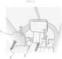
- Helicopters include a control input device including a cyclic control stick 1 for controlling a pitch and roll attitude, a tall rotor control pedal 2 for controlling a direction, and a collective control stick 3 for inputting an engine thrust and a collective pitch angle of the rotor blades.
- a fixed-wing aircraft is configured such that when both sides of the tall rotor control pedal 2 are stepped on at the same time, a brake function operates.
- US patent application 2009/187292 A1 discloses a method and apparatus for a control system for an aircraft.
- the control system comprises a grip, a set of feedback components connected to the grip, and a set of sensors.
- the set of feedback components transmit a restoring force opposite to a movement of the grip.
- the set of sensors are capable of detecting pitch input, roll input, and yaw input in response to the movement of the grip.
- US patent application 2017/217584 A1 discloses an air vehicle including a flight computer, a fuselage, and two rotors mounted symmetrically with respect to the fuselage. Each of the two rotors includes a servo mechanism to tilt a respective rotor of the two rotors about two axes of the respective rotor.
- the flight computer is configured to send control parameters to each of the two rotors, the control parameters including a rotational speed, a first tilt angle about a first axis of the two axes of the respective rotor, and a second tilt angle about a second axis of the two axes of the respective rotor.
- a method for operating the air vehicle is also provided.
- US patent application 2018/251210 A1 discloses a vehicular control system which can include a control device including one or more control inputs, and a control switch operatively connected to the control device for receiving control input signals from the control device, the control switch configured to switch between a vehicle control mode such that the control input signals control one or more vehicle motion control components and at least one mission mode such that the control input signals control one or more other devices.
- an automatic flight control system (autopilot) of a manned aircraft or a ground control system of an unmanned aircraft is provided with an automatic system that automatically maintains constant altitude, speed, heading, etc. to reduce the pilot's control burden, and is configured to input an input value through a knob input device.
- the knob input device of the manned aircraft may be located on a control instrument panel separate from the control stick input device and is provided to input a target altitude, speed and heading commands by turning a knob dial or applying a beep trim button of the control stick after pressing altitude (ALT), speed (IAS) and heading (HDG) buttons.
- altitude, speed, and heading commands may be input using a knob window and a dial input device of the ground control system (GCS).
- flight control may be performed by an ordinary person with a level of flight experience and control skills that are much less than those of a professional pilot. To this end, most of the flight control should be performed automatically, and manual control of an occupant is required only in emergencies, such as failure situations, but an autopilot allowing for a safe landing without a very high level of control skills should be provided.
- eVTOL electric-powered vertical take-off and landing
- An exemplary embodiment of the present invention is directed to providing a device capable of performing flight control using a single control device to simplify and facilitate a flight operation, compared with an existing control device, and easily inputting a control command through a control device, so as to be used in an electric vertical take-off and landing personal aircraft having an automatic flight control system.
- flight of an aircraft may be manipulated using one control device, so that even an unskilled pilot may more easily perform flight control, thereby improving work efficiency.
- a command value for automatic flight control to be input using the control device, the number of parts installed in the aircraft may be reduced, and the convenience of manipulation may be improved, thereby achieving an effect of improving the pilot convenience and stability of a flight operation through simple and accurate flight control.
- the above-described altitude command input method, speed command input method, heading command input method, and roll command input method can be performed with one and the same control input device.
- an aircraft control input device of the related art includes a cyclic control stick 1 for pitch and roll attitude control, a tall rotor control pedal 2 for direction control, and a collective control stick 3 for inputting a collective pitch angle of engine thrust and rotor blades, and the aircraft is configured to perform a corresponding mission by inputting a flight control command by using the plurality of control sticks in combination.
- the present invention relates to a control input device that commands an operation for flight control of an aircraft.
- the present invention is configured to input control commands necessary for flight control, such as a pitch attitude, roll attitude, direction control, engine thrust, blade pitch angle, wireless communication and a brake of an aircraft through one control stick. Therefore, even a pilot who is not proficient in controlling an aircraft may perform flight control more easily, and thus, because an ordinary person with a level of flight experience, control skills, and desired pay that is much more modest than those of a professional pilot may perform control, work efficiency may be improved and an effect of contributing to the popularization of vertical take-off and landing personal aircraft as a means of transportation in the future may be achieved.
- control input device of the present invention may be applied to an eVTOL aircraft, which is an electric powered vertical take-off and landing aircraft, and is intended to provide a device capable of performing flight control through the automatic control system and one control input device in an aircraft equipped with an automatic control system.
- the present invention relates to a control input device for inputting a control command for an operation of at least one of the pitch attitude, roll attitude, direction control, engine thrust, blade pitch angle, wireless communication, and brake of the aircraft for the control of a distributed propulsion electric-powered vertical take-off and landing aircraft having an automatic flight control device.
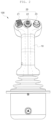
- the control input device 100 of the present invention may include a body portion 10 formed in the shape of a bar that may be gripped by hand to input the control command by an operation of pushing or pulling in every direction and a twisting operation in an axial direction and at least one position 21, 22, 23, and 24 formed in the body portion to input the control command by a manipulation operation.
- the aircraft of the present invention may include the control input device 100 for inputting an input value for an operation of the aircraft, a flight information monitor (FIM) 200 inputting commands by drawing or touching for a plurality of modules according to the flight information and automatic flight module of the aircraft, and a flight control computer controlling the aircraft according to input values.
- FIM flight information monitor
- the body portion 10 is formed so that a pilot may grip it with any one of a left hand or a right hand to use it, and is formed in a bar shape having a length in one direction so that the pilot may use the bar by holding it with his hand.
- the body portion 10 is connected to the aircraft on the other side and extends in one direction, so that one end of the body portion 10 may be gripped by the user.
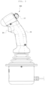
- the body portion 10 may be formed to be inclined at a certain angle on one side when extending in a length direction so that the pilot may grip the body portion 10 with his hand and easily use another device provided in the body portion 10 by using his fingers.
- the body portion 10 may have a form having an angle inclined toward the front from a central portion to one end in the length direction while the other end is vertically extended.
- the body portion 10 of the present invention may be movable in every direction and may be formed to allow a twisting operation in the axial direction of the body portion 10, and according to a movement or twisting operation of the body portion 10 in each direction, a certain control command may be input to a flight control computer, and the aircraft may perform an operation according to the command.
- a control command may be input to the body portion 10 through a pushing or pulling operation in a front-rear direction (Y-axis), and the control command at this time may be set as a control command for the pitch attitude of the aircraft.
- a control command may be input to the body portion 10 through a pushing or pulling operation in a left-right direction (X-axis), and the control command at this time may be set as a control command for the roll attitude of the aircraft.
- a control command may be input to the body portion 10 through a clockwise or counterclockwise twisting operation (Z axis) in the axial direction, and the control command at this time may be set as a control command for the direction control of the aircraft.
- the pilot may grip the body portion 10 with his hand and then push the body portion 10 to the right to input a command for the roll attitude of the aircraft, or may perform flight control by inputting a command so that the aircraft heads in the right direction by rotating the body portion 10 clockwise during stationary flight or low-speed flight.
- At least one position is formed on the body portion 10, and a control command is input to the aircraft by a manipulation operation of the position.
- the position may be provided in plurality according to the user's needs, and each position may be set to input a different command value.
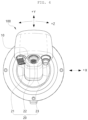
- the positions 21, 22, 23, and 24 are preferably arranged according to the shape of the body portion 10, and the positions 21, 22 and 23 may be located in a portion where each finger is located when the pilot grips the body portion 10 with his/her hand, or the position 24 may be located in a position that may be controlled using a finger, so that the pilot may easily and conveniently operate the position.
- the position may be used without limitation as long as it is a device capable of inputting input values to the flight control computer by any operation, and it is preferable to select and provide an appropriate operation according to the user's needs and purposes.
- the pilot may grip the bar portion of the body portion 10 such that all of the fingers excluding the thumb wraps the bar portion and the thumb contacts the other fingers.
- the first position 21, the second position 22, and the third position 23 may be formed in a portion in which the pilot's thumb is located in a state where the pilot grips the body portion 10, and the fourth position 24 may be formed at a position of one or more of the fingers other than the pilot's thumb.
- the control input device 100 of the present invention may have four positions 21, 22, 23, and 24, and among the four positions, three positions including the first, second, and third positions 21, 22, and 23 may be located at one end side of the body portion 10, and the remaining one position, which is the fourth position 24, may be located in a length portion of the body portion 10.
- the first, second, and third positions 21, 22, and 23 may be formed adjacent to each other at one end of the body portion 10, and may be arranged vertically in parallel to each other, but in an exemplary embodiment of the present invention, the first, second, and third positions 21, 22, and 23 are arranged side by side on the left and right of each other.
- the fourth position 24 may be formed at a position where the index or middle finger of the pilot's four fingers with smooth force control is located, and in an exemplary embodiment of the present invention, the fourth position 24 may be formed in a front direction of the body portion 10.
- the respective positions 21, 22, 23, and 24 may input different flight control commands according to operations.
- the flight control command at this time may include commands, such as engine thrust, wireless communication on/off, and brake.
- the first position 21 of the present invention may be formed in a form that may be operated in an up-down direction, and the first position 21 may be set to input a control command for the engine thrust of the aircraft when manipulated in the up-down direction.
- the first position 21 may be located on the leftmost side of one end of the body portion 10.
- the first position 21 may be manipulated upward using the pilot's thumb to input a higher value of thrust so that the aircraft may fly with a higher value of thrust.
- the second position 22 may be formed in the form of a joystick capable of moving the bar up, down, left, and right, and the second position 22 may be set to input a control command set by the user by moving the bar of the second position 22. At this time, the second position 22 may be located adjacent to the right side of the second position 22.
- the second position 22 may be formed to input a flight control command as needed, but as an exemplary embodiment of the present invention, the second position 22 is set to be used to input a command value for setting in a flight mode to be described later.
- the third position 23 of the present invention may be formed in the form of a button to be pressed, and may be set to input a control command to turn on or off wireless communication by pressing the third position 23.
- the third position 23 may be a button type in which a button is inserted when pressed once and protrudes to an existing height when the inserted button is pressed again. Accordingly, when the third position 23 protruding with the existing height is pressed once using the pilot's thumb, the wireless communication of the aircraft is commanded to be ON and an operation to be connected to perform wireless communication with the outside may be performed. Alternatively, it may be set to be ON only when the third position 23 is pressed, and OFF when not pressed.
- the aircraft of the present invention is a distributed electric-powered vertical take-off and landing (eVTOL) aircraft, it adopts a wing such as a fixed wing for a long flight, and should be able to slide and land in a fixed wing mode in an emergency, such as when a motor fails.
- a brake is required to stop after sliding on the ground. Therefore, the fourth position 24 of the present invention is formed on the front portion of the body portion 10, and may be formed at a position where at least one finger of the pilot's index and middle fingers is located, and is formed in a button type to be pressed, so that the aircraft may be set to input a brake control command through an operation of pressing the fourth position 24.
- the fourth position 24 may be formed to be perceived by distinguishing sensitivity of pressing the button type, and may be formed such that the degree of brake use of the aircraft is adjusted according to the pressure with which the pilot presses the fourth position 24.
- the fourth position 24 may be pressed hard with a pressure higher than a certain level, and when an input value received by the flight control computer from the fourth position 24 is identified as a pressure equal to or higher than a certain level, the brake may be operated at a certain level or higher to perform the emergency braking operation of the aircraft.
- it may be programmed in a computer so that a force of the break command is accumulated according to ON or OFF of the switch at the fourth position 24.
- a command value necessary for each mode may be input through the control input device 100.
- a method of inputting different command values by manipulating the position of the control input device 100 according to each mode will be described in more detail.
- the aircraft of the present invention may include a monitor 200 displaying flight information on a screen so that a pilot may check various information inside the aircraft.
- the monitor 200 may check flight information, but may be a touch screen capable of switching a controller to perform a selected mission or mode by touching the screen.
- the monitor 200 may have a plurality of modes formed as buttons on the monitor 200 for automatic flight control, and by touching a button of any mode according to the pilot's need, the flight control computer of the aircraft may be formed to be switched to perform the operation of the corresponding button.
- the aircraft may include an altitude speed maintenance mode 31 that maintains a constant altitude speed desired by the pilot.
- the altitude speed maintenance mode 31 may be displayed on the monitor 200 and may be activated by a pilot's touch.
- a screen for inputting an altitude speed maintenance command including at least one or more of altitude and speed may be executed.
- the present invention may use a position, and may be configured to input an altitude command value by manipulating the first position 21.
- the first position 21 of the present invention may be formed to input a command value in a first range by manipulating up and down, and in the altitude input, a high altitude may be input as a command value by manipulating the first position 21 upward. That is, when the pilot presses the altitude speed maintenance mode button 31 of the monitor 200 to activate the altitude speed maintenance mode, an altitude command value may be input by manipulating the first position 21 up or down, and according to the input command value, the aircraft may perform the altitude speed maintenance mode at a corresponding altitude.
- the present invention may use a position, and may be configured to input a speed command value by manipulating the second position 22.
- the second position 22 of the present invention may be in the form of a joystick capable of moving up and down, left and right, and may be configured to input a command value by moving the bar up and down.
- a high speed may be input as a command value by moving the second position 22 up. That is, when the altitude speed maintenance mode is activated by the pilot pressing the altitude speed maintenance mode button 31 of the monitor 200, the speed command value may be input by moving the second position 22 up or down, and according to the input command value, the aircraft may perform the altitude speed maintenance mode at the corresponding speed.
- a reference value that appears first on the monitor 200 may be an altitude and speed of the currently flying aircraft, and other values may be set according to the user's selection.
- the altitude speed maintenance mode may be released by the pilot by pressing the altitude speed maintenance mode button 31 of the monitor 200 once again, and according to the user's setting, the altitude speed maintenance mode may be set to be performed only for a certain period of time and released after a certain period of time.
- the altitude command value may be input by simultaneously manipulating the body portion 10 together with the first position 21, and the speed command value may be input by simultaneously manipulating the body portion 10 together with the second position 22.
- an altitude command value in a second range may be input by pushing or pulling the body portion 10 forward and backward while operating the first position 21 in the up-down direction.
- the command value in the second range that may be input by simultaneously manipulating the first position 21 and the body portion 10 may be greater than the command value in the first range that may be input by manipulating only the first position 21.
- a single click may increase an altitude command of 1 m, and when the first position 21 and the body portion 10 are simultaneously pushed or pulled in the front-rear direction, an altitude command by 10m may be increased.
- a speed command value in the second range may be input by pushing or pulling the body portion 10 in the front-rear direction, while operating the second position 22 in the up-down direction. At this time, the command value in the second range that may be input by simultaneously manipulating the second position 22 and the body portion 10 may be greater than the command value in the first range that may be input by manipulating only the second position 22.
- a speed command of 1 km/h may be increased with a single click, and a speed command of 10km/h may be increased by simultaneously pushing the second position 22 and the body portion 10 in the front-rear direction.
- the aircraft may include a heading maintenance mode 32 that constantly maintains a heading desired by the pilot.
- the heading maintenance mode 32 is displayed on the monitor 200 and may be activated by a pilot's touch.
- a screen for inputting a heading maintenance command may be executed.
- the present invention may use a position, and a heading command value in a first range may be input by manipulating the second position 22 in the left-right direction.
- the second position 22 of the present invention may be in the form of a joystick in which the bar may move up and down, and left and right, and a command value may be input by moving the bar in the left-right direction.
- a high heading value may be input as a command value by moving the second position 22 to the right. That is, when the pilot activates the heading maintenance mode by pressing the heading maintenance mode button 32 of the monitor 200, a heading command value may be input by moving the second position 22 to the left or right, and according to the received command value, the aircraft may perform the heading maintenance mode.
- a reference value that appears first on the monitor 200 for the heading value may be a heading value of the currently flying aircraft, and other values may be set according to the user's selection.
- the heading maintenance mode may be released by the pilot by pressing the header maintenance mode button 32 of the monitor 200 once again, and according to the user's setting, the heading maintenance mode may be set to be performed only for a certain period of time and may be released after the lapse of a certain period of time.
- a single click may increase a heading command or roll by 1 degree, and a heading command or roll command may be increased by 10 degrees when the second position 22 and the body portion 10 are simultaneously pulled to the right.
- the heading command or roll command may be increased by 10 degrees.
- the aircraft may include a roll maintenance mode 33 whereby the pilot constantly maintains a desired roll attitude.
- the roll maintenance mode 33 is displayed on the monitor 200 and may be activated by a pilot's touch.
- a screen for inputting a roll maintenance command may be executed.
- the present invention may use a position, and by manipulating the second position 22, a roll attitude command value in a first range may be input.
- the second position 22 of the present invention may be in the form of a joystick in which the bar may move up and down, left and right, and a command value may be input by moving the bar in the left-right direction.
- a high roll attitude value may be input as a command value by moving the second position 22 to the right. That is, when the pilot activates the roll maintenance mode by pressing the roll maintenance mode button 33 of the monitor 200, the roll attitude command value may be input by moving the second position 22 to the left or right, and according to the input command value, the aircraft may perform the roll maintenance mode.
- a reference value first displayed on the monitor 200 for the roll attitude command value may be a roll attitude value of the currently flying aircraft, and other values may be set according to the user's selection.
- the roll maintenance mode may be released by the pilot by pressing the roll maintenance mode button 33 of the monitor 200 once again, and the roll maintenance mode may be set to be performed only for a certain period of time and may be released after the certain period of time according to the user's setting.
- the roll maintenance mode button 32 when the heading maintenance mode button 32 is pressed while the roll maintenance mode is applied, the roll maintenance mode may be switched to the heading maintenance mode, and conversely, when the roll maintenance mode button 33 is pressed in a state in which the heading maintenance mode is applied, the heading maintenance mode may be switched to the roll maintenance mode.
- a roll command value may be input by simultaneously manipulating the body portion 10 together with the second position 22. More specifically, as a roll input method, a roll command value in the second range may be input by pushing or pulling the body portion 10 in the left-right direction, while operating the second position 21 in the left-right direction. At this time, the command value in the second range that may be input by simultaneously manipulating the second position 22 and the body portion 10 may be greater than the command value in the first range that may be input by manipulating only the second position 22.
- control input device 10 body portion 21: first position 22: second position 23: third position 24: fourth position 200: monitor 31: altitude speed maintenance mode button 32: heading maintenance mode button 33: roll maintenance mode button
Landscapes
- Engineering & Computer Science (AREA)
- Aviation & Aerospace Engineering (AREA)
- Automation & Control Theory (AREA)
- Mechanical Engineering (AREA)
- Mechanical Control Devices (AREA)
Description
- The following disclosure relates to a device for controlling an aircraft having an automatic flight control device, and a control input device for controlling an aircraft or inputting input values to be input to an automatic flight control using a single stick, and a command input method using the same.
- Referring to
FIG. 1 , a control input device of a helicopter, which is a general vertical take-off and landing aircraft, is described. Helicopters include a control input device including a cyclic control stick 1 for controlling a pitch and roll attitude, a tallrotor control pedal 2 for controlling a direction, and acollective control stick 3 for inputting an engine thrust and a collective pitch angle of the rotor blades. Meanwhile, a fixed-wing aircraft is configured such that when both sides of the tallrotor control pedal 2 are stepped on at the same time, a brake function operates. -
US patent application 2009/187292 A1 discloses a method and apparatus for a control system for an aircraft. The control system comprises a grip, a set of feedback components connected to the grip, and a set of sensors. The set of feedback components transmit a restoring force opposite to a movement of the grip. The set of sensors are capable of detecting pitch input, roll input, and yaw input in response to the movement of the grip.US patent application 2017/217584 A1 discloses an air vehicle including a flight computer, a fuselage, and two rotors mounted symmetrically with respect to the fuselage. Each of the two rotors includes a servo mechanism to tilt a respective rotor of the two rotors about two axes of the respective rotor. The flight computer is configured to send control parameters to each of the two rotors, the control parameters including a rotational speed, a first tilt angle about a first axis of the two axes of the respective rotor, and a second tilt angle about a second axis of the two axes of the respective rotor. A method for operating the air vehicle is also provided.US patent application 2018/251210 A1 discloses a vehicular control system which can include a control device including one or more control inputs, and a control switch operatively connected to the control device for receiving control input signals from the control device, the control switch configured to switch between a vehicle control mode such that the control input signals control one or more vehicle motion control components and at least one mission mode such that the control input signals control one or more other devices. - Because flight control using cyclic control sticks, pedals, and collective control sticks of these helicopters is mostly performed manually, pilots need a lot of training time and high-level control skills to learn helicopter flight control.
- In the related art case, an automatic flight control system (autopilot) of a manned aircraft or a ground control system of an unmanned aircraft is provided with an automatic system that automatically maintains constant altitude, speed, heading, etc. to reduce the pilot's control burden, and is configured to input an input value through a knob input device. In general, the knob input device of the manned aircraft may be located on a control instrument panel separate from the control stick input device and is provided to input a target altitude, speed and heading commands by turning a knob dial or applying a beep trim button of the control stick after pressing altitude (ALT), speed (IAS) and heading (HDG) buttons. In addition, in the case of an unmanned aerial vehicle, altitude, speed, and heading commands may be input using a knob window and a dial input device of the ground control system (GCS).
- In the case of an electric-powered vertical take-off and landing (eVTOL) personal aircraft, flight control may be performed by an ordinary person with a level of flight experience and control skills that are much less than those of a professional pilot. To this end, most of the flight control should be performed automatically, and manual control of an occupant is required only in emergencies, such as failure situations, but an autopilot allowing for a safe landing without a very high level of control skills should be provided.
- Accordingly, there is a need for a control input device allowing a pilot who is an ordinary person to easily operate the flight control.
- An exemplary embodiment of the present invention is directed to providing a device capable of performing flight control using a single control device to simplify and facilitate a flight operation, compared with an existing control device, and easily inputting a control command through a control device, so as to be used in an electric vertical take-off and landing personal aircraft having an automatic flight control system.
- This task is solved by the features of independent claims. Features of the dependent claims define embodiments.
- According to the aircraft control input device and the command input method using the same of the present invention according to the configuration as described above, unlike the related art in which flight control is performed using a plurality of control sticks in an existing aircraft, flight of an aircraft may be manipulated using one control device, so that even an unskilled pilot may more easily perform flight control, thereby improving work efficiency. In addition, by configuring a command value for automatic flight control to be input using the control device, the number of parts installed in the aircraft may be reduced, and the convenience of manipulation may be improved, thereby achieving an effect of improving the pilot convenience and stability of a flight operation through simple and accurate flight control. The above-described altitude command input method, speed command input method, heading command input method, and roll command input method can be performed with one and the same control input device.
-
-
FIG. 1 shows a conventional helicopter control stick. -
FIG. 2 is a front view of a control input device according to the present invention; -
FIG. 3 is a side view of a control input device according to the present invention; -
FIG. 4 shows a plane of a control input device according to the present invention; and -
FIG. 5 shows an example of a monitor according to the present invention. - Hereinafter, exemplary embodiments of the present invention will be described in detail with reference to the accompanying drawings. Prior to the description, it should be understood that the terms used in the specification and the appended claims should not be construed as limited to general and dictionary meanings, but interpreted based on the meanings and concepts corresponding to technical aspects of the present invention based on the principle that the inventor is allowed to define terms.
- Therefore, the description proposed herein is just a preferable example for the purpose of illustration only, and is not intended to limit the scope of protection, which is intended to be limited only by the appended claims.
- Hereinafter, the present invention will be described in more detail with reference to the accompanying drawings.
- Referring to
FIG. 1 , an aircraft control input device of the related art includes a cyclic control stick 1 for pitch and roll attitude control, a tallrotor control pedal 2 for direction control, and acollective control stick 3 for inputting a collective pitch angle of engine thrust and rotor blades, and the aircraft is configured to perform a corresponding mission by inputting a flight control command by using the plurality of control sticks in combination. - The present invention relates to a control input device that commands an operation for flight control of an aircraft. Unlike the related art, the present invention is configured to input control commands necessary for flight control, such as a pitch attitude, roll attitude, direction control, engine thrust, blade pitch angle, wireless communication and a brake of an aircraft through one control stick. Therefore, even a pilot who is not proficient in controlling an aircraft may perform flight control more easily, and thus, because an ordinary person with a level of flight experience, control skills, and desired pay that is much more modest than those of a professional pilot may perform control, work efficiency may be improved and an effect of contributing to the popularization of vertical take-off and landing personal aircraft as a means of transportation in the future may be achieved. In particular, the control input device of the present invention may be applied to an eVTOL aircraft, which is an electric powered vertical take-off and landing aircraft, and is intended to provide a device capable of performing flight control through the automatic control system and one control input device in an aircraft equipped with an automatic control system.
- The present invention relates to a control input device for inputting a control command for an operation of at least one of the pitch attitude, roll attitude, direction control, engine thrust, blade pitch angle, wireless communication, and brake of the aircraft for the control of a distributed propulsion electric-powered vertical take-off and landing aircraft having an automatic flight control device. Therefore, the
control input device 100 of the present invention may include abody portion 10 formed in the shape of a bar that may be gripped by hand to input the control command by an operation of pushing or pulling in every direction and a twisting operation in an axial direction and at least oneposition control input device 100 for inputting an input value for an operation of the aircraft, a flight information monitor (FIM) 200 inputting commands by drawing or touching for a plurality of modules according to the flight information and automatic flight module of the aircraft, and a flight control computer controlling the aircraft according to input values. - The
body portion 10 is formed so that a pilot may grip it with any one of a left hand or a right hand to use it, and is formed in a bar shape having a length in one direction so that the pilot may use the bar by holding it with his hand. Referring toFIGS. 1 to 3 , thebody portion 10 is connected to the aircraft on the other side and extends in one direction, so that one end of thebody portion 10 may be gripped by the user. Thebody portion 10 may be formed to be inclined at a certain angle on one side when extending in a length direction so that the pilot may grip thebody portion 10 with his hand and easily use another device provided in thebody portion 10 by using his fingers. In an exemplary embodiment of the present invention, thebody portion 10 may have a form having an angle inclined toward the front from a central portion to one end in the length direction while the other end is vertically extended. - Referring to
FIGS. 1 to 3 , thebody portion 10 of the present invention may be movable in every direction and may be formed to allow a twisting operation in the axial direction of thebody portion 10, and according to a movement or twisting operation of thebody portion 10 in each direction, a certain control command may be input to a flight control computer, and the aircraft may perform an operation according to the command. In an exemplary embodiment of the present invention, a control command may be input to thebody portion 10 through a pushing or pulling operation in a front-rear direction (Y-axis), and the control command at this time may be set as a control command for the pitch attitude of the aircraft. In addition, a control command may be input to thebody portion 10 through a pushing or pulling operation in a left-right direction (X-axis), and the control command at this time may be set as a control command for the roll attitude of the aircraft. In addition, a control command may be input to thebody portion 10 through a clockwise or counterclockwise twisting operation (Z axis) in the axial direction, and the control command at this time may be set as a control command for the direction control of the aircraft. For example, when the pilot wants to fly the aircraft to the right, the pilot may grip thebody portion 10 with his hand and then push thebody portion 10 to the right to input a command for the roll attitude of the aircraft, or may perform flight control by inputting a command so that the aircraft heads in the right direction by rotating thebody portion 10 clockwise during stationary flight or low-speed flight. - At least one position is formed on the
body portion 10, and a control command is input to the aircraft by a manipulation operation of the position. The position may be provided in plurality according to the user's needs, and each position may be set to input a different command value. Thepositions body portion 10, and thepositions body portion 10 with his/her hand, or theposition 24 may be located in a position that may be controlled using a finger, so that the pilot may easily and conveniently operate the position. The position may be used without limitation as long as it is a device capable of inputting input values to the flight control computer by any operation, and it is preferable to select and provide an appropriate operation according to the user's needs and purposes. - Referring to
FIGS. 1 to 3 , in an exemplary embodiment of the present invention, in thecontrol input device 100, the pilot may grip the bar portion of thebody portion 10 such that all of the fingers excluding the thumb wraps the bar portion and the thumb contacts the other fingers. At this time, thefirst position 21, thesecond position 22, and thethird position 23 may be formed in a portion in which the pilot's thumb is located in a state where the pilot grips thebody portion 10, and thefourth position 24 may be formed at a position of one or more of the fingers other than the pilot's thumb. More specifically, thecontrol input device 100 of the present invention may have fourpositions third positions body portion 10, and the remaining one position, which is thefourth position 24, may be located in a length portion of thebody portion 10. The first, second, andthird positions body portion 10, and may be arranged vertically in parallel to each other, but in an exemplary embodiment of the present invention, the first, second, andthird positions fourth position 24 may be formed at a position where the index or middle finger of the pilot's four fingers with smooth force control is located, and in an exemplary embodiment of the present invention, thefourth position 24 may be formed in a front direction of thebody portion 10. - The
respective positions - More specifically, the
first position 21 of the present invention may be formed in a form that may be operated in an up-down direction, and thefirst position 21 may be set to input a control command for the engine thrust of the aircraft when manipulated in the up-down direction. At this time, thefirst position 21 may be located on the leftmost side of one end of thebody portion 10. For example, when the pilot wants to increase thrust, thefirst position 21 may be manipulated upward using the pilot's thumb to input a higher value of thrust so that the aircraft may fly with a higher value of thrust. - The
second position 22 may be formed in the form of a joystick capable of moving the bar up, down, left, and right, and thesecond position 22 may be set to input a control command set by the user by moving the bar of thesecond position 22. At this time, thesecond position 22 may be located adjacent to the right side of thesecond position 22. Thesecond position 22 may be formed to input a flight control command as needed, but as an exemplary embodiment of the present invention, thesecond position 22 is set to be used to input a command value for setting in a flight mode to be described later. - In addition, the
third position 23 of the present invention may be formed in the form of a button to be pressed, and may be set to input a control command to turn on or off wireless communication by pressing thethird position 23. For example, thethird position 23 may be a button type in which a button is inserted when pressed once and protrudes to an existing height when the inserted button is pressed again. Accordingly, when thethird position 23 protruding with the existing height is pressed once using the pilot's thumb, the wireless communication of the aircraft is commanded to be ON and an operation to be connected to perform wireless communication with the outside may be performed. Alternatively, it may be set to be ON only when thethird position 23 is pressed, and OFF when not pressed. - If the aircraft of the present invention is a distributed electric-powered vertical take-off and landing (eVTOL) aircraft, it adopts a wing such as a fixed wing for a long flight, and should be able to slide and land in a fixed wing mode in an emergency, such as when a motor fails. At this time, a brake is required to stop after sliding on the ground. Therefore, the
fourth position 24 of the present invention is formed on the front portion of thebody portion 10, and may be formed at a position where at least one finger of the pilot's index and middle fingers is located, and is formed in a button type to be pressed, so that the aircraft may be set to input a brake control command through an operation of pressing thefourth position 24. At this time, thefourth position 24 may be formed to be perceived by distinguishing sensitivity of pressing the button type, and may be formed such that the degree of brake use of the aircraft is adjusted according to the pressure with which the pilot presses thefourth position 24. For example, when the pilot needs an emergency braking operation, thefourth position 24 may be pressed hard with a pressure higher than a certain level, and when an input value received by the flight control computer from thefourth position 24 is identified as a pressure equal to or higher than a certain level, the brake may be operated at a certain level or higher to perform the emergency braking operation of the aircraft. Alternatively, it may be programmed in a computer so that a force of the break command is accumulated according to ON or OFF of the switch at thefourth position 24. - In the present invention, when a plurality of automatic flight modes included in an automatic flight control device of the aircraft are executed using the
control input device 100 having the above characteristics, a command value necessary for each mode may be input through thecontrol input device 100. Hereinafter, a method of inputting different command values by manipulating the position of thecontrol input device 100 according to each mode will be described in more detail. - The aircraft of the present invention may include a
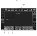
monitor 200 displaying flight information on a screen so that a pilot may check various information inside the aircraft. In this case, themonitor 200 may check flight information, but may be a touch screen capable of switching a controller to perform a selected mission or mode by touching the screen. Referring toFIG. 5 , themonitor 200 may have a plurality of modes formed as buttons on themonitor 200 for automatic flight control, and by touching a button of any mode according to the pilot's need, the flight control computer of the aircraft may be formed to be switched to perform the operation of the corresponding button. - In an exemplary embodiment of the present invention, the aircraft may include an altitude
speed maintenance mode 31 that maintains a constant altitude speed desired by the pilot. Referring toFIG. 5 , the altitudespeed maintenance mode 31 may be displayed on themonitor 200 and may be activated by a pilot's touch. When the pilot touches the altitudespeed maintenance mode 31, a screen for inputting an altitude speed maintenance command including at least one or more of altitude and speed may be executed. At this time, in order to input the altitude speed maintenance command, the present invention may use a position, and may be configured to input an altitude command value by manipulating thefirst position 21. Thefirst position 21 of the present invention may be formed to input a command value in a first range by manipulating up and down, and in the altitude input, a high altitude may be input as a command value by manipulating thefirst position 21 upward. That is, when the pilot presses the altitude speedmaintenance mode button 31 of themonitor 200 to activate the altitude speed maintenance mode, an altitude command value may be input by manipulating thefirst position 21 up or down, and according to the input command value, the aircraft may perform the altitude speed maintenance mode at a corresponding altitude. In addition, in order to input the altitude speed maintenance command, the present invention may use a position, and may be configured to input a speed command value by manipulating thesecond position 22. Thesecond position 22 of the present invention may be in the form of a joystick capable of moving up and down, left and right, and may be configured to input a command value by moving the bar up and down. For example, in a speed input, a high speed may be input as a command value by moving thesecond position 22 up. That is, when the altitude speed maintenance mode is activated by the pilot pressing the altitude speedmaintenance mode button 31 of themonitor 200, the speed command value may be input by moving thesecond position 22 up or down, and according to the input command value, the aircraft may perform the altitude speed maintenance mode at the corresponding speed. At this time, for the altitude and speed, a reference value that appears first on themonitor 200 may be an altitude and speed of the currently flying aircraft, and other values may be set according to the user's selection. The altitude speed maintenance mode may be released by the pilot by pressing the altitude speedmaintenance mode button 31 of themonitor 200 once again, and according to the user's setting, the altitude speed maintenance mode may be set to be performed only for a certain period of time and released after a certain period of time. - In addition, in the altitude
speed maintenance mode 31, the altitude command value may be input by simultaneously manipulating thebody portion 10 together with thefirst position 21, and the speed command value may be input by simultaneously manipulating thebody portion 10 together with thesecond position 22. More specifically, as an altitude input method, an altitude command value in a second range may be input by pushing or pulling thebody portion 10 forward and backward while operating thefirst position 21 in the up-down direction. At this time, the command value in the second range that may be input by simultaneously manipulating thefirst position 21 and thebody portion 10 may be greater than the command value in the first range that may be input by manipulating only thefirst position 21. - For example, when only the
first position 21 is pushed up, a single click may increase an altitude command of 1 m, and when thefirst position 21 and thebody portion 10 are simultaneously pushed or pulled in the front-rear direction, an altitude command by 10m may be increased. In addition, as a speed input method, a speed command value in the second range may be input by pushing or pulling thebody portion 10 in the front-rear direction, while operating thesecond position 22 in the up-down direction. At this time, the command value in the second range that may be input by simultaneously manipulating thesecond position 22 and thebody portion 10 may be greater than the command value in the first range that may be input by manipulating only thesecond position 22. For example, when only thesecond position 22 is pushed upward, a speed command of 1 km/h may be increased with a single click, and a speed command of 10km/h may be increased by simultaneously pushing thesecond position 22 and thebody portion 10 in the front-rear direction. - In an exemplary embodiment of the invention, the aircraft may include a heading
maintenance mode 32 that constantly maintains a heading desired by the pilot. Referring toFIG. 5 , the headingmaintenance mode 32 is displayed on themonitor 200 and may be activated by a pilot's touch. When the pilot touches the headingmaintenance mode 32, a screen for inputting a heading maintenance command may be executed. At this time, in order to input the heading maintenance command, the present invention may use a position, and a heading command value in a first range may be input by manipulating thesecond position 22 in the left-right direction. Thesecond position 22 of the present invention may be in the form of a joystick in which the bar may move up and down, and left and right, and a command value may be input by moving the bar in the left-right direction. For example, in inputting a heading command value, a high heading value may be input as a command value by moving thesecond position 22 to the right. That is, when the pilot activates the heading maintenance mode by pressing the headingmaintenance mode button 32 of themonitor 200, a heading command value may be input by moving thesecond position 22 to the left or right, and according to the received command value, the aircraft may perform the heading maintenance mode. In this case, a reference value that appears first on themonitor 200 for the heading value may be a heading value of the currently flying aircraft, and other values may be set according to the user's selection. The heading maintenance mode may be released by the pilot by pressing the headermaintenance mode button 32 of themonitor 200 once again, and according to the user's setting, the heading maintenance mode may be set to be performed only for a certain period of time and may be released after the lapse of a certain period of time. - In addition, in the heading
maintenance mode 32, a heading command value may be input by simultaneously manipulating thebody portion 10 together with thesecond position 22. More specifically, as a heading input method, a heading command value in the second range may be input by pushing or pulling thebody portion 10 in the left-right direction, while operating thesecond position 21 in the left-right direction. Alternatively, as a heading input method, a heading command value in the second range may be input by twisting and rotating thebody portion 10 in the left-right direction, while manipulating thesecond position 21 in the left-right direction. At this time, the command value in the second range that may be input by simultaneously manipulating thesecond position 22 and thebody portion 10 may be greater than the command value in the first range that may be input by manipulating only thesecond position 22. - For example, when only the
second position 22 is pushed to the right, a single click may increase a heading command or roll by 1 degree, and a heading command or roll command may be increased by 10 degrees when thesecond position 22 and thebody portion 10 are simultaneously pulled to the right. Alternatively, when thesecond position 22 and thebody portion 10 are twisted to the right at the same time, the heading command or roll command may be increased by 10 degrees. - In an exemplary embodiment of the present invention, the aircraft may include a
roll maintenance mode 33 whereby the pilot constantly maintains a desired roll attitude. Referring toFIG. 5 , theroll maintenance mode 33 is displayed on themonitor 200 and may be activated by a pilot's touch. When the pilot touches theroll maintenance mode 33, a screen for inputting a roll maintenance command may be executed. At this time, in order to input the roll maintenance command, the present invention may use a position, and by manipulating thesecond position 22, a roll attitude command value in a first range may be input. Thesecond position 22 of the present invention may be in the form of a joystick in which the bar may move up and down, left and right, and a command value may be input by moving the bar in the left-right direction. For example, in the roll attitude command value input, a high roll attitude value may be input as a command value by moving thesecond position 22 to the right. That is, when the pilot activates the roll maintenance mode by pressing the rollmaintenance mode button 33 of themonitor 200, the roll attitude command value may be input by moving thesecond position 22 to the left or right, and according to the input command value, the aircraft may perform the roll maintenance mode. At this time, a reference value first displayed on themonitor 200 for the roll attitude command value may be a roll attitude value of the currently flying aircraft, and other values may be set according to the user's selection. The roll maintenance mode may be released by the pilot by pressing the rollmaintenance mode button 33 of themonitor 200 once again, and the roll maintenance mode may be set to be performed only for a certain period of time and may be released after the certain period of time according to the user's setting. In addition, when the headingmaintenance mode button 32 is pressed while the roll maintenance mode is applied, the roll maintenance mode may be switched to the heading maintenance mode, and conversely, when the rollmaintenance mode button 33 is pressed in a state in which the heading maintenance mode is applied, the heading maintenance mode may be switched to the roll maintenance mode. - In addition, in the
roll maintenance mode 32, a roll command value may be input by simultaneously manipulating thebody portion 10 together with thesecond position 22. More specifically, as a roll input method, a roll command value in the second range may be input by pushing or pulling thebody portion 10 in the left-right direction, while operating thesecond position 21 in the left-right direction. At this time, the command value in the second range that may be input by simultaneously manipulating thesecond position 22 and thebody portion 10 may be greater than the command value in the first range that may be input by manipulating only thesecond position 22. - Hereinabove, although the present invention has been described by specific matters, such as detailed components, exemplary embodiments, and the accompanying drawings, they have been provided only for assisting in the entire understanding of the present invention. Therefore, the present invention is not limited to the exemplary embodiments. Various modifications and changes, which remain within the scope of the appended claims, may be made by those skilled in the art to which the present invention pertains from this description.
-
100: control input device 10: body portion 21: first position 22: second position 23: third position 24: fourth position 200: monitor 31: altitude speed maintenance mode button 32: heading maintenance mode button 33: roll maintenance mode button
Claims (8)
- A command input method for inputting an altitude speed maintenance command using a control input device (100) comprising: a body portion (10) formed in a bar shape grippable by hand and configured for inputting the control command through an operation of pushing or pulling in every direction and a twisting operation in an axial direction; and at least one position (21, 22, 23, 24) formed in the body portion (10) to input the control command by a manipulation operation, whereinan altitude speed maintenance mode of the aircraft is performed by selecting an altitude speed maintaining module from a monitor (200) showing flight information of the aircraft and inputting at least any one of an altitude command value and a speed command value by operating the at least one position (21, 22, 23, 24) of the control input device (100),the monitor includes a plurality of modules for automatic flight control to be a touch screen switched into a selected module when the touch screen is touched for the selected module,the at least one position includes a first position (21) formed in a portion in which the thumb is located in a state in which the body portion (10) of the control input device (100) is gripped, and operating while moving in an up-down direction,an altitude command value in a first range is input by manipulating the first position (21) in the altitude speed maintenance mode,an altitude command value in a second range is input by pushing or pulling the body portion (10) in a front-rear direction, while manipulating the first position (21) in the up-down direction, andthe second range is a value greater than the first range.
- A command input method for inputting an altitude speed maintenance command using a control input device (100) comprising: a body portion (10) formed in a bar shape grippable by hand and configured for inputting the control command through an operation of pushing or pulling in every direction and a twisting operation in an axial direction; and at least one position (21, 22, 23, 24) formed in the body portion (10) to input the control command by a manipulation operation, wherein,an altitude speed maintenance mode of the aircraft is performed by selecting an altitude speed maintaining module from a monitor (200) showing flight information of the aircraft and inputting at least any one of an altitude command value and a speed command value by operating the at least one position (21, 22, 23, 24) of the control input device (100),the monitor includes a plurality of modules for automatic flight control to be a touch screen switched into a selected module when the touch screen is touched for the selected module,the at least one position includes a second position (22) formed in a portion in which the thumb is located in a state in which the body portion (10) is gripped, and operating, while moving a bar up and down and left and right,a speed command value in the first range is input by manipulating the second position (22) in the up-down direction,a speed command value in a second range is input by manipulating the second position (22) in the up-down direction and simultaneously pushing or pulling the body portion (10) in a forward-backward direction, andthe second range is a value greater than the first range.
- A command input method for inputting a heading maintenance command using a control input device (100) comprising: a body portion (10) formed in a bar shape grippable by hand and configured for inputting the control command through an operation of pushing or pulling in every direction and a twisting operation in an axial direction; and at least one position (21, 22, 23, 24) formed in the body portion (10) to input the control command by a manipulation operation, whereina heading maintenance mode of the aircraft is performed by selecting a heading maintenance mode from a monitor (200) showing flight information of the aircraft and inputting a heading command value by manipulating the at least one position (21, 22, 23, 24) of the control input device (100),the monitor (200) includes a plurality of modules for automatic flight control to be a touch screen switched into a selected module when the touch screen is touched for the selected module,the at least one position of the control input device (100) includes a second position (22) formed in a portion in which the thumb is located in a state in which the body portion (10) is gripped, and operating, while moving a bar up and down and left and right,a heading command value in a first range is input by manipulating the second position (22) in the left-right direction,a heading command value in a second range is input by manipulating the second position (22) in a left-right direction and simultaneously pushing or pulling the body portion (100) in the left-right direction, or the heading command value in the second range is input by twisting the body portion (100) to the left and right and simultaneously manipulating the second position (22) in the left-right direction, andthe second range is a value greater than the first range.
- A command input method for inputting a roll maintenance command using a control input device (100) comprising: a body portion (10) formed in a bar shape grippable by hand and configured for inputting the control command through an operation of pushing or pulling in every direction and a twisting operation in an axial direction; and at least one position (21, 22, 23, 24) formed in the body portion (10) to input the control command by a manipulation operation, whereina roll maintenance mode of the aircraft is performed by selecting a roll maintenance mode from a monitor (200) showing flight information of the aircraft and inputting a roll command value by manipulating the at least one position (21, 22, 23, 24) of the control input device (100),the monitor (200) includes a plurality of modules for automatic flight control to be a touch screen switched into a selected module when the touch screen is touched for the selected module,the at least one position includes a second position (22) formed in a portion in which the thumb is located in a state in which the body portion (10) is gripped, and operating, while moving a bar up and down and left and right,a roll command value in a first range is input by manipulating the second position (22) in a left-right direction,a roll command value in a second range is input by manipulating the second position (22) in the left-right direction and simultaneously pushing or pulling the body portion (10) in the left-right direction, andthe second range is a value greater than the first range.
- A control input device (100) for inputting a control command for at least one operation of pitch attitude, roll attitude, direction control, engine thrust, blade pitch angle, wireless communication, and brake of aircraft to control the aircraft, the control input device (100) comprising:a body portion (10) formed in a bar shape grippable by hand and inputting the control command through an operation of pushing or pulling in every direction and a twisting operation in an axial direction; andat least one position (21, 22, 23, 24) formed in the body portion (10) to input the control command by a manipulation operation,characterised in that the control input device is configured to carry out the method according to any one of claims 1 to 4.
- The control input device (100) of claim 5, whereinthe body portion (10) inputs a control command for the pitch attitude of the aircraft through the operation of pushing or pulling in front-rear direction,inputs a control command for the roll attitude of the aircraft through the operation of pushing or pulling in left-right direction, andinputs a control command for direction control of the aircraft through a clockwise or counterclockwise twisting operation in an axial direction.
- The control input device (100) of claim 5 or claim 6, wherein
the at least one position comprises:a first position (21), a second position (22), and a third position (23) formed in a portion in which a thumb is located in a state in which the body portion is gripped; anda fourth position (24) formed in a portion in which any one of the remaining fingers excluding the thumb is located in a state in which the body portion is gripped. - The control input device (100) of claim 7, whereinthe first position (21) operates while moving in an up-down direction anda control command for a magnitude of an engine thrust of the aircraft is input through an operation of moving the first position (21) in the up-down direction,the third position (23) is formed in the form of a button to be pressed,a control command for turning on/off wireless voice communication of the aircraft is input through an operation of pressing the third position (23),the fourth position (24) is formed in the form of a button to be pressed, anda brake control command of the aircraft is input through an operation of pressing the fourth position (24).
Applications Claiming Priority (2)
| Application Number | Priority Date | Filing Date | Title |
|---|---|---|---|
| KR20210170628 | 2021-12-02 | ||
| KR1020220119588A KR102778097B1 (en) | 2021-12-02 | 2022-09-21 | Aircraft control input device and command input method using the same |
Publications (3)
| Publication Number | Publication Date |
|---|---|
| EP4190690A1 EP4190690A1 (en) | 2023-06-07 |
| EP4190690C0 EP4190690C0 (en) | 2025-03-19 |
| EP4190690B1 true EP4190690B1 (en) | 2025-03-19 |
Family
ID=84387746
Family Applications (1)
| Application Number | Title | Priority Date | Filing Date |
|---|---|---|---|
| EP22211029.8A Active EP4190690B1 (en) | 2021-12-02 | 2022-12-02 | Aircraft control input device and command input method using the same |
Country Status (2)
| Country | Link |
|---|---|
| US (1) | US12473075B2 (en) |
| EP (1) | EP4190690B1 (en) |
Families Citing this family (1)
| Publication number | Priority date | Publication date | Assignee | Title |
|---|---|---|---|---|
| EP4631858A1 (en) * | 2024-04-08 | 2025-10-15 | Ratier-Figeac SAS | Flight control system |
Family Cites Families (20)
| Publication number | Priority date | Publication date | Assignee | Title |
|---|---|---|---|---|
| US4584510A (en) * | 1982-09-08 | 1986-04-22 | The United States Of America As Represented By The Administrator Of The National Aeronautics And Space Administration | Thumb-actuated two-axis controller |
| FR2903659B1 (en) * | 2006-07-12 | 2008-09-26 | Airbus France Sas | FLIGHT CONTROL AND BRAKE SYSTEM FOR AN AIRCRAFT. |
| US20090187292A1 (en) | 2008-01-17 | 2009-07-23 | Mark Andrew Hreha | Integrated pitch, roll, and yaw inceptor |
| CN103562064A (en) * | 2011-05-12 | 2014-02-05 | 庞巴迪公司 | Controller |
| RU2623792C2 (en) * | 2012-02-10 | 2017-06-29 | Мерлин Технолоджи, Инк. | Autopilot system and method |
| CN105938369B (en) * | 2013-06-25 | 2018-11-02 | 深圳市大疆创新科技有限公司 | Aircraft control system and control method |
| JP2015112929A (en) * | 2013-12-10 | 2015-06-22 | 須知 晃一 | Manufacturing method and components of flying body for individual's aerial work |
| US9415862B2 (en) * | 2013-12-18 | 2016-08-16 | Merlin Technology, Inc. | Control interface, system and method |
| FR3024126B1 (en) * | 2014-07-25 | 2019-05-17 | Airbus Operations (S.A.S.) | CONTROL SYSTEM OF AN AIRCRAFT |
| US10150561B2 (en) * | 2016-02-01 | 2018-12-11 | King Fahd University Of Petroleum And Minerals | System and method of operation of twin-tiltrotor helicopter |
| GB2549271B (en) * | 2016-04-11 | 2021-07-14 | Bae Systems Plc | An aircraft |
| US10114382B2 (en) * | 2016-05-10 | 2018-10-30 | Sikorsky Aircraft Corporation | Flexible command model for aircraft control |
| EP3532842A4 (en) * | 2016-10-27 | 2020-12-16 | Fluidity Technologies, Inc. | Dynamically balanced multi-degrees-of-freedom hand controller |
| US20180251210A1 (en) * | 2017-03-03 | 2018-09-06 | Sikorsky Aircraft Corporation, A Lockheed Martin Company | Vehicle control systems |
| FR3074330A1 (en) * | 2017-11-28 | 2019-05-31 | Airbus Helicopters | METHOD FOR CONTROLLING AN AUTOMATIC AIRCRAFT DRIVER, ASSOCIATED CONTROL SYSTEM AND AIRCRAFT EQUIPPED WITH SUCH A CONTROL SYSTEM |
| KR102010424B1 (en) * | 2017-12-21 | 2019-08-14 | 한국항공우주연구원 | A method and computer program for controlling the tilt angle of the main rotor based on the pitch attitude control signal in the low speed region |
| EP3891067B1 (en) * | 2018-12-07 | 2024-01-17 | Joby Aero, Inc. | Aircraft control system and method |
| EP3670334B1 (en) | 2018-12-21 | 2021-03-10 | LEONARDO S.p.A. | Hand-operable man-machine interface for aircraft, drone remote control systems, flight simulators, spacecraft and the like |
| US11673649B2 (en) * | 2020-06-05 | 2023-06-13 | Joby Aero, Inc. | Aircraft control system and method |
| KR102778097B1 (en) * | 2021-12-02 | 2025-03-11 | 한국항공우주연구원 | Aircraft control input device and command input method using the same |
-
2022
- 2022-12-02 US US18/061,042 patent/US12473075B2/en active Active
- 2022-12-02 EP EP22211029.8A patent/EP4190690B1/en active Active
Also Published As
| Publication number | Publication date |
|---|---|
| EP4190690C0 (en) | 2025-03-19 |
| US20230286645A1 (en) | 2023-09-14 |
| EP4190690A1 (en) | 2023-06-07 |
| US12473075B2 (en) | 2025-11-18 |
Similar Documents
| Publication | Publication Date | Title |
|---|---|---|
| KR102778097B1 (en) | Aircraft control input device and command input method using the same | |
| US9033284B2 (en) | Integrated seat mounted inceptor | |
| CN116529159B (en) | System and method for a VTOL aircraft flight control manipulator | |
| CA2718080C (en) | Rotational aircraft throttle interface | |
| US11377200B2 (en) | Apparatus and method for piloting an aircraft | |
| EP3998198A1 (en) | Aircraft inceptor apparatus and aircraft flight control system | |
| EP3442862A1 (en) | An aircraft | |
| US10737775B2 (en) | Control member, a rotary wing aircraft, and a method | |
| US11820491B2 (en) | Aircraft control system and associated aircraft | |
| EP4190690A1 (en) | Aircraft control input device and command input method using the same | |
| US12351332B2 (en) | Aircraft flight control | |
| KR101506805B1 (en) | Using the touch panel rotorcraft autopilot and automatic control method | |
| US20260048835A1 (en) | Systems, methods, and devices for an aircraft control system | |
| CN219506218U (en) | Aircraft handling assembly | |
| US20250368317A1 (en) | Systems, methods, and devices for operation of a vehicle | |
| CN115520371B (en) | A control method, system, aircraft, and medium for an aircraft. | |
| EP4631852A1 (en) | Flight control system | |
| CN223420919U (en) | Control equipment, cockpits and vertical take-off and landing vehicles | |
| WO2025188759A1 (en) | Systems, methods, and devices for an aircraft control system | |
| CN223702934U (en) | Control equipment and vertical takeoff and landing aircraft | |
| CN219565448U (en) | Aircraft handling assembly | |
| EP4631858A1 (en) | Flight control system | |
| CN119429127A (en) | A control system for a vertical take-off and landing aircraft with a composite wing configuration and the aircraft | |
| CN121070005A (en) | Composite wing aircraft and control system thereof |
Legal Events
| Date | Code | Title | Description |
|---|---|---|---|
| PUAI | Public reference made under article 153(3) epc to a published international application that has entered the european phase |
Free format text: ORIGINAL CODE: 0009012 |
|
| STAA | Information on the status of an ep patent application or granted ep patent |
Free format text: STATUS: THE APPLICATION HAS BEEN PUBLISHED |
|
| AK | Designated contracting states |
Kind code of ref document: A1 Designated state(s): AL AT BE BG CH CY CZ DE DK EE ES FI FR GB GR HR HU IE IS IT LI LT LU LV MC ME MK MT NL NO PL PT RO RS SE SI SK SM TR |
|
| STAA | Information on the status of an ep patent application or granted ep patent |
Free format text: STATUS: REQUEST FOR EXAMINATION WAS MADE |
|
| 17P | Request for examination filed |
Effective date: 20231205 |
|
| RBV | Designated contracting states (corrected) |
Designated state(s): AL AT BE BG CH CY CZ DE DK EE ES FI FR GB GR HR HU IE IS IT LI LT LU LV MC ME MK MT NL NO PL PT RO RS SE SI SK SM TR |
|
| GRAP | Despatch of communication of intention to grant a patent |
Free format text: ORIGINAL CODE: EPIDOSNIGR1 |
|
| STAA | Information on the status of an ep patent application or granted ep patent |
Free format text: STATUS: GRANT OF PATENT IS INTENDED |
|
| INTG | Intention to grant announced |
Effective date: 20241014 |
|
| GRAS | Grant fee paid |
Free format text: ORIGINAL CODE: EPIDOSNIGR3 |
|
| GRAA | (expected) grant |
Free format text: ORIGINAL CODE: 0009210 |
|
| STAA | Information on the status of an ep patent application or granted ep patent |
Free format text: STATUS: THE PATENT HAS BEEN GRANTED |
|
| AK | Designated contracting states |
Kind code of ref document: B1 Designated state(s): AL AT BE BG CH CY CZ DE DK EE ES FI FR GB GR HR HU IE IS IT LI LT LU LV MC ME MK MT NL NO PL PT RO RS SE SI SK SM TR |
|
| REG | Reference to a national code |
Ref country code: GB Ref legal event code: FG4D |
|
| REG | Reference to a national code |
Ref country code: CH Ref legal event code: EP |
|
| REG | Reference to a national code |
Ref country code: DE Ref legal event code: R096 Ref document number: 602022011937 Country of ref document: DE |
|
| REG | Reference to a national code |
Ref country code: IE Ref legal event code: FG4D |
|
| U01 | Request for unitary effect filed |
Effective date: 20250416 |
|
| U07 | Unitary effect registered |
Designated state(s): AT BE BG DE DK EE FI FR IT LT LU LV MT NL PT RO SE SI Effective date: 20250424 |
|
| PG25 | Lapsed in a contracting state [announced via postgrant information from national office to epo] |
Ref country code: RS Free format text: LAPSE BECAUSE OF FAILURE TO SUBMIT A TRANSLATION OF THE DESCRIPTION OR TO PAY THE FEE WITHIN THE PRESCRIBED TIME-LIMIT Effective date: 20250619 |
|
| PG25 | Lapsed in a contracting state [announced via postgrant information from national office to epo] |
Ref country code: NO Free format text: LAPSE BECAUSE OF FAILURE TO SUBMIT A TRANSLATION OF THE DESCRIPTION OR TO PAY THE FEE WITHIN THE PRESCRIBED TIME-LIMIT Effective date: 20250619 |
|
| PG25 | Lapsed in a contracting state [announced via postgrant information from national office to epo] |
Ref country code: HR Free format text: LAPSE BECAUSE OF FAILURE TO SUBMIT A TRANSLATION OF THE DESCRIPTION OR TO PAY THE FEE WITHIN THE PRESCRIBED TIME-LIMIT Effective date: 20250319 |
|
| PG25 | Lapsed in a contracting state [announced via postgrant information from national office to epo] |
Ref country code: GR Free format text: LAPSE BECAUSE OF FAILURE TO SUBMIT A TRANSLATION OF THE DESCRIPTION OR TO PAY THE FEE WITHIN THE PRESCRIBED TIME-LIMIT Effective date: 20250620 |
|
| PG25 | Lapsed in a contracting state [announced via postgrant information from national office to epo] |
Ref country code: SM Free format text: LAPSE BECAUSE OF FAILURE TO SUBMIT A TRANSLATION OF THE DESCRIPTION OR TO PAY THE FEE WITHIN THE PRESCRIBED TIME-LIMIT Effective date: 20250319 |
|
| PG25 | Lapsed in a contracting state [announced via postgrant information from national office to epo] |
Ref country code: ES Free format text: LAPSE BECAUSE OF FAILURE TO SUBMIT A TRANSLATION OF THE DESCRIPTION OR TO PAY THE FEE WITHIN THE PRESCRIBED TIME-LIMIT Effective date: 20250319 |
|
| PG25 | Lapsed in a contracting state [announced via postgrant information from national office to epo] |
Ref country code: PL Free format text: LAPSE BECAUSE OF FAILURE TO SUBMIT A TRANSLATION OF THE DESCRIPTION OR TO PAY THE FEE WITHIN THE PRESCRIBED TIME-LIMIT Effective date: 20250319 |
|
| PG25 | Lapsed in a contracting state [announced via postgrant information from national office to epo] |
Ref country code: CZ Free format text: LAPSE BECAUSE OF FAILURE TO SUBMIT A TRANSLATION OF THE DESCRIPTION OR TO PAY THE FEE WITHIN THE PRESCRIBED TIME-LIMIT Effective date: 20250319 |
|
| PG25 | Lapsed in a contracting state [announced via postgrant information from national office to epo] |
Ref country code: SK Free format text: LAPSE BECAUSE OF FAILURE TO SUBMIT A TRANSLATION OF THE DESCRIPTION OR TO PAY THE FEE WITHIN THE PRESCRIBED TIME-LIMIT Effective date: 20250319 |
|
| PG25 | Lapsed in a contracting state [announced via postgrant information from national office to epo] |
Ref country code: IS Free format text: LAPSE BECAUSE OF FAILURE TO SUBMIT A TRANSLATION OF THE DESCRIPTION OR TO PAY THE FEE WITHIN THE PRESCRIBED TIME-LIMIT Effective date: 20250719 |
|
| PLBE | No opposition filed within time limit |
Free format text: ORIGINAL CODE: 0009261 |
|
| STAA | Information on the status of an ep patent application or granted ep patent |
Free format text: STATUS: NO OPPOSITION FILED WITHIN TIME LIMIT |
|
| REG | Reference to a national code |
Ref country code: CH Ref legal event code: L10 Free format text: ST27 STATUS EVENT CODE: U-0-0-L10-L00 (AS PROVIDED BY THE NATIONAL OFFICE) Effective date: 20260128 |
|
| U20 | Renewal fee for the european patent with unitary effect paid |
Year of fee payment: 4 Effective date: 20251223 |
|
| 26N | No opposition filed |
Effective date: 20251222 |