EP4190680A1 - Power-measuring devices - Google Patents
Power-measuring devices Download PDFInfo
- Publication number
- EP4190680A1 EP4190680A1 EP22210624.7A EP22210624A EP4190680A1 EP 4190680 A1 EP4190680 A1 EP 4190680A1 EP 22210624 A EP22210624 A EP 22210624A EP 4190680 A1 EP4190680 A1 EP 4190680A1
- Authority
- EP
- European Patent Office
- Prior art keywords
- spindle
- power
- section
- measuring device
- outer diameter
- Prior art date
- Legal status (The legal status is an assumption and is not a legal conclusion. Google has not performed a legal analysis and makes no representation as to the accuracy of the status listed.)
- Pending
Links
Images






Classifications
-
- B—PERFORMING OPERATIONS; TRANSPORTING
- B62—LAND VEHICLES FOR TRAVELLING OTHERWISE THAN ON RAILS
- B62M—RIDER PROPULSION OF WHEELED VEHICLES OR SLEDGES; POWERED PROPULSION OF SLEDGES OR SINGLE-TRACK CYCLES; TRANSMISSIONS SPECIALLY ADAPTED FOR SUCH VEHICLES
- B62M3/00—Construction of cranks operated by hand or foot
- B62M3/16—Accessories
-
- B—PERFORMING OPERATIONS; TRANSPORTING
- B62—LAND VEHICLES FOR TRAVELLING OTHERWISE THAN ON RAILS
- B62M—RIDER PROPULSION OF WHEELED VEHICLES OR SLEDGES; POWERED PROPULSION OF SLEDGES OR SINGLE-TRACK CYCLES; TRANSMISSIONS SPECIALLY ADAPTED FOR SUCH VEHICLES
- B62M3/00—Construction of cranks operated by hand or foot
- B62M3/08—Pedals
-
- B—PERFORMING OPERATIONS; TRANSPORTING
- B62—LAND VEHICLES FOR TRAVELLING OTHERWISE THAN ON RAILS
- B62J—CYCLE SADDLES OR SEATS; AUXILIARY DEVICES OR ACCESSORIES SPECIALLY ADAPTED TO CYCLES AND NOT OTHERWISE PROVIDED FOR, e.g. ARTICLE CARRIERS OR CYCLE PROTECTORS
- B62J45/00—Electrical equipment arrangements specially adapted for use as accessories on cycles, not otherwise provided for
- B62J45/40—Sensor arrangements; Mounting thereof
- B62J45/41—Sensor arrangements; Mounting thereof characterised by the type of sensor
- B62J45/411—Torque sensors
-
- B—PERFORMING OPERATIONS; TRANSPORTING
- B62—LAND VEHICLES FOR TRAVELLING OTHERWISE THAN ON RAILS
- B62J—CYCLE SADDLES OR SEATS; AUXILIARY DEVICES OR ACCESSORIES SPECIALLY ADAPTED TO CYCLES AND NOT OTHERWISE PROVIDED FOR, e.g. ARTICLE CARRIERS OR CYCLE PROTECTORS
- B62J45/00—Electrical equipment arrangements specially adapted for use as accessories on cycles, not otherwise provided for
- B62J45/40—Sensor arrangements; Mounting thereof
- B62J45/41—Sensor arrangements; Mounting thereof characterised by the type of sensor
-
- B—PERFORMING OPERATIONS; TRANSPORTING
- B62—LAND VEHICLES FOR TRAVELLING OTHERWISE THAN ON RAILS
- B62J—CYCLE SADDLES OR SEATS; AUXILIARY DEVICES OR ACCESSORIES SPECIALLY ADAPTED TO CYCLES AND NOT OTHERWISE PROVIDED FOR, e.g. ARTICLE CARRIERS OR CYCLE PROTECTORS
- B62J45/00—Electrical equipment arrangements specially adapted for use as accessories on cycles, not otherwise provided for
- B62J45/40—Sensor arrangements; Mounting thereof
- B62J45/42—Sensor arrangements; Mounting thereof characterised by mounting
- B62J45/421—Sensor arrangements; Mounting thereof characterised by mounting at the pedal crank
-
- B—PERFORMING OPERATIONS; TRANSPORTING
- B62—LAND VEHICLES FOR TRAVELLING OTHERWISE THAN ON RAILS
- B62M—RIDER PROPULSION OF WHEELED VEHICLES OR SLEDGES; POWERED PROPULSION OF SLEDGES OR SINGLE-TRACK CYCLES; TRANSMISSIONS SPECIALLY ADAPTED FOR SUCH VEHICLES
- B62M1/00—Rider propulsion of wheeled vehicles
- B62M1/36—Rider propulsion of wheeled vehicles with rotary cranks, e.g. with pedal cranks
-
- B—PERFORMING OPERATIONS; TRANSPORTING
- B60—VEHICLES IN GENERAL
- B60Y—INDEXING SCHEME RELATING TO ASPECTS CROSS-CUTTING VEHICLE TECHNOLOGY
- B60Y2200/00—Type of vehicle
- B60Y2200/10—Road Vehicles
- B60Y2200/13—Bicycles; Tricycles
Definitions
- This disclosure relates to bicycles and power-measuring devices for the bicycles.
- a bicycle power-measuring device also known as a power meter to some, is a device for measuring a rider's pedaling power during cycling.
- the pedaling power can be measured in the form of or converted or computed from the torque level a rider exerts in driving bike pedals and/or crank arms.
- a bicycle power-measuring device can be one or more strain gauges in one or both cranks or within one of both pedals.
- a deformation of a measuring device or gauge varies according to the amount of force applied. The change in strain characteristic or deformation of the strain gauge can then be measured, processed, and/or converted to derive the pedaling torque.
- a conventional bicycle power-measuring device needs various components that can take up a lot of space, which increases the overall size, weight, and/or placement of the power-measuring device. Furthermore, all the moving parts may be subject to water, physical impacts, dusts, mud, and/or weather conditions, which may impact the operability, accuracy, and reliability of the device.
- a power-measuring device which includes a spindle, a power gauge, an electrical circuit, and a cover.
- the spindle is configured to provide a coupling with a driving unit.
- the spindle includes a battery chamber within a hollow space of the spindle.
- the battery chamber is configured to receive a battery unit.
- the power gauge is coupled with the spindle to measure power applied to the spindle for driving a movement of the driving unit.
- the electrical circuit is electrically coupled with the power gauge.
- the electrical circuit is coupled with the battery and configured to receive and process signals from the power gauge.
- the cover is coupled with the spindle and arranged to enclose at least a portion of at least one of the power gauge and the electrical circuit.
- a bicycle includes crank arms configured to receive power from a rider, a driving unit configured to drive the bicycle through pedaling of the crank arms; and a power-measuring device.
- the power-measuring device includes a spindle, a power gauge, an electrical circuit, and a cover.
- the spindle is configured to provide a coupling with a driving unit.
- the spindle includes a battery chamber within a hollow space of the spindle.
- the battery chamber is configured to receive a battery unit.
- the power gauge is coupled with the spindle to measure power applied to the spindle for driving a movement of the driving unit.
- the electrical circuit is electrically coupled with the power gauge.
- the electrical circuit is coupled with the battery and configured to receive and process signals from the power gauge.
- the cover is coupled with the spindle and arranged to enclose at least a portion of at least one of the power gauge and the electrical circuit.
- a further aspect of the present disclosure provides a spindle which includes: a first section having a first outer diameter, a second section having a second outer diameter smaller than the first outer diameter, a transition section coupled between the first section and the second section, and a battery chamber within a hollow space of the spindle, the battery chamber being configured to receive a battery unit.
- the battery chamber extends through at least a portion of the first section and at least a portion of the second section.
- the first section and the second section have similar inner diameters for providing the hollow space for the battery chamber within the spindle.
- a hole is provided on the spindle between the first section and the second section.
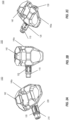
- Fig. 1A and Fig. 1B are diagrams illustrating exemplary power-measuring devices 100.
- the power-measuring device 100 includes a spindle 110, a spindle cover 120 coupled with the spindle 110, and at least an end cap 130 attached to one end of the spindle 110.
- the power-measuring device 100 may be coupled with a removable pedal (e.g., a pedal body 140a for cycling shoes with cleats) for cycling that is coupled with the spindle 110, and one or more pedal designs may be available.
- a removable pedal e.g., a pedal body 140a for cycling shoes with cleats
- different users or cyclists may opt for different pedals, pedal designs, or pedal systems, such as those of different brands, those with different mechanical designs or structures, and those work with different cleats or cycling shoes.
- the power-measuring device 100 shown in Fig. 1B the power-measuring device 100 is coupled with a different pedal body 140b, such as a flat pedal that is not restricted to a particular type or brand of shoes or shoe cleats.
- Figs. 2A-2C are diagrams illustrating different perspective views of the exemplary power-measuring device 100.
- the pedal body 140a includes a pedal plate 142, which can have one of various designs to work with shoes or shoe cleats of different brands, different mechanical designs or structures, or different riding conditions or applications.
- the spindle cover 120 is coupled with a portion of the spindle 110 and may be arranged to enclose at least a portion of one or more power gauges 210 (e.g., strain gauge) and/or an electrical circuit 220 electrically coupled with the power gauge 210.
- power gauges 210 e.g., strain gauge
- the electrical circuit 220 is coupled with the spindle 110 and electrically coupled with one or more battery units and configured to receive, process, read, or detect signals from the power gauge 210.
- the electrical circuit 220 includes a printed circuit board (PCB) or a flexible printed circuit (FPC) enclosed in a protective material under the cover.
- the power gauge 210 is coupled with the spindle 110 to measure the power transferring from an exerted force applied by a rider to the spindle 110 during pedaling.
- the end cap 130 may provide a locking mechanism to prevent the pedal body 140a from coming loose from the spindle 110.
- the pedal body 140a can be released from the spindle 110 only after the end cap 130 is removed.
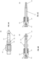
- Figs. 3A-3D are diagrams illustrating cross-section views of the exemplary power-measuring device 100.
- the spindle 110 is configured to provide a coupling with a driving unit.
- the driving unit may drive a bicycle, through pedaling of bicycle crank arms that are configured to receive power from a rider.
- the spindle 110 includes a battery chamber 112 within a hollow space of the spindle 110.
- the battery chamber 112 is configured to receive one or more battery units 310.
- the spindle cover 120 encloses at least a portion of at least one or more power gauges 210 and the PCB/FPC circuit 220.
- the PCB/FPC circuit 220 is coupled with one or more battery units 310 in the battery chamber 112.
- One or more bearing units 322, 324 may be mounted on, near, or within the spindle 110.
- the pedal body 140a or 140b may be coupled with the spindle 110 and the end cap 130 is attached to the pedal body 140a or 140b at one end of the spindle 110, to the spindle 110, or to both the spindle 110 and pedal body 140a or 140b.
- the battery chamber 112 is configured to enclose a single battery unit 310.
- the battery chamber 112 is configured to enclose multiple battery units 312, 314, 316 coupled in series or in parallel.
- the battery units 312, 314, 316 may include a plurality of button batteries or pin-type batteries connected in series or in parallel.
- the term "pin-type battery” or “pin-shaped battery” as used herein refers to a battery having a slim and cylindrical shape.
- the battery may be a rechargeable battery, such as a Lithium-ion (Li-Ion) battery.
- prismatic Li-Ion battery cells or pouch Li-Ion battery cells (soft pack) may also be used if the size of the battery cell is sufficiently small to fit into the battery chamber 112.
- the electrodes of the battery unit(s) are electrically coupled to the electrical circuit 220 via wiring, via spindle itself, or via both. And a set of wires 330 may pass through a hole 114 provided on the spindle 110 to couple the battery's electrodes to the electrical circuit 220.
- the electrical circuit 220 can be powered at least in part by the battery unit 310.
- the electrical circuit 220 may also be powered by the relative rotational movement between the spindle 110 and the pedal body 140a or 140b, by solar, or by a combination or alternation among two or more different kinds of power sources.
- arranging the battery unit 310 within a cylindrical space (e.g., battery chamber 112) inside the spindle 110 may significantly reduce the overall size of the power-measuring device 100, reducing the cost and/or providing a compact or streamlined design. In some embodiments, this design also brings more flexibility to the arrangement of power gauges 210 and the electrical circuit 220 enclosed in the spindle cover 120, because the battery unit 310 does not take up much space. In addition, protecting the battery unit 310 with the spindle 110 may prevent dust, water, grease, collision, and other concerns. Furthermore, larger battery components can be used without occupying additional space, which improves the device performance (e.g., longer time for cycling) and the user experience.
- Figs. 4A-4C are diagrams illustrating cross-section views of another exemplary power-measuring device 400. Similar to Figs. 3A-3D , the spindle 410 includes a battery chamber 412 for one or more battery units 310. The spindle cover 420 encloses at least a portion of one or more power gauges 210 and the PCB/FPC circuit 220. The PCB/FPC circuit 220 is electrically coupled with one or more battery units 310 in the battery chamber 412. One or more bearing units 322, 324 are mounted on the spindle 410.
- the pedal body (not shown) is coupled with the spindle 410 and the end cap (not shown) is attached to the pedal body at one end of the spindle 410, to the spindle 410, or to both.
- the battery chamber 412 is configured to store a single battery. In some embodiments, the battery chamber 412 is configured to store multiple batteries coupled in series or in parallel.
- the power-measuring device 400 also includes a sealing ring 430 arranged adjacent to the spindle cover 420 and configured to prevent water or dust from damaging the one or more power gauges 210 and/or PCB/FPC circuit 220 enclosed in the spindle cover 420.
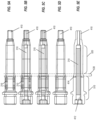
- the spindle 410 includes a first section 510 having a first outer diameter and a second section 520 having a second outer diameter, in which the second outer diameter is smaller than the first outer diameter.
- the battery chamber 412 extends through at least a portion of the first section 510 and at least a portion of the second section 520.
- the first and the second sections 510, 520 having similar inner diameters for providing the hollow space for the battery chamber 412 within the spindle 410. As shown in Figs.
- the power gauge 210 is mounted on or near the first section 510 of the spindle 410, and the spindle cover 420 is arranged to cover at least an area of the first section 510.
- the one or more bearing units 322, 324 are arranged on the second section 520.
- a hole 414 is provided on the spindle 410 between the first section 510 and the second section 520, and a transition section 530 couples between the first section 510 and the second section 520.
- the hole 414 is provided on the spindle 410 in the first section 510 with the greater outer diameter.
- the spindle 410 having two sections 510, 520 with different outer diameters can provide a structure distributing the stress evenly to withstand greater stress on the spindle 410 during the pedaling and prevent the spindle 410 from damages by the high stress distributed in an area near and/or around the hole 414 provided within the spindle 410 for the wiring.
- a length 610 of the transition section 530 along a longitudinal axis of the spindle 410 between approximately 1 and 6 millimeters.
- the length 610 of the transition section may be 1, 1.2, 1.4, 1.6, 1.8, 2.0, 2.2, 2.4, 2.6, 2.8, 3.0, 3.2, 3.4, 3.6, 3.8, 4.0, 4.2, 4.4, 4.6, 4.8, 5.0, 5.2, 5.4, 5.6, 5.8, or 6.0 mm, or any other practical number according to the actual design needs.
- the transition section 530 may have a surface with a straight slope (e.g., as shown in Fig. 6 ) or with a curve, such as a convex, a concave, or another shape with varying heights along the length of the section.
- the first outer diameter 620 of the first section 510 is approximately between 11-15 millimeters (e.g., 11, 11.5, 12, 12.5, 13, 13.5, 14, 14.5, or 15 mm, or any other practical number according to the actual design needs).
- the second outer diameter 630 of the second section 520 is between approximately 10 and 13 millimeters (e.g., 10, 10.5, 11, 11.5, 12, 12.5, or 13 mm, or any other practical number according to the actual design needs).
- a thickness 640 of a spindle wall surrounding the battery chamber 412 is between approximately 2 and 4 millimeters (e.g., 2, 2.2, 2.4, 2.6, 2.8, 3, 3.2, 3.4, 3.6, 3.8, or 4 mm, or any other practical number according to the actual design needs).
- a length 650 of the battery chamber 412 is between approximately 50 and 80 millimeters (e.g., 50, 55, 60, 65, 70, 75, or 80 mm, or any other practical number according to the actual design needs).
- a diameter 660 of the hole 414 through the spindle wall in the spindle 410 is between approximately 0.6 and 3 millimeters (e.g., 0.6, 0.8, 1.0, 1.2, 1.4, 1.6, 1.8, 2.0, 2.2, 2.4, 2.6, 2.8 or 3.0 mm, or any other practical number according to the actual design needs).
- a diameter 670 of the battery chamber 412 is between approximately 4.5 and 9 millimeters (e.g., 4.5, 5, 5.5, 6, 6.5, 7, 7.5, 8, 8.5, or 9 mm, or any other practical number according to the actual design needs).
- Figs. 7A and 7B illustrate stress distributions of two spindle designs (e.g., design 710 and design 720) with different parameters.
- Fig. 8 illustrates a comparison between stress values of design 710 and of design 720.
- the transition section 530 between the first section 510 and the second section 520 in design 710 is steeper (e.g., with a greater slope value) compared to the design 720.
- the length 610 of the transition section 530 may be selected to be within approximately 1-6 millimeters to adjust the slope value of the transition section 530 within a proper range to reduce the stress applied to the transition section 530.
- the transition section 530 with a greater length 610 may provide a lower slope value, thereby reducing the maximum stress value that occurs around the structure of the transition section 530 and next to the hole.
- the peak of the stress value in design 720 is significantly lower than the peak of the stress value in design 710, which indicates that the stress withstanding ability of the spindle 410 can be further improved by properly adjusting the slope value of the transition section 530, even if the spindle 410 is designed to have the hollow space for the battery chamber 412.
- the maximum stress value of design 710 is around 646 MPa in a test, which occurs at or near the connecting point between the transition section 530 and the second section 520.
- the transition section 530 of the design 720 is a milder slope, and the maximum stress value of design 720 is around 548 MPa under the same test condition.
- the slope of the transition section 530 can be determined based on parameter values including the first outer diameter 620, the second outer diameter 630, and the length 610 of the transition section 530
- the selection of the second outer diameter 630 is associated with the selection of the first outer diameter 620, to ensure the difference between the first outer diameter 620 and the second outer diameter 630 is within a threshold value, e.g., around or within 2 mm.
- the selection of the length 610 of the transition section 530 is associated with the difference between the first outer diameter 620 and the second outer diameter 630.
- the slope of the transition section 530 may be in the range of about 0° to 45° (e.g., 0°, 5°, 10°, 15°, 20°, 25°, 30°, 35°, 40°, 45°, or any other angle based on design needs or design choices).
- the first outer diameter 620 of 15 mm, the second outer diameter 630 of 13 mm, and the length 610 of 1 mm may provide a 45-degree slope.
- the slope of 0° indicates that the first section 510 at one side of the hole (e.g., hole 114 or hole 414) and the second section 520 at the other side of the hole have the same outer diameter without a sloped transition section (e.g., as shown in the design of the power-measuring device 100 in Figs. 3A-3D ).
- the spindle 410 may be designed with desired mechanical properties, strengths, or shapes. In other words, a selection or variation of these parameter values can adjust the mechanical force or repetitive loading spindle 410 can withstand and vary its ability to prevent force/load-induced damages.
- Figs. 9A-9C illustrate another exemplary power-measuring device 900.
- four sections 910 are configured for mounting power gauges.
- eight power gauges 210a-210h are placed on the four sections 910.
- the four sections 910 are equally spaced apart from one another around the first section 510. In other words, the angle between the center axes of two adjacent sections 910 is equal to or about 90 degrees.
- the hole 414 is provided on the first section 510 near an end adjacent to the transition section 530 and equally spaced between the two adjacent sections 910. In other words, the angle between the axis of the hole 414 and the center axis of the adjacent section 910 is equal to or about 45 degrees.
- each section 910 is associated with a pair of power gauges (e.g., a first pair including power gauges 210a and 210b, a second pair including power gauges 210c and 210d, a third pair including power gauges 210e and 210f, a fourth pair including power gauges 210g and 210h).
- Power gauges 210b, 210d, 210f, 210h are adjacent to the transition section 530, while power gauges 210a, 210c, 210e, 210g are away from the transition section 530.
- the sensing signals detected by power gauges 210b, 210d, 210f, 210h adjacent to the transition section 530 may be more imbalanced compared to the sensing signals detected by power gauges 210a, 210c, 210e, 210g due to the hole 414.
- Fig. 10 is a diagram illustrating an imbalanced detection result caused by the hole 414.
- a detecting point 1010 e.g., a detecting point corresponding to the power gauge 210h
- two forces F1 and F2 with the same value and equally distanced from the detecting point 1010 may result different detection results, because the force F2 is applied adjacent to the hollow hole 414 and on the same side with the detecting point 1010, while the force F1 is applied away from the hollow hole 414, and the hole 414 separates the detecting point 1010 from the force F1.
- the sensing signals detected may be imbalanced due to the hole 414, which causes an undesired error and leads to potential malfunction.
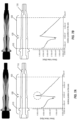
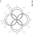
- Fig. 11A is a chart 1100a illustrating detection results obtained from a power-measuring device with a relatively large diameter of the hole.
- curves 1110, 1120, 1130, and 1140 respectively represent the sensitivities detected by power gauges 210a-210h.
- the curve 1110 represents the sensitivity detected by subtracting the signal detected by power gauge 210c from the signal detected by power gauge 210a.
- the curve 1120 represents the sensitivity detected by subtracting the signal detected by power gauge 210d from the signal detected by power gauge 210b.
- the curve 1130 represents the sensitivity detected by subtracting the signal detected by power gauge 210g from the signal detected by power gauge 210e.
- the curve 1140 represents the sensitivity detected by subtracting the signal detected by power gauge 210h from the signal detected by power gauge 210f. Each sample point represents the value of the sensitivity detected when the force is applied at a specific angle.
- Each of curves 1110, 1120, 1130, and 1140 includes 36 sample points associated with the detections performed every 10 degrees.
- the imbalanced errors exist between curves 1110-1140 and the ideally symmetric results denoted by the dotted lines.
- the imbalanced errors shown in the curves 1120 and 1140 corresponding to the power gauges 210b, 210d, 210f, and 210h closer to the hole 414 are greater than the imbalanced errors shown in the curves 1110 and 1130.
- Fig. 11B is another chart 1100b illustrating detection results obtained from a power-measuring device with a relatively small diameter of the hole. Similar to Fig. 11A , in Fig. 11B , curves 1150, 1160, 1170, and 1180 respectively represent the sensitivities detected by power gauges 210a-210h. In particular, the curve 1150 represents the sensitivity detected by subtracting the signal detected by power gauge 210c from the signal detected by power gauge 210a.
- the curve 1160 represents the sensitivity detected by subtracting the signal detected by power gauge 210d from the signal detected by power gauge 210b.
- the curve 1170 represents the sensitivity detected by subtracting the signal detected by power gauge 210g from the signal detected by power gauge 210e.
- the curve 1180 represents the sensitivity detected by subtracting the signal detected by power gauge 210h from the signal detected by power gauge 210f Compared to Fig. 11A , the imbalanced errors shown in curves 1150-1180 of Fig. 11B are less than the imbalanced errors shown in curves 1110-1140 of Fig. 11A due to the relatively small diameter (e.g., 1.2 mm) of the hole 414.
- the diameter 660 of the hole 414 through the spindle wall in the spindle 410 may be selected to meet the actual design needs. For example, the diameter 660 may be between approximately 0.6 and 3 millimeters.
- the term "or" encompasses all possible combinations, except where infeasible. For example, if it is stated that a database may include A or B, then, unless specifically stated otherwise or infeasible, the database may include A, or B, or A and B. As a second example, if it is stated that a database may include A, B, or C, then, unless specifically stated otherwise or infeasible, the database may include A, or B, or C, or A and B, or A and C, or B and C, or A and B and C.
Landscapes
- Engineering & Computer Science (AREA)
- Mechanical Engineering (AREA)
- Chemical & Material Sciences (AREA)
- Combustion & Propulsion (AREA)
- Transportation (AREA)
- Battery Mounting, Suspending (AREA)
- Measuring Fluid Pressure (AREA)
- Control Of Electric Motors In General (AREA)
- Measurement Of Current Or Voltage (AREA)
- Length-Measuring Instruments Using Mechanical Means (AREA)
Abstract
Description
- This disclosure relates to bicycles and power-measuring devices for the bicycles.
- A bicycle power-measuring device, also known as a power meter to some, is a device for measuring a rider's pedaling power during cycling. The pedaling power can be measured in the form of or converted or computed from the torque level a rider exerts in driving bike pedals and/or crank arms. For example, a bicycle power-measuring device can be one or more strain gauges in one or both cranks or within one of both pedals. A deformation of a measuring device or gauge varies according to the amount of force applied. The change in strain characteristic or deformation of the strain gauge can then be measured, processed, and/or converted to derive the pedaling torque.
- However, a conventional bicycle power-measuring device needs various components that can take up a lot of space, which increases the overall size, weight, and/or placement of the power-measuring device. Furthermore, all the moving parts may be subject to water, physical impacts, dusts, mud, and/or weather conditions, which may impact the operability, accuracy, and reliability of the device.
- One aspect of the present application provides a power-measuring device which includes a spindle, a power gauge, an electrical circuit, and a cover. The spindle is configured to provide a coupling with a driving unit. The spindle includes a battery chamber within a hollow space of the spindle. The battery chamber is configured to receive a battery unit. The power gauge is coupled with the spindle to measure power applied to the spindle for driving a movement of the driving unit. The electrical circuit is electrically coupled with the power gauge. The electrical circuit is coupled with the battery and configured to receive and process signals from the power gauge. The cover is coupled with the spindle and arranged to enclose at least a portion of at least one of the power gauge and the electrical circuit.
- Another aspect of the present disclosure provides a bicycle includes crank arms configured to receive power from a rider, a driving unit configured to drive the bicycle through pedaling of the crank arms; and a power-measuring device. The power-measuring device includes a spindle, a power gauge, an electrical circuit, and a cover. The spindle is configured to provide a coupling with a driving unit. The spindle includes a battery chamber within a hollow space of the spindle. The battery chamber is configured to receive a battery unit. The power gauge is coupled with the spindle to measure power applied to the spindle for driving a movement of the driving unit. The electrical circuit is electrically coupled with the power gauge. The electrical circuit is coupled with the battery and configured to receive and process signals from the power gauge. The cover is coupled with the spindle and arranged to enclose at least a portion of at least one of the power gauge and the electrical circuit.
- A further aspect of the present disclosure provides a spindle which includes: a first section having a first outer diameter, a second section having a second outer diameter smaller than the first outer diameter, a transition section coupled between the first section and the second section, and a battery chamber within a hollow space of the spindle, the battery chamber being configured to receive a battery unit. The battery chamber extends through at least a portion of the first section and at least a portion of the second section. The first section and the second section have similar inner diameters for providing the hollow space for the battery chamber within the spindle. A hole is provided on the spindle between the first section and the second section.
- The accompanying drawings, which are incorporated in and constitute a part of this specification, illustrate several exemplary embodiments and, together with the corresponding descriptions, provide examples for explaining the disclosed embodiments and related principles.
-
Fig. 1A and Fig. 1B illustrate exemplary power-measuring devices. -
Figs. 2A-2C illustrate various views of the exemplary power-measuring device. -
Figs. 3A-3D illustrate cross-section views of an exemplary power-measuring device. -
Figs. 4A-4C illustrate cross-section views of another exemplary power-measuring device. -
Figs. 5A-5E illustrate cross sectional views of the power-measuring device ofFigs. 4A-4C . -
Fig. 6 illustrates a cross sectional view of the power-measuring device ofFigs. 4A-4C . -
Figs. 7A and 7B illustrate examples of stress distributions of two spindle designs. -
Fig. 8 illustrates a comparison between stress values of two exemplary designs. -
Figs. 9A-9C illustrate another exemplary power-measuring device. -
Fig. 10 is a diagram illustrating an imbalanced detection result. -
Figs. 11A and11B are charts respectively illustrating detection results obtained from different power-measuring devices. - Reference will now be made in detail to exemplary embodiments, examples of which are illustrated in the accompanying drawings and disclosed herein. The implementations set forth in the following description of exemplary embodiments are examples of systems and methods consistent with the aspects related to the disclosure and consistent with those recited in the appended claims. However, the following descriptions should not and do not limit the scope of the present disclosure.
-
Fig. 1A and Fig. 1B are diagrams illustrating exemplary power-measuring devices 100. As shown inFig. 1A , the power-measuring device 100 includes aspindle 110, aspindle cover 120 coupled with thespindle 110, and at least anend cap 130 attached to one end of thespindle 110. In some embodiments, the power-measuring device 100 may be coupled with a removable pedal (e.g., apedal body 140a for cycling shoes with cleats) for cycling that is coupled with thespindle 110, and one or more pedal designs may be available. In some other embodiments, different users or cyclists may opt for different pedals, pedal designs, or pedal systems, such as those of different brands, those with different mechanical designs or structures, and those work with different cleats or cycling shoes. In the power-measuringdevice 100 shown inFig. 1B , the power-measuringdevice 100 is coupled with a differentpedal body 140b, such as a flat pedal that is not restricted to a particular type or brand of shoes or shoe cleats. -
Figs. 2A-2C are diagrams illustrating different perspective views of the exemplary power-measuringdevice 100. In the power-measuringdevice 100 shown inFigs. 2A-2C , thepedal body 140a includes apedal plate 142, which can have one of various designs to work with shoes or shoe cleats of different brands, different mechanical designs or structures, or different riding conditions or applications. As shown inFigs. 2A-2C , thespindle cover 120 is coupled with a portion of thespindle 110 and may be arranged to enclose at least a portion of one or more power gauges 210 (e.g., strain gauge) and/or anelectrical circuit 220 electrically coupled with thepower gauge 210. Theelectrical circuit 220 is coupled with thespindle 110 and electrically coupled with one or more battery units and configured to receive, process, read, or detect signals from thepower gauge 210. In some embodiments, theelectrical circuit 220 includes a printed circuit board (PCB) or a flexible printed circuit (FPC) enclosed in a protective material under the cover. Thepower gauge 210 is coupled with thespindle 110 to measure the power transferring from an exerted force applied by a rider to thespindle 110 during pedaling. As shown inFIG. 2C , theend cap 130 may provide a locking mechanism to prevent thepedal body 140a from coming loose from thespindle 110. In some embodiments, thepedal body 140a can be released from thespindle 110 only after theend cap 130 is removed. -
Figs. 3A-3D are diagrams illustrating cross-section views of the exemplary power-measuringdevice 100. As shown inFigs. 3A-3D , thespindle 110 is configured to provide a coupling with a driving unit. For example, the driving unit may drive a bicycle, through pedaling of bicycle crank arms that are configured to receive power from a rider. Thespindle 110 includes abattery chamber 112 within a hollow space of thespindle 110. Thebattery chamber 112 is configured to receive one ormore battery units 310. Thespindle cover 120 encloses at least a portion of at least one or more power gauges 210 and the PCB/FPC circuit 220. The PCB/FPC circuit 220 is coupled with one ormore battery units 310 in thebattery chamber 112. One or morebearing units spindle 110. Thepedal body spindle 110 and theend cap 130 is attached to thepedal body spindle 110, to thespindle 110, or to both thespindle 110 andpedal body battery chamber 112 is configured to enclose asingle battery unit 310. In some embodiments, as shown inFigs. 3C and 3D , thebattery chamber 112 is configured to enclosemultiple battery units battery units battery chamber 112. - The electrodes of the battery unit(s) are electrically coupled to the
electrical circuit 220 via wiring, via spindle itself, or via both. And a set ofwires 330 may pass through ahole 114 provided on thespindle 110 to couple the battery's electrodes to theelectrical circuit 220. Theelectrical circuit 220 can be powered at least in part by thebattery unit 310. Theelectrical circuit 220 may also be powered by the relative rotational movement between thespindle 110 and thepedal body - In various embodiments, arranging the
battery unit 310 within a cylindrical space (e.g., battery chamber 112) inside thespindle 110 may significantly reduce the overall size of the power-measuringdevice 100, reducing the cost and/or providing a compact or streamlined design. In some embodiments, this design also brings more flexibility to the arrangement of power gauges 210 and theelectrical circuit 220 enclosed in thespindle cover 120, because thebattery unit 310 does not take up much space. In addition, protecting thebattery unit 310 with thespindle 110 may prevent dust, water, grease, collision, and other concerns. Furthermore, larger battery components can be used without occupying additional space, which improves the device performance (e.g., longer time for cycling) and the user experience. -
Figs. 4A-4C are diagrams illustrating cross-section views of another exemplary power-measuringdevice 400. Similar toFigs. 3A-3D , thespindle 410 includes abattery chamber 412 for one ormore battery units 310. Thespindle cover 420 encloses at least a portion of one or more power gauges 210 and the PCB/FPC circuit 220. The PCB/FPC circuit 220 is electrically coupled with one ormore battery units 310 in thebattery chamber 412. One or morebearing units spindle 410. The pedal body (not shown) is coupled with thespindle 410 and the end cap (not shown) is attached to the pedal body at one end of thespindle 410, to thespindle 410, or to both. In some embodiments, thebattery chamber 412 is configured to store a single battery. In some embodiments, thebattery chamber 412 is configured to store multiple batteries coupled in series or in parallel. In some embodiments, the power-measuringdevice 400 also includes asealing ring 430 arranged adjacent to thespindle cover 420 and configured to prevent water or dust from damaging the one or more power gauges 210 and/or PCB/FPC circuit 220 enclosed in thespindle cover 420. -
Figs. 3A-3D andFigs. 4A-4C show two different types of thespindle Figs. 4A-4C andFigs. 5A-5E , thespindle 410 includes afirst section 510 having a first outer diameter and asecond section 520 having a second outer diameter, in which the second outer diameter is smaller than the first outer diameter. Thebattery chamber 412 extends through at least a portion of thefirst section 510 and at least a portion of thesecond section 520. The first and thesecond sections battery chamber 412 within thespindle 410. As shown inFigs. 4A-4C , thepower gauge 210 is mounted on or near thefirst section 510 of thespindle 410, and thespindle cover 420 is arranged to cover at least an area of thefirst section 510. The one ormore bearing units second section 520. - As shown in
Figs. 4A-4C andFigs. 5A-5E , ahole 414 is provided on thespindle 410 between thefirst section 510 and thesecond section 520, and atransition section 530 couples between thefirst section 510 and thesecond section 520. Particularly, thehole 414 is provided on thespindle 410 in thefirst section 510 with the greater outer diameter. - In some embodiments, the
spindle 410 having twosections spindle 410 during the pedaling and prevent thespindle 410 from damages by the high stress distributed in an area near and/or around thehole 414 provided within thespindle 410 for the wiring. - As shown in
Fig. 6 , in some embodiments, alength 610 of thetransition section 530 along a longitudinal axis of thespindle 410 between approximately 1 and 6 millimeters. For example, thelength 610 of the transition section may be 1, 1.2, 1.4, 1.6, 1.8, 2.0, 2.2, 2.4, 2.6, 2.8, 3.0, 3.2, 3.4, 3.6, 3.8, 4.0, 4.2, 4.4, 4.6, 4.8, 5.0, 5.2, 5.4, 5.6, 5.8, or 6.0 mm, or any other practical number according to the actual design needs. In some embodiments, thetransition section 530 may have a surface with a straight slope (e.g., as shown inFig. 6 ) or with a curve, such as a convex, a concave, or another shape with varying heights along the length of the section. - As shown in
Fig. 6 , in some embodiments, the firstouter diameter 620 of thefirst section 510 is approximately between 11-15 millimeters (e.g., 11, 11.5, 12, 12.5, 13, 13.5, 14, 14.5, or 15 mm, or any other practical number according to the actual design needs). - As shown in
Fig. 6 , in some embodiments, the secondouter diameter 630 of thesecond section 520 is between approximately 10 and 13 millimeters (e.g., 10, 10.5, 11, 11.5, 12, 12.5, or 13 mm, or any other practical number according to the actual design needs). - As shown in
Fig. 6 , in some embodiments, athickness 640 of a spindle wall surrounding thebattery chamber 412 is between approximately 2 and 4 millimeters (e.g., 2, 2.2, 2.4, 2.6, 2.8, 3, 3.2, 3.4, 3.6, 3.8, or 4 mm, or any other practical number according to the actual design needs). - As shown in
Fig. 6 , in some embodiments, alength 650 of thebattery chamber 412 is between approximately 50 and 80 millimeters (e.g., 50, 55, 60, 65, 70, 75, or 80 mm, or any other practical number according to the actual design needs). - As shown in
Fig. 6 , in some embodiments, adiameter 660 of thehole 414 through the spindle wall in thespindle 410 is between approximately 0.6 and 3 millimeters (e.g., 0.6, 0.8, 1.0, 1.2, 1.4, 1.6, 1.8, 2.0, 2.2, 2.4, 2.6, 2.8 or 3.0 mm, or any other practical number according to the actual design needs). - As shown in
Fig. 6 , in some embodiments, adiameter 670 of thebattery chamber 412 is between approximately 4.5 and 9 millimeters (e.g., 4.5, 5, 5.5, 6, 6.5, 7, 7.5, 8, 8.5, or 9 mm, or any other practical number according to the actual design needs). -
Figs. 7A and 7B illustrate stress distributions of two spindle designs (e.g.,design 710 and design 720) with different parameters.Fig. 8 illustrates a comparison between stress values ofdesign 710 and ofdesign 720. As shown inFigs. 7A and 7B , thetransition section 530 between thefirst section 510 and thesecond section 520 indesign 710 is steeper (e.g., with a greater slope value) compared to thedesign 720. As discussed inFig. 6 above, thelength 610 of thetransition section 530 may be selected to be within approximately 1-6 millimeters to adjust the slope value of thetransition section 530 within a proper range to reduce the stress applied to thetransition section 530. Particularly, thetransition section 530 with agreater length 610 may provide a lower slope value, thereby reducing the maximum stress value that occurs around the structure of thetransition section 530 and next to the hole. As shown inFigs. 7A and 7B , the peak of the stress value indesign 720 is significantly lower than the peak of the stress value indesign 710, which indicates that the stress withstanding ability of thespindle 410 can be further improved by properly adjusting the slope value of thetransition section 530, even if thespindle 410 is designed to have the hollow space for thebattery chamber 412. In one example, the maximum stress value ofdesign 710 is around 646 MPa in a test, which occurs at or near the connecting point between thetransition section 530 and thesecond section 520. On the other hand, thetransition section 530 of thedesign 720 is a milder slope, and the maximum stress value ofdesign 720 is around 548 MPa under the same test condition. - Because the slope of the
transition section 530 can be determined based on parameter values including the firstouter diameter 620, the secondouter diameter 630, and thelength 610 of thetransition section 530, in some embodiments, the selection of the secondouter diameter 630 is associated with the selection of the firstouter diameter 620, to ensure the difference between the firstouter diameter 620 and the secondouter diameter 630 is within a threshold value, e.g., around or within 2 mm. Alternatively, the selection of thelength 610 of thetransition section 530 is associated with the difference between the firstouter diameter 620 and the secondouter diameter 630. In some embodiments, the slope of thetransition section 530 may be in the range of about 0° to 45° (e.g., 0°, 5°, 10°, 15°, 20°, 25°, 30°, 35°, 40°, 45°, or any other angle based on design needs or design choices). For example, the firstouter diameter 620 of 15 mm, the secondouter diameter 630 of 13 mm, and thelength 610 of 1 mm may provide a 45-degree slope. The slope of 0° indicates that thefirst section 510 at one side of the hole (e.g.,hole 114 or hole 414) and thesecond section 520 at the other side of the hole have the same outer diameter without a sloped transition section (e.g., as shown in the design of the power-measuringdevice 100 inFigs. 3A-3D ). By designing a relativelymild transition section 530, thespindle 410 may be designed with desired mechanical properties, strengths, or shapes. In other words, a selection or variation of these parameter values can adjust the mechanical force orrepetitive loading spindle 410 can withstand and vary its ability to prevent force/load-induced damages. -
Figs. 9A-9C illustrate another exemplary power-measuringdevice 900. In the embodiments ofFigs. 9A-9C , foursections 910 are configured for mounting power gauges. Specifically, eightpower gauges 210a-210h are placed on the foursections 910. As shown inFIG. 9A , the foursections 910 are equally spaced apart from one another around thefirst section 510. In other words, the angle between the center axes of twoadjacent sections 910 is equal to or about 90 degrees. Thehole 414 is provided on thefirst section 510 near an end adjacent to thetransition section 530 and equally spaced between the twoadjacent sections 910. In other words, the angle between the axis of thehole 414 and the center axis of theadjacent section 910 is equal to or about 45 degrees. - As shown in
Fig. 9B andFig. 9C , eachsection 910 is associated with a pair of power gauges (e.g., a first pair includingpower gauges power gauges transition section 530, while power gauges 210a, 210c, 210e, 210g are away from thetransition section 530. During the pedaling, the sensing signals detected bypower gauges transition section 530 may be more imbalanced compared to the sensing signals detected bypower gauges hole 414. -
Fig. 10 is a diagram illustrating an imbalanced detection result caused by thehole 414. As shown inFig. 10 , for the same detecting point 1010 (e.g., a detecting point corresponding to thepower gauge 210h), two forces F1 and F2 with the same value and equally distanced from the detectingpoint 1010 may result different detection results, because the force F2 is applied adjacent to thehollow hole 414 and on the same side with the detectingpoint 1010, while the force F1 is applied away from thehollow hole 414, and thehole 414 separates the detectingpoint 1010 from the force F1. As a result, the sensing signals detected may be imbalanced due to thehole 414, which causes an undesired error and leads to potential malfunction. -
Fig. 11A is achart 1100a illustrating detection results obtained from a power-measuring device with a relatively large diameter of the hole. As shown inFig. 11A , curves 1110, 1120, 1130, and 1140 respectively represent the sensitivities detected bypower gauges 210a-210h. In particular, thecurve 1110 represents the sensitivity detected by subtracting the signal detected bypower gauge 210c from the signal detected bypower gauge 210a. Similarly, thecurve 1120 represents the sensitivity detected by subtracting the signal detected bypower gauge 210d from the signal detected bypower gauge 210b. Thecurve 1130 represents the sensitivity detected by subtracting the signal detected bypower gauge 210g from the signal detected bypower gauge 210e. Thecurve 1140 represents the sensitivity detected by subtracting the signal detected bypower gauge 210h from the signal detected bypower gauge 210f. Each sample point represents the value of the sensitivity detected when the force is applied at a specific angle. Each ofcurves Fig. 11A , the imbalanced errors exist between curves 1110-1140 and the ideally symmetric results denoted by the dotted lines. In addition, the imbalanced errors shown in thecurves hole 414 are greater than the imbalanced errors shown in thecurves - By properly selecting the
diameter 660 of thehole 414, the imbalanced errors can be reduced. In particular, when thediameter 660 is reduced, the errors can be reduced accordingly as thehole 414 causes less impact on the detection performed bypower gauges 210a-210h.Fig. 11B is anotherchart 1100b illustrating detection results obtained from a power-measuring device with a relatively small diameter of the hole. Similar toFig. 11A , inFig. 11B ,curves power gauges 210a-210h. In particular, thecurve 1150 represents the sensitivity detected by subtracting the signal detected bypower gauge 210c from the signal detected bypower gauge 210a. Similarly, thecurve 1160 represents the sensitivity detected by subtracting the signal detected bypower gauge 210d from the signal detected bypower gauge 210b. Thecurve 1170 represents the sensitivity detected by subtracting the signal detected bypower gauge 210g from the signal detected bypower gauge 210e. Thecurve 1180 represents the sensitivity detected by subtracting the signal detected bypower gauge 210h from the signal detected bypower gauge 210f Compared toFig. 11A , the imbalanced errors shown in curves 1150-1180 ofFig. 11B are less than the imbalanced errors shown in curves 1110-1140 ofFig. 11A due to the relatively small diameter (e.g., 1.2 mm) of thehole 414. As discussed above, in various embodiments, thediameter 660 of thehole 414 through the spindle wall in thespindle 410 may be selected to meet the actual design needs. For example, thediameter 660 may be between approximately 0.6 and 3 millimeters. - As used herein, unless specifically stated otherwise, the term "or" encompasses all possible combinations, except where infeasible. For example, if it is stated that a database may include A or B, then, unless specifically stated otherwise or infeasible, the database may include A, or B, or A and B. As a second example, if it is stated that a database may include A, B, or C, then, unless specifically stated otherwise or infeasible, the database may include A, or B, or C, or A and B, or A and C, or B and C, or A and B and C.
- The drawings and specification illustrate exemplary embodiments. It will be apparent to those skilled in the art that various modifications and variations can be made to the disclosed systems and related methods. Other embodiments will be apparent to those skilled in the art from considering the specification and applying the disclosed system and related methods.
Claims (15)
- A power-measuring device (100) comprising:a spindle (110,410) configured to provide a coupling with a driving unit, the spindle (110,410) including a battery chamber (112,412) within a hollow space of the spindle (110,410), the battery chamber (112,412) being configured to receive a battery unit (310);a power gauge (210) coupled with the spindle (110) to measure power applied to the spindle (110) for driving a movement of the driving unit;an electrical circuit (220) coupled with the spindle (110,410), the electrical circuit (220) being electrically coupled with the power gauge (210), being electrically coupled with the battery unit (310), and being configured to receive and process signals from the power gauge (210); anda cover (120) coupled with the spindle (110,410) and being arranged to enclose at least a portion of at least one of the power gauge (210) and the electrical circuit (220).
- The power-measuring device (100) of claim 1, wherein a hole (414) is provided on the spindle (110, 410).
- The power-measuring device (100) of claim 2, wherein the battery unit (310) is electrically coupled to the electrical circuit (220) via a set of wires that pass through the hole (414) provided on the spindle (110,410).
- The power-measuring device (100) of claim 2 or 3, wherein a diameter of the hole (414) through a spindle wall in the spindle (110,410) is between approximately 0.6 and 3 millimeters.
- The power-measuring device (100) of any of claims 1-4, wherein the spindle comprises a first section (510) having a first outer diameter and a second section (520) having a second outer diameter, the second outer diameter being smaller than the first outer diameter.
- The power-measuring device (100) of claim 5, wherein the battery chamber (112,412) extends through at least a portion of the first section (510) and at least a portion of the second section (520), the first and the second sections (510,520) having similar inner diameters for providing the hollow space for the battery chamber (112,412) within the spindle (110).
- The power-measuring device (100) of claim 5 or 6, wherein the power gauge (210) is mounted on or near the first section (510) of the spindle (110), and the cover (120) is arranged to cover at least an area of the first section (510).
- The power-measuring device (100) of any of claims 5-7, when dependent upon claim 2, wherein either the hole (414) is provided on the spindle (110,410) in the first section (510) or the hole (414) is provided on the spindle (110,410) between the first and the second sections (510,520) of the spindle (110,410), and wherein a transition section (530) couples between the first (510) and the second sections (520) of the spindle (110,410), and preferably wherein a length of the transition section (530) along a longitudinal axis of the spindle (110,410) is between approximately 1 and 6 millimeters.
- The power-measuring device (100) of any of claims 4-8, wherein the first outer diameter of the first section (510) of the spindle (110,410) is between approximately 11 and 15 millimeters.
- The power-measuring device (100) of any of claims 4-9, wherein the second outer diameter of the second section (520) of the spindle is between approximately 10 and 13 millimeters.
- The power-measuring device (100) of any preceding claim, wherein a thickness of a spindle wall surrounding the battery chamber (112,412) is between approximately 2 and 4 millimeters.
- The power-measuring device (100) of any preceding claim, wherein a length of the battery chamber (112,412) within the spindle (110,410) is between approximately 50 and 80 millimeters.
- The power-measuring device (100) of any preceding claim, wherein a diameter of the battery chamber (112,412) is between approximately 4.5 and 9 millimeters.
- A bicycle comprising:crank arms configured to receive power from a rider;a driving unit configured to drive the bicycle through pedaling of the crank arms; anda power-measuring device (100) in accordance with any preceding claim.
- A spindle (410) comprising:a first section (510) having a first outer diameter;a second section (520) having a second outer diameter, the second outer diameter being smaller than the first outer diameter;a transition section (530) coupled between the first section and the second section; anda battery chamber (412) within a hollow space of the spindle (410), the battery chamber (412) being configured to receive a battery unit (310), wherein the battery chamber (412) extends through at least a portion of the first section (510) and at least a portion of the second section (520) , the first section (510) and the second section (520) having similar inner diameters for providing the hollow space for the battery chamber (412) within the spindle (410);wherein a hole (414) is provided on the spindle between the first section (510) and the second section (512).
Applications Claiming Priority (2)
| Application Number | Priority Date | Filing Date | Title |
|---|---|---|---|
| US202163264833P | 2021-12-02 | 2021-12-02 | |
| US18/058,744 US12420882B2 (en) | 2021-12-02 | 2022-11-24 | Power-measuring devices |
Publications (1)
| Publication Number | Publication Date |
|---|---|
| EP4190680A1 true EP4190680A1 (en) | 2023-06-07 |
Family
ID=84367528
Family Applications (1)
| Application Number | Title | Priority Date | Filing Date |
|---|---|---|---|
| EP22210624.7A Pending EP4190680A1 (en) | 2021-12-02 | 2022-11-30 | Power-measuring devices |
Country Status (8)
| Country | Link |
|---|---|
| US (1) | US12420882B2 (en) |
| EP (1) | EP4190680A1 (en) |
| JP (1) | JP3240757U (en) |
| KR (1) | KR20230001180U (en) |
| CN (1) | CN218865334U (en) |
| AU (1) | AU2022279470B2 (en) |
| CA (1) | CA3182841C (en) |
| TW (1) | TWI847402B (en) |
Families Citing this family (1)
| Publication number | Priority date | Publication date | Assignee | Title |
|---|---|---|---|---|
| TWM632070U (en) * | 2021-11-04 | 2022-09-21 | 光旴科技股份有限公司 | Exercise signal detection device of electric brush pedal |
Citations (3)
| Publication number | Priority date | Publication date | Assignee | Title |
|---|---|---|---|---|
| FR3078158A1 (en) * | 2018-02-19 | 2019-08-23 | Ingenieurburo Schoberer Gmbh | ON-BOARD MEASURING DEVICE FOR MEASURING EFFORTS ON A CYCLE PEDAL AND CYCLE PROVIDED WITH SUCH A MEASURING DEVICE |
| WO2021028845A1 (en) * | 2019-08-12 | 2021-02-18 | Favero Electronics S.r.l. | Pedal for bicycles |
| WO2021234466A1 (en) * | 2020-05-21 | 2021-11-25 | Favero Electronics S.r.l. | Pedal for bicycles |
Family Cites Families (7)
| Publication number | Priority date | Publication date | Assignee | Title |
|---|---|---|---|---|
| FR2950428B1 (en) | 2009-09-22 | 2012-12-28 | Look Cycle Int | ON-CYCLE MEASURING DEVICE FOR EFFORTS MEASUREMENT AND CYCLE EQUIPPED WITH SUCH A MEASURING DEVICE |
| US8881608B2 (en) * | 2012-03-07 | 2014-11-11 | Shimano Inc. | Bicycle crank arm |
| US10000249B2 (en) | 2014-08-22 | 2018-06-19 | Shimano Inc. | Bicycle pedal |
| IT201900022536A1 (en) | 2019-11-29 | 2021-05-29 | Favero Electronics S R L | PEDAL FOR BICYCLES |
| US11511826B2 (en) | 2019-12-09 | 2022-11-29 | Sram, Llc | Bicycle axle assembly including a power meter |
| US11001327B1 (en) * | 2020-02-19 | 2021-05-11 | Sram, Llc | Pedal detection devices for bicycles |
| TWM624737U (en) * | 2021-10-22 | 2022-03-21 | 維格工業股份有限公司 | power pedal |
-
2022
- 2022-11-24 US US18/058,744 patent/US12420882B2/en active Active
- 2022-11-29 CA CA3182841A patent/CA3182841C/en active Active
- 2022-11-30 AU AU2022279470A patent/AU2022279470B2/en active Active
- 2022-11-30 EP EP22210624.7A patent/EP4190680A1/en active Pending
- 2022-12-01 TW TW111146233A patent/TWI847402B/en active
- 2022-12-01 KR KR2020220002828U patent/KR20230001180U/en active Pending
- 2022-12-02 JP JP2022003982U patent/JP3240757U/en active Active
- 2022-12-02 CN CN202223227206.7U patent/CN218865334U/en active Active
Patent Citations (3)
| Publication number | Priority date | Publication date | Assignee | Title |
|---|---|---|---|---|
| FR3078158A1 (en) * | 2018-02-19 | 2019-08-23 | Ingenieurburo Schoberer Gmbh | ON-BOARD MEASURING DEVICE FOR MEASURING EFFORTS ON A CYCLE PEDAL AND CYCLE PROVIDED WITH SUCH A MEASURING DEVICE |
| WO2021028845A1 (en) * | 2019-08-12 | 2021-02-18 | Favero Electronics S.r.l. | Pedal for bicycles |
| WO2021234466A1 (en) * | 2020-05-21 | 2021-11-25 | Favero Electronics S.r.l. | Pedal for bicycles |
Also Published As
| Publication number | Publication date |
|---|---|
| TW202334620A (en) | 2023-09-01 |
| JP3240757U (en) | 2023-02-01 |
| TWI847402B (en) | 2024-07-01 |
| AU2022279470B2 (en) | 2025-01-30 |
| US12420882B2 (en) | 2025-09-23 |
| CA3182841A1 (en) | 2023-06-02 |
| AU2022279470A1 (en) | 2023-06-22 |
| CA3182841C (en) | 2026-04-21 |
| CN218865334U (en) | 2023-04-14 |
| US20230174185A1 (en) | 2023-06-08 |
| KR20230001180U (en) | 2023-06-09 |
Similar Documents
| Publication | Publication Date | Title |
|---|---|---|
| EP2474343B1 (en) | Crankset based bicycle power measurement | |
| CN105383631A (en) | Bicycle pedal | |
| US8006574B2 (en) | Crankset based bicycle power measurement | |
| EP2304403B1 (en) | System and device for measuring and analyzing forces applied by a cyclist on a pedal of a bicycle | |
| US8453521B2 (en) | Bicycle force sensing device | |
| US8746081B2 (en) | Bicycle force sensing assembly | |
| US20100263468A1 (en) | Crank arm with strain amplifier | |
| US20140200835A1 (en) | Pedaling Torque Sensor Device for Each Cyclist's Leg and Power Meter Apparatus | |
| EP4190680A1 (en) | Power-measuring devices | |
| EP2890962B1 (en) | Apparatus and method for power measurement at a crank axle and crank arm | |
| EP4081447B1 (en) | Pedal for bicycles | |
| CN101279630A (en) | Instrumented bicycle component and detection unit for equipping the same | |
| US20200102036A1 (en) | Direct force measurement device for crank | |
| US20140000361A1 (en) | Sensor apparatus for determining forces applied to a pedal of a bicycle | |
| US11738825B2 (en) | Power pedal | |
| US10788383B2 (en) | Power vector sensor device and bicycle having the same | |
| DE202022105970U1 (en) | power measurement devices | |
| JP2567408B2 (en) | Engine shared load measuring method | |
| TW202545774A (en) | Crank arm for a human-powered vehicle |
Legal Events
| Date | Code | Title | Description |
|---|---|---|---|
| PUAI | Public reference made under article 153(3) epc to a published international application that has entered the european phase |
Free format text: ORIGINAL CODE: 0009012 |
|
| STAA | Information on the status of an ep patent application or granted ep patent |
Free format text: STATUS: THE APPLICATION HAS BEEN PUBLISHED |
|
| AK | Designated contracting states |
Kind code of ref document: A1 Designated state(s): AL AT BE BG CH CY CZ DE DK EE ES FI FR GB GR HR HU IE IS IT LI LT LU LV MC ME MK MT NL NO PL PT RO RS SE SI SK SM TR |
|
| STAA | Information on the status of an ep patent application or granted ep patent |
Free format text: STATUS: REQUEST FOR EXAMINATION WAS MADE |
|
| 17P | Request for examination filed |
Effective date: 20231207 |
|
| RBV | Designated contracting states (corrected) |
Designated state(s): AL AT BE BG CH CY CZ DE DK EE ES FI FR GB GR HR HU IE IS IT LI LT LU LV MC ME MK MT NL NO PL PT RO RS SE SI SK SM TR |
|
| STAA | Information on the status of an ep patent application or granted ep patent |
Free format text: STATUS: EXAMINATION IS IN PROGRESS |
|
| 17Q | First examination report despatched |
Effective date: 20250528 |