EP4190665A1 - Load locking system, especially on freight wagons - Google Patents
Load locking system, especially on freight wagons Download PDFInfo
- Publication number
- EP4190665A1 EP4190665A1 EP22187355.7A EP22187355A EP4190665A1 EP 4190665 A1 EP4190665 A1 EP 4190665A1 EP 22187355 A EP22187355 A EP 22187355A EP 4190665 A1 EP4190665 A1 EP 4190665A1
- Authority
- EP
- European Patent Office
- Prior art keywords
- trough
- load
- locking
- power supply
- arms
- Prior art date
- Legal status (The legal status is an assumption and is not a legal conclusion. Google has not performed a legal analysis and makes no representation as to the accuracy of the status listed.)
- Granted
Links
Images


Classifications
-
- B—PERFORMING OPERATIONS; TRANSPORTING
- B61—RAILWAYS
- B61D—BODY DETAILS OR KINDS OF RAILWAY VEHICLES
- B61D45/00—Means or devices for securing or supporting the cargo, including protection against shocks
- B61D45/001—Devices for fixing to walls or floors
- B61D45/003—Fixing of logs, beams, barrels, pipes, or the like
Definitions
- the subject of the invention is a system for locking loads, especially on railway wagons, intended in particular for locking coil-shaped loads.
- the Polish patent PL222981 (B1 ) describes a load locking device on freight wagons, having a pressure arm mounted in a rotational and movable way on a guide pipe, to which a propeller with a shaped tip and a spin wheel mounted on it are placed in parallel.
- On the propeller in the cutout of the pressure arm, there is a threaded part of the driver in the form of a half-nut with a control cam.
- the lower part of the driver there is a cutout in the shape of an inverted U letter, the arch of which is threaded and located between the arms blocking its rotation on the guide.
- the upper part of the driver is formed into a hook placed on the control cam provided with the control cam lever.
- the essence of the invention consists in the fact that the load blocking system, especially on freight wagons equipped with troughs, consists of:
- the electric motors are stepper motors.
- the electric motors are integrated with a common independent power supply system.
- the electric motors assigned to a single trough are connected to a local control unit coupled to at least one ultrasonic sensor for each trough that detects the load in the trough.
- the ultrasonic sensor is located in the middle of the wagon trough.
- the electronic control system in addition to ultrasonic sensors, consists of local control units, control panels and a central control unit responsible for sequential advancing and retracting the locking arms in successive troughs.
- the independent power supply system consists of a generator, a battery and a charge controller.
- the generator is mounted in the axle box of the wagon wheelset.
- the propellers and the cooperating nuts mechanically connected to the locking arms are equipped with a self-locking thread.
- the opposite end of the propeller is equipped with a shaped tip for connecting the emergency drive.
- the main advantage of the device according to the invention is the stepless system of moving the locking arms together with the electronic control system, which makes it possible to block the load placed anywhere in the trough.
- the device enables automatic moving of the locking arms to contact with the load or to a predetermined distance from the load specified by the device operator.
- Ultrasonic sensors assigned to each trough detect the load and ensure maintenance-free operation of the system.
- the control desks used by the staff to control the operation of the device can be mounted anywhere in the car, preferably at the ends of the car on both sides.
- the locking device can also be operated remotely via the Bluetooth wireless standard.
- the device is powered from an independent power supply system.
- Fig. 1 shows a view of a freight car with devices blocking the movement of sheet metal coils in the transverse direction of the wagon
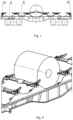
- Fig. 2 - view of the device blocking the movement of sheet metal coils
- Fig. 3 blocking device load
- Fig. 3 screw drive mechanism
- Fig. 5 block diagram of the control system.
- the load blocking system on freight wagons with at least one trough is equipped with blocking arms 1, which limit the lateral movement of the load in the form of coils.
- four locking arms 1 are used for one trough.
- the locking arms 1 are mounted movably on the guide pipes 2 located parallel to the trough 6 on the upper edge of the trough 6 or between the neighboring troughs 6.
- the nuts 7 are mechanically connected to the locking arms 1.
- the inner end 3' of each propeller 3 is connected by a claw coupling 5 with the electric motor 4.
- the electric motors 4 rotate the propellers 3, which causes the nuts to move along the propellers 3 and moving the locking arms 1 towards or away from the load.
- the propeller 3 and nuts 7 have a self-locking thread, therefore the locking arms 1 cannot move on their own and, when pushed close to the load, they protect it against transverse movement.
- the electric motors 4 are controlled by an electronic control system, which consists of ultrasonic sensors (9), local control units (10), a central control unit (11) and control panels (12) preferably located at the ends of the car on both sides on the walls side boxes.
- an electronic control system which consists of ultrasonic sensors (9), local control units (10), a central control unit (11) and control panels (12) preferably located at the ends of the car on both sides on the walls side boxes.
- Electric motors 4 assigned to a single trough 6 are controlled by a local control unit 10 coupled with at least one ultrasonic sensor 9 for each trough, which detects the load in the trough 6.
- the central control unit 11 is responsible for the sequential process of moving the locking arms 1 in the troughs, protecting the electrical power system against excessive overload.
- the sequential process of moving the locking arms 1 in or out consists in the fact that the arms are not moved in or out simultaneously in all troughs, but one at a time in each trough 6.
- the electric motors 4 and the electronic control system are supplied with electricity from the electric battery 13 mounted on the car, which is charged by the generator 14 mounted in the axle box of the wheelset and the charging regulator 15.
- Ultrasonic sensors 9 placed in the center of each trough 6 detect the load in the trough 6 and allow the locking arms 1 to be automatically moved to contact with the load or to a predetermined distance from the load specified by the device operator.
- the locking device can be operated via the panels 12 or remotely via the Bluetooth wireless standard.
- the opposite 3" end of the propeller 3, led outside the device, has a shaped tip 8, on which a crank, a handwheel or a portable electric device can be placed, which in the event of failure of the electric drive can move the locking arms 1 in an emergency.
Landscapes
- Engineering & Computer Science (AREA)
- Transportation (AREA)
- Mechanical Engineering (AREA)
- Warehouses Or Storage Devices (AREA)
- Forklifts And Lifting Vehicles (AREA)
Abstract
Description
- The subject of the invention is a system for locking loads, especially on railway wagons, intended in particular for locking coil-shaped loads.
- Technical solutions known to be in use for locking devices in the direction transverse to the direction of travel of the load, such as, for example, metal coils or concrete coils on railway wagons, have locking arms that can move and rotate along the guide pipe. The arms are usually moved and locked manually, requiring the person to climb the wagons loading area. There are also known solutions that allow the arms to be moved and locked from the track level. Each locking arm is moved and locked individually. For this reason, load securing must be carried out by two persons, or one person must operate the wagon from both sides.
- The Polish patent
PL222981 (B1 - From the Slovak description of the utility model No.
6092 - The essence of the invention consists in the fact that the load blocking system, especially on freight wagons equipped with troughs, consists of:
- a set of sliding locking arms mounted on the guide tubes and propellers parallel to the guide tubes cooperating with the nuts, each propeller being equipped with an electric motor connected to its end by means of a dog clutch,
- electronic control system with ultrasonic sensors,
- independent power supply system.
- In a preferred embodiment, the electric motors are stepper motors.
- Preferably, the electric motors are integrated with a common independent power supply system.
- Preferably, the electric motors assigned to a single trough are connected to a local control unit coupled to at least one ultrasonic sensor for each trough that detects the load in the trough. Preferably, the ultrasonic sensor is located in the middle of the wagon trough. Advantageously, the electronic control system, in addition to ultrasonic sensors, consists of local control units, control panels and a central control unit responsible for sequential advancing and retracting the locking arms in successive troughs.
- Preferably, the independent power supply system consists of a generator, a battery and a charge controller.
- Most preferably, the generator is mounted in the axle box of the wagon wheelset.
- In a preferred embodiment, the propellers and the cooperating nuts mechanically connected to the locking arms are equipped with a self-locking thread.
- Preferably, the opposite end of the propeller is equipped with a shaped tip for connecting the emergency drive.
- The main advantage of the device according to the invention is the stepless system of moving the locking arms together with the electronic control system, which makes it possible to block the load placed anywhere in the trough.
- The device enables automatic moving of the locking arms to contact with the load or to a predetermined distance from the load specified by the device operator. Ultrasonic sensors assigned to each trough detect the load and ensure maintenance-free operation of the system. The control desks used by the staff to control the operation of the device can be mounted anywhere in the car, preferably at the ends of the car on both sides. The locking device can also be operated remotely via the Bluetooth wireless standard. The device is powered from an independent power supply system.
- The subject of the invention is illustrated by the embodiment shown in the drawing, in which
Fig. 1 shows a view of a freight car with devices blocking the movement of sheet metal coils in the transverse direction of the wagon,Fig. 2 - view of the device blocking the movement of sheet metal coils,Fig. 3 - blocking device load,Fig. 3 - screw drive mechanism andFig. 5 - block diagram of the control system. - The load blocking system on freight wagons with at least one trough is equipped with blocking
arms 1, which limit the lateral movement of the load in the form of coils. As a standard, four lockingarms 1 are used for one trough. The lockingarms 1 are mounted movably on theguide pipes 2 located parallel to thetrough 6 on the upper edge of thetrough 6 or between the neighboringtroughs 6. Parallel to theguide pipes 2, there are drivescrews 3 with which thenuts 7 work together. Thenuts 7 are mechanically connected to the lockingarms 1. The inner end 3' of eachpropeller 3 is connected by aclaw coupling 5 with theelectric motor 4. Theelectric motors 4 rotate thepropellers 3, which causes the nuts to move along thepropellers 3 and moving the lockingarms 1 towards or away from the load. Thepropeller 3 andnuts 7 have a self-locking thread, therefore the lockingarms 1 cannot move on their own and, when pushed close to the load, they protect it against transverse movement. - The
electric motors 4 are controlled by an electronic control system, which consists of ultrasonic sensors (9), local control units (10), a central control unit (11) and control panels (12) preferably located at the ends of the car on both sides on the walls side boxes. -
Electric motors 4 assigned to asingle trough 6 are controlled by alocal control unit 10 coupled with at least oneultrasonic sensor 9 for each trough, which detects the load in thetrough 6. Thecentral control unit 11 is responsible for the sequential process of moving the lockingarms 1 in the troughs, protecting the electrical power system against excessive overload. The sequential process of moving the lockingarms 1 in or out consists in the fact that the arms are not moved in or out simultaneously in all troughs, but one at a time in eachtrough 6. - The
electric motors 4 and the electronic control system are supplied with electricity from theelectric battery 13 mounted on the car, which is charged by thegenerator 14 mounted in the axle box of the wheelset and thecharging regulator 15.Ultrasonic sensors 9 placed in the center of eachtrough 6 detect the load in thetrough 6 and allow thelocking arms 1 to be automatically moved to contact with the load or to a predetermined distance from the load specified by the device operator. The locking device can be operated via thepanels 12 or remotely via the Bluetooth wireless standard. - The opposite 3" end of the
propeller 3, led outside the device, has ashaped tip 8, on which a crank, a handwheel or a portable electric device can be placed, which in the event of failure of the electric drive can move the lockingarms 1 in an emergency.
Claims (10)
- A load locking system, especially on freight wagons equipped with troughs (6), characterized in that it consists of:- a set of sliding locking arms (1) mounted on guide pipes (2) and parallel to the guide pipes (2) of the drive screws (3) cooperating with the nuts (7), each screw (3) being equipped with a motor (4) electric connected to its end (3') by means of a claw coupling (5),- electronic control system with ultrasonic sensors (9),- independent power supply system.
- A system according to claim 1, characterized in that the electric motors (4) are stepper motors.
- A system according to claim 1 or 2, characterized in that the electric motors (4) are integrated with a common independent power supply system.
- A system according to claim 1 or 2 or 3, characterized in that the electric motors (4) assigned to a single trough (6) are connected to a local control unit (10) coupled with at least one ultrasonic sensor (9) for each trough (6) detecting the load in troughs (6).
- A system according to claim 4, characterized in that the ultrasonic sensor is located in the central part of the trough (6) of the wagon.
- A system according to claim 1 or 2 or 3 or 4, characterized in that the electronic control system, apart from ultrasonic sensors (9), consists of local control units (10), control panels (12) and a central control unit (11) responsible for sequential advancing and retracting the arms (1) blockers in successive moguls (6).
- A system according to claim 1 or 2 or 3 or 4 or 6, characterized in that the independent power supply system consists of a generator (14), a battery (13) and a charge regulator (15).
- A system according to claim 1 or 7, characterized in that the generator (14) is mounted in the axle box of the wagon wheelset.
- A system according to claim 1, characterized in that the drive screws (3) and the nuts (7) cooperating with them, mechanically connected to the locking arms (1), are equipped with a self-locking thread.
- A system according to claim 1, characterized in that the opposite end (3") of the propeller (3) is equipped with a shaped tip (8) for connecting the emergency drive.
Priority Applications (1)
| Application Number | Priority Date | Filing Date | Title |
|---|---|---|---|
| HRP20260112TT HRP20260112T1 (en) | 2021-07-29 | 2022-07-27 | Load locking system, especially on freight wagons |
Applications Claiming Priority (1)
| Application Number | Priority Date | Filing Date | Title |
|---|---|---|---|
| PL438629A PL243846B1 (en) | 2021-07-29 | 2021-07-29 | Load locking system, especially on freight wagons |
Publications (2)
| Publication Number | Publication Date |
|---|---|
| EP4190665A1 true EP4190665A1 (en) | 2023-06-07 |
| EP4190665B1 EP4190665B1 (en) | 2025-10-29 |
Family
ID=80492688
Family Applications (1)
| Application Number | Title | Priority Date | Filing Date |
|---|---|---|---|
| EP22187355.7A Active EP4190665B1 (en) | 2021-07-29 | 2022-07-27 | Load locking system, especially on freight wagons |
Country Status (3)
| Country | Link |
|---|---|
| EP (1) | EP4190665B1 (en) |
| HR (1) | HRP20260112T1 (en) |
| PL (1) | PL243846B1 (en) |
Citations (3)
| Publication number | Priority date | Publication date | Assignee | Title |
|---|---|---|---|---|
| EP0712771B1 (en) * | 1994-11-15 | 1999-06-16 | Societe Nationale Des Chemins De Fer Francais | Device for automatically securing cylindrical pieces and railway wagon utilizing such a device |
| DE202015005518U1 (en) * | 2015-08-05 | 2016-01-08 | Karl-Friedrich Bremer | Drive for a fixing device for cylindrical transport goods on vehicles |
| PL222981B1 (en) | 2012-07-16 | 2016-09-30 | Wagony Świdnica Spółka Akcyjna | Locking device for a load on freight wagons |
-
2021
- 2021-07-29 PL PL438629A patent/PL243846B1/en unknown
-
2022
- 2022-07-27 EP EP22187355.7A patent/EP4190665B1/en active Active
- 2022-07-27 HR HRP20260112TT patent/HRP20260112T1/en unknown
Patent Citations (3)
| Publication number | Priority date | Publication date | Assignee | Title |
|---|---|---|---|---|
| EP0712771B1 (en) * | 1994-11-15 | 1999-06-16 | Societe Nationale Des Chemins De Fer Francais | Device for automatically securing cylindrical pieces and railway wagon utilizing such a device |
| PL222981B1 (en) | 2012-07-16 | 2016-09-30 | Wagony Świdnica Spółka Akcyjna | Locking device for a load on freight wagons |
| DE202015005518U1 (en) * | 2015-08-05 | 2016-01-08 | Karl-Friedrich Bremer | Drive for a fixing device for cylindrical transport goods on vehicles |
Also Published As
| Publication number | Publication date |
|---|---|
| PL438629A1 (en) | 2022-02-28 |
| EP4190665B1 (en) | 2025-10-29 |
| HRP20260112T1 (en) | 2026-05-22 |
| PL243846B1 (en) | 2023-10-23 |
Similar Documents
| Publication | Publication Date | Title |
|---|---|---|
| US7900562B2 (en) | Split rail trolley system | |
| CN206307626U (en) | Wireless shuttle battery swap trolley | |
| JP3179460B2 (en) | Work transfer device | |
| CN113479769B (en) | A two-way anti-slip device for monorail crane based on internal ratchet mechanism | |
| CN113650521B (en) | Battery replacing device and battery replacing station | |
| ES2934472T3 (en) | Conveyor device, processing facility, method for transporting and/or processing objects | |
| CN113525209A (en) | Multifunctional electric power maintenance vehicle | |
| CN106176147A (en) | Rail safety transducer | |
| CN109436657A (en) | It is capable of the workpiece waggon of auto-steering and lifting | |
| EP4190665B1 (en) | Load locking system, especially on freight wagons | |
| CN112320535A (en) | Safe car device for elevator | |
| JP5574426B2 (en) | Self-propelled bogie mobile | |
| CN107605212B (en) | The automatic intelligent three-dimensional garage for stopping taking | |
| SE455088B (en) | DEVICE MOVING DEVICE, LIKE A CONTAINER | |
| CN216915582U (en) | Electric locomotive maintenance station | |
| US3038614A (en) | Missile cart | |
| CN112849198A (en) | Combined wheel type equipment railway transportation reinforcing device | |
| CN2241734Y (en) | Special-purpose equipment conveying car in stereo automatic carport | |
| CN105735695A (en) | Rotary parking garage | |
| CN110589414A (en) | H-Frame automated wire feeding system for component transport | |
| CN214456561U (en) | AGV for assembling vehicle engine | |
| CN109850148A (en) | A kind of automation unmanned plane express delivery delivery system | |
| CN206886545U (en) | Navigate car and its driving separator | |
| RU2337219C1 (en) | Device for cars transportation | |
| CN207780587U (en) | Trolley automatic control system |
Legal Events
| Date | Code | Title | Description |
|---|---|---|---|
| REG | Reference to a national code |
Ref country code: HR Ref legal event code: TUEP Ref document number: P20260112T Country of ref document: HR |
|
| PUAI | Public reference made under article 153(3) epc to a published international application that has entered the european phase |
Free format text: ORIGINAL CODE: 0009012 |
|
| STAA | Information on the status of an ep patent application or granted ep patent |
Free format text: STATUS: THE APPLICATION HAS BEEN PUBLISHED |
|
| AK | Designated contracting states |
Kind code of ref document: A1 Designated state(s): AL AT BE BG CH CY CZ DE DK EE ES FI FR GB GR HR HU IE IS IT LI LT LU LV MC MK MT NL NO PL PT RO RS SE SI SK SM TR |
|
| STAA | Information on the status of an ep patent application or granted ep patent |
Free format text: STATUS: REQUEST FOR EXAMINATION WAS MADE |
|
| 17P | Request for examination filed |
Effective date: 20240305 |
|
| RBV | Designated contracting states (corrected) |
Designated state(s): AL AT BE BG CH CY CZ DE DK EE ES FI FR GB GR HR HU IE IS IT LI LT LU LV MC MK MT NL NO PL PT RO RS SE SI SK SM TR |
|
| RIN1 | Information on inventor provided before grant (corrected) |
Inventor name: KAKOWCZYK, WIESLAW Inventor name: SZMIDT, TOMASZ Inventor name: STUDZINSKI, DIONIZY Inventor name: DRASZKIEWICZ, WOJCIECH Inventor name: KONSTANTY, PIOTR Inventor name: PAZDZIERNIAK, PRZEMYSLAW |
|
| GRAP | Despatch of communication of intention to grant a patent |
Free format text: ORIGINAL CODE: EPIDOSNIGR1 |
|
| STAA | Information on the status of an ep patent application or granted ep patent |
Free format text: STATUS: GRANT OF PATENT IS INTENDED |
|
| INTG | Intention to grant announced |
Effective date: 20250228 |
|
| RIN1 | Information on inventor provided before grant (corrected) |
Inventor name: KAKOWCZYK, WIESLAW Inventor name: SZMIDT, TOMASZ Inventor name: STUDZINSKI, DIONIZY Inventor name: DRASZKIEWICZ, WOJCIECH Inventor name: KONSTANTY, PIOTR Inventor name: PAZDZIERNIAK, PRZEMYSLAW |
|
| GRAS | Grant fee paid |
Free format text: ORIGINAL CODE: EPIDOSNIGR3 |
|
| GRAA | (expected) grant |
Free format text: ORIGINAL CODE: 0009210 |
|
| STAA | Information on the status of an ep patent application or granted ep patent |
Free format text: STATUS: THE PATENT HAS BEEN GRANTED |
|
| RAP3 | Party data changed (applicant data changed or rights of an application transferred) |
Owner name: GREENBRIER POLAND SP. Z O.O. |
|
| AK | Designated contracting states |
Kind code of ref document: B1 Designated state(s): AL AT BE BG CH CY CZ DE DK EE ES FI FR GB GR HR HU IE IS IT LI LT LU LV MC MK MT NL NO PL PT RO RS SE SI SK SM TR |
|
| REG | Reference to a national code |
Ref country code: CH Ref legal event code: F10 Free format text: ST27 STATUS EVENT CODE: U-0-0-F10-F00 (AS PROVIDED BY THE NATIONAL OFFICE) Effective date: 20251029 Ref country code: GB Ref legal event code: FG4D |
|
| REG | Reference to a national code |
Ref country code: IE Ref legal event code: FG4D |
|
| REG | Reference to a national code |
Ref country code: DE Ref legal event code: R096 Ref document number: 602022023793 Country of ref document: DE |
|
| REG | Reference to a national code |
Ref country code: NL Ref legal event code: MP Effective date: 20251029 |
|
| PG25 | Lapsed in a contracting state [announced via postgrant information from national office to epo] |
Ref country code: ES Free format text: LAPSE BECAUSE OF FAILURE TO SUBMIT A TRANSLATION OF THE DESCRIPTION OR TO PAY THE FEE WITHIN THE PRESCRIBED TIME-LIMIT Effective date: 20251029 |
|
| REG | Reference to a national code |
Ref country code: LT Ref legal event code: MG9D |
|
| PG25 | Lapsed in a contracting state [announced via postgrant information from national office to epo] |
Ref country code: NO Free format text: LAPSE BECAUSE OF FAILURE TO SUBMIT A TRANSLATION OF THE DESCRIPTION OR TO PAY THE FEE WITHIN THE PRESCRIBED TIME-LIMIT Effective date: 20260129 |
|
| PG25 | Lapsed in a contracting state [announced via postgrant information from national office to epo] |
Ref country code: FI Free format text: LAPSE BECAUSE OF FAILURE TO SUBMIT A TRANSLATION OF THE DESCRIPTION OR TO PAY THE FEE WITHIN THE PRESCRIBED TIME-LIMIT Effective date: 20251029 Ref country code: AT Free format text: LAPSE BECAUSE OF FAILURE TO SUBMIT A TRANSLATION OF THE DESCRIPTION OR TO PAY THE FEE WITHIN THE PRESCRIBED TIME-LIMIT Effective date: 20251029 |
|
| REG | Reference to a national code |
Ref country code: AT Ref legal event code: MK05 Ref document number: 1851261 Country of ref document: AT Kind code of ref document: T Effective date: 20251029 |
|
| PG25 | Lapsed in a contracting state [announced via postgrant information from national office to epo] |
Ref country code: NL Free format text: LAPSE BECAUSE OF FAILURE TO SUBMIT A TRANSLATION OF THE DESCRIPTION OR TO PAY THE FEE WITHIN THE PRESCRIBED TIME-LIMIT Effective date: 20251029 |
|
| PG25 | Lapsed in a contracting state [announced via postgrant information from national office to epo] |
Ref country code: RS Free format text: LAPSE BECAUSE OF FAILURE TO SUBMIT A TRANSLATION OF THE DESCRIPTION OR TO PAY THE FEE WITHIN THE PRESCRIBED TIME-LIMIT Effective date: 20260129 |
|
| PG25 | Lapsed in a contracting state [announced via postgrant information from national office to epo] |
Ref country code: IS Free format text: LAPSE BECAUSE OF FAILURE TO SUBMIT A TRANSLATION OF THE DESCRIPTION OR TO PAY THE FEE WITHIN THE PRESCRIBED TIME-LIMIT Effective date: 20260228 |
|
| PG25 | Lapsed in a contracting state [announced via postgrant information from national office to epo] |
Ref country code: PT Free format text: LAPSE BECAUSE OF FAILURE TO SUBMIT A TRANSLATION OF THE DESCRIPTION OR TO PAY THE FEE WITHIN THE PRESCRIBED TIME-LIMIT Effective date: 20260302 |
|
| PG25 | Lapsed in a contracting state [announced via postgrant information from national office to epo] |
Ref country code: PL Free format text: LAPSE BECAUSE OF FAILURE TO SUBMIT A TRANSLATION OF THE DESCRIPTION OR TO PAY THE FEE WITHIN THE PRESCRIBED TIME-LIMIT Effective date: 20251029 |
|
| PG25 | Lapsed in a contracting state [announced via postgrant information from national office to epo] |
Ref country code: LV Free format text: LAPSE BECAUSE OF FAILURE TO SUBMIT A TRANSLATION OF THE DESCRIPTION OR TO PAY THE FEE WITHIN THE PRESCRIBED TIME-LIMIT Effective date: 20251029 |
|
| REG | Reference to a national code |
Ref country code: SK Ref legal event code: T3 Ref document number: E 48277 Country of ref document: SK |
|
| REG | Reference to a national code |
Ref country code: HR Ref legal event code: T1PR Ref document number: P20260112 Country of ref document: HR |
|
| PG25 | Lapsed in a contracting state [announced via postgrant information from national office to epo] |
Ref country code: LT Free format text: LAPSE BECAUSE OF FAILURE TO SUBMIT A TRANSLATION OF THE DESCRIPTION OR TO PAY THE FEE WITHIN THE PRESCRIBED TIME-LIMIT Effective date: 20251029 |
|
| PG25 | Lapsed in a contracting state [announced via postgrant information from national office to epo] |
Ref country code: SM Free format text: LAPSE BECAUSE OF FAILURE TO SUBMIT A TRANSLATION OF THE DESCRIPTION OR TO PAY THE FEE WITHIN THE PRESCRIBED TIME-LIMIT Effective date: 20251029 |
|
| PG25 | Lapsed in a contracting state [announced via postgrant information from national office to epo] |
Ref country code: DK Free format text: LAPSE BECAUSE OF FAILURE TO SUBMIT A TRANSLATION OF THE DESCRIPTION OR TO PAY THE FEE WITHIN THE PRESCRIBED TIME-LIMIT Effective date: 20251029 |
|
| PG25 | Lapsed in a contracting state [announced via postgrant information from national office to epo] |
Ref country code: IT Free format text: LAPSE BECAUSE OF FAILURE TO SUBMIT A TRANSLATION OF THE DESCRIPTION OR TO PAY THE FEE WITHIN THE PRESCRIBED TIME-LIMIT Effective date: 20251029 |
|
| PG25 | Lapsed in a contracting state [announced via postgrant information from national office to epo] |
Ref country code: EE Free format text: LAPSE BECAUSE OF FAILURE TO SUBMIT A TRANSLATION OF THE DESCRIPTION OR TO PAY THE FEE WITHIN THE PRESCRIBED TIME-LIMIT Effective date: 20251029 |
|
| PG25 | Lapsed in a contracting state [announced via postgrant information from national office to epo] |
Ref country code: SE Free format text: LAPSE BECAUSE OF FAILURE TO SUBMIT A TRANSLATION OF THE DESCRIPTION OR TO PAY THE FEE WITHIN THE PRESCRIBED TIME-LIMIT Effective date: 20251029 |