EP4190580A1 - Printing device - Google Patents
Printing device Download PDFInfo
- Publication number
- EP4190580A1 EP4190580A1 EP21851117.8A EP21851117A EP4190580A1 EP 4190580 A1 EP4190580 A1 EP 4190580A1 EP 21851117 A EP21851117 A EP 21851117A EP 4190580 A1 EP4190580 A1 EP 4190580A1
- Authority
- EP
- European Patent Office
- Prior art keywords
- shaft
- guide
- printing device
- cassette
- head support
- Prior art date
- Legal status (The legal status is an assumption and is not a legal conclusion. Google has not performed a legal analysis and makes no representation as to the accuracy of the status listed.)
- Granted
Links
Images







Classifications
-
- B—PERFORMING OPERATIONS; TRANSPORTING
- B41—PRINTING; LINING MACHINES; TYPEWRITERS; STAMPS
- B41J—TYPEWRITERS; SELECTIVE PRINTING MECHANISMS, i.e. MECHANISMS PRINTING OTHERWISE THAN FROM A FORME; CORRECTION OF TYPOGRAPHICAL ERRORS
- B41J2/00—Typewriters or selective printing mechanisms characterised by the printing or marking process for which they are designed
- B41J2/315—Typewriters or selective printing mechanisms characterised by the printing or marking process for which they are designed characterised by selective application of heat to a heat sensitive printing or impression-transfer material
- B41J2/32—Typewriters or selective printing mechanisms characterised by the printing or marking process for which they are designed characterised by selective application of heat to a heat sensitive printing or impression-transfer material using thermal heads
- B41J2/325—Typewriters or selective printing mechanisms characterised by the printing or marking process for which they are designed characterised by selective application of heat to a heat sensitive printing or impression-transfer material using thermal heads by selective transfer of ink from ink carrier, e.g. from ink ribbon or sheet
-
- B—PERFORMING OPERATIONS; TRANSPORTING
- B41—PRINTING; LINING MACHINES; TYPEWRITERS; STAMPS
- B41J—TYPEWRITERS; SELECTIVE PRINTING MECHANISMS, i.e. MECHANISMS PRINTING OTHERWISE THAN FROM A FORME; CORRECTION OF TYPOGRAPHICAL ERRORS
- B41J17/00—Mechanisms for manipulating page-width impression-transfer material, e.g. carbon paper
- B41J17/32—Detachable carriers or holders for impression-transfer material mechanism
-
- B—PERFORMING OPERATIONS; TRANSPORTING
- B41—PRINTING; LINING MACHINES; TYPEWRITERS; STAMPS
- B41J—TYPEWRITERS; SELECTIVE PRINTING MECHANISMS, i.e. MECHANISMS PRINTING OTHERWISE THAN FROM A FORME; CORRECTION OF TYPOGRAPHICAL ERRORS
- B41J35/00—Other apparatus or arrangements associated with, or incorporated in, ink-ribbon mechanisms
- B41J35/28—Detachable carriers or holders for ink-ribbon mechanisms
-
- B—PERFORMING OPERATIONS; TRANSPORTING
- B41—PRINTING; LINING MACHINES; TYPEWRITERS; STAMPS
- B41J—TYPEWRITERS; SELECTIVE PRINTING MECHANISMS, i.e. MECHANISMS PRINTING OTHERWISE THAN FROM A FORME; CORRECTION OF TYPOGRAPHICAL ERRORS
- B41J2202/00—Embodiments of or processes related to ink-jet or thermal heads
- B41J2202/30—Embodiments of or processes related to thermal heads
- B41J2202/31—Thermal printer with head or platen movable
Definitions
- the present invention relates to a printing device.
- Patent Literature 1 discloses a thermal transfer type printing device in which a ribbon cassette supporting an ink ribbon is attached to and detached from a printing device main body.
- Two locating guide shafts and a slider operation unit are provided on a cassette base of the ribbon cassette.
- the two locating guide shafts are provided at both left and right ends of the cassette base, and extend parallel to an attachment and detachment direction of the ribbon cassette.
- the slider operation unit is provided to be movable in a left-right direction.
- an interlocking bar is provided to be movable in the left-right direction in conjunction with the slider operation unit, and locking claws are respectively provided at both left and right end portions of the interlocking bar.
- the two locating guide shafts are respectively inserted and fitted into two positioning guide holes provided in the printing device main body.
- the two locking claws move in the left-right direction in conjunction with the slider operation unit via the interlocking bar by an operation of the slider operation unit, so that the two locking claws are respectively locked to two locked portions provided on a printing device main body side, and a mounted state is locked.
- Patent Literature 1 JP2018-202630A
- An object of the present invention is to provide a printing device in which a wide space in the device can be used.
- a printing device of claim 1 includes: a main body having a head support surface on which a thermal head is supported; and a cassette including a plate-shaped cassette base, a supply roll shaft, and a winding roll shaft, and detachably attached to the head support surface of the main body along an axis direction of the supply roll shaft and the winding roll shaft, the supply roll shaft rotatably supporting a ribbon supply roll and being provided on one side, in a predetermined direction, of a facing surface of the cassette base facing the head support surface, and the winding roll shaft rotatably supporting a ribbon winding roll and being provided on an other side, in the predetermined direction, of the facing surface, in which the printing device is configured to perform printing by transferring ink of an ink ribbon onto a print medium due to heating of the thermal head, and the ink ribbon is fed out from the ribbon supply roll and wound around the ribbon winding roll through the thermal head, and in which the printing device further includes: a guided portion provided on the facing surface of the cassette base; a guide portion provided at
- the guide portion and the lock unit can be provided at the same position. Therefore, the printing device can effectively use a limited space in the printing device as compared with a configuration in which the guide portion and the lock unit are provided at different positions. Since the guided portion can be locked to the guide portion in the state where the guided portion is guided and located to the predetermined position by the guide portion, guiding and locking operations of the guided portion can be performed by a series of actions. As a result, the printing device can improve usability.
- the "predetermined position” means a predetermined position of the guided portion with respect to the guide portion in a state where the cassette is normally mounted to the main body in an attachment and detachment direction of the cassette.
- the guided portion of the printing device of claim 2 may be provided between the supply roll shaft and the winding roll shaft in the predetermined direction on the facing surface of the cassette base, and may be provided, in a state where the cassette is mounted, at a location on a side opposite to the thermal head with respect to the supply roll shaft in an orthogonal direction that is orthogonal to the predetermined direction and the axis direction. Therefore, the cassette base is supported in a balanced manner in the predetermined direction with respect to the head support surface of the main body.
- a space between the supply roll shaft and the winding roll shaft is limited by a thickness of each of the ribbon supply roll and the ribbon winding roll, but the limited space in the printing device can be more effectively used by providing the guided portion in a dead space on the side opposite to the thermal head with respect to the supply roll shaft in the orthogonal direction.
- the printing device of claim 3 may further include a grip portion provided on an outer surface of the cassette base on a side opposite to the facing surface, and configured to be gripped by a user, and the release unit may be provided in the grip portion.
- the release unit since the release unit is provided in the grip portion, the user can perform a release operation while gripping the grip portion. As a result, the aspect can provide the printing device having high usability.
- the guided portion of the printing device of claim 4 may include a rod-shaped shaft extending from the facing surface toward a side of the head support surface in parallel with the axis direction
- the guide portion may include a cylindrical guide body extending from the head support surface toward a side of the facing surface in parallel with the axis direction, and configured to guide and locate the shaft to the predetermined position by inserting the shaft inside the cylindrical guide body
- the lock unit may include: an engagement portion provided to be cable of protruding from an opening portion from an inner side toward an outer side of the shaft in a radial direction, and being engageable with an engaged hole through the opening portion in a state where the shaft is guided to the predetermined position by the cylindrical guide body, the opening portion being provided on an outer peripheral surface of the shaft, and the engaged hole is provided in an outer peripheral surface of the cylindrical guide body
- the release unit may be provided in the shaft, and may be configured to move the engagement portion to the inner side in the radial direction to disengage the engagement portion from the engaged hole.
- the shaft is automatically guided to the predetermined position by inserting the shaft into the cylindrical guide body.
- the engagement portion engages with the engaged hole in a state where the shaft is guided to the predetermined position, so that the shaft is locked to the cylindrical guide body. Guiding and locking can be simultaneously performed by one action of inserting the shaft into the cylindrical guide body, so that operability is improved.
- the locking can be easily released by disengaging the engagement portion from the engaged hole.
- the shaft of the printing device of claim 5 may include: a cylindrical holder fixed to the facing surface and extending in parallel with the axis direction toward the side of the head support surface; and a cylindrical guide shaft coaxially disposed in the holder and extending from a tip end portion of the holder toward the side of the head support surface, the tip end portion facing the side of the head support surface,
- the release unit may include: a rod-shaped center shaft disposed in the holder and the guide shaft and provided to be movable along a length direction of the holder and the guide shaft
- the lock unit may include: a first biasing member configured to constantly bias the center shaft toward a side of the cassette base
- the engagement portion may be a spherical body, and may be provided between the guide shaft and the center shaft, the spherical body being disposed to be slidable on an outer peripheral surface of the center shaft, and a part of the spherical body being exposed from the opening portion to engage with the engaged hole in a first state where the s
- the center shaft by moving the center shaft within the guide shaft and causing the center shaft to be the first state, a part of the spherical body can be exposed from the opening portion and can engage with the engaged hole, and the shaft can be locked to the cylindrical guide body.
- the spherical body moves inward from the opening portion to be disengaged from the engaged hole, so that the locking can be easily released.
- the guide shaft of the printing device of claim 6 may be supported in the holder to be rotatable about an axis, and the printing device may include: a second biasing member provided in the holder and configured to constantly bias the guide shaft in one direction about the axis; and a guide groove provided on the outer peripheral surface of the cylindrical guide body, extending from one end portion of the cylindrical guide body toward the engaged hole to be inclined in a direction opposite to the one direction about the axis, and configured to guide the part of the spherical body exposed from the opening portion from the one end portion to the engaged hole, the one end portion facing the side of the cassette base.
- the shaft is inserted along an inside of the cylindrical guide body, and a part of the spherical body exposed from the opening portion of the shaft is pushed toward the side of the head support surface along the guide groove.
- the guide shaft rotates in the same direction together with the spherical body.
- the guide shaft is biased in the one direction about the axis and pulled back by the second biasing member, and the spherical body engages with the engaged hole to perform the locking.
- the guiding and the locking can be performed by only one action of inserting the shaft into the cylindrical guide body.
- the second biasing member of the printing device of claim 7 may be a torsion coil spring. As a result, a biasing force can be easily applied to the guide shaft in the one direction about the axis.
- the release unit of the printing device of claim 8 may include an operation unit fixed to one end portion of the center shaft located on a side of the holder, and configured to push the center shaft toward the side of the head support surface. Since the user can release the locking only by pushing the operation unit toward the side of the head support surface, the release operation can be performed more easily. Therefore, the printing device can improve the usability.
- the shaft of the printing device of claim 9 may include: a cylindrical holder fixed to the facing surface and extending in parallel with the axis direction toward the side of the head support surface; and a cylindrical guide shaft coaxially disposed in the holder and extending from a tip end portion of the holder toward the side of the head support surface, the tip end portion facing the side of the head support surface
- the release unit may include: a rod-shaped first shaft and a rod-shaped second shaft disposed in the holder and the guide shaft, and coaxially provided to be movable along a length direction of the holder and the guide shaft
- the cylindrical guide body may include an abutment portion configured to, in a state where the cassette is mounted to the main body, abut against the second shaft to restrict the guide shaft from moving toward the side of the head support surface in the length direction of the guide shaft
- the lock unit may include: a third biasing member disposed between the first shaft and the second shaft, and configured to bias the first shaft toward a side of the cassette base in a state where
- the printing device by moving the first shaft within the guide shaft and causing the first shaft to be the locked state, a part of the spherical body can be exposed from the opening portion and can engage with the engaged hole, and the shaft can be locked to the cylindrical guide body.
- the spherical body moves inward from the opening portion to be disengaged from the engaged hole, so that the locking can be easily released.
- a printing device 1 shown in FIG. 1 can print desired characters and graphics by allowing a belt-shaped packaging material (not shown) fed out from a packaging material supply roll (not shown) to pass through a lower portion from left to right.
- the printing device 1 is formed in a substantially rectangular parallelepiped shape, and includes an outer decorative plate 2.
- the outer decorative plate 2 covers an outer peripheral surface of the printing device 1 around an axis in a front-rear direction, and can be attached to and detached from the printing device 1.
- the outer decorative plate 2 is not shown.
- the printing device 1 includes a main body 3 and a cassette 4 which are separable from each other in the front-rear direction.
- the outer decorative plate 2 can be mounted on a side of the main body 3, and the cassette 4 is inserted inside the outer decorative plate 2. As shown in FIG.
- the cassette 4 can be attached to and detached from the main body 3 by being inserted and pulled out along an axis direction (front-rear direction) of a supply roll shaft 43 and a winding roll shaft 44 which are provided on a side of the cassette 4 and which will be described later.
- the cassette 4 is disposed on a front side of the printing device 1, and includes a cassette base 41, a handle 42, the supply roll shaft 43, the winding roll shaft 44, two guide rollers 45 and 46, a locating shaft 50, and the like.
- the cassette base 41 is formed in a substantially rectangular shape in a front view.
- the handle 42 is provided on a side of a front surface 41A of the cassette base 41, and includes a grip portion 421, an upper support portion 422, and a lower support portion 423.
- the grip portion 421 is provided at a position spaced forward from a front surface 41A to extend in an up-down direction, and is gripped by a user.
- the upper support portion 422 bridges between a central portion of an upper end portion of the cassette base 41 and an upper end portion of the grip portion 421.
- the lower support portion 423 bridges between a central portion of a lower end portion of the cassette base 41 and a lower end portion of the grip portion 421.
- the handle 42 is provided to bridge, in the up-down direction, between the respective central portions of the upper end portion and the lower end portion of the cassette base 41.
- the handle 42 is gripped by the user when the cassette 4 is to be attached to and detached from the main body 3.
- a release button 56 is provided in an upper portion of a front surface of the grip portion 421. The release button 56 is pressed down from a front by the user in order to release locking to the main body 3 by the locating shaft 50 to be described later.
- the supply roll shaft 43 and the winding roll shaft 44 are provided side by side in a left-right direction on a back surface 41B of the cassette base 41 and above a central position in the up-down direction.
- the supply roll shaft 43 is disposed on a left side
- the winding roll shaft 44 is disposed on a right side.
- the supply roll shaft 43 and the winding roll shaft 44 are provided to extend rearward from the back surface 41B, and are each provided to be rotatable about a central axis.
- One end of a series of belt-shaped ink ribbons (not shown) is fixed to the supply roll shaft 43 in advance and the ink ribbons are wound around the supply roll shaft 43 in advance.
- the other end of the ink ribbons is fixed to the winding roll shaft 44, so that the ink ribbons fed out from the supply roll shaft 43 are wound into a roll shape.
- the guide roller 45 is provided at a lower left corner portion of the back surface 41B.
- the guide roller 46 is provided at a lower right corner portion of the back surface 41B.
- the guide rollers 45 and 46 are provided to extend rearward from the back surface 41B, and are each provided to be rotatable about a central axis.
- the ink ribbons fed out from the supply roll shaft 43 are finally guided to the winding roll shaft 44 through a conveyance path that is bent by abutting against outer peripheral surfaces of the two guide rollers 45 and 46.
- the locating shaft 50 is provided in a central upper portion, between the supply roll shaft 43 and the winding roll shaft 44, of the back surface 41B.
- the position is in a (central in an example) region between the supply roll shaft 43 and the winding roll shaft 44 in the left-right direction, and is located substantially at an upper end of the cassette base 41 in the up-down direction.
- the position is a position that does not interfere with feeding out and winding of the ink ribbons regardless of an used amount of the ink ribbons as described later, and does not hinder an operation of a thermal head 39 since the position is located, even when the cassette 4 is mounted, on a side opposite to a lower side where the thermal head 39 is located.
- a through hole 411 is provided at a position on the back surface 41B where the locating shaft 50 is provided (see FIG. 5 ).
- the through hole 411 penetrates the cassette base 41 in the front-rear direction, and communicates in the front-rear direction with an insertion hole 425 (see FIG. 6 ) provided inside the upper support portion 422 of the handle 42.
- the insertion hole 425 extends in the front-rear direction, and a front end portion thereof is open at the upper portion of the front surface of the grip portion 421 (see FIG. 1 ).
- the locating shaft 50 is formed in a rod shape having a substantially circular transverse cross section, and is inserted into the insertion hole 425 and the through hole 411 in the front-rear direction.
- the locating shaft 50 protrudes and extends rearward from the back surface 41B of the cassette base 41.
- the locating shaft 50 is inserted into a later-described cylindrical guide body 38 (see FIG. 3 ) of the main body 3, and is locked in a state of being located at a predetermined position.
- the release button 56 is fixed to a front end portion of the locating shaft 50.
- the release button 56 protrudes forward from an opening in the upper portion of the front surface of the grip portion 421. A specific structure of the locating shaft 50 will be described later.
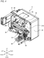
- FIG. 4 illustrates the main body 3 in a state where the outer decorative plate 2 is removed.
- the main body 3 includes a main body base 31, a cover portion 32, a supply roll bearing portion 33, a winding roll bearing portion 34, a bearing portion 35, a support shaft 36, the cylindrical guide body 38, the thermal head 39, a head driving unit 311, a mechanism driving unit 312, and the like.
- the main body base 31 is formed in a substantially rectangular shape in a front view, and a front surface 31A thereof faces the back surface 41B of the cassette base 41 in the state where the cassette 4 is mounted.
- the cover portion 32 is provided on a back surface side of the main body base 31, and is formed in a substantially rectangular parallelepiped box shape.
- the cover portion 32 surrounds and protects the mechanism driving unit 312 which will be described later and which is provided on the back surface side of the main body base 31.
- the supply roll bearing portion 33 and the winding roll bearing portion 34 are provided at positions on the front surface 31A of the main body base 31 respectively corresponding to the supply roll shaft 43 and the winding roll shaft 44 of the cassette 4.
- the supply roll bearing portion 33 supports the supply roll shaft 43 in a state where a tip end of the supply roll shaft 43 abuts on the supply roll bearing portion 33, and transmits a rotational driving force to the supply roll shaft 43 so that a ribbon supply roll (not shown) can be wound therearound.
- the winding roll bearing portion 34 supports the winding roll shaft 44 in a state where a tip end of the winding roll shaft 44 abuts on the winding roll bearing portion 34, and transmits a rotational driving force to the winding roll shaft 44 so that a ribbon winding roll (not shown) can be wound therearound.
- the bearing portion 35 is provided at a position on the front surface 31A of the main body base 31 corresponding to the guide roller 45 of the cassette 4.
- the bearing portion 35 rotatably supports the guide roller 45 by engaging with a tip end portion 45A of the guide roller 45.
- the support shaft 36 is provided at a position on the front surface 31A of the main body base 31 corresponding to the guide roller 46 of the cassette 4.
- the support shaft 36 is inserted into a central shaft hole of the guide roller 46 and rotatably supports the guide roller 46.
- the cylindrical guide body 38 is provided in a central upper portion, between the supply roll bearing portion 33 and the winding roll bearing portion 34, of the front surface 31A, and is provided at a position corresponding to the locating shaft 50 of the cassette 4.
- the cylindrical guide body 38 is formed in a substantially cylindrical shape extending forward from the front surface 31A, and the locating shaft 50 can be inserted into the cylindrical guide body 38 from a front.
- the cylindrical guide body 38 includes a pair of guide grooves 380 in an upper portion and a lower portion. Each of the guide grooves 380 sequentially includes an inclined portion 381, a straight portion 382, and an engaged hole 383 from a front side to a rear side.
- the inclined portion 381 is formed in a linear shape in a plan view, and the linear shape is inclined toward a rear right side with respect to an axis from a front end of the cylindrical guide body 38.
- the straight portion 382 is formed in a linear shape extending rearward from a rear end of the inclined portion 381, and is shorter than the inclined portion 381.
- the engaged hole 383 is bent leftward from a rear end of the straight portion 382, and is formed in a substantially rectangular shape in a plan view.
- a width of the guide groove 380 may be any width as long as balls 57 and 58, which will be described later, of the locating shaft 50 can be guided.
- the thermal head 39 includes a plurality of thermoelectric elements arranged in the front-rear direction.
- the head driving unit 311 is provided on a lower side of the front surface 31A, and supports the thermal head 39 such that the thermal head 39 can move in the left-right direction and the up-down direction.
- the mechanism driving unit 312 is provided on the back surface side of the main body base 31, and includes a plurality of actuators such as various motors.
- the mechanism driving unit 312 respectively drives the supply roll bearing portion 33, the winding roll bearing portion 34, the head driving unit 311, and the thermal head 39 based on control commands received from a controller (not shown).
- the controller may be provided in the printing device 1, or may be provided in a terminal (not shown) that is connected to the printing device 1 to be able to communicate with the printing device 1 in a wired or wireless manner.
- the locating shaft 50 includes a holder 51, a guide shaft 53, a fixing ring 52, a cap 54, a center shaft 55, the release button 56, the balls 57 and 58, a cylindrical collar 61, a release spring 62, a lock spring 63, and the like.
- the holder 51, the guide shaft 53, the fixing ring 52, the cap 54, the release button 56, and the cylindrical collar 61 are each made of a resin, and the center shaft 55 and the balls 57 and 58 are each made of a metal, but materials are not limited to these material.
- the holder 51 is formed in a short axis cylindrical shape extending in the left-right direction.
- a fixing flange 511 is provided on a right side of an outer peripheral surface of the holder 51.
- the fixing flange 511 is formed in a substantially triangular shape in a right side view, and includes a pair of fixing holes 513 (see FIG. 9 ).
- a front surface of the fixing flange 511 abuts on the back surface 41B of the cassette base 41.
- the fixing flange 511 is fixed to the back surface 41B of the cassette base 41 by two screws 512 through the pair of fixing holes 513.
- the guide shaft 53 is formed in a long axis cylindrical shape extending in the front-rear direction, and is coaxially inserted and disposed inside the holder 51.
- the guide shaft 53 includes a guide hole 531 therein.
- the guide hole 531 extends in the front-rear direction.
- the guide shaft 53 protrudes and extends rearward from a rear end portion of the holder 51.
- a diameter-reduced portion 532 whose diameter is reduced toward an inner side in a radial direction is provided on an outer peripheral surface of the guide shaft 53 on a front end side.
- a locking ring 65 is fixed to a position on an outer peripheral surface of the guide shaft 53 close to a rear side of the diameter-reduced portion 532.
- the locking ring 65 protrudes from the outer peripheral surface of the guide shaft 53 toward an outer side in the radial direction.
- the locking ring 65 abuts on an upper portion of a front end portion of the holder 51 from a front.
- a through hole 533 is provided on the outer peripheral surface of the guide shaft 53 behind the locking ring 65.
- the through hole 533 penetrates the guide shaft 53 in the up-down direction orthogonal to a length direction of the guide shaft 53.
- a substantially columnar pin 67 is attachably and detachably inserted into and fixed to the through hole 533 from a lower portion.
- a stepped portion 536 is provided to be closer to a rear end side than a central portion of the guide shaft 53 in the length direction.
- the stepped portion 536 has a substantially cylindrical shape having a diameter reduced toward the inner side in the radial direction and having a predetermined length.
- a pair of upper and lower holes 534 and 535 are provided in the stepped portion 536.
- the holes 534 and 535 are round holes and penetrate in the up-down direction.
- a diameter of each of the holes 534 and 535 may be any diameter as long as a respective one of the balls 57 and 58 to be described later can be inserted therethrough in the up-down direction.
- the fixing ring 52 has substantially the same diameter as that of the holder 51, and is formed in a short axis cylindrical shape extending in the left-right direction.
- the fixing ring 52 is mounted on an outer side of the guide shaft 53, and is fixed to the guide shaft 53 by a fixing screw 521 in a state of abutting on the rear end portion of the holder 51.
- the fixing ring 52 is integrated with the guide shaft 53.
- the fixing ring 52 restricts forward movement of the guide shaft 53 by abutting on the rear end portion of the holder 51.
- the locking ring 65 restricts rearward movement of the guide shaft 53 by abutting on the front end portion of the holder 51. Therefore, the guide shaft 53 is located in the front-rear direction with respect to the holder 51.
- the cap 54 is formed in a substantially cylindrical shape extending in the front-rear direction.
- the cap 54 includes a guide hole 541 therein.
- the cap 54 is coaxially mounted to the rear end side of the guide shaft 53. As a result, the guide hole 541 and the guide hole 531 of the guide shaft 53 coaxially communicate with each other.
- the center shaft 55 is formed in a rod shape extending in the front-rear direction.
- the center shaft 55 is coaxially inserted and disposed inside the guide hole 531 of the guide shaft 53 and the guide hole 541 of the cap 54, and is supported to be movable along the length direction of the guide shaft 53 and the cap 54.
- a front end side of the center shaft 55 protrudes forward from the diameter-reduced portion 532 of the guide shaft 53.
- a button fixing portion 551 is provided at a front end portion of the center shaft 55.
- a recessed portion 552 whose diameter is reduced toward an inner side in the radial direction is provided on an outer peripheral surface of a substantially central portion of the center shaft 55 in the front-rear direction.
- the release button 56 is formed in a substantially columnar shape having a short axis and extending in the front-rear direction, and is fixed to the button fixing portion 551.
- a substantially ring-shaped groove portion 561 recessed forward is provided in a rear end surface of the release button 56.
- the balls 57 and 58 are disposed inside the holes 534 and 535 of the guide shaft 53, respectively.
- the balls 57 and 58 are in contact with an outer peripheral surface of the center shaft 55 in the guide hole 531 of the guide shaft 53, and slide on the outer peripheral surface of the center shaft 55 as the center shaft 55 moves.
- the cylindrical collar 61 is formed in a short axis cylindrical shape extending in the front-rear direction, and is mounted on an outer peripheral surface of the stepped portion 536 of the guide shaft 53.
- the cylindrical collar 61 is provided with a pair of upper and lower exposure holes 611 and 612.
- the exposure holes 611 and 612 are provided at positions corresponding to the pair of upper and lower holes 534 and 535 of the guide shaft 53.
- a diameter of each of the exposure holes 611 and 612 is smaller than the diameter of a respective one of the balls 57 and 58.
- the cylindrical collar 61 can allow a part of each of the balls 57 and 58 to protrude outward from a respective one of the exposure holes 611 and 612, and can prevent the balls 57 and 58 from falling out of the exposure holes 611 and 612 respectively.
- the release spring 62 is a cylindrical compression coil spring extending in the front-rear direction, and is a push-back spring that performs pushing back in a reverse direction of an axial direction when a load is applied in the axial direction.
- the release spring 62 is mounted on the front end side of the center shaft 55.
- a front end portion of the release spring 62 is inserted into the groove portion 561 of the release button 56 from a rear side, and abuts against a wall surface of the groove portion 561 on a back side.
- a rear end portion of the release spring 62 abuts against a front end portion of the guide shaft 53.
- the lock spring 63 is a torsion coil spring, and is mounted on an outer peripheral surface of the diameter-reduced portion 532 on the front end side of the guide shaft 53.
- One end portion 631 of the lock spring 63 on a front end side is fixed to the diameter-reduced portion 532 of the guide shaft 53.
- the other end portion 632 of the lock spring 63 on a rear end side is locked to a locked portion (not shown) provided on an inner peripheral surface of the insertion hole 425 in the upper support portion 422 of the handle 42.
- the lock spring 63 is wound in a clockwise direction (clockwise) about an axis when viewed from the front end side.
- the locating shaft 50 can be displaced between the first state and the second state by an operation of the release button 56.
- the locating shaft 50 shown in FIG. 7 is in the first state.
- the release spring 62 biases the release button 56 forward.
- the center shaft 55 moves forward integrally with the release button 56.
- a portion of the outer peripheral surface of the center shaft 55 behind the recessed portion 552 is located at positions of the balls 57 and 58.
- the balls 57 and 58 are pushed toward an outer side in the radial direction by the outer peripheral surface of the center shaft 55, and a part of each of the balls 57 and 58 protrudes from a respective one of the exposure holes 611 and 612.
- a method for inserting the locating shaft 50 into the cylindrical guide body 38 and locking the locating shaft 50 will be described.
- the user grips the handle 42 of the cassette 4 and disposes the cassette 4 on a front side of the main body 3.
- the back surface 41B of the cassette base 41 of the cassette 4 faces the front surface 31A of the main body base 31 of the main body 3.
- the locating shaft 50 on a side of the back surface 41B faces the cylindrical guide body 38 on a side of the front surface 31A.
- the user inserts a tip end side of the locating shaft 50 into the cylindrical guide body 38. Since the locating shaft 50 is in the first state, a part of the ball 57 protrudes upward from the upper exposure hole 611, and a part of the ball 58 protrudes downward from the lower exposure hole 612. The user inserts a part of the ball 57 protruding from the upper exposure hole 611 into a front end side of the upper guide groove 380 of the cylindrical guide body 38. At the same time, the user inserts a part of the ball 58 protruding from the lower exposure hole 612 into a front end side of the lower guide groove 380 of the cylindrical guide body 38.
- each of the balls 57 and 58 moves along the inclined portion 381 of the guide groove 380.
- Each of the balls 57 and 58 moves along the inclined portion 381, so that each of the balls 57 and 58 rotates in the clockwise direction (clockwise) about the center shaft 55 when viewed from a front end side.
- the guide shaft 53 and the cap 54 rotate in the clockwise direction (clockwise) about the center shaft 55 integrally with the balls 57 and 58 against a spring force of the lock spring 63 when viewed from the front end side.
- guiding and locking of the locating shaft 50 can be simultaneously performed by only one action of inserting the locating shaft 50 into the cylindrical guide body 38, so that operability can be improved.
- the locked state can be easily released.
- a method for releasing the locking of the locating shaft 50 to pull out the locating shaft 50 from the cylindrical guide body 38 will be described.
- the user presses down the release button 56 with a thumb of a hand with which the handle 42 is gripped while gripping the handle 42 of the cassette 4.
- the center shaft 55 is pushed rearward, so that a positional relationship between the recessed portion 552 and the balls 57 and 58 changes, and the locating shaft 50 changes from the first state (see FIG. 7 ) to the second state (see FIG. 8 ).
- the user pulls out the locating shaft 50 from the cylindrical guide body 38 by pulling the handle 42 forward.
- the printing device 1 includes the main body 3 and the cassette 4.
- the front surface 31A of the main body 3 supports the thermal head 39.
- the cassette 4 includes the plate-shaped cassette base 41, the supply roll shaft 43, and the winding roll shaft 44.
- the supply roll shaft 43 is provided on a left side of the back surface 41B of the cassette base 41 facing the front surface 31A, and rotatably supports the ribbon supply roll (not shown).
- the winding roll shaft 44 is provided on a right side of the back surface 41B, and rotatably supports the ribbon winding roll (not shown).
- the cassette 4 is attached to and detached from the front surface 31A of the main body 3 along the axis direction of the supply roll shaft 43 and the winding roll shaft 44.
- the printing device 1 performs printing by transferring ink of the ink ribbon onto a print medium duet to heating of the thermal head 39, and the ink ribbon is fed out from the ribbon supply roll and wound around the ribbon winding roll through the thermal head 39.
- the printing device 1 further includes the locating shaft 50, the cylindrical guide body 38, the balls 57 and 58, the center shaft 55, and the release button 56.
- the locating shaft 50 is provided in the back surface 41B of the cassette base 41 of the cassette 4.
- the cylindrical guide body 38 is provided at the position on the front surface 31A of the main body 3 facing the locating shaft 50, and guides and locates the locating shaft 50 to the predetermined position on the side of the front surface 31A along the axis direction.
- the balls 57 and 58 are provided in the locating shaft 50, and locks the locating shaft 50 to the cylindrical guide body 38 in a state where the locating shaft 50 is located at the predetermined position by the cylindrical guide body 38.
- the release button 56 is pressed down by the user to release the locking. When the release button 56 is pressed down, the center shaft 55 is pushed in, the balls 57 and 58 can retract, and the locking is released.
- the balls 57 and 58 are provided in the cylindrical guide body 38 provided in the front surface 31A of the main body 3, so that a limited space in the printing device 1 can be effectively used. Since the locating shaft 50 can be locked to the cylindrical guide body 38 in a state where the locating shaft 50 is guided and located to the predetermined position by the cylindrical guide body 38, usability can be improved.
- the locating shaft 50 is provided in the central upper portion, between the supply roll shaft 43 and the winding roll shaft 44, of the back surface 41B of the cassette base 41. Therefore, the cassette base 41 is supported in a balanced manner in the left-right direction with respect to the front surface 31A of the main body 3.
- a space between the supply roll shaft 43 and the winding roll shaft 44 is limited by a thickness of each of the ribbon supply roll and the ribbon winding roll, but the limited space in the printing device 1 can be more effectively used by providing the locating shaft 50 in a dead space above the supply roll shaft 43 and the winding roll shaft 44.
- the cassette 4 includes the handle 42.
- the handle 42 is provided on the front surface 41A of the cassette base 41, and can be gripped by the user. Since the release button 56 is provided in the handle 42, a release operation for the locking can be easily performed.
- the locating shaft 50 is an example of a "shaft” in the present invention.
- the exposure holes 611 and 612 are examples of an “opening portion” in the present invention.
- the balls 57 and 58 are examples of a “spherical body” in the present invention.
- the release spring 62 is an example of a “first biasing member” in the present invention, and the lock spring 63 is an example of a “second biasing member” in the present invention.
- the release button 56 is an example of an "operation unit” in the present invention.
- the front surface 31A of the main body base 31 of the main body 3 is an example of a "head support surface” in the present invention.
- the back surface 41B of the cassette base 41 of the cassette 4 is an example of a "facing surface” in the present invention.
- the printing device 1 performs printing by allowing the packaging material to pass through the lower portion from the left to the right, but may perform printing by allowing the packaging material to pass through the lower portion from the left to the right.
- a configuration of the head driving unit 311 for the thermal head 39 can also be freely changed.
- the locating shaft 50 is provided in the central upper portion, between the supply roll shaft 43 and the winding roll shaft 44, of the back surface 41B of the cassette base 41, but depending on positions of the thermal head 39 and the head driving unit 311, the locating shaft 50 may be provided in a dead space formed in a vicinity of a center or in a central lower portion of the back surface 31B.
- the position of the cylindrical guide body 38 may be changed accordingly.
- a position of the release button 56 provided in the handle 42 may also be changed depending on the position of the locating shaft 50.
- the operation unit may release locking by changing a state of the center shaft 55 by a lever or a trigger disposed on a back surface of the handle 42.
- the balls 57 and 58 are provided on a top and a bottom of the outer peripheral surface of the guide shaft 53 to be able to protrude and retract, but the number of balls may be one, or may be two or more.
- the positions of the balls 57 and 58 may be positions other than the top and the bottom of the outer peripheral surface of the guide shaft 53.
- each of the guide shaft 53 and the cap 54 rotates in the clockwise direction about the center shaft 55 when viewed from the front end side, but the shape of the guide groove 380 may be reversed and each of the guide shaft 53 and the cap 54 may rotate in the counterclockwise direction about the center shaft 55 when viewed from the front end side.
- the lock spring 63 having an opposite winding direction may be used.
- the cylindrical collar 61 is mounted on the stepped portion 536 of the guide shaft 53, and each of the balls 57 and 58 is partially exposed to the outside while being prevented from falling out by a respective one of the exposure holes 611 and 612 provided in the cylindrical collar 61, but each of the balls 57 and 58 may be partially exposed to the outside while the balls 57 and 58 may be prevented from falling out, for example, by omitting the cylindrical collar 61 and reducing the diameter of each of the holes 534 and 535.
- the cap 54 is coaxially mounted to a rear end portion of the guide shaft 53, but a guide shaft in which the guide shaft 53 is integrated with the cap 54 may be used.
- FIGs. 14 to 16 a second embodiment of the present invention will be described with reference to FIGs. 14 to 16 . Since the same reference numerals in the drawings denote the same configurations as those in the above embodiment unless there is any additional description, detailed descriptions thereof will be omitted.
- a locating shaft 500 and a cylindrical guide body 138 are used instead of the locating shaft 50 and the cylindrical guide body 38.
- the locating shaft 500 includes the holder 51, the guide shaft 53, the fixing ring 52, the cap 54, a center shaft 550, the release button 56, the balls 57 and 58, and the cylindrical collar 61.
- the locating shaft 500 does not include the release spring 62 and the lock spring 63.
- the center shaft 550 is formed in a rod shape extending in a front-rear direction.
- the center shaft 550 includes a first shaft 5501 and a second shaft 5502 arranged side by side in the front-rear direction, and a compression spring 5503 that connects the two shafts 5501 and 5502.
- the center shaft 550 is coaxially inserted and disposed inside the guide hole 531 of the guide shaft 53 and the guide hole 541 of the cap 54, and is supported to be movable along a length direction of the guide shaft 53 and the cap 54.
- a front end side of the center shaft 550 (first shaft 5501) protrudes forward from the diameter-reduced portion 532 of the guide shaft 53.
- the button fixing portion 551 is provided at a front end portion of the center shaft 550 (first shaft 5501).
- the recessed portion 552 whose diameter is reduced toward an inner side in a radial direction is provided on an outer peripheral surface of a substantially central portion of the center shaft 550 (first shaft 5501) in the front-rear direction.
- a biasing spring 5504 is provided which includes one end connected to the first shaft 5501 and the other end connected to the cap 54 and which biases the first shaft 5501 rearward.
- a spring force (spring constant) of the biasing spring 5504 is set to be smaller than a spring force (spring constant) of the compression spring 5503.
- the balls 57 and 58 are disposed inside the holes 534 and 535 of the guide shaft 53, respectively.
- the balls 57 and 58 are in contact with an outer peripheral surface of the center shaft 550 (first shaft 5501) in the guide hole 531 of the guide shaft 53, and slide on the outer peripheral surface of the center shaft 550 (first shaft 5501) as the center shaft 550 (first shaft 5501) moves.
- the cylindrical collar 61 is formed in the short axis cylindrical shape extending in the front-rear direction, and is mounted on the outer peripheral surface of the stepped portion 536 of the guide shaft 53 similarly to the above embodiment.
- the cylindrical collar 61 is provided with a pair of upper and lower exposure holes 611 and 612. As a result, the cylindrical collar 61 can allow a part of each of the balls 57 and 58 to protrude outward from a respective one of the exposure holes 611 and 612, and can prevent the balls 57 and 58 from falling out of the exposure holes 611 and 612 respectively.
- a position of each of the guide shaft 53 and the cap 54 centered on the axis is fixed with respect to the holder 51, and the guide shaft 53 and the cap 54 are attached not to be rotatable.
- the cylindrical guide body 138 is formed in a substantially cylindrical shape extending forward from the front surface 31A, and the locating shaft 500 can be inserted into the cylindrical guide body 138 from a front.
- the cylindrical guide body 138 includes the pair of engaged holes 383 and an abutment portion 384.
- Each of the engaged holes 383 is formed in a circular shape in a plan view.
- the abutment portion 384 is provided inside the cylindrical guide body 138, and is disposed, in the front-rear direction, at a position where a rear end of the cap 54 of the locating shaft 500 abuts on the abutment portion 384 in the state where the cassette 4 is mounted to the main body 3.
- the pair of engaged holes 384 are disposed at positions facing the exposure holes 611 and 612.
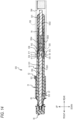
- the locating shaft 500 shown in FIG. 14 is in an initial state before the cassette 4 is mounted to the main body 3.
- the release button 56 is in a state of being pushed rearward, and inside the guide hole 531 of the guide shaft 53, the center shaft 550 is biased by the biasing spring 5504 to move rearward integrally with the release button 56.
- the positions of the balls 57 and 58 face the recessed portion 552 of the outer peripheral surface of the center shaft 550 (first shaft 5501).
- the balls 57 and 58 are movable inward in the radial direction, the balls 57 and 58 respectively move inward from the exposure holes 611 and 612 by being pushed in from the outside.
- the second shaft 5502 is pushed rearward by the compression spring 5503, and a rear end portion of the second shaft 5502 is in a state of being exposed and protruding from a guide hole of the cap 54.
- a user grips the handle 42 of the cassette 4 and disposes the cassette 4 on the front side of the main body 3 in order to mount the cassette 4 to the main body 3.
- the back surface 41B of the cassette base 41 of the cassette 4 faces the front surface 31A of the main body base 31 of the main body 3.
- the locating shaft 500 on the side of the back surface 41B faces the cylindrical guide body 138 on the side of the front surface 31A.
- the user inserts a tip end side of the locating shaft 500 into the cylindrical guide body 138. Since the locating shaft 500 is in the initial state, the balls 57 and 58 do not respectively protrude outward from the exposure holes 611 and 612, and do not interfere with an inner wall of the cylindrical guide body 138. Therefore, the user can smoothly insert the locating shaft 500 into the cylindrical guide body 138 without feeling a resistance.
- the user moves the cassette 4 toward a side of the main body 3 in a state of gripping the handle 42.
- a rear end of the second shaft 5502 abuts on the abutment portion 384, and the second shaft 5502 moves forward with respect to the cap 54.
- the first shaft 5501 also receives a force to move forward.
- the center shaft 550 attempts to move forward, so that the balls 57 and 58 abut against a portion of the outer peripheral surface of the center shaft 550 (first shaft 5501) behind the recessed portion 552. Therefore, the balls 57 and 58 are pushed toward an outer side in the radial direction by the outer peripheral surface of the center shaft 550 (first shaft 5501), and a part of each of the balls 57 and 58 attempts to protrude from a respective one of the exposure holes 611 and 612. However, in the middle of insertion, each of the balls 57 and 58 cannot completely protrude due to interfering with the inner wall of the guide cylinder 138.
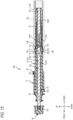
- the balls 57 and 58 are pushed toward the outer side in the radial direction by an outer peripheral surface of the portion of the outer peripheral surface of the first shaft 5501 behind the recessed portion 552, and a part of each of the balls 57 and 58 protrudes from a respective one of the engaged holes 384 via a respective one of the exposure holes 611 and 612 to lock the locating shaft 500.
- the release button 56 By movement of the center shaft 550 (first shaft 5501), the release button 56 also moves forward from the guide shaft 53 and the cap 54 to transition to a state where the release button 56 can be pressed.
- the biasing spring 5504 is in a compressed state.
- the locating shaft 50 is in a locked state of being locked to the cylindrical guide body 38, and the cassette 4 is mounted to the main body 3.
- guiding and locking of the locating shaft 500 can be simultaneously performed by only one action of inserting the locating shaft 500 into the cylindrical guide body 138, so that operability can be improved.
- the locked state can be easily released.
- a method for releasing the locking of the locating shaft 500 to pull out the locating shaft 500 from the cylindrical guide body 138 will be described.
- the user presses the release button 56 rearward against the spring force of the compression spring 5503 with a thumb of a hand with which the handle 42 is gripped while gripping the handle 42 of the cassette 4.
- the first shaft 5501 is pushed rearward, so that the positional relationship between the recessed portion 552 and the balls 57 and 58 changes, and the locating shaft 500 changes from the locked state (see FIG. 15 ) to a released state (see FIG. 16 ).
- the user pulls out the locating shaft 500 from the cylindrical guide body 138 by pulling the handle 42 forward.
- the balls 57 and 58 do not protrude from the beginning of mounting, the balls 57 and 58 almost do not interfere with the cylindrical guide body 138. Therefore, the user can mount the cassette 4 to the main body 3 with a small force without feeling the resistance. Since the interference does not occur, damage due to wear or the like of the balls 57 and 58 can be made extremely small.
- the locating shaft 500 is an example of the "shaft” in the present invention.
- the exposure holes 611 and 612 are examples of an “opening portion” in the present invention.
- the balls 57 and 58 are examples of a “spherical body” in the present invention.
- the release button 56 is an example of an “operation unit” in the present invention.
- the compression spring 5503 is an example of a "third biasing member” in the present invention.
Landscapes
- Impression-Transfer Materials And Handling Thereof (AREA)
- Electronic Switches (AREA)
Abstract
Description
- The present invention relates to a printing device.
-
Patent Literature 1 discloses a thermal transfer type printing device in which a ribbon cassette supporting an ink ribbon is attached to and detached from a printing device main body. Two locating guide shafts and a slider operation unit are provided on a cassette base of the ribbon cassette. The two locating guide shafts are provided at both left and right ends of the cassette base, and extend parallel to an attachment and detachment direction of the ribbon cassette. The slider operation unit is provided to be movable in a left-right direction. Inside the cassette base, an interlocking bar is provided to be movable in the left-right direction in conjunction with the slider operation unit, and locking claws are respectively provided at both left and right end portions of the interlocking bar. - When the ribbon cassette is mounted to the printing device main body, the two locating guide shafts are respectively inserted and fitted into two positioning guide holes provided in the printing device main body. After the ribbon cassette is mounted, the two locking claws move in the left-right direction in conjunction with the slider operation unit via the interlocking bar by an operation of the slider operation unit, so that the two locking claws are respectively locked to two locked portions provided on a printing device main body side, and a mounted state is locked.
- Patent Literature 1:
JP2018-202630A - In the printing device described in
Patent Literature 1, a guide mechanism including the locating guide shafts and the positioning guide holes, and a locking mechanism including the locking claws and the locked portions are provided at different positions independently of each other. Therefore, a problem arises that a space in the device is narrow. - An object of the present invention is to provide a printing device in which a wide space in the device can be used.
- A printing device of
claim 1 includes: a main body having a head support surface on which a thermal head is supported; and a cassette including a plate-shaped cassette base, a supply roll shaft, and a winding roll shaft, and detachably attached to the head support surface of the main body along an axis direction of the supply roll shaft and the winding roll shaft, the supply roll shaft rotatably supporting a ribbon supply roll and being provided on one side, in a predetermined direction, of a facing surface of the cassette base facing the head support surface, and the winding roll shaft rotatably supporting a ribbon winding roll and being provided on an other side, in the predetermined direction, of the facing surface, in which the printing device is configured to perform printing by transferring ink of an ink ribbon onto a print medium due to heating of the thermal head, and the ink ribbon is fed out from the ribbon supply roll and wound around the ribbon winding roll through the thermal head, and in which the printing device further includes: a guided portion provided on the facing surface of the cassette base; a guide portion provided at a position facing the guided portion on the head support surface of the main body, and configured to guide and locate the guided portion to a predetermined position on a side of the head support surface along the axis direction; a lock unit provided in the guided portion and configured to lock the guided portion to the guide portion in a state where the guided portion is located at the predetermined position by the guide portion; and a release unit configured to release locking performed by the lock unit. According to the printing device according to the aspect, since the lock unit is provided at the guide portion provided on the head support surface of the main body, the guide portion and the lock unit can be provided at the same position. Therefore, the printing device can effectively use a limited space in the printing device as compared with a configuration in which the guide portion and the lock unit are provided at different positions. Since the guided portion can be locked to the guide portion in the state where the guided portion is guided and located to the predetermined position by the guide portion, guiding and locking operations of the guided portion can be performed by a series of actions. As a result, the printing device can improve usability. The "predetermined position" means a predetermined position of the guided portion with respect to the guide portion in a state where the cassette is normally mounted to the main body in an attachment and detachment direction of the cassette. - The guided portion of the printing device of
claim 2 may be provided between the supply roll shaft and the winding roll shaft in the predetermined direction on the facing surface of the cassette base, and may be provided, in a state where the cassette is mounted, at a location on a side opposite to the thermal head with respect to the supply roll shaft in an orthogonal direction that is orthogonal to the predetermined direction and the axis direction. Therefore, the cassette base is supported in a balanced manner in the predetermined direction with respect to the head support surface of the main body. A space between the supply roll shaft and the winding roll shaft is limited by a thickness of each of the ribbon supply roll and the ribbon winding roll, but the limited space in the printing device can be more effectively used by providing the guided portion in a dead space on the side opposite to the thermal head with respect to the supply roll shaft in the orthogonal direction. - The printing device of
claim 3 may further include a grip portion provided on an outer surface of the cassette base on a side opposite to the facing surface, and configured to be gripped by a user, and the release unit may be provided in the grip portion. In the printing device according to the aspect, since the release unit is provided in the grip portion, the user can perform a release operation while gripping the grip portion. As a result, the aspect can provide the printing device having high usability. - The guided portion of the printing device of
claim 4 may include a rod-shaped shaft extending from the facing surface toward a side of the head support surface in parallel with the axis direction, the guide portion may include a cylindrical guide body extending from the head support surface toward a side of the facing surface in parallel with the axis direction, and configured to guide and locate the shaft to the predetermined position by inserting the shaft inside the cylindrical guide body, the lock unit may include: an engagement portion provided to be cable of protruding from an opening portion from an inner side toward an outer side of the shaft in a radial direction, and being engageable with an engaged hole through the opening portion in a state where the shaft is guided to the predetermined position by the cylindrical guide body, the opening portion being provided on an outer peripheral surface of the shaft, and the engaged hole is provided in an outer peripheral surface of the cylindrical guide body, and the release unit may be provided in the shaft, and may be configured to move the engagement portion to the inner side in the radial direction to disengage the engagement portion from the engaged hole. According to the printing device according to the aspect, the shaft is automatically guided to the predetermined position by inserting the shaft into the cylindrical guide body. The engagement portion engages with the engaged hole in a state where the shaft is guided to the predetermined position, so that the shaft is locked to the cylindrical guide body. Guiding and locking can be simultaneously performed by one action of inserting the shaft into the cylindrical guide body, so that operability is improved. The locking can be easily released by disengaging the engagement portion from the engaged hole. - The shaft of the printing device of claim 5 may include: a cylindrical holder fixed to the facing surface and extending in parallel with the axis direction toward the side of the head support surface; and a cylindrical guide shaft coaxially disposed in the holder and extending from a tip end portion of the holder toward the side of the head support surface, the tip end portion facing the side of the head support surface, the release unit may include: a rod-shaped center shaft disposed in the holder and the guide shaft and provided to be movable along a length direction of the holder and the guide shaft, the lock unit may include: a first biasing member configured to constantly bias the center shaft toward a side of the cassette base, the engagement portion may be a spherical body, and may be provided between the guide shaft and the center shaft, the spherical body being disposed to be slidable on an outer peripheral surface of the center shaft, and a part of the spherical body being exposed from the opening portion to engage with the engaged hole in a first state where the spherical body is in contact with the outer peripheral surface of the center shaft moved toward the side of the cassette base by the first biasing member, a recessed portion recessed toward an inner side of the center shaft in a radial direction may be provided on the outer peripheral surface of the center shaft at a position closer to the side of the cassette base than a position with which the part of the spherical body is in contact in the first state, and the release unit may be configured to shift from the first state to a second state where the spherical body is in contact with the recessed portion and to disengage the spherical body from the engaged hole by moving the center shaft toward the side of the head support surface against a biasing force of the first biasing member and disposing the recessed portion at a position of the spherical body, to release the locking. According to the printing device according to the aspect, by moving the center shaft within the guide shaft and causing the center shaft to be the first state, a part of the spherical body can be exposed from the opening portion and can engage with the engaged hole, and the shaft can be locked to the cylindrical guide body. By switching the center shaft from the first state to the second state, the spherical body moves inward from the opening portion to be disengaged from the engaged hole, so that the locking can be easily released.
- The guide shaft of the printing device of claim 6 may be supported in the holder to be rotatable about an axis, and the printing device may include: a second biasing member provided in the holder and configured to constantly bias the guide shaft in one direction about the axis; and a guide groove provided on the outer peripheral surface of the cylindrical guide body, extending from one end portion of the cylindrical guide body toward the engaged hole to be inclined in a direction opposite to the one direction about the axis, and configured to guide the part of the spherical body exposed from the opening portion from the one end portion to the engaged hole, the one end portion facing the side of the cassette base. The shaft is inserted along an inside of the cylindrical guide body, and a part of the spherical body exposed from the opening portion of the shaft is pushed toward the side of the head support surface along the guide groove. At this time, since the spherical body is guided along the guide groove in a direction opposite to a biasing direction of the second biasing member, the guide shaft rotates in the same direction together with the spherical body. When the spherical body is guided to the engaged hole, the guide shaft is biased in the one direction about the axis and pulled back by the second biasing member, and the spherical body engages with the engaged hole to perform the locking. As a result, the guiding and the locking can be performed by only one action of inserting the shaft into the cylindrical guide body.
- The second biasing member of the printing device of claim 7 may be a torsion coil spring. As a result, a biasing force can be easily applied to the guide shaft in the one direction about the axis.
- The release unit of the printing device of claim 8 may include an operation unit fixed to one end portion of the center shaft located on a side of the holder, and configured to push the center shaft toward the side of the head support surface. Since the user can release the locking only by pushing the operation unit toward the side of the head support surface, the release operation can be performed more easily. Therefore, the printing device can improve the usability.
- The shaft of the printing device of claim 9 may include: a cylindrical holder fixed to the facing surface and extending in parallel with the axis direction toward the side of the head support surface; and a cylindrical guide shaft coaxially disposed in the holder and extending from a tip end portion of the holder toward the side of the head support surface, the tip end portion facing the side of the head support surface the release unit may include: a rod-shaped first shaft and a rod-shaped second shaft disposed in the holder and the guide shaft, and coaxially provided to be movable along a length direction of the holder and the guide shaft, the cylindrical guide body may include an abutment portion configured to, in a state where the cassette is mounted to the main body, abut against the second shaft to restrict the guide shaft from moving toward the side of the head support surface in the length direction of the guide shaft, the lock unit may include: a third biasing member disposed between the first shaft and the second shaft, and configured to bias the first shaft toward a side of the cassette base in a state where the cassette is mounted to the main body, the engagement portion may be a spherical body, and may be provided between the first shaft and the center shaft, the spherical body being disposed to be slidable on an outer peripheral surface of the first shaft, and a part of the spherical body being exposed from the opening portion to engage with the engaged hole in a locked state where the spherical body is in contact with the outer peripheral surface of the first shaft moved toward the side of the cassette base by the third biasing member, a recessed portion recessed toward an inner side of the first shaft in a radial direction may be provided on the outer peripheral surface of the first shaft at a position closer to the side of the cassette base than a position with which the part of the spherical body is in contact in the locked state, and the release unit may be configured to shift from the locked state to a released state where the spherical body is in contact with the recessed portion and to disengage the spherical body from the engaged hole by moving the first shaft toward the side of the head support surface against a biasing force of the third biasing member and disposing the recessed portion at a position of the spherical body, to release the locking. According to the printing device according to the aspect, by moving the first shaft within the guide shaft and causing the first shaft to be the locked state, a part of the spherical body can be exposed from the opening portion and can engage with the engaged hole, and the shaft can be locked to the cylindrical guide body. By switching the first shaft from the locked state to the released state, the spherical body moves inward from the opening portion to be disengaged from the engaged hole, so that the locking can be easily released.
-
- [
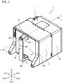
FIG. 1] FIG. 1 is a perspective view of aprinting device 1. - [
FIG. 2] FIG. 2 is a perspective view of theprinting device 1 in a state where acassette 4 is pulled out forward from amain body 3. - [
FIG. 3] FIG. 3 is a perspective view of thecassette 4. - [
FIG. 4] FIG. 4 is a perspective view of themain body 3. - [
FIG. 5] FIG. 5 is a cross-sectional view taken along a line I-I shown inFIG. 1 , when viewed from an arrow direction. - [
FIG. 6] FIG. 6 is a cutaway and partially enlarged perspective view of thecassette 4. - [
FIG. 7] FIG. 7 is a cross-sectional view (first state) of a locatingshaft 50. - [
FIG. 8] FIG. 8 is a cross-sectional view (second state) of the locatingshaft 50. - [
FIG. 9] FIG. 9 is a perspective view showing a state where a tip end side of the locatingshaft 50 is inserted into acylindrical guide body 38. - [
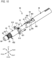
FIG. 10] FIG. 10 is a perspective view showing a state where the locatingshaft 50 is further inserted into thecylindrical guide body 38 from the state inFIG. 9 . - [
FIG. 11] FIG. 11 is a perspective view showing a state where the locatingshaft 50 is further inserted into thecylindrical guide body 38 from the state inFIG. 10 . - [
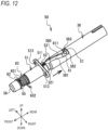
FIG. 12] FIG. 12 is a perspective view showing a state where the locatingshaft 50 is further inserted into thecylindrical guide body 38 from the state inFIG. 11 . - [
FIG. 13] FIG. 13 is a perspective view showing a state where the locatingshaft 50 is locked to thecylindrical guide body 38. - [
FIG. 14] FIG. 14 is a cross-sectional view showing a state where a locatingshaft 50 is inserted into acylindrical guide body 38 in a second embodiment. - [
FIG. 15] FIG. 15 is a cross-sectional view showing a state where the locatingshaft 50 is locked to thecylindrical guide body 38 in the second embodiment. - [
FIG. 16] FIG. 16 is a cross-sectional view showing a state where locking of the locatingshaft 50 is released in the second embodiment. - An embodiment of the present invention will be described with reference to the drawings. In the following description, left and right, front and rear, and up and down indicated by arrows in the drawings are used. A
printing device 1 shown inFIG. 1 can print desired characters and graphics by allowing a belt-shaped packaging material (not shown) fed out from a packaging material supply roll (not shown) to pass through a lower portion from left to right. - A configuration of the
printing device 1 will be described. As shown inFIG. 1 , theprinting device 1 is formed in a substantially rectangular parallelepiped shape, and includes an outerdecorative plate 2. The outerdecorative plate 2 covers an outer peripheral surface of theprinting device 1 around an axis in a front-rear direction, and can be attached to and detached from theprinting device 1. InFIGs. 4 and5 , the outerdecorative plate 2 is not shown. Theprinting device 1 includes amain body 3 and acassette 4 which are separable from each other in the front-rear direction. The outerdecorative plate 2 can be mounted on a side of themain body 3, and thecassette 4 is inserted inside the outerdecorative plate 2. As shown inFIG. 2 , thecassette 4 can be attached to and detached from themain body 3 by being inserted and pulled out along an axis direction (front-rear direction) of asupply roll shaft 43 and a windingroll shaft 44 which are provided on a side of thecassette 4 and which will be described later. - A structure of the
cassette 4 will be described. As shown inFIGs. 2 and3 , thecassette 4 is disposed on a front side of theprinting device 1, and includes acassette base 41, ahandle 42, thesupply roll shaft 43, the windingroll shaft 44, twoguide rollers shaft 50, and the like. - The
cassette base 41 is formed in a substantially rectangular shape in a front view. Thehandle 42 is provided on a side of afront surface 41A of thecassette base 41, and includes agrip portion 421, anupper support portion 422, and alower support portion 423. Thegrip portion 421 is provided at a position spaced forward from afront surface 41A to extend in an up-down direction, and is gripped by a user. Theupper support portion 422 bridges between a central portion of an upper end portion of thecassette base 41 and an upper end portion of thegrip portion 421. Thelower support portion 423 bridges between a central portion of a lower end portion of thecassette base 41 and a lower end portion of thegrip portion 421. As a result, thehandle 42 is provided to bridge, in the up-down direction, between the respective central portions of the upper end portion and the lower end portion of thecassette base 41. Thehandle 42 is gripped by the user when thecassette 4 is to be attached to and detached from themain body 3. Arelease button 56 is provided in an upper portion of a front surface of thegrip portion 421. Therelease button 56 is pressed down from a front by the user in order to release locking to themain body 3 by the locatingshaft 50 to be described later. - As shown in
FIG. 3 , thesupply roll shaft 43 and the windingroll shaft 44 are provided side by side in a left-right direction on aback surface 41B of thecassette base 41 and above a central position in the up-down direction. Thesupply roll shaft 43 is disposed on a left side, and the windingroll shaft 44 is disposed on a right side. Thesupply roll shaft 43 and the windingroll shaft 44 are provided to extend rearward from theback surface 41B, and are each provided to be rotatable about a central axis. One end of a series of belt-shaped ink ribbons (not shown) is fixed to thesupply roll shaft 43 in advance and the ink ribbons are wound around thesupply roll shaft 43 in advance. The other end of the ink ribbons is fixed to the windingroll shaft 44, so that the ink ribbons fed out from thesupply roll shaft 43 are wound into a roll shape. - The
guide roller 45 is provided at a lower left corner portion of theback surface 41B. Theguide roller 46 is provided at a lower right corner portion of theback surface 41B. Theguide rollers back surface 41B, and are each provided to be rotatable about a central axis. The ink ribbons fed out from thesupply roll shaft 43 are finally guided to the windingroll shaft 44 through a conveyance path that is bent by abutting against outer peripheral surfaces of the twoguide rollers - The locating
shaft 50 is provided in a central upper portion, between thesupply roll shaft 43 and the windingroll shaft 44, of theback surface 41B. The position is in a (central in an example) region between thesupply roll shaft 43 and the windingroll shaft 44 in the left-right direction, and is located substantially at an upper end of thecassette base 41 in the up-down direction. The position is a position that does not interfere with feeding out and winding of the ink ribbons regardless of an used amount of the ink ribbons as described later, and does not hinder an operation of athermal head 39 since the position is located, even when thecassette 4 is mounted, on a side opposite to a lower side where thethermal head 39 is located. A throughhole 411 is provided at a position on theback surface 41B where the locatingshaft 50 is provided (seeFIG. 5 ). The throughhole 411 penetrates thecassette base 41 in the front-rear direction, and communicates in the front-rear direction with an insertion hole 425 (seeFIG. 6 ) provided inside theupper support portion 422 of thehandle 42. Theinsertion hole 425 extends in the front-rear direction, and a front end portion thereof is open at the upper portion of the front surface of the grip portion 421 (seeFIG. 1 ). - The locating
shaft 50 is formed in a rod shape having a substantially circular transverse cross section, and is inserted into theinsertion hole 425 and the throughhole 411 in the front-rear direction. The locatingshaft 50 protrudes and extends rearward from theback surface 41B of thecassette base 41. The locatingshaft 50 is inserted into a later-described cylindrical guide body 38 (seeFIG. 3 ) of themain body 3, and is locked in a state of being located at a predetermined position. Therelease button 56 is fixed to a front end portion of the locatingshaft 50. Therelease button 56 protrudes forward from an opening in the upper portion of the front surface of thegrip portion 421. A specific structure of the locatingshaft 50 will be described later. - A structure of the
main body 3 will be described.FIG. 4 illustrates themain body 3 in a state where the outerdecorative plate 2 is removed. As shown inFIG. 4 , themain body 3 includes amain body base 31, acover portion 32, a supplyroll bearing portion 33, a windingroll bearing portion 34, a bearingportion 35, asupport shaft 36, thecylindrical guide body 38, thethermal head 39, ahead driving unit 311, amechanism driving unit 312, and the like. Themain body base 31 is formed in a substantially rectangular shape in a front view, and afront surface 31A thereof faces theback surface 41B of thecassette base 41 in the state where thecassette 4 is mounted. Thecover portion 32 is provided on a back surface side of themain body base 31, and is formed in a substantially rectangular parallelepiped box shape. Thecover portion 32 surrounds and protects themechanism driving unit 312 which will be described later and which is provided on the back surface side of themain body base 31. - The supply
roll bearing portion 33 and the windingroll bearing portion 34 are provided at positions on thefront surface 31A of themain body base 31 respectively corresponding to thesupply roll shaft 43 and the windingroll shaft 44 of thecassette 4. The supplyroll bearing portion 33 supports thesupply roll shaft 43 in a state where a tip end of thesupply roll shaft 43 abuts on the supplyroll bearing portion 33, and transmits a rotational driving force to thesupply roll shaft 43 so that a ribbon supply roll (not shown) can be wound therearound. The windingroll bearing portion 34 supports the windingroll shaft 44 in a state where a tip end of the windingroll shaft 44 abuts on the windingroll bearing portion 34, and transmits a rotational driving force to the windingroll shaft 44 so that a ribbon winding roll (not shown) can be wound therearound. - The bearing
portion 35 is provided at a position on thefront surface 31A of themain body base 31 corresponding to theguide roller 45 of thecassette 4. The bearingportion 35 rotatably supports theguide roller 45 by engaging with atip end portion 45A of theguide roller 45. Thesupport shaft 36 is provided at a position on thefront surface 31A of themain body base 31 corresponding to theguide roller 46 of thecassette 4. Thesupport shaft 36 is inserted into a central shaft hole of theguide roller 46 and rotatably supports theguide roller 46. - The
cylindrical guide body 38 is provided in a central upper portion, between the supplyroll bearing portion 33 and the windingroll bearing portion 34, of thefront surface 31A, and is provided at a position corresponding to the locatingshaft 50 of thecassette 4. Thecylindrical guide body 38 is formed in a substantially cylindrical shape extending forward from thefront surface 31A, and the locatingshaft 50 can be inserted into thecylindrical guide body 38 from a front. Thecylindrical guide body 38 includes a pair ofguide grooves 380 in an upper portion and a lower portion. Each of theguide grooves 380 sequentially includes aninclined portion 381, astraight portion 382, and anengaged hole 383 from a front side to a rear side. Theinclined portion 381 is formed in a linear shape in a plan view, and the linear shape is inclined toward a rear right side with respect to an axis from a front end of thecylindrical guide body 38. Thestraight portion 382 is formed in a linear shape extending rearward from a rear end of theinclined portion 381, and is shorter than theinclined portion 381. The engagedhole 383 is bent leftward from a rear end of thestraight portion 382, and is formed in a substantially rectangular shape in a plan view. A width of theguide groove 380 may be any width as long asballs shaft 50 can be guided. - The
thermal head 39 includes a plurality of thermoelectric elements arranged in the front-rear direction. Thehead driving unit 311 is provided on a lower side of thefront surface 31A, and supports thethermal head 39 such that thethermal head 39 can move in the left-right direction and the up-down direction. Themechanism driving unit 312 is provided on the back surface side of themain body base 31, and includes a plurality of actuators such as various motors. Themechanism driving unit 312 respectively drives the supplyroll bearing portion 33, the windingroll bearing portion 34, thehead driving unit 311, and thethermal head 39 based on control commands received from a controller (not shown). The controller may be provided in theprinting device 1, or may be provided in a terminal (not shown) that is connected to theprinting device 1 to be able to communicate with theprinting device 1 in a wired or wireless manner. - The structure of the locating
shaft 50 will be described with reference toFIGs. 6 to 8 . The locatingshaft 50 includes aholder 51, aguide shaft 53, a fixingring 52, acap 54, acenter shaft 55, therelease button 56, theballs cylindrical collar 61, arelease spring 62, alock spring 63, and the like. Theholder 51, theguide shaft 53, the fixingring 52, thecap 54, therelease button 56, and thecylindrical collar 61 are each made of a resin, and thecenter shaft 55 and theballs - The
holder 51 is formed in a short axis cylindrical shape extending in the left-right direction. A fixingflange 511 is provided on a right side of an outer peripheral surface of theholder 51. The fixingflange 511 is formed in a substantially triangular shape in a right side view, and includes a pair of fixing holes 513 (seeFIG. 9 ). A front surface of the fixingflange 511 abuts on theback surface 41B of thecassette base 41. The fixingflange 511 is fixed to theback surface 41B of thecassette base 41 by twoscrews 512 through the pair of fixingholes 513. - The
guide shaft 53 is formed in a long axis cylindrical shape extending in the front-rear direction, and is coaxially inserted and disposed inside theholder 51. Theguide shaft 53 includes aguide hole 531 therein. Theguide hole 531 extends in the front-rear direction. Theguide shaft 53 protrudes and extends rearward from a rear end portion of theholder 51. A diameter-reducedportion 532 whose diameter is reduced toward an inner side in a radial direction is provided on an outer peripheral surface of theguide shaft 53 on a front end side. A lockingring 65 is fixed to a position on an outer peripheral surface of theguide shaft 53 close to a rear side of the diameter-reducedportion 532. The lockingring 65 protrudes from the outer peripheral surface of theguide shaft 53 toward an outer side in the radial direction. The lockingring 65 abuts on an upper portion of a front end portion of theholder 51 from a front. - A through
hole 533 is provided on the outer peripheral surface of theguide shaft 53 behind the lockingring 65. The throughhole 533 penetrates theguide shaft 53 in the up-down direction orthogonal to a length direction of theguide shaft 53. A substantiallycolumnar pin 67 is attachably and detachably inserted into and fixed to the throughhole 533 from a lower portion. A steppedportion 536 is provided to be closer to a rear end side than a central portion of theguide shaft 53 in the length direction. The steppedportion 536 has a substantially cylindrical shape having a diameter reduced toward the inner side in the radial direction and having a predetermined length. A pair of upper andlower holes portion 536. Theholes holes balls - The fixing
ring 52 has substantially the same diameter as that of theholder 51, and is formed in a short axis cylindrical shape extending in the left-right direction. The fixingring 52 is mounted on an outer side of theguide shaft 53, and is fixed to theguide shaft 53 by a fixingscrew 521 in a state of abutting on the rear end portion of theholder 51. As a result, the fixingring 52 is integrated with theguide shaft 53. The fixingring 52 restricts forward movement of theguide shaft 53 by abutting on the rear end portion of theholder 51. The lockingring 65 restricts rearward movement of theguide shaft 53 by abutting on the front end portion of theholder 51. Therefore, theguide shaft 53 is located in the front-rear direction with respect to theholder 51. - The
cap 54 is formed in a substantially cylindrical shape extending in the front-rear direction. Thecap 54 includes aguide hole 541 therein. Thecap 54 is coaxially mounted to the rear end side of theguide shaft 53. As a result, theguide hole 541 and theguide hole 531 of theguide shaft 53 coaxially communicate with each other. - The
center shaft 55 is formed in a rod shape extending in the front-rear direction. Thecenter shaft 55 is coaxially inserted and disposed inside theguide hole 531 of theguide shaft 53 and theguide hole 541 of thecap 54, and is supported to be movable along the length direction of theguide shaft 53 and thecap 54. A front end side of thecenter shaft 55 protrudes forward from the diameter-reducedportion 532 of theguide shaft 53. Abutton fixing portion 551 is provided at a front end portion of thecenter shaft 55. A recessedportion 552 whose diameter is reduced toward an inner side in the radial direction is provided on an outer peripheral surface of a substantially central portion of thecenter shaft 55 in the front-rear direction. - The
release button 56 is formed in a substantially columnar shape having a short axis and extending in the front-rear direction, and is fixed to thebutton fixing portion 551. A substantially ring-shapedgroove portion 561 recessed forward is provided in a rear end surface of therelease button 56. - The
balls holes guide shaft 53, respectively. Theballs center shaft 55 in theguide hole 531 of theguide shaft 53, and slide on the outer peripheral surface of thecenter shaft 55 as thecenter shaft 55 moves. - The
cylindrical collar 61 is formed in a short axis cylindrical shape extending in the front-rear direction, and is mounted on an outer peripheral surface of the steppedportion 536 of theguide shaft 53. Thecylindrical collar 61 is provided with a pair of upper and lower exposure holes 611 and 612. The exposure holes 611 and 612 are provided at positions corresponding to the pair of upper andlower holes guide shaft 53. A diameter of each of the exposure holes 611 and 612 is smaller than the diameter of a respective one of theballs cylindrical collar 61 can allow a part of each of theballs balls - The
release spring 62 is a cylindrical compression coil spring extending in the front-rear direction, and is a push-back spring that performs pushing back in a reverse direction of an axial direction when a load is applied in the axial direction. Therelease spring 62 is mounted on the front end side of thecenter shaft 55. A front end portion of therelease spring 62 is inserted into thegroove portion 561 of therelease button 56 from a rear side, and abuts against a wall surface of thegroove portion 561 on a back side. A rear end portion of therelease spring 62 abuts against a front end portion of theguide shaft 53. As a result, when therelease button 56 is pressed rearward, therelease spring 62 acts to push back therelease button 56 forward in accordance with a pressing load. - The
lock spring 63 is a torsion coil spring, and is mounted on an outer peripheral surface of the diameter-reducedportion 532 on the front end side of theguide shaft 53. Oneend portion 631 of thelock spring 63 on a front end side is fixed to the diameter-reducedportion 532 of theguide shaft 53. Theother end portion 632 of thelock spring 63 on a rear end side is locked to a locked portion (not shown) provided on an inner peripheral surface of theinsertion hole 425 in theupper support portion 422 of thehandle 42. Thelock spring 63 is wound in a clockwise direction (clockwise) about an axis when viewed from the front end side. Therefore, when each of theguide shaft 53 and thecap 54 rotates in the clockwise direction (clockwise) about an axis with respect to theholder 51 when viewed from a front end side, since thelock spring 63 is wound up in the same direction as a winding direction, thelock spring 63 acts in a direction of pushing back each of theguide shaft 53 and thecap 54 in a counterclockwise direction (counterclockwise) about thecenter shaft 55 when viewed from the front end side. - Switching between a first state and a second state of the locating
shaft 50 will be described with reference toFIGs. 7 and8 . The locatingshaft 50 can be displaced between the first state and the second state by an operation of therelease button 56. The locatingshaft 50 shown inFIG. 7 is in the first state. In the first state, therelease spring 62 biases therelease button 56 forward. As a result, inside theguide hole 531 of theguide shaft 53, thecenter shaft 55 moves forward integrally with therelease button 56. At this time, a portion of the outer peripheral surface of thecenter shaft 55 behind the recessedportion 552 is located at positions of theballs balls center shaft 55, and a part of each of theballs - In the first state shown in
FIG. 7 , when therelease button 56 is pushed rearward against a spring force of therelease spring 62, thecenter shaft 55 moves rearward inside theguide hole 531 of theguide shaft 53. At this time, theballs guide shaft 53, and face a position of the recessedportion 552 of thecenter shaft 55. Therefore, since theballs balls shaft 50 is switched to the second state. - A method for inserting the locating
shaft 50 into thecylindrical guide body 38 and locking the locatingshaft 50 will be described. In order to mount thecassette 4 to themain body 3, the user grips thehandle 42 of thecassette 4 and disposes thecassette 4 on a front side of themain body 3. Theback surface 41B of thecassette base 41 of thecassette 4 faces thefront surface 31A of themain body base 31 of themain body 3. The locatingshaft 50 on a side of theback surface 41B faces thecylindrical guide body 38 on a side of thefront surface 31A. - As shown in
FIG. 2 , the user inserts a tip end side of the locatingshaft 50 into thecylindrical guide body 38. Since the locatingshaft 50 is in the first state, a part of theball 57 protrudes upward from theupper exposure hole 611, and a part of theball 58 protrudes downward from thelower exposure hole 612. The user inserts a part of theball 57 protruding from theupper exposure hole 611 into a front end side of theupper guide groove 380 of thecylindrical guide body 38. At the same time, the user inserts a part of theball 58 protruding from thelower exposure hole 612 into a front end side of thelower guide groove 380 of thecylindrical guide body 38. - The user moves the
cassette 4 toward a side of themain body 3 in a state of gripping thehandle 42. As shown inFIGs. 10 and11 , as the locatingshaft 50 is pushed toward a back side of thecylindrical guide body 38, each of theballs inclined portion 381 of theguide groove 380. Each of theballs inclined portion 381, so that each of theballs center shaft 55 when viewed from a front end side. Accordingly, theguide shaft 53 and thecap 54 rotate in the clockwise direction (clockwise) about thecenter shaft 55 integrally with theballs lock spring 63 when viewed from the front end side. - As shown in
FIG. 12 , when each of theballs inclined portion 381 along thestraight portion 382, rotation of theguide shaft 53 and thecap 54 is stopped. When each of theballs guide groove 380 from thestraight portion 382, rearward movement of the locatingshaft 50 is restricted, so that the locatingshaft 50 is located at the predetermined position with respect to thecylindrical guide body 38. Due to the spring force of thelock spring 63, theguide shaft 53 and thecap 54 are pushed back by rotating in the counterclockwise direction (counterclockwise) about thecenter shaft 55 when viewed from the front end side, and each of theballs FIG. 13 ). As a result, the locatingshaft 50 is in a locked state of being locked to thecylindrical guide body 38, and thecassette 4 is mounted to themain body 3. - As described above, in the
printing device 1, guiding and locking of the locatingshaft 50 can be simultaneously performed by only one action of inserting the locatingshaft 50 into thecylindrical guide body 38, so that operability can be improved. By disengaging each of theballs hole 383, the locked state can be easily released. - A method for releasing the locking of the locating
shaft 50 to pull out the locatingshaft 50 from thecylindrical guide body 38 will be described. In a state shown inFIG. 1 , the user presses down therelease button 56 with a thumb of a hand with which thehandle 42 is gripped while gripping thehandle 42 of thecassette 4. Then, thecenter shaft 55 is pushed rearward, so that a positional relationship between the recessedportion 552 and theballs shaft 50 changes from the first state (seeFIG. 7 ) to the second state (seeFIG. 8 ). The user pulls out the locatingshaft 50 from thecylindrical guide body 38 by pulling thehandle 42 forward. At this time, since each of theballs guide shaft 53 by an inner edge portion of a respective one of the exposure holes 611 and 612, the locking to thecylindrical guide body 38 is released. As a result, the user can easily pull out the locatingshaft 50 from the cylindrical guide body 38 (seeFIG. 2 ), and can easily remove thecassette 4 from themain body 3. - As described above, the
printing device 1 according to the present embodiment includes themain body 3 and thecassette 4. Thefront surface 31A of themain body 3 supports thethermal head 39. Thecassette 4 includes the plate-shapedcassette base 41, thesupply roll shaft 43, and the windingroll shaft 44. Thesupply roll shaft 43 is provided on a left side of theback surface 41B of thecassette base 41 facing thefront surface 31A, and rotatably supports the ribbon supply roll (not shown). The windingroll shaft 44 is provided on a right side of theback surface 41B, and rotatably supports the ribbon winding roll (not shown). Thecassette 4 is attached to and detached from thefront surface 31A of themain body 3 along the axis direction of thesupply roll shaft 43 and the windingroll shaft 44. Theprinting device 1 performs printing by transferring ink of the ink ribbon onto a print medium duet to heating of thethermal head 39, and the ink ribbon is fed out from the ribbon supply roll and wound around the ribbon winding roll through thethermal head 39. - The
printing device 1 further includes the locatingshaft 50, thecylindrical guide body 38, theballs center shaft 55, and therelease button 56. The locatingshaft 50 is provided in theback surface 41B of thecassette base 41 of thecassette 4. Thecylindrical guide body 38 is provided at the position on thefront surface 31A of themain body 3 facing the locatingshaft 50, and guides and locates the locatingshaft 50 to the predetermined position on the side of thefront surface 31A along the axis direction. Theballs shaft 50, and locks the locatingshaft 50 to thecylindrical guide body 38 in a state where the locatingshaft 50 is located at the predetermined position by thecylindrical guide body 38. Therelease button 56 is pressed down by the user to release the locking. When therelease button 56 is pressed down, thecenter shaft 55 is pushed in, theballs - As described above, in the
printing device 1, theballs cylindrical guide body 38 provided in thefront surface 31A of themain body 3, so that a limited space in theprinting device 1 can be effectively used. Since the locatingshaft 50 can be locked to thecylindrical guide body 38 in a state where the locatingshaft 50 is guided and located to the predetermined position by thecylindrical guide body 38, usability can be improved. - The locating
shaft 50 is provided in the central upper portion, between thesupply roll shaft 43 and the windingroll shaft 44, of theback surface 41B of thecassette base 41. Therefore, thecassette base 41 is supported in a balanced manner in the left-right direction with respect to thefront surface 31A of themain body 3. A space between thesupply roll shaft 43 and the windingroll shaft 44 is limited by a thickness of each of the ribbon supply roll and the ribbon winding roll, but the limited space in theprinting device 1 can be more effectively used by providing the locatingshaft 50 in a dead space above thesupply roll shaft 43 and the windingroll shaft 44. - The
cassette 4 includes thehandle 42. Thehandle 42 is provided on thefront surface 41A of thecassette base 41, and can be gripped by the user. Since therelease button 56 is provided in thehandle 42, a release operation for the locking can be easily performed. - In the above description, the locating
shaft 50 is an example of a "shaft" in the present invention. The exposure holes 611 and 612 are examples of an "opening portion" in the present invention. Theballs release spring 62 is an example of a "first biasing member" in the present invention, and thelock spring 63 is an example of a "second biasing member" in the present invention. Therelease button 56 is an example of an "operation unit" in the present invention. Thefront surface 31A of themain body base 31 of themain body 3 is an example of a "head support surface" in the present invention. Theback surface 41B of thecassette base 41 of thecassette 4 is an example of a "facing surface" in the present invention. - Various modifications can be made to the present invention in addition to the above embodiment. For example, the
printing device 1 according to the above embodiment performs printing by allowing the packaging material to pass through the lower portion from the left to the right, but may perform printing by allowing the packaging material to pass through the lower portion from the left to the right. A configuration of thehead driving unit 311 for thethermal head 39 can also be freely changed. - The locating
shaft 50 is provided in the central upper portion, between thesupply roll shaft 43 and the windingroll shaft 44, of theback surface 41B of thecassette base 41, but depending on positions of thethermal head 39 and thehead driving unit 311, the locatingshaft 50 may be provided in a dead space formed in a vicinity of a center or in a central lower portion of the back surface 31B. The position of thecylindrical guide body 38 may be changed accordingly. Furthermore, a position of therelease button 56 provided in thehandle 42 may also be changed depending on the position of the locatingshaft 50. Instead of therelease button 56, the operation unit may release locking by changing a state of thecenter shaft 55 by a lever or a trigger disposed on a back surface of thehandle 42. - In the locating
shaft 50, theballs guide shaft 53 to be able to protrude and retract, but the number of balls may be one, or may be two or more. The positions of theballs guide shaft 53. - When the locating
shaft 50 is inserted into thecylindrical guide body 38, in accordance with a shape of theguide groove 380 of thecylindrical guide body 38, each of theguide shaft 53 and thecap 54 rotates in the clockwise direction about thecenter shaft 55 when viewed from the front end side, but the shape of theguide groove 380 may be reversed and each of theguide shaft 53 and thecap 54 may rotate in the counterclockwise direction about thecenter shaft 55 when viewed from the front end side. In this case, thelock spring 63 having an opposite winding direction may be used. - In the above embodiment, the
cylindrical collar 61 is mounted on the steppedportion 536 of theguide shaft 53, and each of theballs cylindrical collar 61, but each of theballs balls cylindrical collar 61 and reducing the diameter of each of theholes - In the above embodiment, the
cap 54 is coaxially mounted to a rear end portion of theguide shaft 53, but a guide shaft in which theguide shaft 53 is integrated with thecap 54 may be used. - Hereinafter, a second embodiment of the present invention will be described with reference to
FIGs. 14 to 16 . Since the same reference numerals in the drawings denote the same configurations as those in the above embodiment unless there is any additional description, detailed descriptions thereof will be omitted. In the second embodiment, a locatingshaft 500 and acylindrical guide body 138 are used instead of the locatingshaft 50 and thecylindrical guide body 38. - A structure of the locating
shaft 500 will be described. The locatingshaft 500 includes theholder 51, theguide shaft 53, the fixingring 52, thecap 54, acenter shaft 550, therelease button 56, theballs cylindrical collar 61. On the other hand, unlike the locatingshaft 50 in the above embodiment, the locatingshaft 500 does not include therelease spring 62 and thelock spring 63. - The
center shaft 550 is formed in a rod shape extending in a front-rear direction. Thecenter shaft 550 includes afirst shaft 5501 and asecond shaft 5502 arranged side by side in the front-rear direction, and acompression spring 5503 that connects the twoshafts center shaft 550 is coaxially inserted and disposed inside theguide hole 531 of theguide shaft 53 and theguide hole 541 of thecap 54, and is supported to be movable along a length direction of theguide shaft 53 and thecap 54. A front end side of the center shaft 550 (first shaft 5501) protrudes forward from the diameter-reducedportion 532 of theguide shaft 53. Thebutton fixing portion 551 is provided at a front end portion of the center shaft 550 (first shaft 5501). The recessedportion 552 whose diameter is reduced toward an inner side in a radial direction is provided on an outer peripheral surface of a substantially central portion of the center shaft 550 (first shaft 5501) in the front-rear direction. Abiasing spring 5504 is provided which includes one end connected to thefirst shaft 5501 and the other end connected to thecap 54 and which biases thefirst shaft 5501 rearward. A spring force (spring constant) of thebiasing spring 5504 is set to be smaller than a spring force (spring constant) of thecompression spring 5503. - The
balls holes guide shaft 53, respectively. Theballs guide hole 531 of theguide shaft 53, and slide on the outer peripheral surface of the center shaft 550 (first shaft 5501) as the center shaft 550 (first shaft 5501) moves. - The
cylindrical collar 61 is formed in the short axis cylindrical shape extending in the front-rear direction, and is mounted on the outer peripheral surface of the steppedportion 536 of theguide shaft 53 similarly to the above embodiment. Thecylindrical collar 61 is provided with a pair of upper and lower exposure holes 611 and 612. As a result, thecylindrical collar 61 can allow a part of each of theballs balls - In the locating
shaft 500, a position of each of theguide shaft 53 and thecap 54 centered on the axis is fixed with respect to theholder 51, and theguide shaft 53 and thecap 54 are attached not to be rotatable. - The
cylindrical guide body 138 is formed in a substantially cylindrical shape extending forward from thefront surface 31A, and the locatingshaft 500 can be inserted into thecylindrical guide body 138 from a front. Thecylindrical guide body 138 includes the pair of engagedholes 383 and anabutment portion 384. Each of the engagedholes 383 is formed in a circular shape in a plan view. Theabutment portion 384 is provided inside thecylindrical guide body 138, and is disposed, in the front-rear direction, at a position where a rear end of thecap 54 of the locatingshaft 500 abuts on theabutment portion 384 in the state where thecassette 4 is mounted to themain body 3. In a mounted state, the pair of engagedholes 384 are disposed at positions facing the exposure holes 611 and 612. - Switching of a state of the locating
shaft 500, and a method for inserting the locatingshaft 500 into thecylindrical guide body 138 and locking the locatingshaft 500 will be described with reference toFIGs. 14 to 16 . The locatingshaft 500 shown inFIG. 14 is in an initial state before thecassette 4 is mounted to themain body 3. In the initial state, therelease button 56 is in a state of being pushed rearward, and inside theguide hole 531 of theguide shaft 53, thecenter shaft 550 is biased by thebiasing spring 5504 to move rearward integrally with therelease button 56. At this time, the positions of theballs portion 552 of the outer peripheral surface of the center shaft 550 (first shaft 5501). Therefore, since theballs balls second shaft 5502 is pushed rearward by thecompression spring 5503, and a rear end portion of thesecond shaft 5502 is in a state of being exposed and protruding from a guide hole of thecap 54. - Similarly to the above embodiment, in the second embodiment, a user grips the
handle 42 of thecassette 4 and disposes thecassette 4 on the front side of themain body 3 in order to mount thecassette 4 to themain body 3. Theback surface 41B of thecassette base 41 of thecassette 4 faces thefront surface 31A of themain body base 31 of themain body 3. The locatingshaft 500 on the side of theback surface 41B faces thecylindrical guide body 138 on the side of thefront surface 31A. - As shown in
FIG. 14 , the user inserts a tip end side of the locatingshaft 500 into thecylindrical guide body 138. Since the locatingshaft 500 is in the initial state, theballs cylindrical guide body 138. Therefore, the user can smoothly insert the locatingshaft 500 into thecylindrical guide body 138 without feeling a resistance. - The user moves the
cassette 4 toward a side of themain body 3 in a state of gripping thehandle 42. As the locatingshaft 500 is pushed toward a back side of thecylindrical guide body 138, a rear end of thesecond shaft 5502 abuts on theabutment portion 384, and thesecond shaft 5502 moves forward with respect to thecap 54. When thesecond shaft 5502 moves forward, due to a biasing force of thecompression spring 5503, thefirst shaft 5501 also receives a force to move forward. - The
center shaft 550 attempts to move forward, so that theballs portion 552. Therefore, theballs balls balls guide cylinder 138. - As shown in
FIG. 15 , when the locatingshaft 500 is pushed into an innermost part of thecylindrical guide body 138, positions of the exposure holes 611 and 612 are respectively aligned with positions of the pair of engagedholes 384, and theballs guide cylinder 138 to protrude outward. Accordingly, thefirst shaft 5501 biased by thecompression spring 5503 also moves forward with respect to theguide shaft 53 and thecap 54. Therefore, theballs first shaft 5501 behind the recessedportion 552, and a part of each of theballs holes 384 via a respective one of the exposure holes 611 and 612 to lock the locatingshaft 500. By movement of the center shaft 550 (first shaft 5501), therelease button 56 also moves forward from theguide shaft 53 and thecap 54 to transition to a state where therelease button 56 can be pressed. Thebiasing spring 5504 is in a compressed state. As a result, the locatingshaft 50 is in a locked state of being locked to thecylindrical guide body 38, and thecassette 4 is mounted to themain body 3. - As described above, in the
printing device 1, guiding and locking of the locatingshaft 500 can be simultaneously performed by only one action of inserting the locatingshaft 500 into thecylindrical guide body 138, so that operability can be improved. By disengaging each of theballs hole 383, the locked state can be easily released. - A method for releasing the locking of the locating
shaft 500 to pull out the locatingshaft 500 from thecylindrical guide body 138 will be described. In a state shown inFIG. 15 , the user presses therelease button 56 rearward against the spring force of thecompression spring 5503 with a thumb of a hand with which thehandle 42 is gripped while gripping thehandle 42 of thecassette 4. Then, thefirst shaft 5501 is pushed rearward, so that the positional relationship between the recessedportion 552 and theballs shaft 500 changes from the locked state (seeFIG. 15 ) to a released state (seeFIG. 16 ). The user pulls out the locatingshaft 500 from thecylindrical guide body 138 by pulling thehandle 42 forward. At this time, since each of theballs guide shaft 53 by the inner edge portion of a respective one of the exposure holes 611 and 612, the locking to thecylindrical guide body 138 is released. As a result, the user can easily pull out the locatingshaft 500 from thecylindrical guide body 138, and can easily remove thecassette 4 from themain body 3. When the locatingshaft 500 is pulled out and thecap 54 is separated from theabutment portion 384, thesecond shaft 5502 can protrude from the rear end of the cap, and the spring force of thecompression spring 5503 generated when therelease button 56 is pressed is released. Thebiasing spring 5504 also returns from the compressed state to a released state. As a result, a state where therelease button 56 is pushed rearward is maintained, and the locatingshaft 500 is switched to the initial state shown inFIG. 14 . - In the above second embodiment, since the
balls balls cylindrical guide body 138. Therefore, the user can mount thecassette 4 to themain body 3 with a small force without feeling the resistance. Since the interference does not occur, damage due to wear or the like of theballs - In the above description, the locating
shaft 500 is an example of the "shaft" in the present invention. The exposure holes 611 and 612 are examples of an "opening portion" in the present invention. Theballs release button 56 is an example of an "operation unit" in the present invention. Thecompression spring 5503 is an example of a "third biasing member" in the present invention. -
- 1: printing device
- 3: main body
- 4: cassette
- 31A: front surface
- 33: supply roll bearing portion
- 34: winding roll bearing portion
- 38, 138: cylindrical guide body
- 39: thermal head
- 41: cassette base
- 41A: front surface
- 41B: back surface
- 42: handle
- 43: supply roll shaft
- 44: winding roll shaft
- 50, 500: locating shaft
- 51: holder
- 53: guide shaft
- 55, 550: center shaft
- 56: release button
- 57: ball
- 58: ball
- 61: cylindrical collar
- 62: release spring
- 63: lock spring
- 380: guide groove
- 381: inclined portion
- 383: engaged hole
- 611, 612: exposure hole
Claims (9)
- A printing device, comprising:a main body having a head support surface on which a thermal head is supported; anda cassette including a plate-shaped cassette base, a supply roll shaft, and a winding roll shaft, and detachably attached to the head support surface of the main body along an axis direction of the supply roll shaft and the winding roll shaft, the supply roll shaft rotatably supporting a ribbon supply roll and being provided on one side, in a predetermined direction, of a facing surface of the cassette base facing the head support surface, and the winding roll shaft rotatably supporting a ribbon winding roll and being provided on an other side, in the predetermined direction, of the facing surface,wherein the printing device is configured to perform printing by transferring ink of an ink ribbon onto a print medium due to heating of the thermal head, the ink ribbon being fed out from the ribbon supply roll and wound around the ribbon winding roll through the thermal head, andwherein the printing device further comprises:a guided portion provided on the facing surface of the cassette base;a guide portion provided at a position facing the guided portion on the head support surface of the main body, and configured to guide and locate the guided portion to a predetermined position on a side of the head support surface along the axis direction;a lock unit provided in the guided portion and configured to lock the guided portion to the guide portion in a state where the guided portion is located at the predetermined position by the guide portion; anda release unit configured to release locking performed by the lock unit.
- The printing device according to claim 1,
wherein the guided portion is provided between the supply roll shaft and the winding roll shaft in the predetermined direction on the facing surface of the cassette base, and is provided, in a state where the cassette is mounted, at a location on a side opposite to the thermal head with respect to the supply roll shaft in an orthogonal direction that is orthogonal to the predetermined direction and the axis direction. - The printing device according to claim 1 or 2, further comprising:a grip portion provided on an outer surface of the cassette base on a side opposite to the facing surface, and configured to be gripped by a user,wherein the release unit is provided in the grip portion.
- The printing device according to any one of claims 1 to 3,wherein the guided portion includes a rod-shaped shaft extending from the facing surface toward a side of the head support surface in parallel with the axis direction,wherein the guide portion includes a cylindrical guide body extending from the head support surface toward a side of the facing surface in parallel with the axis direction, and configured to guide and locate the shaft to the predetermined position by inserting the shaft inside the cylindrical guide body,wherein the lock unit includes:
an engagement portion provided to be cable of protruding from an opening portion from an inner side toward an outer side of the shaft in a radial direction, and being engageable with an engaged hole through the opening portion in a state where the shaft is guided to the predetermined position by the cylindrical guide body, the opening portion being provided on an outer peripheral surface of the shaft, and the engaged hole being provided in an outer peripheral surface of the cylindrical guide body, andwherein the release unit is provided in the shaft, and is configured to move the engagement portion to the inner side in the radial direction to disengage the engagement portion from the engaged hole. - The printing device according to claim 4,wherein the shaft includes:a cylindrical holder fixed to the facing surface and extending in parallel with the axis direction toward the side of the head support surface; anda cylindrical guide shaft coaxially disposed in the holder and extending from a tip end portion of the holder toward the side of the head support surface, the tip end portion facing the side of the head support surface,wherein the release unit includes:
a rod-shaped center shaft disposed in the holder and the guide shaft, and provided to be movable along a length direction of the holder and the guide shaft,wherein the lock unit includes:
a first biasing member configured to constantly bias the center shaft toward a side of the cassette base,wherein the engagement portion is a spherical body, and is provided between the guide shaft and the center shaft, the spherical body being disposed to be slidable on an outer peripheral surface of the center shaft, and a part of the spherical body being exposed from the opening portion to engage with the engaged hole in a first state where the spherical body is in contact with the outer peripheral surface of the center shaft moved toward the side of the cassette base by the first biasing member,wherein a recessed portion recessed toward an inner side of the center shaft in a radial direction is provided on the outer peripheral surface of the center shaft at a position closer to the side of the cassette base than a position with which the part of the spherical body is in contact in the first state, andwherein the release unit is configured to shift from the first state to a second state where the spherical body is in contact with the recessed portion and to disengage the spherical body from the engaged hole by moving the center shaft toward the side of the head support surface against a biasing force of the first biasing member and disposing the recessed portion at a position of the spherical body, to release the locking. - The printing device according to claim 5,wherein the guide shaft is supported in the holder to be rotatable about an axis, andwherein the printing device comprises:a second biasing member provided in the holder and configured to constantly bias the guide shaft in one direction about the axis; anda guide groove provided on the outer peripheral surface of the cylindrical guide body, extending from one end portion of the cylindrical guide body toward the engaged hole to be inclined in a direction opposite to the one direction about the axis, and configured to guide the part of the spherical body exposed from the opening portion from the one end portion to the engaged hole, the one end portion facing the side of the cassette base.
- The printing device according to claim 6,
wherein the second biasing member is a torsion coil spring. - The printing device according to claim 5 or 6,
wherein the release unit includes an operation unit fixed to one end portion of the center shaft located on a side of the holder, and configured to push the center shaft toward the side of the head support surface. - The printing device according to claim 4,wherein the shaft includes:a cylindrical holder fixed to the facing surface and extending in parallel with the axis direction toward the side of the head support surface; anda cylindrical guide shaft coaxially disposed in the holder and extending from a tip end portion of the holder toward the side of the head support surface, the tip end portion facing the side of the head support surface,wherein the release unit includes:
a rod-shaped first shaft and a rod-shaped second shaft disposed in the holder and the guide shaft, and coaxially provided to be movable along a length direction of the holder and the guide shaft,wherein the cylindrical guide body includes an abutment portion configured to, in a state where the cassette is mounted to the main body, abut against the second shaft to restrict the guide shaft from moving toward the side of the head support surface in the length direction of the guide shaft,wherein the lock unit includes:
a third biasing member disposed between the first shaft and the second shaft, and configured to bias the first shaft toward a side of the cassette base in a state where the cassette is mounted to the main body,wherein the engagement portion is a spherical body, and is provided between the first shaft and the center shaft, wherein the spherical body being disposed to be slidable on an outer peripheral surface of the first shaft, and a part of the spherical body being exposed from the opening portion to engage with the engaged hole in a locked state where the spherical body is in contact with the outer peripheral surface of the first shaft moved toward the side of the cassette base by the third biasing member,wherein a recessed portion recessed toward an inner side of the first shaft in a radial direction is provided on the outer peripheral surface of the first shaft at a position closer to the side of the cassette base than a position with which the part of the spherical body is in contact in the locked state, andwherein the release unit is configured to shift from the locked state to a released state where the spherical body is in contact with the recessed portion and to disengage the spherical body from the engaged hole by moving the first shaft toward the side of the head support surface against a biasing force of the third biasing member and disposing the recessed portion at a position of the spherical body, to release the locking.
Applications Claiming Priority (2)
| Application Number | Priority Date | Filing Date | Title |
|---|---|---|---|
| JP2020131097 | 2020-07-31 | ||
| PCT/JP2021/026770 WO2022024809A1 (en) | 2020-07-31 | 2021-07-16 | Printing device |
Publications (3)
| Publication Number | Publication Date |
|---|---|
| EP4190580A1 true EP4190580A1 (en) | 2023-06-07 |
| EP4190580A4 EP4190580A4 (en) | 2024-06-26 |
| EP4190580B1 EP4190580B1 (en) | 2025-01-22 |
Family
ID=80036666
Family Applications (1)
| Application Number | Title | Priority Date | Filing Date |
|---|---|---|---|
| EP21851117.8A Active EP4190580B1 (en) | 2020-07-31 | 2021-07-16 | Printing device |
Country Status (4)
| Country | Link |
|---|---|
| US (1) | US12304221B2 (en) |
| EP (1) | EP4190580B1 (en) |
| JP (1) | JP7587761B2 (en) |
| WO (1) | WO2022024809A1 (en) |
Family Cites Families (10)
| Publication number | Priority date | Publication date | Assignee | Title |
|---|---|---|---|---|
| JPS6392766A (en) | 1986-10-02 | 1988-04-23 | 尾藤 仁己 | Pulp material reinforcing and precise molding method |
| JPH0547661Y2 (en) * | 1986-12-09 | 1993-12-15 | ||
| JPH0920042A (en) * | 1995-07-07 | 1997-01-21 | Sato:Kk | Thermal transfer ribbon cassette device |
| JP2005246873A (en) | 2004-03-05 | 2005-09-15 | Nidec Copal Corp | Intermediate transfer type thermal transfer printing device |
| JP4694871B2 (en) * | 2005-03-30 | 2011-06-08 | 富士通コンポーネント株式会社 | Printer device |
| US7586509B2 (en) * | 2007-03-01 | 2009-09-08 | Kabushiki Kaisha Sato | Thermal transfer printer ribbon cassette apparatus and ribbon cassette mounting method |
| WO2011115594A1 (en) | 2010-03-17 | 2011-09-22 | Sağbi̇li̇ Maki̇ne Sanayi̇ Ti̇caret Ltd. Şti̇. | Thermal transfer printer |
| JP6986220B2 (en) | 2017-05-31 | 2021-12-22 | ブラザー工業株式会社 | Printing device and printing device body |
| JP2019217727A (en) | 2018-06-22 | 2019-12-26 | ブラザー工業株式会社 | Ink ribbon support cassette and printer |
| US20190299689A1 (en) | 2018-03-29 | 2019-10-03 | Brother Kogyo Kabushiki Kaisha | Ink Ribbon Supporting Cassette and Printing Apparatus |
-
2021
- 2021-07-16 WO PCT/JP2021/026770 patent/WO2022024809A1/en not_active Ceased
- 2021-07-16 JP JP2022540184A patent/JP7587761B2/en active Active
- 2021-07-16 EP EP21851117.8A patent/EP4190580B1/en active Active
-
2023
- 2023-01-31 US US18/162,424 patent/US12304221B2/en active Active
Also Published As
| Publication number | Publication date |
|---|---|
| US20230166528A1 (en) | 2023-06-01 |
| EP4190580A4 (en) | 2024-06-26 |
| EP4190580B1 (en) | 2025-01-22 |
| WO2022024809A1 (en) | 2022-02-03 |
| JP7587761B2 (en) | 2024-11-21 |
| JPWO2022024809A1 (en) | 2022-02-03 |
| US12304221B2 (en) | 2025-05-20 |
Similar Documents
| Publication | Publication Date | Title |
|---|---|---|
| CN101579968B (en) | Recording-paper-roll supporting device and printer | |
| EP2055491B1 (en) | Roll paper supply mechanism and roll paper printer | |
| US7586509B2 (en) | Thermal transfer printer ribbon cassette apparatus and ribbon cassette mounting method | |
| US20080003038A1 (en) | Printing apparatus | |
| CN102689522B (en) | printer | |
| EP3272546A1 (en) | Tape cartridge | |
| US20160368290A1 (en) | Tape cartridge and tape printing device | |
| EP2314458B1 (en) | Portable printer and methods | |
| EP4190580B1 (en) | Printing device | |
| US20110261135A1 (en) | Thermal head printer | |
| EP1652682A1 (en) | Thermal printer unit | |
| JP3580332B2 (en) | Tape and ribbon composite cassette | |
| US10363764B2 (en) | Portable printer and methods | |
| JP7423976B2 (en) | printing device | |
| EP3643656A1 (en) | Film transfer tool | |
| US11801697B2 (en) | Printer with holding and pressing members that are engageable with each other to hold a cover closed | |
| JP4064282B2 (en) | Ribbon take-up device | |
| US6764237B2 (en) | Printer with cutter device | |
| US20200391523A1 (en) | Printer including first link, second link, and connection member for moving platen holder in accordance with movement of operation member | |
| EP4190574B1 (en) | Printing device | |
| JP2018202630A (en) | Printing apparatus and printing apparatus main body | |
| JP5177791B2 (en) | ink bottle | |
| JP2013107339A (en) | Unlocking mechanism and printer | |
| JP3348618B2 (en) | Label printer | |
| JPH02192979A (en) | Ribbon cassette holder of printer |
Legal Events
| Date | Code | Title | Description |
|---|---|---|---|
| STAA | Information on the status of an ep patent application or granted ep patent |
Free format text: STATUS: THE INTERNATIONAL PUBLICATION HAS BEEN MADE |
|
| PUAI | Public reference made under article 153(3) epc to a published international application that has entered the european phase |
Free format text: ORIGINAL CODE: 0009012 |
|
| STAA | Information on the status of an ep patent application or granted ep patent |
Free format text: STATUS: REQUEST FOR EXAMINATION WAS MADE |
|
| 17P | Request for examination filed |
Effective date: 20230127 |
|
| AK | Designated contracting states |
Kind code of ref document: A1 Designated state(s): AL AT BE BG CH CY CZ DE DK EE ES FI FR GB GR HR HU IE IS IT LI LT LU LV MC MK MT NL NO PL PT RO RS SE SI SK SM TR |
|
| P01 | Opt-out of the competence of the unified patent court (upc) registered |
Effective date: 20230620 |
|
| DAV | Request for validation of the european patent (deleted) | ||
| DAX | Request for extension of the european patent (deleted) | ||
| REG | Reference to a national code |
Ref country code: DE Ref legal event code: R079 Free format text: PREVIOUS MAIN CLASS: B41J0035280000 Ipc: B41J0017320000 Ref document number: 602021025228 Country of ref document: DE |
|
| A4 | Supplementary search report drawn up and despatched |
Effective date: 20240524 |
|
| RIC1 | Information provided on ipc code assigned before grant |
Ipc: B41J 2/325 20060101ALI20240517BHEP Ipc: B41J 35/28 20060101ALI20240517BHEP Ipc: B41J 17/32 20060101AFI20240517BHEP |
|
| GRAP | Despatch of communication of intention to grant a patent |
Free format text: ORIGINAL CODE: EPIDOSNIGR1 |
|
| STAA | Information on the status of an ep patent application or granted ep patent |
Free format text: STATUS: GRANT OF PATENT IS INTENDED |
|
| INTG | Intention to grant announced |
Effective date: 20240820 |
|
| GRAS | Grant fee paid |
Free format text: ORIGINAL CODE: EPIDOSNIGR3 |
|
| GRAA | (expected) grant |
Free format text: ORIGINAL CODE: 0009210 |
|
| STAA | Information on the status of an ep patent application or granted ep patent |
Free format text: STATUS: THE PATENT HAS BEEN GRANTED |
|
| AK | Designated contracting states |
Kind code of ref document: B1 Designated state(s): AL AT BE BG CH CY CZ DE DK EE ES FI FR GB GR HR HU IE IS IT LI LT LU LV MC MK MT NL NO PL PT RO RS SE SI SK SM TR |
|
| REG | Reference to a national code |
Ref country code: GB Ref legal event code: FG4D |
|
| REG | Reference to a national code |
Ref country code: CH Ref legal event code: EP |
|
| REG | Reference to a national code |
Ref country code: IE Ref legal event code: FG4D |
|
| REG | Reference to a national code |
Ref country code: DE Ref legal event code: R096 Ref document number: 602021025228 Country of ref document: DE |
|
| REG | Reference to a national code |
Ref country code: NL Ref legal event code: MP Effective date: 20250122 |
|
| PG25 | Lapsed in a contracting state [announced via postgrant information from national office to epo] |
Ref country code: NL Free format text: LAPSE BECAUSE OF FAILURE TO SUBMIT A TRANSLATION OF THE DESCRIPTION OR TO PAY THE FEE WITHIN THE PRESCRIBED TIME-LIMIT Effective date: 20250122 |
|
| PG25 | Lapsed in a contracting state [announced via postgrant information from national office to epo] |
Ref country code: RS Free format text: LAPSE BECAUSE OF FAILURE TO SUBMIT A TRANSLATION OF THE DESCRIPTION OR TO PAY THE FEE WITHIN THE PRESCRIBED TIME-LIMIT Effective date: 20250422 |
|
| PG25 | Lapsed in a contracting state [announced via postgrant information from national office to epo] |
Ref country code: FI Free format text: LAPSE BECAUSE OF FAILURE TO SUBMIT A TRANSLATION OF THE DESCRIPTION OR TO PAY THE FEE WITHIN THE PRESCRIBED TIME-LIMIT Effective date: 20250122 |
|
| PG25 | Lapsed in a contracting state [announced via postgrant information from national office to epo] |
Ref country code: PL Free format text: LAPSE BECAUSE OF FAILURE TO SUBMIT A TRANSLATION OF THE DESCRIPTION OR TO PAY THE FEE WITHIN THE PRESCRIBED TIME-LIMIT Effective date: 20250122 |
|
| PG25 | Lapsed in a contracting state [announced via postgrant information from national office to epo] |
Ref country code: ES Free format text: LAPSE BECAUSE OF FAILURE TO SUBMIT A TRANSLATION OF THE DESCRIPTION OR TO PAY THE FEE WITHIN THE PRESCRIBED TIME-LIMIT Effective date: 20250122 |
|
| REG | Reference to a national code |
Ref country code: LT Ref legal event code: MG9D |
|
| PG25 | Lapsed in a contracting state [announced via postgrant information from national office to epo] |
Ref country code: NO Free format text: LAPSE BECAUSE OF FAILURE TO SUBMIT A TRANSLATION OF THE DESCRIPTION OR TO PAY THE FEE WITHIN THE PRESCRIBED TIME-LIMIT Effective date: 20250422 Ref country code: IS Free format text: LAPSE BECAUSE OF FAILURE TO SUBMIT A TRANSLATION OF THE DESCRIPTION OR TO PAY THE FEE WITHIN THE PRESCRIBED TIME-LIMIT Effective date: 20250522 |
|
| REG | Reference to a national code |
Ref country code: AT Ref legal event code: MK05 Ref document number: 1761197 Country of ref document: AT Kind code of ref document: T Effective date: 20250122 |
|
| PG25 | Lapsed in a contracting state [announced via postgrant information from national office to epo] |
Ref country code: HR Free format text: LAPSE BECAUSE OF FAILURE TO SUBMIT A TRANSLATION OF THE DESCRIPTION OR TO PAY THE FEE WITHIN THE PRESCRIBED TIME-LIMIT Effective date: 20250122 |
|
| PG25 | Lapsed in a contracting state [announced via postgrant information from national office to epo] |
Ref country code: LV Free format text: LAPSE BECAUSE OF FAILURE TO SUBMIT A TRANSLATION OF THE DESCRIPTION OR TO PAY THE FEE WITHIN THE PRESCRIBED TIME-LIMIT Effective date: 20250122 Ref country code: PT Free format text: LAPSE BECAUSE OF FAILURE TO SUBMIT A TRANSLATION OF THE DESCRIPTION OR TO PAY THE FEE WITHIN THE PRESCRIBED TIME-LIMIT Effective date: 20250522 |
|
| PG25 | Lapsed in a contracting state [announced via postgrant information from national office to epo] |
Ref country code: BG Free format text: LAPSE BECAUSE OF FAILURE TO SUBMIT A TRANSLATION OF THE DESCRIPTION OR TO PAY THE FEE WITHIN THE PRESCRIBED TIME-LIMIT Effective date: 20250122 Ref country code: GR Free format text: LAPSE BECAUSE OF FAILURE TO SUBMIT A TRANSLATION OF THE DESCRIPTION OR TO PAY THE FEE WITHIN THE PRESCRIBED TIME-LIMIT Effective date: 20250423 |
|
| PG25 | Lapsed in a contracting state [announced via postgrant information from national office to epo] |
Ref country code: AT Free format text: LAPSE BECAUSE OF FAILURE TO SUBMIT A TRANSLATION OF THE DESCRIPTION OR TO PAY THE FEE WITHIN THE PRESCRIBED TIME-LIMIT Effective date: 20250122 |
|
| PG25 | Lapsed in a contracting state [announced via postgrant information from national office to epo] |
Ref country code: SE Free format text: LAPSE BECAUSE OF FAILURE TO SUBMIT A TRANSLATION OF THE DESCRIPTION OR TO PAY THE FEE WITHIN THE PRESCRIBED TIME-LIMIT Effective date: 20250122 |
|
| PG25 | Lapsed in a contracting state [announced via postgrant information from national office to epo] |
Ref country code: SM Free format text: LAPSE BECAUSE OF FAILURE TO SUBMIT A TRANSLATION OF THE DESCRIPTION OR TO PAY THE FEE WITHIN THE PRESCRIBED TIME-LIMIT Effective date: 20250122 |
|
| PG25 | Lapsed in a contracting state [announced via postgrant information from national office to epo] |
Ref country code: DK Free format text: LAPSE BECAUSE OF FAILURE TO SUBMIT A TRANSLATION OF THE DESCRIPTION OR TO PAY THE FEE WITHIN THE PRESCRIBED TIME-LIMIT Effective date: 20250122 |
|
| PGFP | Annual fee paid to national office [announced via postgrant information from national office to epo] |
Ref country code: DE Payment date: 20250528 Year of fee payment: 5 |
|
| PG25 | Lapsed in a contracting state [announced via postgrant information from national office to epo] |
Ref country code: IT Free format text: LAPSE BECAUSE OF FAILURE TO SUBMIT A TRANSLATION OF THE DESCRIPTION OR TO PAY THE FEE WITHIN THE PRESCRIBED TIME-LIMIT Effective date: 20250122 |
|
| PG25 | Lapsed in a contracting state [announced via postgrant information from national office to epo] |
Ref country code: EE Free format text: LAPSE BECAUSE OF FAILURE TO SUBMIT A TRANSLATION OF THE DESCRIPTION OR TO PAY THE FEE WITHIN THE PRESCRIBED TIME-LIMIT Effective date: 20250122 Ref country code: CZ Free format text: LAPSE BECAUSE OF FAILURE TO SUBMIT A TRANSLATION OF THE DESCRIPTION OR TO PAY THE FEE WITHIN THE PRESCRIBED TIME-LIMIT Effective date: 20250122 |
|
| REG | Reference to a national code |
Ref country code: DE Ref legal event code: R097 Ref document number: 602021025228 Country of ref document: DE |
|
| PG25 | Lapsed in a contracting state [announced via postgrant information from national office to epo] |
Ref country code: RO Free format text: LAPSE BECAUSE OF FAILURE TO SUBMIT A TRANSLATION OF THE DESCRIPTION OR TO PAY THE FEE WITHIN THE PRESCRIBED TIME-LIMIT Effective date: 20250122 |
|
| PG25 | Lapsed in a contracting state [announced via postgrant information from national office to epo] |
Ref country code: SK Free format text: LAPSE BECAUSE OF FAILURE TO SUBMIT A TRANSLATION OF THE DESCRIPTION OR TO PAY THE FEE WITHIN THE PRESCRIBED TIME-LIMIT Effective date: 20250122 |
|
| PLBE | No opposition filed within time limit |
Free format text: ORIGINAL CODE: 0009261 |
|
| STAA | Information on the status of an ep patent application or granted ep patent |
Free format text: STATUS: NO OPPOSITION FILED WITHIN TIME LIMIT |
|
| REG | Reference to a national code |
Ref country code: CH Ref legal event code: L10 Free format text: ST27 STATUS EVENT CODE: U-0-0-L10-L00 (AS PROVIDED BY THE NATIONAL OFFICE) Effective date: 20251203 |
|
| 26N | No opposition filed |
Effective date: 20251023 |
|
| REG | Reference to a national code |
Ref country code: CH Ref legal event code: H13 Free format text: ST27 STATUS EVENT CODE: U-0-0-H10-H13 (AS PROVIDED BY THE NATIONAL OFFICE) Effective date: 20260224 |
|
| PG25 | Lapsed in a contracting state [announced via postgrant information from national office to epo] |
Ref country code: LU Free format text: LAPSE BECAUSE OF NON-PAYMENT OF DUE FEES Effective date: 20250716 |
|
| REG | Reference to a national code |
Ref country code: BE Ref legal event code: MM Effective date: 20250731 |
|
| PG25 | Lapsed in a contracting state [announced via postgrant information from national office to epo] |
Ref country code: BE Free format text: LAPSE BECAUSE OF NON-PAYMENT OF DUE FEES Effective date: 20250731 |
|
| PG25 | Lapsed in a contracting state [announced via postgrant information from national office to epo] |
Ref country code: CH Free format text: LAPSE BECAUSE OF NON-PAYMENT OF DUE FEES Effective date: 20250731 |
|
| PG25 | Lapsed in a contracting state [announced via postgrant information from national office to epo] |
Ref country code: LT Free format text: LAPSE BECAUSE OF FAILURE TO SUBMIT A TRANSLATION OF THE DESCRIPTION OR TO PAY THE FEE WITHIN THE PRESCRIBED TIME-LIMIT Effective date: 20250122 |
|
| PGFP | Annual fee paid to national office [announced via postgrant information from national office to epo] |
Ref country code: GB Payment date: 20260601 Year of fee payment: 6 |
|
| PG25 | Lapsed in a contracting state [announced via postgrant information from national office to epo] |
Ref country code: IE Free format text: LAPSE BECAUSE OF NON-PAYMENT OF DUE FEES Effective date: 20250716 |
|
| PG25 | Lapsed in a contracting state [announced via postgrant information from national office to epo] |
Ref country code: MC Free format text: LAPSE BECAUSE OF FAILURE TO SUBMIT A TRANSLATION OF THE DESCRIPTION OR TO PAY THE FEE WITHIN THE PRESCRIBED TIME-LIMIT Effective date: 20250122 |
|
| PGFP | Annual fee paid to national office [announced via postgrant information from national office to epo] |
Ref country code: FR Payment date: 20260608 Year of fee payment: 6 |
|
| PG25 | Lapsed in a contracting state [announced via postgrant information from national office to epo] |
Ref country code: CY Free format text: LAPSE BECAUSE OF FAILURE TO SUBMIT A TRANSLATION OF THE DESCRIPTION OR TO PAY THE FEE WITHIN THE PRESCRIBED TIME-LIMIT Effective date: 20250122 |