EP4190479B1 - Housing for a laser processing machine and laser processing machine having a housing - Google Patents
Housing for a laser processing machine and laser processing machine having a housing Download PDFInfo
- Publication number
- EP4190479B1 EP4190479B1 EP22210770.8A EP22210770A EP4190479B1 EP 4190479 B1 EP4190479 B1 EP 4190479B1 EP 22210770 A EP22210770 A EP 22210770A EP 4190479 B1 EP4190479 B1 EP 4190479B1
- Authority
- EP
- European Patent Office
- Prior art keywords
- cover
- work space
- housing
- work
- laser processing
- Prior art date
- Legal status (The legal status is an assumption and is not a legal conclusion. Google has not performed a legal analysis and makes no representation as to the accuracy of the status listed.)
- Active
Links
Images




Classifications
-
- B—PERFORMING OPERATIONS; TRANSPORTING
- B23—MACHINE TOOLS; METAL-WORKING NOT OTHERWISE PROVIDED FOR
- B23K—SOLDERING OR UNSOLDERING; WELDING; CLADDING OR PLATING BY SOLDERING OR WELDING; CUTTING BY APPLYING HEAT LOCALLY, e.g. FLAME CUTTING; WORKING BY LASER BEAM
- B23K26/00—Working by laser beam, e.g. welding, cutting or boring
- B23K26/70—Auxiliary operations or equipment
- B23K26/702—Auxiliary equipment
- B23K26/706—Protective screens
-
- B—PERFORMING OPERATIONS; TRANSPORTING
- B23—MACHINE TOOLS; METAL-WORKING NOT OTHERWISE PROVIDED FOR
- B23K—SOLDERING OR UNSOLDERING; WELDING; CLADDING OR PLATING BY SOLDERING OR WELDING; CUTTING BY APPLYING HEAT LOCALLY, e.g. FLAME CUTTING; WORKING BY LASER BEAM
- B23K37/00—Auxiliary devices or processes, not specially adapted for a procedure covered by only one of the other main groups of this subclass
- B23K37/006—Safety devices for welding or cutting
-
- B—PERFORMING OPERATIONS; TRANSPORTING
- B23—MACHINE TOOLS; METAL-WORKING NOT OTHERWISE PROVIDED FOR
- B23K—SOLDERING OR UNSOLDERING; WELDING; CLADDING OR PLATING BY SOLDERING OR WELDING; CUTTING BY APPLYING HEAT LOCALLY, e.g. FLAME CUTTING; WORKING BY LASER BEAM
- B23K26/00—Working by laser beam, e.g. welding, cutting or boring
- B23K26/36—Removing material
- B23K26/38—Removing material by boring or cutting
-
- B—PERFORMING OPERATIONS; TRANSPORTING
- B23—MACHINE TOOLS; METAL-WORKING NOT OTHERWISE PROVIDED FOR
- B23K—SOLDERING OR UNSOLDERING; WELDING; CLADDING OR PLATING BY SOLDERING OR WELDING; CUTTING BY APPLYING HEAT LOCALLY, e.g. FLAME CUTTING; WORKING BY LASER BEAM
- B23K26/00—Working by laser beam, e.g. welding, cutting or boring
- B23K26/70—Auxiliary operations or equipment
- B23K26/702—Auxiliary equipment
-
- B—PERFORMING OPERATIONS; TRANSPORTING
- B23—MACHINE TOOLS; METAL-WORKING NOT OTHERWISE PROVIDED FOR
- B23K—SOLDERING OR UNSOLDERING; WELDING; CLADDING OR PLATING BY SOLDERING OR WELDING; CUTTING BY APPLYING HEAT LOCALLY, e.g. FLAME CUTTING; WORKING BY LASER BEAM
- B23K37/00—Auxiliary devices or processes, not specially adapted for a procedure covered by only one of the other main groups of this subclass
- B23K37/02—Carriages for supporting the welding or cutting element
- B23K37/0211—Carriages for supporting the welding or cutting element travelling on a guide member, e.g. rail, track
- B23K37/0235—Carriages for supporting the welding or cutting element travelling on a guide member, e.g. rail, track the guide member forming part of a portal
-
- F—MECHANICAL ENGINEERING; LIGHTING; HEATING; WEAPONS; BLASTING
- F16—ENGINEERING ELEMENTS AND UNITS; GENERAL MEASURES FOR PRODUCING AND MAINTAINING EFFECTIVE FUNCTIONING OF MACHINES OR INSTALLATIONS; THERMAL INSULATION IN GENERAL
- F16P—SAFETY DEVICES IN GENERAL; SAFETY DEVICES FOR PRESSES
- F16P1/00—Safety devices independent of the control and operation of any machine
- F16P1/06—Safety devices independent of the control and operation of any machine specially designed for welding
Definitions
- the present invention relates to a housing, in particular having a first work space and a second work space, for a laser processing machine.
- the present invention also relates to a laser processing machine having a housing, in particular a housing having a first work space and a second work space.
- Laser processing machines for treating, by means of a laser device, work pieces are known. Such treatments can be for example the cutting and/or the incision of the work pieces, the laser welding and others.
- Such laser processing machines must comprise a housing which allows screening the laser radiations.
- Some of the laser processing machines comprise a housing which has a first work space and a second work space separated from one another by means of a dividing wall having a lower portion and an upper portion.
- Each one of the first work space and second work space is configured to receive work pieces.
- Such laser processing machines comprise at least one laser device which can be placed both in the first work space to carry out a laser processing in the first work space and in the second work space to carry out a processing in the second work space.
- the housing has a first entrance and a second entrance for accessing the first work space and the second work space, respectively. Additionally, the housing also comprises a first door and a second door for selectively opening and closing the first entrance and the second entrance, respectively.
- An advantage of this type of housing lies in the fact that it is possible to carry out a laser processing in one between the first work space and the second work space and to load and/or unload work pieces in the other between the first work space and the second work space. It should be noted that the other one of the first work space and the second work space must be screened.
- horizontal covers extending from the dividing wall to a lateral wall are used for covering the other between the first work space and the second work space.
- a movable cover is described, which is moveable between a first position in which it covers the first workspace and a second position in which it covers the second workspace.
- At least some housings provide, in order to allow a possible shifting of the laser device between the first work space and the second work space, an opening in the dividing wall and a closing wall controllable in a closed position and an open position in which the closing wall closes and opens the opening, respectively.
- an opening in the dividing wall and a closing wall controllable in a closed position and an open position in which the closing wall closes and opens the opening, respectively.
- reference numeral 1 indicates, as a whole, a laser processing machine for treating, by means of a laser, work pieces 2 for obtaining processed pieces 3.
- the machine 1 can be configured to carry out one or more of the following laser processing processes: cutting, engraving, boring, welding, cropping, butt joining, and other.
- the work piece 2 can comprise, in particular consist of, a metal material such as for example steel, carbon steel, stainless steel, aluminium, brass, copper, titanium alloys and other alloys or any combination thereof.
- a metal material such as for example steel, carbon steel, stainless steel, aluminium, brass, copper, titanium alloys and other alloys or any combination thereof.
- the work pieces 2 can have complex or simple structures.
- the work pieces 2 can have respective (complex) three-dimensional structures or bi-dimensional structures.
- the work pieces 2 can be for example unfinished products, as possibly obtained by means of curvature, printing, hydroforming or other processes.
- work pieces 2 can be curved pipes, formed sheets, other types or combinations thereof.
- the machine 1 comprises:
- the housing 4 extends along a first axis A, a second axis B perpendicular to the first axis A and a third axis C perpendicular to the first axis A and to the second axis B.
- the first axis A and the third axis C can have respective horizontal orientations and the second axis B can have a vertical orientation.
- the housing 4 comprises a first work space 7 and a second work space 8 distinct and separate from one another and each configured to receive work pieces 2.
- the housing 4 further comprises a dividing wall 9, in particular placed in the inner space 5, which separates the first work space 7 and the second work space 8 from one another.
- the dividing wall 9 is interposed between the first work space 7 and the second work space 8.
- the housing 4 comprises a covering device 10, in particular placed in the inner space 5, configured to selectively cover at least one between the first work space 7 and the second work space 8.
- the covering device 10 can be configured to cover one between the first work space 7 and the second work space 8 and to free the other between the first work space 7 and the second work space 8.
- the dividing wall 9 can define a respective lateral wall of the first work space 7 and of the second work space 8.
- the dividing wall 9 extends vertically.
- the dividing wall 9 extends along an axis parallel to the second axis B and another axis parallel to the third axis C.
- an extension of the dividing wall 9 along an axis parallel to the axis A can define a width of the dividing wall 9.
- the housing 4 can comprise two auxiliary lateral walls 15, each one being spaced from the dividing wall 9, in particular in a direction parallel to the first axis A.
- the dividing wall 9 can be interposed between the two auxiliary lateral walls 15 for partially delimiting the first work space 7 and the second work space 8.
- one of the auxiliary lateral walls 15 can delimit, together with the dividing wall 9, an extension (i.e. the respective length) of the first work space 7 along an axis parallel to the first axis A and the other auxiliary lateral wall 15 can delimit, together with the dividing wall 9, an extension (i.e. the respective length) of the second work space 7 along an axis parallel to the first axis A.
- the housing 4 can also comprise a first auxiliary wall 16 and a second auxiliary wall transverse to, and in particular being in contact with, the dividing wall 9.
- the first auxiliary wall 16 and the second auxiliary wall are spaced apart from one another along a direction parallel to the third axis C and delimit the first work space 7 and the second work space 8 along the direction parallel to the third axis C.
- first auxiliary wall 16 and the second auxiliary wall can face one another.
- the first auxiliary wall 16 can be placed in the inner space 5.
- first auxiliary wall 16 and the second auxiliary wall comprise respective first portions and respective second portions, in which the respective first portions and the respective second portions delimit the first work space 7 and the second work space 8, respectively, in a direction parallel to the third axis C.
- each first portion and each second portion is interposed and/or extends between the dividing wall 9 and a respective auxiliary lateral wall.
- the housing 4, in particular the second auxiliary wall can comprise a first entrance 17 and a second entrance 18 configured to allow access, for example to an operator and/or to a robot, to the first work space 7 and to the second work space 8, respectively.
- first portion and the second portion of the second auxiliary wall can comprise the first entrance 17 and the second entrance 18, respectively.
- the housing 4 can comprise a closing device configured to selectively open and close the first entrance 17 and the second entrance 18.
- the closing device can comprise one or more doors, in particular sliding doors, so as to selectively open and close the first entrance 17 and the second entrance 18.
- the closing device can comprise a first door 19, in particular a sliding door, configured to selectively open and close the first entrance 17 and a second door 20, in particular a sliding door, configured to selectively open and close the second entrance 18.
- the closing device can be configured to open the first entrance 17 while, in use, the covering device covers the first work space 7 and/or the closing device can be configured to open the second entrance 18 while, in use, the covering device covers the second work space 8.
- the closing device can be configured to close the first entrance 17 while, in use, the covering device does not cover (opens) the first work space 7 and/or the closing device can be configured to close the second entrance 18 while, in use, the covering device does not cover (opens) the second work space 8.
- the closing device closes the first entrance 17 while the laser apparatus 6 carries out a laser processing in the first work space 7 and/or the second entrance 18 while the laser apparatus 6 carries out a laser processing in the second space 8.
- the housing 4 can comprise a front wall 21, a rear wall 22 facing, and spaced apart from, the front wall 21, two lateral walls 23 spaced apart from one another and interposed between the front wall 21 and the rear wall 22 and a covering wall 24.
- the housing 4 can also comprise a base support 25 facing, and spaced apart from, the covering wall 24.
- the base support 25 can be formed by a respective wall and/or by a portion of a plane of a production site.
- the dividing wall 9, the front wall 21, the rear wall 22, the lateral walls 23 extend from the base support 25, in particular in a direction parallel to the second axis B, still more in particular vertically.
- the front wall 21 can comprise the second auxiliary wall, the first entrance 17 and the second entrance 18.
- a portion of the front wall 21 can define the second auxiliary wall.
- the front wall 21 can also comprise one or more housing spaces for the closing device, in particular the first door 19 and the second door 20.
- each lateral wall 23 can comprise a respective auxiliary lateral wall 15.
- a portion of each lateral wall 23 defines a respective auxiliary lateral wall 15.
- the dividing wall 9 can be transverse, in particular perpendicular, to the front wall 21.
- first auxiliary wall 16 can be interposed between the front wall 21 and the rear wall 22.
- the dividing wall 9 comprises at least one first end portion 30 configured to be in contact and/or being in contact with a support surface, in particular of the base support 25, and a second end portion 31 opposite the first end portion 30, in particular along a direction parallel to the second axis B.
- a distance between the first end portion 30 and the second end portion 31 defines a main height of the dividing wall 9.
- the first end portion 30 can define a lower portion of the dividing wall 9 and the second end portion 31 can define an upper portion of the dividing wall 9.
- the dividing wall 9 extends from the first end portion 30 to the second end portion 31 towards the covering wall 24 and/or along an axis parallel to the second axis B.
- the dividing wall 9 can also comprise a protruding portion 26 protruding from the second end portion 31 towards the covering wall 24.
- the protruding portion 26 is in contact with the second auxiliary wall and/or the front wall 21.
- an extension of a portion of the second end portion 31 not in contact with the protruding portion 26 is at least five times, preferentially at least 10 times, greater than an extension of a portion of the second end portion from which the protruding portion 26 extends.
- the covering device 10 comprises:
- the covering device 10 could comprise only a cover controllable in a first active configuration and a second active configuration.
- the cover covers the first work space 7 and the second work space 8, respectively.
- the cover comprises the respective main portion 35 and the respective auxiliary portion 36.
- the guide system 34 is configured so that, being the first cover 32 and the second cover 33 in the active configuration, the respective auxiliary portion 36 is transverse and/or inclined relative to the respective main portion 35 and extends from the respective main portion 35 towards and/or to the dividing wall 9, in particular towards and/or to the second end portion 31.
- each auxiliary portion 36 is not perpendicular to the respective main portion 35.
- each auxiliary portion 36 and the respective main portion 35 can define an obtuse angle.
- the respective auxiliary portion 36 can be in contact with the dividing wall 9, in particular the second end portion 31.
- the guide system 34 can be configured so that, being the first cover 32 and the second cover 33 in the active configuration, the respective main portion 35 is arranged at a first height level, which is above a second height level of the dividing wall 9, in particular of the second end portion 31.
- the guide system 34 is configured so that, being the first cover 32 and the second cover 33 in the active configuration, the respective main portion 35 is arranged above the dividing wall 9, in particular of the second end portion 31.
- to light-proof close indicates that the closing is such that light rays can neither exit nor enter from or into the first work space 7 and second work space 8 and through the first cover 32 and the second cover 33, respectively.
- each main portion 35 has a (substantially) horizontal orientation and/or each main portion 35 is (substantially) parallel to the base support 25.
- each one of the first cover 32 and the second cover 33 can be controllable in a respective waiting configuration in which the first cover 32 and the second cover 33 are configured to free and/or free the first work space 7 and the second work space 8, respectively.
- the housing 4 is configured so that one between the first cover 7 and the second cover 8 can be controlled in the respective active configuration while the other between the first cover 7 and the second cover 8 can be controlled in the waiting configuration. Furthermore, the housing 4 can also be configured to control the first cover 7 and the second cover 8 simultaneously in the respective active configuration or in the respective waiting configuration.
- each one of the first cover 32 and the second cover 33 can comprise a plurality of elongated elements, in particular along a longitudinal axis.
- the extension of the elongated elements along the longitudinal axis can define a length of the elongated elements.
- the length of each elongated element can be greater than the respective thickness and of the respective width; it should be noted that the thickness and the width can be determined relative to respective axes perpendicular to one another.
- the elongated elements can be connected in a movable and/or flexible manner to one another.
- the elongated elements are hinged to one another.
- the elongated elements can define a roller blind or a rolling shutter.
- each elongated element can be made in the shape of a stick, a panel, a slat, a flat profile, a table or the like.
- the plurality of elongated elements are aligned with one another so as to define a blind cover when the respective first cover 31 or the respective second cover 32 is controlled in the respective active configuration.
- the plurality of elongated elements are aligned with one another so as to obtain a light-proof closed cover (the light cannot pass through the cover).
- the plurality of the elongated elements is at least partially windable.
- the guide system 34 can comprise a first group of tracks 37 for guiding the first cover 32 so that the first cover 32, when it is in the active configuration, has at least the respective main portion 36 and the respective auxiliary portion 35;
- the guide system 34 comprises a group of tracks 37 which allows selectively placing the cover on top of the first work space 7 or the second work space 8.
- each one of the first group of tracks 37 and the second group of tracks 38 can comprise a respective first track 39 and a second track 40 spaced apart from one another along a respective axis E parallel to the third axis C.
- each first track 39 and each second track 40 can comprise a first portion 41 and/or a second portion 42.
- first portions 41 can be made and/or configured to support and/or define the respective main portion 35 and/or the second portions 42 can be configured to support and/or define the respective auxiliary portion 36.
- each second portion 42 can be connected to and extends from the respective first portion 41 to the second end portion 32.
- each second portion 42 can be inclined relative to the respective first portion 41.
- each first portion 41 can extend along a longitudinal axis (substantially) parallel to the first axis A. Still more preferentially, each first portion 41 can be oriented horizontally.
- each first portion 41 can be (substantially) placed in the area of the first height level and/or the placing of each first portion 41 can define the first height level.
- each second portion 42 can (substantially) extend from the first height level to the second height level.
- first portions 41 in particular also the second portions 42, can be arranged above the dividing wall 9 and/or the second end portion 32.
- the housing 4 can also comprise a first housing device 43 and a second housing device 44 for housing the first cover 32 and the second cover 33, respectively, in particular when it is controlled in the respective waiting configuration.
- the first housing device 43 can be arranged in a first lateral area of the housing 4, in particular of the inner space 5, and the second housing device 44 can be arranged in a second lateral area of the housing 4, in particular of the inner space 5, opposite the second lateral area.
- first housing device 43 and the second housing device 44 can be spaced apart from one another along a direction parallel to the first axis A.
- first housing device 43 and the second housing device 44 can be arranged above the first work space 7 and the second work space 8, respectively.
- first housing device 43 and the second housing device 44 can be arranged at least partially or completely in the first work space 7 and in the second work space 8, respectively.
- the housing 4 can also comprise an actuating device 45 configured to selectively control the first cover 32 and the second cover 33 between the active configuration and the waiting configuration.
- the actuating device 45 can be configured to control one between the first cover 32 and the second cover 33 in the active configuration and the other between the first cover 32 and the second cover 33 in the waiting configuration.
- the actuating device 45 can comprise:
- the first cover 32 and the second cover 33 respectively move from the first housing device 43 and from the second housing device 44, respectively, towards the second end portion 31 up to establishing the contact between the respective auxiliary portion 36 and the second end portion 31.
- the first cover 32 and the second cover 33 respectively move away from the second end portion 31 and towards and in the first housing device 43 and the second housing device 44, respectively.
- the laser apparatus 6 can comprise one or more laser devices, in the specific case a laser device 50 is illustrated.
- the laser apparatus 6 can also comprise a support structure 51, in particular arranged in the inner space 5, carrying the laser device 50 in a movable manner.
- the support structure 51 can comprise a fixed structure 52 and a movable structure 53 carrying the laser device 50 and coupled in a movable manner to the fixed structure 52.
- the movable structure 53 can be movable along a path, in particular a linear path.
- the support structure 51 can comprise an actuator for moving the movable structure 53 along the path.
- the laser device 50 is coupled to the movable structure 53 so as to carry out respective angular movements around one or more rotation axes and a translation along a respective axis (substantially) parallel to the second axis B (for selectively approaching and spacing apart the laser device 50 to or from the work piece 2).
- the movable structure 53 can allow selectively placing the laser device 50 in the first work space 7 and in the second work space 8.
- the laser processing machine 1 can also comprise two work tables 54, one arranged in the first work space 7 and the other in the second work space 8.
- Each work table 54 is configured to support the work pieces 2 (and then, the processed pieces 3) .
- the laser device 50 can be placed in a neutral area, in particular above the dividing wall 9.
- a neutral area in particular above the dividing wall 9.
- the laser processing machine 1 can further comprise a man-machine interface 55.
- the processing machine 1 laser-processes work pieces 2 for obtaining processed pieces 3.
- the work pieces 2 are placed in the first work space 7 and in the second work space 8.
- the laser device 50 has to be placed in the first work space 7 or in the second work space 8.
- the covering device 10 covers the first work space 7, in particular by means of the control of the respective first cover 32 in the active configuration, while the laser apparatus 6, in particular the laser device 50, carries out the laser processing of the work piece 2 placed in the second work space 8 while the second cover 33 is in the respective waiting configuration.
- the closing device in particular the second door 20, closes the second entrance 18.
- the covering device 10 covers the second work space 8, in particular by means of the control of the respective second cover 33 in the active configuration, while the laser apparatus 6, in particular the laser device 50, carries out the laser processing of the work piece 2 placed in the first work space 7 while the first cover 32 is in the respective waiting configuration.
- the closing device in particular the first door 19, closes the first entrance 18.
- first cover 32 and the second cover 33 simultaneously in the respective active configuration or in the respective waiting configuration.
- first door 19 and the second door 20 are respectively controlled for opening and closing the first entrance 17 and the second entrance 18, respectively, when the first cover 32 and the second cover 33 are respectively controlled in the respective active configurations and in the respective waiting configurations.
- the closing device simultaneously opens and closes the first entrance 17 and the second entrance 19, respectively.
- the first group of tracks 37 and the second group of tracks 38 guide the movement of the first cover 32 and of the second cover 33, respectively.
- a first advantage lies in the fact that it is possible to place the laser device 50 in the neutral area so that the laser device 50 can be placed in the first work space 7 or in the second work space 8 depending on whether the first work space 7 or the second work space 8 is ready for first.
- Another advantage lies in the fact that the first cover 32 and the second cover 33 can be controlled independently of one another without creating an interference with the laser device 50.
- Another advantage lies in the fact that by means of the closing device 10 it is possible to decrease the time necessary for placing the laser device 50 from the first covering space 7 to the second covering space 8 or vice versa. This is possible because it is not necessary to operate a closing element which requires time, but only the first cover 32 and the second cover 33. Furthermore, it is not necessary to place the laser device 50 relative to the opening freed by the closing element.
- Another advantage lies in the fact of having removed the closing element which proved to be a component with a critical reliability.
- the closing element is a costly element and with its elimination a more cost-effective solution is obtained.
- each auxiliary portion 36 is substantially perpendicular to the main portion 35.
- the first cover 32 or the second cover 33 can comprise a further portion connected to the auxiliary portion 36 and configured to extend towards and/or to the dividing wall 9.
Landscapes
- Engineering & Computer Science (AREA)
- Mechanical Engineering (AREA)
- Physics & Mathematics (AREA)
- Optics & Photonics (AREA)
- Plasma & Fusion (AREA)
- General Engineering & Computer Science (AREA)
- Laser Beam Processing (AREA)
- Auxiliary Devices For Machine Tools (AREA)
Description
- The present invention relates to a housing, in particular having a first work space and a second work space, for a laser processing machine.
- Advantageously, the present invention also relates to a laser processing machine having a housing, in particular a housing having a first work space and a second work space.
- Laser processing machines for treating, by means of a laser device, work pieces are known. Such treatments can be for example the cutting and/or the incision of the work pieces, the laser welding and others.
- Since the laser radiations used during such treatments can be harmful for an operator, such laser processing machines must comprise a housing which allows screening the laser radiations.
- Some of the laser processing machines comprise a housing which has a first work space and a second work space separated from one another by means of a dividing wall having a lower portion and an upper portion.
- Each one of the first work space and second work space is configured to receive work pieces.
- It is known that such laser processing machines comprise at least one laser device which can be placed both in the first work space to carry out a laser processing in the first work space and in the second work space to carry out a processing in the second work space.
- Furthermore, the housing has a first entrance and a second entrance for accessing the first work space and the second work space, respectively. Additionally, the housing also comprises a first door and a second door for selectively opening and closing the first entrance and the second entrance, respectively.
- An advantage of this type of housing lies in the fact that it is possible to carry out a laser processing in one between the first work space and the second work space and to load and/or unload work pieces in the other between the first work space and the second work space. It should be noted that the other one of the first work space and the second work space must be screened.
- Typically, horizontal covers extending from the dividing wall to a lateral wall are used for covering the other between the first work space and the second work space.
- In
WO-A-2017103780 a movable cover is described, which is moveable between a first position in which it covers the first workspace and a second position in which it covers the second workspace. - Furthermore, it should be considered that at least some housings provide, in order to allow a possible shifting of the laser device between the first work space and the second work space, an opening in the dividing wall and a closing wall controllable in a closed position and an open position in which the closing wall closes and opens the opening, respectively. In fact, during the shifting of the laser device it is necessary to open the opening, while during the activation of the laser device it is necessary to close the opening by means of the closing element.
- Even if such housings allow a satisfactory operation, some drawbacks associated with the closing element are observed. These drawbacks can consist in the time necessary for the opening and the closing, in the need to ensure the light sealing, in possible breakdowns which determine a down time and in the need for the presence of sensors which detect with precision the effectiveness of the closing of the closing element when it is in the closed position so as to prevent any "lights" from inadvertently remaining open.
- Therefore, the need is felt in the sector for a further improvement of the housings for laser processing machines and/or of the laser processing machines which allows solving at least one of the known drawbacks.
- The aforementioned objects are achieved by the present invention, since it relates to a housing as defined in the independent claim. Alternative preferred embodiments are protected in the respective dependent claims.
- The aforementioned objects are also achieved by the present invention, since it relates to a machine according to claim 11. Alternative preferred embodiments are protected in the respective claims directly or indirectly dependent on claim 11.
- In order to better understand the present invention, a preferred embodiment is described in the following, by way of mere non-limiting example and with reference to the accompanying drawings, wherein:
-
Figure 1 is an isometric view of a laser processing machine according to the present invention, with parts removed for clarity; -
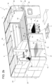
Figures 2a and2b are isometric views of the laser processing machine ofFigure 1 in two distinct work configurations, with parts removed for clarity; -
Figures 3a, 3b and 3c show a section view of the laser processing machine in the work configurations ofFigures 2a and2b and an intermediate configuration; -
Figure 4 shows an enlarged section view of the laser processing machine in the intermediate configuration, with parts removed for clarity; -
Figure 5 shows an enlarged isometric view of a portion of the processing machine ofFigure 1 , with parts removed for clarity; and -
Figure 6 shows a side view of a detail of the portion ofFigure 5 , with parts removed for clarity. - In
Figure 1 ,reference numeral 1 indicates, as a whole, a laser processing machine for treating, by means of a laser,work pieces 2 for obtaining processedpieces 3. - According to some non-limiting embodiments, the
machine 1 can be configured to carry out one or more of the following laser processing processes: cutting, engraving, boring, welding, cropping, butt joining, and other. - According to some non-limiting embodiments, the
work piece 2 can comprise, in particular consist of, a metal material such as for example steel, carbon steel, stainless steel, aluminium, brass, copper, titanium alloys and other alloys or any combination thereof. - The
work pieces 2 can have complex or simple structures. For example, thework pieces 2 can have respective (complex) three-dimensional structures or bi-dimensional structures. - The
work pieces 2 can be for example unfinished products, as possibly obtained by means of curvature, printing, hydroforming or other processes. - For example,
work pieces 2 can be curved pipes, formed sheets, other types or combinations thereof. - With reference to
Figures 1 to 4 , themachine 1 comprises: - a
housing 4, in particular having and/or delimiting aninner space 5; e - a
laser apparatus 6 arranged in thehousing 4, in particular in theinner space 5, for carrying out a laser processing onwork pieces 2. - In more detail, the
housing 4 extends along a first axis A, a second axis B perpendicular to the first axis A and a third axis C perpendicular to the first axis A and to the second axis B. In particular, the first axis A and the third axis C can have respective horizontal orientations and the second axis B can have a vertical orientation. - Preferentially, the extension of the
housing 4 along: - the first axis A can define a width of the
housing 4; - along the second axis B it can define a height of the
housing 4; and - along the third axis C it can define a depth of the
housing 4. - The
housing 4 comprises afirst work space 7 and asecond work space 8 distinct and separate from one another and each configured to receivework pieces 2. - The
housing 4 further comprises a dividingwall 9, in particular placed in theinner space 5, which separates thefirst work space 7 and thesecond work space 8 from one another. In other words, the dividingwall 9 is interposed between thefirst work space 7 and thesecond work space 8. - Furthermore, the
housing 4 comprises a coveringdevice 10, in particular placed in theinner space 5, configured to selectively cover at least one between thefirst work space 7 and thesecond work space 8. In particular, the coveringdevice 10 can be configured to cover one between thefirst work space 7 and thesecond work space 8 and to free the other between thefirst work space 7 and thesecond work space 8. - For example, in
Figures 2a and2b , the respective conditions in which the coveringdevice 10 covers thefirst work space 7 and thesecond work space 8, respectively, are indicated. - This allows carrying out a laser processing in the
work space device 10, while an operator can remove a processedpiece 3 and/or insert anew work piece 2 in theother work space 7 or 8 (i.e. thework space - In particular, the dividing
wall 9 can define a respective lateral wall of thefirst work space 7 and of thesecond work space 8. - Preferentially, the
dividing wall 9 extends vertically. - In more detail, the
dividing wall 9 extends along an axis parallel to the second axis B and another axis parallel to the third axis C. Preferentially, an extension of thedividing wall 9 along an axis parallel to the axis A can define a width of the dividingwall 9. - Furthermore, the
housing 4 can comprise two auxiliarylateral walls 15, each one being spaced from the dividingwall 9, in particular in a direction parallel to the first axis A. In particular, the dividingwall 9 can be interposed between the two auxiliarylateral walls 15 for partially delimiting thefirst work space 7 and thesecond work space 8. - More specifically, one of the auxiliary
lateral walls 15 can delimit, together with thedividing wall 9, an extension (i.e. the respective length) of thefirst work space 7 along an axis parallel to the first axis A and the other auxiliarylateral wall 15 can delimit, together with thedividing wall 9, an extension (i.e. the respective length) of thesecond work space 7 along an axis parallel to the first axis A. - Furthermore, the
housing 4 can also comprise a firstauxiliary wall 16 and a second auxiliary wall transverse to, and in particular being in contact with, the dividingwall 9. In particular, the firstauxiliary wall 16 and the second auxiliary wall are spaced apart from one another along a direction parallel to the third axis C and delimit thefirst work space 7 and thesecond work space 8 along the direction parallel to the third axis C. - Preferentially, the first
auxiliary wall 16 and the second auxiliary wall can face one another. - Preferentially, the first
auxiliary wall 16 can be placed in theinner space 5. - According to some preferred embodiments, the first
auxiliary wall 16 and the second auxiliary wall comprise respective first portions and respective second portions, in which the respective first portions and the respective second portions delimit thefirst work space 7 and thesecond work space 8, respectively, in a direction parallel to the third axis C. - In particular, each first portion and each second portion is interposed and/or extends between the dividing
wall 9 and a respective auxiliary lateral wall. - Preferentially, the
housing 4, in particular the second auxiliary wall, can comprise afirst entrance 17 and asecond entrance 18 configured to allow access, for example to an operator and/or to a robot, to thefirst work space 7 and to thesecond work space 8, respectively. - More specifically, the first portion and the second portion of the second auxiliary wall can comprise the
first entrance 17 and thesecond entrance 18, respectively. - In particular, the
housing 4 can comprise a closing device configured to selectively open and close thefirst entrance 17 and thesecond entrance 18. More specifically, the closing device can comprise one or more doors, in particular sliding doors, so as to selectively open and close thefirst entrance 17 and thesecond entrance 18. Still more specifically, the closing device can comprise afirst door 19, in particular a sliding door, configured to selectively open and close thefirst entrance 17 and asecond door 20, in particular a sliding door, configured to selectively open and close thesecond entrance 18. - Preferentially, the closing device can be configured to open the
first entrance 17 while, in use, the covering device covers thefirst work space 7 and/or the closing device can be configured to open thesecond entrance 18 while, in use, the covering device covers thesecond work space 8. - Furthermore, the closing device can be configured to close the
first entrance 17 while, in use, the covering device does not cover (opens) thefirst work space 7 and/or the closing device can be configured to close thesecond entrance 18 while, in use, the covering device does not cover (opens) thesecond work space 8. - Preferentially, in use, the closing device closes the
first entrance 17 while thelaser apparatus 6 carries out a laser processing in thefirst work space 7 and/or thesecond entrance 18 while thelaser apparatus 6 carries out a laser processing in thesecond space 8. - In further detail, the
housing 4 can comprise afront wall 21, a rear wall 22 facing, and spaced apart from, thefront wall 21, twolateral walls 23 spaced apart from one another and interposed between thefront wall 21 and the rear wall 22 and a coveringwall 24. - Preferentially, the
housing 4 can also comprise abase support 25 facing, and spaced apart from, the coveringwall 24. According to some non-limiting embodiments, thebase support 25 can be formed by a respective wall and/or by a portion of a plane of a production site. - More specifically, the dividing
wall 9, thefront wall 21, the rear wall 22, thelateral walls 23 extend from thebase support 25, in particular in a direction parallel to the second axis B, still more in particular vertically. - Preferentially, the
front wall 21 can comprise the second auxiliary wall, thefirst entrance 17 and thesecond entrance 18. In particular, a portion of thefront wall 21 can define the second auxiliary wall. - Preferentially, the
front wall 21 can also comprise one or more housing spaces for the closing device, in particular thefirst door 19 and thesecond door 20. - Preferentially, each
lateral wall 23 can comprise a respective auxiliarylateral wall 15. In other words, a portion of eachlateral wall 23 defines a respective auxiliarylateral wall 15. - Furthermore, the dividing
wall 9 can be transverse, in particular perpendicular, to thefront wall 21. - Additionally, the first
auxiliary wall 16 can be interposed between thefront wall 21 and the rear wall 22. - With particular reference to
Figures 1 to 6 , the dividingwall 9 comprises at least onefirst end portion 30 configured to be in contact and/or being in contact with a support surface, in particular of thebase support 25, and asecond end portion 31 opposite thefirst end portion 30, in particular along a direction parallel to the second axis B. - In particular, a distance between the
first end portion 30 and thesecond end portion 31 defines a main height of the dividingwall 9. - Preferentially, the
first end portion 30 can define a lower portion of the dividingwall 9 and thesecond end portion 31 can define an upper portion of the dividingwall 9. - In particular, the dividing
wall 9 extends from thefirst end portion 30 to thesecond end portion 31 towards the coveringwall 24 and/or along an axis parallel to the second axis B. - According to the illustrated embodiment, the dividing
wall 9 can also comprise a protrudingportion 26 protruding from thesecond end portion 31 towards the coveringwall 24. Preferentially, the protrudingportion 26 is in contact with the second auxiliary wall and/or thefront wall 21. - In particular, an extension of a portion of the
second end portion 31 not in contact with the protrudingportion 26 is at least five times, preferentially at least 10 times, greater than an extension of a portion of the second end portion from which the protrudingportion 26 extends. - The covering
device 10 comprises: - a
first cover 32 and asecond cover 33, each controllable at least in an active configuration in which thefirst cover 32 and thesecond cover 33 are configured to cover and/or cover thefirst work space 7 and thesecond work space 8, respectively; and - a
guide system 34 configured to guide thefirst cover 32 and thesecond cover 33 so that thefirst cover 32 and thesecond cover 33, when they are in the respective active configurations, comprise at least a respectivemain portion 35 and a respectiveauxiliary portion 36 extending from the respectivemain portion 35. - Alternatively, the covering
device 10 could comprise only a cover controllable in a first active configuration and a second active configuration. When such cover is in the first active configuration and in the second active configuration, the cover covers thefirst work space 7 and thesecond work space 8, respectively. Independently, when the cover is in the first active configuration and in the second active configuration, the cover comprises the respectivemain portion 35 and the respectiveauxiliary portion 36. - The
guide system 34 is configured so that, being thefirst cover 32 and thesecond cover 33 in the active configuration, the respectiveauxiliary portion 36 is transverse and/or inclined relative to the respectivemain portion 35 and extends from the respectivemain portion 35 towards and/or to the dividingwall 9, in particular towards and/or to thesecond end portion 31. - Preferentially, each
auxiliary portion 36 is not perpendicular to the respectivemain portion 35. - Preferentially, each
auxiliary portion 36 and the respectivemain portion 35 can define an obtuse angle. - In particular, being the
first cover 32 and thesecond cover 33 in the active configuration, the respectiveauxiliary portion 36 can be in contact with the dividingwall 9, in particular thesecond end portion 31. - Preferentially, the
guide system 34 can be configured so that, being thefirst cover 32 and thesecond cover 33 in the active configuration, the respectivemain portion 35 is arranged at a first height level, which is above a second height level of the dividingwall 9, in particular of thesecond end portion 31. - In other words, the
guide system 34 is configured so that, being thefirst cover 32 and thesecond cover 33 in the active configuration, the respectivemain portion 35 is arranged above the dividingwall 9, in particular of thesecond end portion 31. - In this manner, it is ensured that the respective
auxiliary portion 36 light-proof closes a connection between thefirst work space 7 and thesecond work space 8 in the area of the dividingwall 9, in particular of thesecond end portion 31. Furthermore, it is ensured that the respectivemain portion 35 together with the respectiveauxiliary portion 36 covers and light-proof closes thefirst work space 7 or thesecond work space 8. - It should be noted that the terms "to light-proof close", "light-proof closing", "light-proof closed" indicate that the closing is such that light rays can neither exit nor enter from or into the
first work space 7 andsecond work space 8 and through thefirst cover 32 and thesecond cover 33, respectively. - Preferentially, each
main portion 35 has a (substantially) horizontal orientation and/or eachmain portion 35 is (substantially) parallel to thebase support 25. - According to some non-limiting embodiments, each one of the
first cover 32 and thesecond cover 33 can be controllable in a respective waiting configuration in which thefirst cover 32 and thesecond cover 33 are configured to free and/or free thefirst work space 7 and thesecond work space 8, respectively. - In particular, the
housing 4 is configured so that one between thefirst cover 7 and thesecond cover 8 can be controlled in the respective active configuration while the other between thefirst cover 7 and thesecond cover 8 can be controlled in the waiting configuration. Furthermore, thehousing 4 can also be configured to control thefirst cover 7 and thesecond cover 8 simultaneously in the respective active configuration or in the respective waiting configuration. - In more detail, each one of the
first cover 32 and thesecond cover 33 can comprise a plurality of elongated elements, in particular along a longitudinal axis. In particular, the extension of the elongated elements along the longitudinal axis can define a length of the elongated elements. Still more in particular, the length of each elongated element can be greater than the respective thickness and of the respective width; it should be noted that the thickness and the width can be determined relative to respective axes perpendicular to one another. - According to some non-limiting embodiments, the elongated elements can be connected in a movable and/or flexible manner to one another. Preferentially, the elongated elements are hinged to one another. For example, the elongated elements can define a roller blind or a rolling shutter.
- According to some non-limiting embodiments, each elongated element can be made in the shape of a stick, a panel, a slat, a flat profile, a table or the like.
- Preferentially, the plurality of elongated elements are aligned with one another so as to define a blind cover when the respective
first cover 31 or the respectivesecond cover 32 is controlled in the respective active configuration. In other words, the plurality of elongated elements are aligned with one another so as to obtain a light-proof closed cover (the light cannot pass through the cover). - According to some non-limiting embodiments, the plurality of the elongated elements is at least partially windable.
- With particular reference to
Figures 5 and6 , theguide system 34 can comprise a first group oftracks 37 for guiding thefirst cover 32 so that thefirst cover 32, when it is in the active configuration, has at least the respectivemain portion 36 and the respectiveauxiliary portion 35; and - a second group of
tracks 38 for guiding thesecond cover 33 so that thesecond cover 33, when it is in the active configuration, has at least the respectivemain portion 35 and the respectiveauxiliary portion 36. - Alternatively and in case the
housing 4 comprises a single cover, theguide system 34 comprises a group oftracks 37 which allows selectively placing the cover on top of thefirst work space 7 or thesecond work space 8. - In more detail, each one of the first group of
tracks 37 and the second group oftracks 38 can comprise a respectivefirst track 39 and asecond track 40 spaced apart from one another along a respective axis E parallel to the third axis C. - Furthermore, each
first track 39 and eachsecond track 40 can comprise afirst portion 41 and/or asecond portion 42. - In particular, the
first portions 41 can be made and/or configured to support and/or define the respectivemain portion 35 and/or thesecond portions 42 can be configured to support and/or define the respectiveauxiliary portion 36. - Additionally, each
second portion 42 can be connected to and extends from the respectivefirst portion 41 to thesecond end portion 32. - In particular, each
second portion 42 can be inclined relative to the respectivefirst portion 41. - Preferentially, each
first portion 41 can extend along a longitudinal axis (substantially) parallel to the first axis A. Still more preferentially, eachfirst portion 41 can be oriented horizontally. - More specifically, each
first portion 41 can be (substantially) placed in the area of the first height level and/or the placing of eachfirst portion 41 can define the first height level. Furthermore, eachsecond portion 42 can (substantially) extend from the first height level to the second height level. - In particular, the
first portions 41, in particular also thesecond portions 42, can be arranged above the dividingwall 9 and/or thesecond end portion 32. - According to some non-limiting embodiments, the
housing 4 can also comprise afirst housing device 43 and asecond housing device 44 for housing thefirst cover 32 and thesecond cover 33, respectively, in particular when it is controlled in the respective waiting configuration. - Preferentially, the
first housing device 43 can be arranged in a first lateral area of thehousing 4, in particular of theinner space 5, and thesecond housing device 44 can be arranged in a second lateral area of thehousing 4, in particular of theinner space 5, opposite the second lateral area. - More specifically, the
first housing device 43 and thesecond housing device 44 can be spaced apart from one another along a direction parallel to the first axis A. - Furthermore, the
first housing device 43 and thesecond housing device 44 can be arranged above thefirst work space 7 and thesecond work space 8, respectively. - Alternatively, the
first housing device 43 and thesecond housing device 44 can be arranged at least partially or completely in thefirst work space 7 and in thesecond work space 8, respectively. - According to some non-limiting embodiments, the
housing 4 can also comprise anactuating device 45 configured to selectively control thefirst cover 32 and thesecond cover 33 between the active configuration and the waiting configuration. - In particular, the
actuating device 45 can be configured to control one between thefirst cover 32 and thesecond cover 33 in the active configuration and the other between thefirst cover 32 and thesecond cover 33 in the waiting configuration. - In more detail, the
actuating device 45 can comprise: - a
first actuator 46, in particular a first motor, operatively associated with thefirst cover 32 for controlling thefirst cover 32 between the respective active configuration and the respective waiting configuration; and - a
second actuator 47, in particular a second motor, operatively associated with thesecond cover 33 for controlling thesecond cover 33 between the respective active configuration and the respective waiting configuration. - In particular, in use, during the control of the
first cover 32 and of thesecond cover 33 from the waiting configuration to the active configuration, thefirst cover 32 and thesecond cover 33 respectively move from thefirst housing device 43 and from thesecond housing device 44, respectively, towards thesecond end portion 31 up to establishing the contact between the respectiveauxiliary portion 36 and thesecond end portion 31. - Furthermore, in use, during the control of the
first cover 32 and of thesecond cover 33 from the active configuration to the waiting configuration, thefirst cover 32 and thesecond cover 33 respectively move away from thesecond end portion 31 and towards and in thefirst housing device 43 and thesecond housing device 44, respectively. - With particular reference to
Figures 1 to 4 , thelaser apparatus 6 can comprise one or more laser devices, in the specific case alaser device 50 is illustrated. - The
laser apparatus 6 can also comprise asupport structure 51, in particular arranged in theinner space 5, carrying thelaser device 50 in a movable manner. - In more detail, the
support structure 51 can comprise a fixedstructure 52 and amovable structure 53 carrying thelaser device 50 and coupled in a movable manner to the fixedstructure 52. In particular, themovable structure 53 can be movable along a path, in particular a linear path. - Furthermore, the
support structure 51 can comprise an actuator for moving themovable structure 53 along the path. - In further detail, the
laser device 50 is coupled to themovable structure 53 so as to carry out respective angular movements around one or more rotation axes and a translation along a respective axis (substantially) parallel to the second axis B (for selectively approaching and spacing apart thelaser device 50 to or from the work piece 2). - The
movable structure 53 can allow selectively placing thelaser device 50 in thefirst work space 7 and in thesecond work space 8. - According to some non-limiting embodiments, the
laser processing machine 1 can also comprise two work tables 54, one arranged in thefirst work space 7 and the other in thesecond work space 8. Each work table 54 is configured to support the work pieces 2 (and then, the processed pieces 3) . - According to some preferred non-limiting embodiments, the
laser device 50 can be placed in a neutral area, in particular above the dividingwall 9. In particular, in use, while thelaser device 50 is in the neutral area, it is possible to simultaneously control thefirst cover 32 and thesecond cover 33 in the respective active configurations or in the respective waiting configurations. - The
laser processing machine 1 can further comprise a man-machine interface 55. - In use, the
processing machine 1 laser-processes work pieces 2 for obtaining processedpieces 3. - In particular, the
work pieces 2 are placed in thefirst work space 7 and in thesecond work space 8. - In order to carry out the processing, the
laser device 50 has to be placed in thefirst work space 7 or in thesecond work space 8. - For example (see
Figures 2b and3c ) thecovering device 10 covers thefirst work space 7, in particular by means of the control of the respectivefirst cover 32 in the active configuration, while thelaser apparatus 6, in particular thelaser device 50, carries out the laser processing of thework piece 2 placed in thesecond work space 8 while thesecond cover 33 is in the respective waiting configuration. Furthermore, the closing device, in particular thesecond door 20, closes thesecond entrance 18. Advantageously, during the laser processing of thework piece 2 present in thesecond work space 8, it is possible, for example through an operator or a robot, to remove a processedpiece 3 from thefirst work space 7 and/or to place anew work piece 2 in thefirst work space 7. - In the other example (see
Figures 2a and3a ), which can be carried out before or after the example ofFigures 2b and3c , the coveringdevice 10 covers thesecond work space 8, in particular by means of the control of the respectivesecond cover 33 in the active configuration, while thelaser apparatus 6, in particular thelaser device 50, carries out the laser processing of thework piece 2 placed in thefirst work space 7 while thefirst cover 32 is in the respective waiting configuration. In this case, the closing device, in particular thefirst door 19, closes thefirst entrance 18. According to this example, during the laser processing of thework piece 2 present in thefirst work space 7, it is possible, for example through an operator or a robot, to remove a processedpiece 3 from thesecond work space 8 and/or to place anew work piece 2 in thesecond work space 8. - In order to carry out at times the laser processing in the
first work space 7 and at times in thesecond work space 8 it is necessary to transfer thelaser device 50 from thefirst work space 7 or from thesecond work space 8 to thesecond work space 8 or to thefirst work space 7. For this reason, it is necessary to control thefirst cover 32 and thesecond cover 33 from the active configuration to the waiting configuration if the laser processing was carried out in thesecond work space 8 or in thefirst work space 7, respectively. - During or following the transfer of the
laser device 50 from thefirst work space 7 to thesecond work space 8 or vice versa, it is possible to control thefirst cover 32 or thesecond cover 33, respectively, from the waiting configuration to the active configuration. - It should be noted that it is also possible to control the
first cover 32 and thesecond cover 33 simultaneously in the respective active configuration or in the respective waiting configuration. Preferentially, also thefirst door 19 and thesecond door 20 are respectively controlled for opening and closing thefirst entrance 17 and thesecond entrance 18, respectively, when thefirst cover 32 and thesecond cover 33 are respectively controlled in the respective active configurations and in the respective waiting configurations. - For example (see for example
Figure 3b ), it is possible to control both thefirst cover 32 and thesecond cover 33 in the respective active configurations, while thelaser device 50 is placed in the neutral area. Preferentially, when thefirst cover 32 and thesecond cover 33 are simultaneously in the respective active configurations or in the respective waiting configurations, the closing device simultaneously opens and closes thefirst entrance 17 and thesecond entrance 19, respectively. - It should be noted that in this manner it is possible to carry out a processing first in one between the
first work space 7 and thesecond work space 8 and then in the other, while the processedpieces 3 are removed andnew work pieces 2 are loaded after the processing in thefirst work space 7 and in thesecond work space 8. - In more detail, during the control of the
first cover 32 and of thesecond cover 33 from the active configuration to the waiting configuration or from the waiting configuration to the active configuration, the first group oftracks 37 and the second group oftracks 38 guide the movement of thefirst cover 32 and of thesecond cover 33, respectively. - During the movement from the waiting configuration to the active configuration, the respective
main portions 35 and the respectiveauxiliary portions 36 are obtained. - By examining the characteristics of the
processing machine 1 and/or of thehousing 4 according to the present invention, the advantages that they allow obtaining are evident. - A first advantage lies in the fact that it is possible to place the
laser device 50 in the neutral area so that thelaser device 50 can be placed in thefirst work space 7 or in thesecond work space 8 depending on whether thefirst work space 7 or thesecond work space 8 is ready for first. - Another advantage lies in the fact that the
first cover 32 and thesecond cover 33 can be controlled independently of one another without creating an interference with thelaser device 50. - Another advantage lies in the fact that by means of the
closing device 10 it is possible to decrease the time necessary for placing thelaser device 50 from thefirst covering space 7 to thesecond covering space 8 or vice versa. This is possible because it is not necessary to operate a closing element which requires time, but only thefirst cover 32 and thesecond cover 33. Furthermore, it is not necessary to place thelaser device 50 relative to the opening freed by the closing element. - Another advantage lies in the fact of having removed the closing element which proved to be a component with a critical reliability.
- Furthermore, the closing element is a costly element and with its elimination a more cost-effective solution is obtained.
- Finally, it is clear that modifications and variations can be made to the described and
illustrated processing machine 1 and/orhousing 4, which do not depart from the scope of protection defined by the claims. - According to some alternative embodiments, each
auxiliary portion 36 is substantially perpendicular to themain portion 35. Furthermore, thefirst cover 32 or thesecond cover 33 can comprise a further portion connected to theauxiliary portion 36 and configured to extend towards and/or to the dividingwall 9.
Claims (12)
- A housing (4) for a laser processing machine (1) to treat, by means of a laser, work pieces (2), in particular metal work pieces;the housing (4) comprises:- a dividing wall (9), which separates a first work space (7) and a second work space (8); and- a covering device (10), which is configured to selectively cover at least one between the first work space (7) and the second work space (8);- wherein the first work space (7) and the second work space (8) are configured to receive the work pieces (2);wherein the covering device (10) comprises at least:- a cover (32; 33), which is controllable at least in an active configuration, in which the cover (32; 33) is configured to cover one between the first work space (7) and the second work space (8); and- a guide system (34), which is configured to guide the cover (32; 33) so that the cover (32; 33), when it is in the active configuration, comprises at least a main portion (35) and an auxiliary portion (36) extending from the main portion (35) ;characterized in that the auxiliary portion (36) is inclined relative to the main portion (35) and extends from the main portion (35) towards and/or to the dividing wall (9) .
- The housing according to claim 1, wherein the guide system (34) is configured so that the main portion (35) is arranged above the dividing wall (9).
- The housing according to claim 1 or 2, wherein the dividing wall (9) comprises at least a first end portion (30) configured to be in contact and/or being in contact with a support surface and a second end portion (31) opposite the first end portion (30);
wherein the guide system (34) is configured so that the main portion (35) is arranged above the second end portion (31) and/or the main portion (35) is arranged at a first height level, which is above a second height level of the second end portion (31). - The housing according to any one of the preceding claims, wherein the cover (32; 33) comprises a plurality of elongated elements, in particular connected to one another in a movable and/or flexible manner.
- The housing according to any one of the preceding claims, wherein the guide system (34) comprises at least one group of tracks (37; 38) configured to guide the cover (32; 33) ;wherein the dividing wall (9) extends from a first end portion (30) to a second end portion (31) along a first axis (B) ;wherein the dividing wall (9) extends also along a second axis (C), which is transverse, in particular perpendicular to the first axis (B);wherein the group of tracks (37; 38) comprises at least a first track (39) and a second track (40), which are spaced apart from one another along an axis, which is parallel to the second axis (C);wherein each one of the first track (39) and the second track (40) comprises a first portion (41) and a second portion (42);wherein the first portions (41) are configured to support and/or define the main portion (35) and the second portions (40) are configured to support and/or define the auxiliary portion (36);wherein each second portion (40) is connected to and extends from the respective first portion (39) to the second end portion (40).
- The housing according to any one of the preceding claims, wherein the covering device (10) comprises:- a first cover (32), which is configured to selectively cover the first work area (7) when it is in the respective active configuration; and- a second cover (33), which is configured to selectively cover the second work area (8) when it is in the respective active configuration;wherein the guide system (34) comprises:- a first group of tracks (37) to guide the first cover (32) so that the first cover (32), when it is in the active configuration, has at least the respective main portion (35) and the respective auxiliary portion (36); and- a second group of tracks (38) to guide the second cover (33) so that the second cover (33), when it is in the active configuration, has at least the respective main portion (35) and the respective auxiliary portion (36).
- The housing according to claim 6, wherein each one of the first cover (32) and the second cover (33) is controllable in a respective waiting configuration, in which the first cover (32) and the second cover (33) are configured to free the first work space (7) and the second work space (8), respectively.
- The housing according to claim 7 and further comprising a first housing device (43) and a second housing device (44) to house the first cover (32) and the second cover (33), respectively, when it is controlled in the respective waiting configuration;
in particular, the first housing device (43) is arranged in a first lateral area of the housing (4) and the second housing device (44) is arranged in a second lateral area of the housing (4) opposite the first lateral area. - The housing according to any one of the preceding claims and comprising:- a first entrance (17) to allow access to the first work space (7);- a second entrance (18) to allow access to the second work space (8); and- a closing device (19; 20), which is configured to selectively open and close the first entrance (17) and the second entrance (18);wherein the closing device (19; 20) is configured to open the first entrance (17) while, in use, the covering device (10) covers the first work space (7); and/orwherein the closing device (19; 20) is configured to open the second entrance (18) while, in use, the covering device (10) covers the second work space (8).
- A laser processing machine (1) to treat, by means of a laser, work pieces (2), in particular metal work pieces, comprising:- a housing (4) according to any one of the preceding claims; and- at least one laser apparatus (4), which is configured to carry out a laser processing in the first work space (7) and in the second work space (8).
- The laser processing machine according to claim 10, wherein the laser apparatus (4) is configured to carry out a laser processing in the first work space (7) and in the second work space (8) while the covering device (10) covers the second work space (8) and the first work space (7), respectively.
- The laser processing machine according to claim 10 or 11, wherein the laser apparatus (4) comprises at least one laser device (50), which can selectively be placed in the first work space (7) and in the second work space (8) in order to carry out a laser processing in the first work space (7) and in the second work space (8), respectively.
Applications Claiming Priority (1)
| Application Number | Priority Date | Filing Date | Title |
|---|---|---|---|
| IT102021000030638A IT202100030638A1 (en) | 2021-12-03 | 2021-12-03 | HOUSING FOR A LASER PROCESSING MACHINE AND LASER PROCESSING MACHINE HAVING A HOUSING |
Publications (3)
| Publication Number | Publication Date |
|---|---|
| EP4190479A1 EP4190479A1 (en) | 2023-06-07 |
| EP4190479C0 EP4190479C0 (en) | 2024-09-11 |
| EP4190479B1 true EP4190479B1 (en) | 2024-09-11 |
Family
ID=80449075
Family Applications (1)
| Application Number | Title | Priority Date | Filing Date |
|---|---|---|---|
| EP22210770.8A Active EP4190479B1 (en) | 2021-12-03 | 2022-12-01 | Housing for a laser processing machine and laser processing machine having a housing |
Country Status (10)
| Country | Link |
|---|---|
| US (1) | US20230173622A1 (en) |
| EP (1) | EP4190479B1 (en) |
| JP (1) | JP2023083236A (en) |
| KR (1) | KR20230084073A (en) |
| CN (1) | CN116213968A (en) |
| CA (1) | CA3182542A1 (en) |
| IT (1) | IT202100030638A1 (en) |
| MX (1) | MX2022015185A (en) |
| TW (1) | TW202327789A (en) |
| ZA (1) | ZA202213000B (en) |
Families Citing this family (3)
| Publication number | Priority date | Publication date | Assignee | Title |
|---|---|---|---|---|
| USD1084066S1 (en) * | 2022-05-19 | 2025-07-15 | Mitsubishi Electric Corporation | Laser processing machine |
| USD1115880S1 (en) * | 2024-02-27 | 2026-03-03 | Hk Co., Ltd. | Laser processing machine |
| CN121017786B (en) * | 2025-09-23 | 2026-04-21 | 江苏创驰智能制造有限公司 | Gantry type efficient laser composite welding machine |
Family Cites Families (2)
| Publication number | Priority date | Publication date | Assignee | Title |
|---|---|---|---|---|
| EP2851604A1 (en) * | 2013-09-16 | 2015-03-25 | Arno Arnold GmbH | Pivotable protective covering and protector covering assembly with a pivoting protective covering |
| ITUB20159554A1 (en) * | 2015-12-15 | 2017-06-15 | Prima Ind Spa | WORK CELL AND CENTER FOR LASER WORKINGS EQUIPPED WITH THAT CELL |
-
2021
- 2021-12-03 IT IT102021000030638A patent/IT202100030638A1/en unknown
-
2022
- 2022-11-22 CA CA3182542A patent/CA3182542A1/en active Pending
- 2022-11-23 TW TW111144845A patent/TW202327789A/en unknown
- 2022-11-28 JP JP2022189325A patent/JP2023083236A/en active Pending
- 2022-11-30 MX MX2022015185A patent/MX2022015185A/en unknown
- 2022-11-30 ZA ZA2022/13000A patent/ZA202213000B/en unknown
- 2022-12-01 EP EP22210770.8A patent/EP4190479B1/en active Active
- 2022-12-01 CN CN202211524464.3A patent/CN116213968A/en active Pending
- 2022-12-02 US US18/073,724 patent/US20230173622A1/en active Pending
- 2022-12-02 KR KR1020220166518A patent/KR20230084073A/en active Pending
Also Published As
| Publication number | Publication date |
|---|---|
| KR20230084073A (en) | 2023-06-12 |
| US20230173622A1 (en) | 2023-06-08 |
| CA3182542A1 (en) | 2023-06-03 |
| EP4190479A1 (en) | 2023-06-07 |
| IT202100030638A1 (en) | 2023-06-03 |
| TW202327789A (en) | 2023-07-16 |
| MX2022015185A (en) | 2023-06-05 |
| EP4190479C0 (en) | 2024-09-11 |
| CN116213968A (en) | 2023-06-06 |
| JP2023083236A (en) | 2023-06-15 |
| ZA202213000B (en) | 2023-11-29 |
Similar Documents
| Publication | Publication Date | Title |
|---|---|---|
| EP4190479A1 (en) | Housing for a laser processing machine and laser processing machine having a housing | |
| EP4190480B1 (en) | Housing for a laser processing machine and laser processing machine having a housing | |
| US9890573B2 (en) | Sliding door of machine tool | |
| JP5649762B1 (en) | Machine Tools | |
| US20180361522A1 (en) | Work cell and laser-machining centre equipped with such cell | |
| US5871312A (en) | Machine tool having a sliding door | |
| JP4701666B2 (en) | Machine Tools | |
| JP2015003370A (en) | Machine tool having scattering prevention cover | |
| EP3260228B1 (en) | Sawing machine and guiding device for a saw band or saw blade of a sawing machine | |
| JP4400008B2 (en) | Machine tool with loader | |
| KR950031373A (en) | Processing equipment | |
| DE202017107190U1 (en) | Laser processing machine for machining workpieces, with a work space and with a loading area | |
| JP6703382B2 (en) | Laser processing machine equipment having a portion configured as the lamella region of the laser protection wall | |
| DE102004048037A1 (en) | Machine center for processing of metal parts, comprising control panel integrated in sliding door | |
| KR100649547B1 (en) | Door opener of machine tool | |
| JP3995438B2 (en) | Tool magazine | |
| BR102022024408A2 (en) | HOUSING FOR LASER PROCESSING MACHINE AND LASER PROCESSING MACHINE HAVING A HOUSING | |
| BR102022024542A2 (en) | HOUSING FOR LASER PROCESSING MACHINE AND LASER PROCESSING MACHINE HAVING A HOUSING | |
| JP7768732B2 (en) | machine tools | |
| DE112013007528T5 (en) | machine tool | |
| EP4028687B1 (en) | Covering device for an apparatus for feeding bars to a machine tool | |
| JP2009083064A (en) | Machine tool equipped with operation panel | |
| JP2526397Y2 (en) | Machine tool splash guard | |
| EP3875234B1 (en) | Industrial processing machine comprising a safety system | |
| KR101671858B1 (en) | Door system for machining center |
Legal Events
| Date | Code | Title | Description |
|---|---|---|---|
| PUAI | Public reference made under article 153(3) epc to a published international application that has entered the european phase |
Free format text: ORIGINAL CODE: 0009012 |
|
| STAA | Information on the status of an ep patent application or granted ep patent |
Free format text: STATUS: THE APPLICATION HAS BEEN PUBLISHED |
|
| AK | Designated contracting states |
Kind code of ref document: A1 Designated state(s): AL AT BE BG CH CY CZ DE DK EE ES FI FR GB GR HR HU IE IS IT LI LT LU LV MC ME MK MT NL NO PL PT RO RS SE SI SK SM TR |
|
| STAA | Information on the status of an ep patent application or granted ep patent |
Free format text: STATUS: REQUEST FOR EXAMINATION WAS MADE |
|
| 17P | Request for examination filed |
Effective date: 20231207 |
|
| RBV | Designated contracting states (corrected) |
Designated state(s): AL AT BE BG CH CY CZ DE DK EE ES FI FR GB GR HR HU IE IS IT LI LT LU LV MC ME MK MT NL NO PL PT RO RS SE SI SK SM TR |
|
| REG | Reference to a national code |
Ref country code: DE Ref legal event code: R079 Free format text: PREVIOUS MAIN CLASS: B23K0026080000 Ipc: B23K0026700000 Ref document number: 602022006042 Country of ref document: DE |
|
| GRAP | Despatch of communication of intention to grant a patent |
Free format text: ORIGINAL CODE: EPIDOSNIGR1 |
|
| STAA | Information on the status of an ep patent application or granted ep patent |
Free format text: STATUS: GRANT OF PATENT IS INTENDED |
|
| RIC1 | Information provided on ipc code assigned before grant |
Ipc: B23K 37/02 20060101ALI20240321BHEP Ipc: B23K 26/70 20140101AFI20240321BHEP |
|
| INTG | Intention to grant announced |
Effective date: 20240409 |
|
| RIN1 | Information on inventor provided before grant (corrected) |
Inventor name: RAFFAELLI, DAVIDE Inventor name: CROSATO, ANDREA Inventor name: GEMIGNANI, ROBERTO Inventor name: COLOMBO, ANDREA Inventor name: RIVA, GIOVANNI Inventor name: CATTANEO, CORRADO |
|
| GRAS | Grant fee paid |
Free format text: ORIGINAL CODE: EPIDOSNIGR3 |
|
| GRAA | (expected) grant |
Free format text: ORIGINAL CODE: 0009210 |
|
| STAA | Information on the status of an ep patent application or granted ep patent |
Free format text: STATUS: THE PATENT HAS BEEN GRANTED |
|
| AK | Designated contracting states |
Kind code of ref document: B1 Designated state(s): AL AT BE BG CH CY CZ DE DK EE ES FI FR GB GR HR HU IE IS IT LI LT LU LV MC ME MK MT NL NO PL PT RO RS SE SI SK SM TR |
|
| REG | Reference to a national code |
Ref country code: GB Ref legal event code: FG4D |
|
| REG | Reference to a national code |
Ref country code: CH Ref legal event code: EP |
|
| REG | Reference to a national code |
Ref country code: DE Ref legal event code: R096 Ref document number: 602022006042 Country of ref document: DE |
|
| REG | Reference to a national code |
Ref country code: IE Ref legal event code: FG4D |
|
| U01 | Request for unitary effect filed |
Effective date: 20240917 |
|
| U07 | Unitary effect registered |
Designated state(s): AT BE BG DE DK EE FI FR IT LT LU LV MT NL PT RO SE SI Effective date: 20241009 |
|
| PG25 | Lapsed in a contracting state [announced via postgrant information from national office to epo] |
Ref country code: NO Free format text: LAPSE BECAUSE OF FAILURE TO SUBMIT A TRANSLATION OF THE DESCRIPTION OR TO PAY THE FEE WITHIN THE PRESCRIBED TIME-LIMIT Effective date: 20241211 |
|
| U20 | Renewal fee for the european patent with unitary effect paid |
Year of fee payment: 3 Effective date: 20241212 |
|
| PG25 | Lapsed in a contracting state [announced via postgrant information from national office to epo] |
Ref country code: GR Free format text: LAPSE BECAUSE OF FAILURE TO SUBMIT A TRANSLATION OF THE DESCRIPTION OR TO PAY THE FEE WITHIN THE PRESCRIBED TIME-LIMIT Effective date: 20241212 |
|
| PG25 | Lapsed in a contracting state [announced via postgrant information from national office to epo] |
Ref country code: HR Free format text: LAPSE BECAUSE OF FAILURE TO SUBMIT A TRANSLATION OF THE DESCRIPTION OR TO PAY THE FEE WITHIN THE PRESCRIBED TIME-LIMIT Effective date: 20240911 |
|
| PG25 | Lapsed in a contracting state [announced via postgrant information from national office to epo] |
Ref country code: RS Free format text: LAPSE BECAUSE OF FAILURE TO SUBMIT A TRANSLATION OF THE DESCRIPTION OR TO PAY THE FEE WITHIN THE PRESCRIBED TIME-LIMIT Effective date: 20241211 Ref country code: ES Free format text: LAPSE BECAUSE OF FAILURE TO SUBMIT A TRANSLATION OF THE DESCRIPTION OR TO PAY THE FEE WITHIN THE PRESCRIBED TIME-LIMIT Effective date: 20240911 |
|
| PG25 | Lapsed in a contracting state [announced via postgrant information from national office to epo] |
Ref country code: RS Free format text: LAPSE BECAUSE OF FAILURE TO SUBMIT A TRANSLATION OF THE DESCRIPTION OR TO PAY THE FEE WITHIN THE PRESCRIBED TIME-LIMIT Effective date: 20241211 Ref country code: NO Free format text: LAPSE BECAUSE OF FAILURE TO SUBMIT A TRANSLATION OF THE DESCRIPTION OR TO PAY THE FEE WITHIN THE PRESCRIBED TIME-LIMIT Effective date: 20241211 Ref country code: HR Free format text: LAPSE BECAUSE OF FAILURE TO SUBMIT A TRANSLATION OF THE DESCRIPTION OR TO PAY THE FEE WITHIN THE PRESCRIBED TIME-LIMIT Effective date: 20240911 Ref country code: GR Free format text: LAPSE BECAUSE OF FAILURE TO SUBMIT A TRANSLATION OF THE DESCRIPTION OR TO PAY THE FEE WITHIN THE PRESCRIBED TIME-LIMIT Effective date: 20241212 Ref country code: ES Free format text: LAPSE BECAUSE OF FAILURE TO SUBMIT A TRANSLATION OF THE DESCRIPTION OR TO PAY THE FEE WITHIN THE PRESCRIBED TIME-LIMIT Effective date: 20240911 |
|
| PG25 | Lapsed in a contracting state [announced via postgrant information from national office to epo] |
Ref country code: IS Free format text: LAPSE BECAUSE OF FAILURE TO SUBMIT A TRANSLATION OF THE DESCRIPTION OR TO PAY THE FEE WITHIN THE PRESCRIBED TIME-LIMIT Effective date: 20250111 |
|
| PG25 | Lapsed in a contracting state [announced via postgrant information from national office to epo] |
Ref country code: SM Free format text: LAPSE BECAUSE OF FAILURE TO SUBMIT A TRANSLATION OF THE DESCRIPTION OR TO PAY THE FEE WITHIN THE PRESCRIBED TIME-LIMIT Effective date: 20240911 |
|
| PG25 | Lapsed in a contracting state [announced via postgrant information from national office to epo] |
Ref country code: CZ Free format text: LAPSE BECAUSE OF FAILURE TO SUBMIT A TRANSLATION OF THE DESCRIPTION OR TO PAY THE FEE WITHIN THE PRESCRIBED TIME-LIMIT Effective date: 20240911 Ref country code: PL Free format text: LAPSE BECAUSE OF FAILURE TO SUBMIT A TRANSLATION OF THE DESCRIPTION OR TO PAY THE FEE WITHIN THE PRESCRIBED TIME-LIMIT Effective date: 20240911 |
|
| PG25 | Lapsed in a contracting state [announced via postgrant information from national office to epo] |
Ref country code: SK Free format text: LAPSE BECAUSE OF FAILURE TO SUBMIT A TRANSLATION OF THE DESCRIPTION OR TO PAY THE FEE WITHIN THE PRESCRIBED TIME-LIMIT Effective date: 20240911 |
|
| PG25 | Lapsed in a contracting state [announced via postgrant information from national office to epo] |
Ref country code: MC Free format text: LAPSE BECAUSE OF FAILURE TO SUBMIT A TRANSLATION OF THE DESCRIPTION OR TO PAY THE FEE WITHIN THE PRESCRIBED TIME-LIMIT Effective date: 20240911 |
|
| PLBE | No opposition filed within time limit |
Free format text: ORIGINAL CODE: 0009261 |
|
| STAA | Information on the status of an ep patent application or granted ep patent |
Free format text: STATUS: NO OPPOSITION FILED WITHIN TIME LIMIT |
|
| 26N | No opposition filed |
Effective date: 20250612 |
|
| PG25 | Lapsed in a contracting state [announced via postgrant information from national office to epo] |
Ref country code: IE Free format text: LAPSE BECAUSE OF NON-PAYMENT OF DUE FEES Effective date: 20241201 |
|
| U20 | Renewal fee for the european patent with unitary effect paid |
Year of fee payment: 4 Effective date: 20251028 |
|
| PG25 | Lapsed in a contracting state [announced via postgrant information from national office to epo] |
Ref country code: CY Free format text: LAPSE BECAUSE OF FAILURE TO SUBMIT A TRANSLATION OF THE DESCRIPTION OR TO PAY THE FEE WITHIN THE PRESCRIBED TIME-LIMIT; INVALID AB INITIO Effective date: 20221201 |