EP4190274A1 - Dental handpiece - Google Patents
Dental handpiece Download PDFInfo
- Publication number
- EP4190274A1 EP4190274A1 EP22181867.7A EP22181867A EP4190274A1 EP 4190274 A1 EP4190274 A1 EP 4190274A1 EP 22181867 A EP22181867 A EP 22181867A EP 4190274 A1 EP4190274 A1 EP 4190274A1
- Authority
- EP
- European Patent Office
- Prior art keywords
- hole
- pipe body
- pressure regulating
- pipe
- ball
- Prior art date
- Legal status (The legal status is an assumption and is not a legal conclusion. Google has not performed a legal analysis and makes no representation as to the accuracy of the status listed.)
- Granted
Links
Images





Classifications
-
- A—HUMAN NECESSITIES
- A61—MEDICAL OR VETERINARY SCIENCE; HYGIENE
- A61C—DENTISTRY; APPARATUS OR METHODS FOR ORAL OR DENTAL HYGIENE
- A61C1/00—Dental machines for boring or cutting ; General features of dental machines or apparatus, e.g. hand-piece design
- A61C1/02—Dental machines for boring or cutting ; General features of dental machines or apparatus, e.g. hand-piece design characterised by the drive of the dental tools
- A61C1/05—Dental machines for boring or cutting ; General features of dental machines or apparatus, e.g. hand-piece design characterised by the drive of the dental tools with turbine drive
-
- A—HUMAN NECESSITIES
- A61—MEDICAL OR VETERINARY SCIENCE; HYGIENE
- A61C—DENTISTRY; APPARATUS OR METHODS FOR ORAL OR DENTAL HYGIENE
- A61C1/00—Dental machines for boring or cutting ; General features of dental machines or apparatus, e.g. hand-piece design
- A61C1/0061—Air and water supply systems; Valves specially adapted therefor
-
- A—HUMAN NECESSITIES
- A61—MEDICAL OR VETERINARY SCIENCE; HYGIENE
- A61C—DENTISTRY; APPARATUS OR METHODS FOR ORAL OR DENTAL HYGIENE
- A61C1/00—Dental machines for boring or cutting ; General features of dental machines or apparatus, e.g. hand-piece design
- A61C1/0007—Control devices or systems
- A61C1/0038—Pneumatic systems
-
- A—HUMAN NECESSITIES
- A61—MEDICAL OR VETERINARY SCIENCE; HYGIENE
- A61C—DENTISTRY; APPARATUS OR METHODS FOR ORAL OR DENTAL HYGIENE
- A61C1/00—Dental machines for boring or cutting ; General features of dental machines or apparatus, e.g. hand-piece design
- A61C1/02—Dental machines for boring or cutting ; General features of dental machines or apparatus, e.g. hand-piece design characterised by the drive of the dental tools
- A61C1/05—Dental machines for boring or cutting ; General features of dental machines or apparatus, e.g. hand-piece design characterised by the drive of the dental tools with turbine drive
- A61C1/052—Ducts for supplying driving or cooling fluid, e.g. air, water
-
- A—HUMAN NECESSITIES
- A61—MEDICAL OR VETERINARY SCIENCE; HYGIENE
- A61C—DENTISTRY; APPARATUS OR METHODS FOR ORAL OR DENTAL HYGIENE
- A61C1/00—Dental machines for boring or cutting ; General features of dental machines or apparatus, e.g. hand-piece design
- A61C1/08—Machine parts specially adapted for dentistry
-
- A—HUMAN NECESSITIES
- A61—MEDICAL OR VETERINARY SCIENCE; HYGIENE
- A61C—DENTISTRY; APPARATUS OR METHODS FOR ORAL OR DENTAL HYGIENE
- A61C1/00—Dental machines for boring or cutting ; General features of dental machines or apparatus, e.g. hand-piece design
- A61C1/08—Machine parts specially adapted for dentistry
- A61C1/12—Angle hand-pieces
-
- A—HUMAN NECESSITIES
- A61—MEDICAL OR VETERINARY SCIENCE; HYGIENE
- A61C—DENTISTRY; APPARATUS OR METHODS FOR ORAL OR DENTAL HYGIENE
- A61C1/00—Dental machines for boring or cutting ; General features of dental machines or apparatus, e.g. hand-piece design
- A61C1/08—Machine parts specially adapted for dentistry
- A61C1/14—Tool-holders, i.e. operating tool holders, e.g. burr holders
- A61C1/141—Tool-holders, i.e. operating tool holders, e.g. burr holders in an angled handpiece
Definitions
- the present invention relates to a dental handpiece.
- Patent Literatures 1 and 2 disclose that a dental handpiece provided with a rotation mechanism such as an air turbine or an air motor driven to rotate by compressed air includes a pressure regulating mechanism that regulates a pressure of the compressed air to an appropriate range in order to reduce occurrences of damage to a dental treatment tool due to a high rotation speed of the rotation mechanism and wear due to a shortage of a lubricating oil.
- a pressure regulating mechanism includes a cylindrical piston 1, an air supply pipe 3 is disposed inside the piston 1, and a case 5 is disposed outside the piston 1.
- the piston 1 is axially slidable between the air supply pipe 3 and the case 5, and is biased to one side in an axial direction by a coil spring 7 accommodated in the case 5.
- a pressure of compressed air is applied to an end surface of the piston 1 opposite to the coil spring 7 and the pressure becomes larger than an urging force of the coil spring 7, the piston 1 slides to the other side in the axial direction against the urging force of the coil spring 7.
- Components such as the piston 1, the air supply pipe 3, and the case 5 constituting the pressure regulating mechanism described above are required to be processed with high accuracy such that a gap between the components is 10 ⁇ m or smaller, for example, in order to reduce a leakage of air. Therefore, a manufacturing cost increases.
- the structure since the structure has the cylindrical piston 1 slidable in the axial direction, an entire length may become long. Therefore, a large accommodation space may be required, which leads to an increase in a size of the entire handpiece.
- An object of the present invention is to provide a dental handpiece that efficiently utilizes supply air energy and is miniaturized while reducing a manufacturing cost.
- a dental handpiece includes: a head portion including a bar sleeve that is configured to detachably hold a dental treatment tool, and a rotation mechanism that is configured to rotate the bar sleeve by compressed air; and a tubular gripping portion including a front end provided on which the head portion is disposed and an air supply pipe that is configuted to supply the compressed air to the rotation mechanism.
- the air supply pipe includes a pressure regulating portion that regulates a pressure of the compressed air in the air supply pipe, and the pressure regulating portion includes: a pipe body through which the compressed air passes; a hole penetrating a pipe wall of the pipe body; a ball accommodated in the hole to close the hole; and an annular elastic member that is fitted to the pipe body and urges the ball from an outer peripheral side of the pipe body.
- supply air energy is efficiently utilized and a size is reduced while reducing a manufacturing cost.
- Fig. 1 is a side view of a gripping portion 11 of a dental handpiece 100 according to the present invention as viewed in a cross section along an axial direction.
- the dental handpiece 100 includes a gripping portion 11 and a head portion 13.
- the head portion 13 is provided at a front end of the gripping portion 11, and a dental treatment tool 15 is attached to the head portion 13.
- the dental handpiece 100 according to the present embodiment is an air turbine type handpiece in which the dental treatment tool 15 is rotated by compressed air.
- the gripping portion 11 includes a case 12 formed in a cylindrical shape, and an air supply pipe 17 and a water supply pipe 19 are provided inside the case 12.
- the air supply pipe 17 includes a pressure regulating mechanism 21 on a rear end side thereof.
- the water supply pipe 19 includes a check valve 23 on a rear end side thereof.
- An internal space of the case 12 of the gripping portion 11 serves as an exhaust flow path 25.
- a rear end of the gripping portion 11 serves as a connection portion 27, and a coupling member (not shown) is connected to the connection portion 27.
- a flexible tube (not shown) extending from a dental unit (not shown) that supplies compressed air and water is connected to the coupling member.
- Compressed air supplied from the dental unit is supplied to the air supply pipe 17 of the gripping portion 11.
- the compressed air supplied to the air supply pipe 17 passes through the pressure regulating mechanism 21 and is supplied toward the head portion 13.
- Water supplied from the dental unit is supplied to the water supply pipe 19 of the gripping portion 11.
- the water supplied to the water supply pipe 19 passes through the check valve 23 and is supplied toward the head portion 13. In the water supply pipe 19, backflow of water is reduced by the check valve 23.
- Fig. 2 is a cross-sectional view of the head portion 13 of the dental handpiece 100.
- the head portion 13 includes a head housing 33 that accommodates a rotation mechanism 31 therein.
- the rotation mechanism 31 includes a bar sleeve 35, a rotor 37, a pair of ball bearings 39, and a cartridge case 41.
- the bar sleeve 35 detachably holds the rod-shaped dental treatment tool 15, and the rotor 37 is provided on an outer periphery of the bar sleeve 35.
- the pair of ball bearings 39 are provided in the cartridge case 41. Both end portions of the bar sleeve 35 are rotatably supported by the ball bearings 39.
- the compressed air supplied from the air supply pipe 17 is blown to the rotor 37.
- the bar sleeve 35 holding the dental treatment tool 15 is rotated.
- the compressed air blown to the rotor 37 is discharged from the head portion 13 to the exhaust flow path 25 formed by the internal space of the case 12 of the gripping portion 11.
- a discharge port 43 communicating with the water supply pipe 19 is provided in a portion of the gripping portion 11 in vicinity of the head portion 13, and the water supplied from the water supply pipe 19 is discharged from the discharge port 43.
- An ejection port 47 communicating with a branch passage 45 branched from the air supply pipe 17 is provided at a position adjacent to the discharge port 43, and the compressed air supplied from the branch passage 45 is ejected from the ejection port 47.
- Fig. 3 is a cross-sectional view along the axial direction in vicinity of the rear end of the gripping portion 11 of the dental handpiece 100.
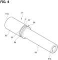
- Fig. 4 is a perspective view of the pressure regulating mechanism 21.
- Fig. 5 is a cross-sectional view of the pressure regulating mechanism 21 taken along the axial direction.
- the pressure regulating mechanism 21 provided in the air supply pipe 17 includes a pipe body 51 having a pressure regulating portion 50.
- the pressure regulating portion 50 of the pipe body 51 includes balls 53 and an annular elastic member 55.
- the pipe body 51 is formed in a tubular shape including a flow path 57.
- the pipe body 51 includes one end portion 51a to which the air supply pipe 17 is connected, and the other end portion 51b to which a connection portion (not shown) of an end portion of the flexible tube extending from the dental unit that supplies compressed air is connected.
- the other end portion 51b of the pipe body 51 is held by an adapter 28 constituting the connection portion 27 of the gripping portion 11.
- the pipe body 51 includes a fitting hole 59 having an inner diameter larger than that of the flow path 57 on one end portion 51a side, and an end portion of the air supply pipe 17 is fitted and connected to the fitting hole 59.
- An O-ring 61 is provided in the fitting hole 59, and a gap between the fitting hole 59 and the air supply pipe 17 is sealed by the O-ring 61.
- the pipe body 51 includes a large diameter portion 63 on the one end portion 51a side and a small diameter portion 65 formed to have a diameter smaller than that of the large diameter portion 63 on the other end portion 51b side.
- the pipe body 51 is provided with the pressure regulating portion 50 at a position of the large diameter portion 63 in vicinity of the small diameter portion 65 side.
- the pressure regulating portion 50 includes a plurality of holes 67 penetrating a pipe wall of the pipe body 51 from front to back surfaces.
- the pipe body 51 includes three holes 67, and these holes 67 are formed at equal intervals in a circumferential direction.
- the balls 53 are accommodated in the holes 67, respectively.
- a groove 69 is formed in an outer periphery of the large diameter portion 63 of the pressure regulating portion 50 of the pipe body 51.
- the groove 69 is formed in the circumferential direction at a position passing through positions where the holes 67 are formed.
- the groove 69 has a width smaller than a diameter of the ball 53 accommodated in the hole 67.
- the annular elastic member 55 is made of, for example, an elastic material such as rubber, and is formed in an annular shape.
- the annular elastic member 55 is formed in a circular shape in cross section.
- an O-ring may be used as the annular elastic member 55.
- the annular elastic member 55 is fitted to an outer periphery of the pipe body 51, and is accommodated in the groove 69 formed in the large diameter portion 63.
- the annular elastic member 55 fitted to the outer periphery of the pipe body 51 and accommodated in the groove 69 is accommodated in the groove 69 without protruding from an outer peripheral surface of the pipe body 51, and positional deviation in an axial direction of the pipe body 51 is reduced.
- a clearance C is formed between the annular elastic member 55 accommodated in the groove 69 and an inner peripheral surface of the hole 67 at a position on the outer periphery of pipe body 51 where the hole 67 is formed.
- Fig. 6 is a cross-sectional view taken along a line VI-VI in Fig. 5 .
- the hole 67 formed in the pressure regulating portion 50 of the pipe body 51 includes a small diameter hole 67a having an inner diameter smaller than a diameter of the ball 53 on an inner peripheral side of the pipe body 51.
- the ball 53 is accommodated in the hole 67 from an outer peripheral side of the pipe body 51.
- the ball 53 accommodated in the hole 67 is locked to the small diameter hole 67a on the inner peripheral side of the pipe body 51 in the hole 67, and movement of the pipe body 51 to the inner peripheral side is restricted.
- each hole 67 is urged toward the inner peripheral side of the pipe body 51 by an elastic force of the annular elastic member 55 fitted to the outer periphery of the pipe body 51 and accommodated in the groove 69. Thereby, the ball 53 accommodated in each hole 67 is brought into a state of abutting against an edge portion of the small diameter hole 67a of the hole 67, and each hole 67 is maintained in a state of being closed by the ball 53.
- the dental handpiece 100 including the pressure regulating mechanism 21 having the above-described structure, compressed air is supplied from the dental unit through the flexible tube connected by the coupling member.
- the supplied compressed air passes through the pipe body 51 constituting the pressure regulating mechanism 21 and is supplied to the air supply pipe 17.
- the compressed air is blown from the air supply pipe 17 to the rotor 37, and the bar sleeve 35 holding the dental treatment tool 15 is rotated.
- the compressed air blown to the rotor 37 is discharged from the head portion 13 to the exhaust flow path 25 formed by the internal space of the case 12 of the gripping portion 11, and is discharged to a dental unit side through an exhaust path of the flexible tube.
- the compressed air may be supplied from the dental unit at a pressure exceeding an appropriate range.
- the pressure regulating mechanism 21 as an internal pressure of the air supply pipe 17 increases, the ball 53 accommodated in each hole 67 of the pressure regulating portion 50 of the pipe body 51 is displaced outward in a radial direction of the pipe body 51 against a urging force of the annular elastic member 55. Then, each of the balls 53 is separated from the edge portion of the small diameter hole 67a of the hole 67, the compressed air in the pipe body 51 flows out from a gap between the hole 67 and the ball 53 to the exhaust flow path 25 on the outer peripheral side of the pipe body 51, and the internal pressure of the air supply pipe 17 is maintained in an appropriate range.
- the dental handpiece 100 of the present embodiment since a pressure of the supplied compressed air is maintained in the appropriate range by the pressure regulating part 50 of the pressure regulating mechanism 21 provided in the air supply pipe 17, in the rotation mechanism 31, occurrences of damage to the dental treatment tool 15 due to a high rotation speed of the bar sleeve 35 and wear due to a shortage of a lubricating oil are avoided.
- the pressure regulating portion 50 of the pressure regulating mechanism 21 has a structure in which the ball 53 is accommodated in the hole 67 formed in the pipe body 51, and the ball 53 is biased from the outer peripheral side by the annular elastic member 55 fitted to the pipe body 51. Therefore, the number of components is be reduced and a cost of the component itself is reduced as compared with a pressure regulating mechanism having a related-art structure in which compressed air is regulated by a piston slidable in an axial direction.
- a length in the axial direction may be shortened to reduce a size, and accommodating is easily performed in a narrow space in the gripping portion 11.
- the pressure regulating portion 50 is provided in the pipe body 51 separate from the air supply pipe 17, but the pressure regulating mechanism 21 may be configured by providing the pressure regulating portion 50 in a pipe body formed of the air supply pipe 17. According to this structure, the number of components is further reduced.
- Fig. 7 is a perspective view of a pressure regulating mechanism 21A according to a first modification.
- Fig. 8 is a cross-sectional view of the pressure regulating mechanism 21A according to the first modification, taken along an axial direction.
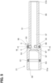
- Fig. 9 is a cross-sectional view taken along a line IX-IX in Fig. 8 .
- the pressure regulating mechanism 21A according to the first modification includes a pipe body 71 including two pressure regulating portions 50A.
- the pipe body 71 is formed in a tubular shape including a flow path 77.
- the pipe body 71 includes one end portion 71a to which the air supply pipe 17 is connected, and the other end portion 71b to which a connection portion of a flexible tube extending from a dental unit that supplies compressed air is connected.
- the pipe body 71 includes a fitting hole 79 in which the O-ring 61 is provided on one end portion 71a side, and an end portion of the air supply pipe 17 is fitted and connected to the fitting hole 79.
- the flow path 77 of the pipe body 71 includes a small diameter flow path portion 77a on a fitting hole 79 side.
- the pipe body 71 includes an intermediate diameter portion 73 on the one end portion 71a side, and a small diameter portion 75 formed to have a diameter smaller than that of the intermediate diameter portion 73 on the other end portion 71b side.
- an intermediate portion of the intermediate diameter portion 73 in the axial direction is formed as a large diameter portion 74 having a larger diameter.
- the two pressure regulating portions 50A are provided in the large diameter portion 74 of the pipe body 71, and are disposed at an interval in the axial direction.
- a relief portion 74a for avoiding interference with the water supply pipe 19 is formed in a portion of the large diameter portion 74 of the pipe body 71 at a water supply pipe 19 side.
- the pressure regulating portion 50A includes one hole 67 that accommodates the ball 53, and a groove 69 having a width smaller than a diameter of the ball 53 is formed at a position passing through a position where the one hole 67 is formed.
- the annular elastic member 55 is accommodated in the groove 69.
- the hole 67 formed in the pipe body 71 includes a small diameter hole 67a on an inner peripheral side of the pipe body 71, and further includes a large diameter hole 67b on an outer peripheral side of the pipe body 71.
- the ball 53 accommodated in the hole 67 from the outer peripheral side of the pipe body 71 is locked to the small diameter hole 67a on the inner peripheral side of the pipe body 71 in the hole 67, and movement of the pipe body 71 to the inner peripheral side is restricted.
- the ball 53 is urged by an elastic force of the annular elastic member 55 to abut against an edge portion of the small diameter hole 67a of the hole 67, whereby the hole 67 is maintained in a state of being closed by the ball 53.
- the ball 53 accommodated in the hole 67 of each pressure regulating portion 50A of the pressure regulating mechanism 21A is displaced outward in a radial direction of the pipe body 71 against an urging force of the annular elastic member 55.
- the ball 53 is separated from the edge portion of the small diameter hole 67a of the hole 67, and the compressed air in the pipe body 71 flows out from a gap between the hole 67 and the ball 53 to the exhaust flow path 25 on the outer peripheral side of the pipe body 71.
- Each pressure regulating portion 50A regulates a pressure in the one hole 67 that accommodates the ball 53. Therefore, the large diameter hole 67b is formed on the outer peripheral side of the pipe body 71 in the hole 67, and air is easily discharged at the time of pressure regulation.
- a material of the annular elastic member 55 may be selected to adjust the elastic force, so that the air can be easily released at the time of pressure regulation.
- the ball 53 biased by the annular elastic member 55 is accommodated in the one hole 67 of each pressure regulating portion 50A, so that a structure is simplified.
- the plurality of pressure regulating portions 50A are provided at the interval in the axial direction of the pipe body 71, redundancy is provided in a pressure regulating function, and safety is enhanced.
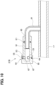
- Fig. 10 is a cross-sectional view of a pressure regulating mechanism 21B according to a second modification, taken along an axial direction.
- the pressure regulating mechanism 21B is attached to a branch pipe 81 provided in the air supply pipe 17.
- One end of the branch pipe 81 is connected to the air supply pipe 17, and an intermediate portion thereof is bent and extends along the air supply pipe 17.
- the pressure regulating mechanism 21B is connected to the other end of the branch pipe 81.
- the pressure regulating mechanism 21B includes a pipe body 91, and the pressure regulating portion 50 is provided in the pipe body 91.
- the pipe body 91 is formed in a bottomed tubular shape.
- the pipe body 91 includes a fitting hole 93 provided with the O-ring 61, and an end portion of the branch pipe 81 branched from the air supply pipe 17 is fitted and connected to the fitting hole 93.
- the pipe body 91 includes a large diameter portion 95 on an end portion side opposite to a connection side with the branch pipe 81, and the large diameter portion 95 is provided with the pressure regulating portion 50 in which the balls 53 are accommodated in three holes 67 and the balls 53 are biased by the annular elastic member 55.
- each ball 53 is separated from the edge portion of the small diameter hole 67a of the hole 67, the compressed air in the pipe body 91 flows out from a gap between the hole 67 and the ball 53 to the exhaust flow path 25 on an outer peripheral side of the pipe body 91, and an internal pressure of the air supply pipe 17 is maintained in an appropriate range.
- a supply path of the compressed air may be shortened, and an entire length of the dental handpiece 100 may be further shortened.
- the pressure regulating portion 50 may be provided in a branch pipe that branches off from the air supply pipe 17 and further joins the air supply pipe 17.
- the compressed air branched from the air supply pipe 17 to the branch pipe passes through the pressure regulating portion 50 of the branch pipe and joins the air supply pipe 17.
- the present invention is not limited to the above-described embodiment, and combinations of the configurations of the embodiment and modifications and applications by those skilled in the art based on the description of the specification and well-known techniques are also intended to be made by the present invention and are included in the scope required for protection.
- the pressure regulating portion has a structure in which the ball is accommodated in the hole formed in the pipe body, and the ball is biased from the outer peripheral side by the annular elastic member fitted to the pipe body. Therefore, the number of components isreduced and a cost of the component itself is reduced as compared with a pressure regulating mechanism having a related-art structure in which compressed air is regulated by a piston slidable in an axial direction.
- a length in the axial direction may be shortened to reduce a size, and accommodating is easily performed in a narrow space in the gripping portion.
- the supply air energy is efficiently utilized and the dental handpiece is miniaturized while reducing a manufacturing cost.
- a pressure regulating function is easily provided to the air supply pipe by the pressure regulating portion of the pressure regulating mechanism connected to the air supply pipe.
- the balls are accommodated in the plurality of holes formed at intervals in the circumferential direction, and the balls are pressed from the outer peripheral side of the pipe body by the annular elastic member. Therefore, when the pressure of the compressed air exceeds the appropriate range, the balls in the holes are displaced, and the pressure of the compressed air may be rapidly reduced.
- the ball accommodated in the hole is locked by the small diameter hole, so that the ball is arranged at an appropriate position of the hole.
- a clearance is formed between the annular elastic member accommodated in the groove and an inner peripheral surface of the hole at a position on the outer periphery of the pipe body where the hole is formed. Thereby, the compressed air is smoothly discharged from the clearance.
- the plurality of pressure regulating portions are provided at intervals in the axial direction of the pipe body, redundancy is provided in the pressure regulating function, and safety is enhanced.
- a supply path of the compressed air may be shortened, and an entire length of the dental handpiece may be shortened.
Landscapes
- Health & Medical Sciences (AREA)
- Oral & Maxillofacial Surgery (AREA)
- Dentistry (AREA)
- Epidemiology (AREA)
- Life Sciences & Earth Sciences (AREA)
- Animal Behavior & Ethology (AREA)
- General Health & Medical Sciences (AREA)
- Public Health (AREA)
- Veterinary Medicine (AREA)
- Engineering & Computer Science (AREA)
- Water Supply & Treatment (AREA)
- Dental Tools And Instruments Or Auxiliary Dental Instruments (AREA)
Abstract
Description
- The present invention relates to a dental handpiece.
-
Patent Literatures 1 and 2 disclose that a dental handpiece provided with a rotation mechanism such as an air turbine or an air motor driven to rotate by compressed air includes a pressure regulating mechanism that regulates a pressure of the compressed air to an appropriate range in order to reduce occurrences of damage to a dental treatment tool due to a high rotation speed of the rotation mechanism and wear due to a shortage of a lubricating oil. - As shown in
Fig. 11 , a pressure regulating mechanism includes acylindrical piston 1, anair supply pipe 3 is disposed inside thepiston 1, and acase 5 is disposed outside thepiston 1. Thepiston 1 is axially slidable between theair supply pipe 3 and thecase 5, and is biased to one side in an axial direction by acoil spring 7 accommodated in thecase 5. In this pressure regulating mechanism, when a pressure of compressed air is applied to an end surface of thepiston 1 opposite to thecoil spring 7 and the pressure becomes larger than an urging force of thecoil spring 7, thepiston 1 slides to the other side in the axial direction against the urging force of thecoil spring 7. Then, ahole 5a formed in thecase 5, which is normally closed by thepiston 1, communicates with ahole 3a formed in theair supply pipe 3, and the compressed air supplied into theair supply pipe 3 passes through theholes case 5 to regulate the pressure. -
- Patent Literature 1:
Japanese Patent No. 4147231 - Patent Literature 2:
Chinese Patent Application Publication No. 106491217 - Components such as the
piston 1, theair supply pipe 3, and thecase 5 constituting the pressure regulating mechanism described above are required to be processed with high accuracy such that a gap between the components is 10 µm or smaller, for example, in order to reduce a leakage of air. Therefore, a manufacturing cost increases. - Even if the components are processed with high accuracy, it is difficult to completely stop the leakage of air from the gap between the components. As a result, energy loss of the compressed air may occur and lead to a decrease in torque or rotational speed in a rotation mechanism.
- In addition, since the structure has the
cylindrical piston 1 slidable in the axial direction, an entire length may become long. Therefore, a large accommodation space may be required, which leads to an increase in a size of the entire handpiece. - An object of the present invention is to provide a dental handpiece that efficiently utilizes supply air energy and is miniaturized while reducing a manufacturing cost.
- According to an aspect of the disclosure, a dental handpiece includes: a head portion including a bar sleeve that is configured to detachably hold a dental treatment tool, and a rotation mechanism that is configured to rotate the bar sleeve by compressed air; and a tubular gripping portion including a front end provided on which the head portion is disposed and an air supply pipe that is configuted to supply the compressed air to the rotation mechanism.
- The air supply pipe includes a pressure regulating portion that regulates a pressure of the compressed air in the air supply pipe, and the pressure regulating portion includes: a pipe body through which the compressed air passes; a hole penetrating a pipe wall of the pipe body; a ball accommodated in the hole to close the hole; and an annular elastic member that is fitted to the pipe body and urges the ball from an outer peripheral side of the pipe body.
- According to the present disclosure, supply air energy is efficiently utilized and a size is reduced while reducing a manufacturing cost.
-
-
Fig. 1 is a side view of a gripping portion of a dental handpiece according to the present invention as viewed in a cross section along an axial direction. -
Fig. 2 is a cross-sectional view of a head portion of the dental handpiece. -
Fig. 3 is a cross-sectional view along the axial direction in vicinity of a rear end of the gripping portion of the dental handpiece. -
Fig. 4 is a perspective view of a pressure regulating mechanism. -
Fig. 5 is a cross-sectional view of the pressure regulating mechanism taken along the axial direction. -
Fig. 6 is a cross-sectional view taken along a line VI-VI inFig. 5 . -
Fig. 7 is a perspective view of a pressure regulating mechanism according to a first modification. -
Fig. 8 is a cross-sectional view of the pressure regulating mechanism according to the first modification, taken along an axial direction. -
Fig. 9 is a cross-sectional view taken along a line IX-IX inFig. 8 . -
Fig. 10 is a cross-sectional view of a pressure regulating mechanism according to a second modification, taken along an axial direction. -
Fig. 11 is a cross-sectional view along an axial direction in vicinity of a rear end of a gripping portion of a dental handpiece, showing a related-art pressure regulating mechanism. - Hereinafter, an embodiment of the present invention will be described in detail with reference to the drawings.
-
Fig. 1 is a side view of a grippingportion 11 of adental handpiece 100 according to the present invention as viewed in a cross section along an axial direction. - As shown in
Fig. 1 , thedental handpiece 100 according to the present embodiment includes agripping portion 11 and ahead portion 13. Thehead portion 13 is provided at a front end of the grippingportion 11, and adental treatment tool 15 is attached to thehead portion 13. Thedental handpiece 100 according to the present embodiment is an air turbine type handpiece in which thedental treatment tool 15 is rotated by compressed air. - The gripping
portion 11 includes acase 12 formed in a cylindrical shape, and anair supply pipe 17 and awater supply pipe 19 are provided inside thecase 12. Theair supply pipe 17 includes apressure regulating mechanism 21 on a rear end side thereof. Thewater supply pipe 19 includes acheck valve 23 on a rear end side thereof. An internal space of thecase 12 of the grippingportion 11 serves as anexhaust flow path 25. - A rear end of the
gripping portion 11 serves as aconnection portion 27, and a coupling member (not shown) is connected to theconnection portion 27. A flexible tube (not shown) extending from a dental unit (not shown) that supplies compressed air and water is connected to the coupling member. Compressed air supplied from the dental unit is supplied to theair supply pipe 17 of thegripping portion 11. The compressed air supplied to theair supply pipe 17 passes through thepressure regulating mechanism 21 and is supplied toward thehead portion 13. Water supplied from the dental unit is supplied to thewater supply pipe 19 of thegripping portion 11. The water supplied to thewater supply pipe 19 passes through thecheck valve 23 and is supplied toward thehead portion 13. In thewater supply pipe 19, backflow of water is reduced by thecheck valve 23. -
Fig. 2 is a cross-sectional view of thehead portion 13 of thedental handpiece 100. - As shown in
Fig. 2 , thehead portion 13 includes ahead housing 33 that accommodates arotation mechanism 31 therein. Therotation mechanism 31 includes abar sleeve 35, arotor 37, a pair ofball bearings 39, and acartridge case 41. - The
bar sleeve 35 detachably holds the rod-shapeddental treatment tool 15, and therotor 37 is provided on an outer periphery of thebar sleeve 35. The pair ofball bearings 39 are provided in thecartridge case 41. Both end portions of thebar sleeve 35 are rotatably supported by theball bearings 39. - In the
head portion 13, the compressed air supplied from theair supply pipe 17 is blown to therotor 37. Thereby, thebar sleeve 35 holding thedental treatment tool 15 is rotated. The compressed air blown to therotor 37 is discharged from thehead portion 13 to theexhaust flow path 25 formed by the internal space of thecase 12 of thegripping portion 11. - A
discharge port 43 communicating with thewater supply pipe 19 is provided in a portion of thegripping portion 11 in vicinity of thehead portion 13, and the water supplied from thewater supply pipe 19 is discharged from thedischarge port 43. Anejection port 47 communicating with abranch passage 45 branched from theair supply pipe 17 is provided at a position adjacent to thedischarge port 43, and the compressed air supplied from thebranch passage 45 is ejected from theejection port 47. Thereby, in thedental handpiece 100, in vicinity of a front end of thehead portion 13, the compressed air is ejected from theejection port 47 together with the water discharged from thedischarge port 43, so that the water can be ejected in a spray form. -
Fig. 3 is a cross-sectional view along the axial direction in vicinity of the rear end of the grippingportion 11 of thedental handpiece 100.Fig. 4 is a perspective view of thepressure regulating mechanism 21.Fig. 5 is a cross-sectional view of thepressure regulating mechanism 21 taken along the axial direction. - As shown in
Figs. 3 to 5 , thepressure regulating mechanism 21 provided in theair supply pipe 17 includes apipe body 51 having apressure regulating portion 50. Thepressure regulating portion 50 of thepipe body 51 includesballs 53 and an annularelastic member 55. - The
pipe body 51 is formed in a tubular shape including aflow path 57. In thepipe body 51 includes oneend portion 51a to which theair supply pipe 17 is connected, and theother end portion 51b to which a connection portion (not shown) of an end portion of the flexible tube extending from the dental unit that supplies compressed air is connected. Theother end portion 51b of thepipe body 51 is held by anadapter 28 constituting theconnection portion 27 of the grippingportion 11. - The
pipe body 51 includes afitting hole 59 having an inner diameter larger than that of theflow path 57 on oneend portion 51a side, and an end portion of theair supply pipe 17 is fitted and connected to thefitting hole 59. An O-ring 61 is provided in thefitting hole 59, and a gap between thefitting hole 59 and theair supply pipe 17 is sealed by the O-ring 61. - The
pipe body 51 includes alarge diameter portion 63 on the oneend portion 51a side and asmall diameter portion 65 formed to have a diameter smaller than that of thelarge diameter portion 63 on theother end portion 51b side. - The
pipe body 51 is provided with thepressure regulating portion 50 at a position of thelarge diameter portion 63 in vicinity of thesmall diameter portion 65 side. Thepressure regulating portion 50 includes a plurality ofholes 67 penetrating a pipe wall of thepipe body 51 from front to back surfaces. In this example, thepipe body 51 includes threeholes 67, and theseholes 67 are formed at equal intervals in a circumferential direction. Theballs 53 are accommodated in theholes 67, respectively. - A
groove 69 is formed in an outer periphery of thelarge diameter portion 63 of thepressure regulating portion 50 of thepipe body 51. Thegroove 69 is formed in the circumferential direction at a position passing through positions where theholes 67 are formed. Thegroove 69 has a width smaller than a diameter of theball 53 accommodated in thehole 67. - The annular
elastic member 55 is made of, for example, an elastic material such as rubber, and is formed in an annular shape. The annularelastic member 55 is formed in a circular shape in cross section. For example, an O-ring may be used as the annularelastic member 55. The annularelastic member 55 is fitted to an outer periphery of thepipe body 51, and is accommodated in thegroove 69 formed in thelarge diameter portion 63. The annularelastic member 55 fitted to the outer periphery of thepipe body 51 and accommodated in thegroove 69 is accommodated in thegroove 69 without protruding from an outer peripheral surface of thepipe body 51, and positional deviation in an axial direction of thepipe body 51 is reduced. - In a state where the annular
elastic member 55 is accommodated in thegroove 69, a clearance C is formed between the annularelastic member 55 accommodated in thegroove 69 and an inner peripheral surface of thehole 67 at a position on the outer periphery ofpipe body 51 where thehole 67 is formed. -
Fig. 6 is a cross-sectional view taken along a line VI-VI inFig. 5 . - As shown in
Fig. 6 , thehole 67 formed in thepressure regulating portion 50 of thepipe body 51 includes asmall diameter hole 67a having an inner diameter smaller than a diameter of theball 53 on an inner peripheral side of thepipe body 51. Theball 53 is accommodated in thehole 67 from an outer peripheral side of thepipe body 51. Theball 53 accommodated in thehole 67 is locked to thesmall diameter hole 67a on the inner peripheral side of thepipe body 51 in thehole 67, and movement of thepipe body 51 to the inner peripheral side is restricted. - The
ball 53 accommodated in eachhole 67 is urged toward the inner peripheral side of thepipe body 51 by an elastic force of the annularelastic member 55 fitted to the outer periphery of thepipe body 51 and accommodated in thegroove 69. Thereby, theball 53 accommodated in eachhole 67 is brought into a state of abutting against an edge portion of thesmall diameter hole 67a of thehole 67, and eachhole 67 is maintained in a state of being closed by theball 53. - In the
dental handpiece 100 including thepressure regulating mechanism 21 having the above-described structure, compressed air is supplied from the dental unit through the flexible tube connected by the coupling member. The supplied compressed air passes through thepipe body 51 constituting thepressure regulating mechanism 21 and is supplied to theair supply pipe 17. Then, in thehead portion 13, the compressed air is blown from theair supply pipe 17 to therotor 37, and thebar sleeve 35 holding thedental treatment tool 15 is rotated. The compressed air blown to therotor 37 is discharged from thehead portion 13 to theexhaust flow path 25 formed by the internal space of thecase 12 of the grippingportion 11, and is discharged to a dental unit side through an exhaust path of the flexible tube. - At this time, the compressed air may be supplied from the dental unit at a pressure exceeding an appropriate range. In this case, in the
pressure regulating mechanism 21, as an internal pressure of theair supply pipe 17 increases, theball 53 accommodated in eachhole 67 of thepressure regulating portion 50 of thepipe body 51 is displaced outward in a radial direction of thepipe body 51 against a urging force of the annularelastic member 55. Then, each of theballs 53 is separated from the edge portion of thesmall diameter hole 67a of thehole 67, the compressed air in thepipe body 51 flows out from a gap between thehole 67 and theball 53 to theexhaust flow path 25 on the outer peripheral side of thepipe body 51, and the internal pressure of theair supply pipe 17 is maintained in an appropriate range. - As described above, according to the
dental handpiece 100 of the present embodiment, since a pressure of the supplied compressed air is maintained in the appropriate range by thepressure regulating part 50 of thepressure regulating mechanism 21 provided in theair supply pipe 17, in therotation mechanism 31, occurrences of damage to thedental treatment tool 15 due to a high rotation speed of thebar sleeve 35 and wear due to a shortage of a lubricating oil are avoided. - The
pressure regulating portion 50 of thepressure regulating mechanism 21 has a structure in which theball 53 is accommodated in thehole 67 formed in thepipe body 51, and theball 53 is biased from the outer peripheral side by the annularelastic member 55 fitted to thepipe body 51. Therefore, the number of components is be reduced and a cost of the component itself is reduced as compared with a pressure regulating mechanism having a related-art structure in which compressed air is regulated by a piston slidable in an axial direction. - Since there is no component that slides in the axial direction, a length in the axial direction may be shortened to reduce a size, and accommodating is easily performed in a narrow space in the gripping
portion 11. - It is possible to avoid a loss of supply air energy due to a leakage of the compressed air from a gap between the components.
- In the above embodiment, the
pressure regulating portion 50 is provided in thepipe body 51 separate from theair supply pipe 17, but thepressure regulating mechanism 21 may be configured by providing thepressure regulating portion 50 in a pipe body formed of theair supply pipe 17. According to this structure, the number of components is further reduced. - Next, a modification of the pressure regulating mechanism provided in the
dental handpiece 100 will be described. Components the same as those of thepressure regulating mechanism 21 according to the above-described embodiment are denoted by the same reference numerals, and description thereof will be omitted. -
Fig. 7 is a perspective view of apressure regulating mechanism 21A according to a first modification.Fig. 8 is a cross-sectional view of thepressure regulating mechanism 21A according to the first modification, taken along an axial direction.Fig. 9 is a cross-sectional view taken along a line IX-IX inFig. 8 . - As shown in
Figs. 7 and8 , thepressure regulating mechanism 21A according to the first modification includes apipe body 71 including twopressure regulating portions 50A. - The
pipe body 71 is formed in a tubular shape including aflow path 77. Thepipe body 71 includes oneend portion 71a to which theair supply pipe 17 is connected, and theother end portion 71b to which a connection portion of a flexible tube extending from a dental unit that supplies compressed air is connected. - The
pipe body 71 includes afitting hole 79 in which the O-ring 61 is provided on oneend portion 71a side, and an end portion of theair supply pipe 17 is fitted and connected to thefitting hole 79. Theflow path 77 of thepipe body 71 includes a small diameterflow path portion 77a on afitting hole 79 side. - The
pipe body 71 includes anintermediate diameter portion 73 on the oneend portion 71a side, and asmall diameter portion 75 formed to have a diameter smaller than that of theintermediate diameter portion 73 on theother end portion 71b side. In thepipe body 71, an intermediate portion of theintermediate diameter portion 73 in the axial direction is formed as alarge diameter portion 74 having a larger diameter. The twopressure regulating portions 50A are provided in thelarge diameter portion 74 of thepipe body 71, and are disposed at an interval in the axial direction. Arelief portion 74a for avoiding interference with thewater supply pipe 19 is formed in a portion of thelarge diameter portion 74 of thepipe body 71 at awater supply pipe 19 side. - The
pressure regulating portion 50A includes onehole 67 that accommodates theball 53, and agroove 69 having a width smaller than a diameter of theball 53 is formed at a position passing through a position where the onehole 67 is formed. The annularelastic member 55 is accommodated in thegroove 69. - As shown in
Fig. 9 , thehole 67 formed in thepipe body 71 includes asmall diameter hole 67a on an inner peripheral side of thepipe body 71, and further includes alarge diameter hole 67b on an outer peripheral side of thepipe body 71. Theball 53 accommodated in thehole 67 from the outer peripheral side of thepipe body 71 is locked to thesmall diameter hole 67a on the inner peripheral side of thepipe body 71 in thehole 67, and movement of thepipe body 71 to the inner peripheral side is restricted. In thepressure regulating portion 50A, theball 53 is urged by an elastic force of the annularelastic member 55 to abut against an edge portion of thesmall diameter hole 67a of thehole 67, whereby thehole 67 is maintained in a state of being closed by theball 53. - In the
pressure regulating mechanism 21A according to the first modification, when compressed air is supplied from the dental unit at a pressure exceeding an appropriate range, theball 53 accommodated in thehole 67 of eachpressure regulating portion 50A of thepressure regulating mechanism 21A is displaced outward in a radial direction of thepipe body 71 against an urging force of the annularelastic member 55. Thereby, theball 53 is separated from the edge portion of thesmall diameter hole 67a of thehole 67, and the compressed air in thepipe body 71 flows out from a gap between thehole 67 and theball 53 to theexhaust flow path 25 on the outer peripheral side of thepipe body 71. - Each
pressure regulating portion 50A regulates a pressure in the onehole 67 that accommodates theball 53. Therefore, thelarge diameter hole 67b is formed on the outer peripheral side of thepipe body 71 in thehole 67, and air is easily discharged at the time of pressure regulation. For the same purpose, a material of the annularelastic member 55 may be selected to adjust the elastic force, so that the air can be easily released at the time of pressure regulation. - As described above, also in a case of the
pressure regulating mechanism 21A according to the first modification, when the compressed air exceeds the appropriate range, the compressed air is discharged from eachpressure regulating portion 50A provided in thepipe body 71, and thus an internal pressure of theair supply pipe 17 is maintained in the appropriate range. Thereby, in therotation mechanism 31, occurrences of damage to thedental treatment tool 15 due to a high rotation speed of thebar sleeve 35 and wear due to a shortage of a lubricating oil are reduced. - In the
pressure regulating mechanism 21A according to the first modification, theball 53 biased by the annularelastic member 55 is accommodated in the onehole 67 of eachpressure regulating portion 50A, so that a structure is simplified. - Since the plurality of
pressure regulating portions 50A are provided at the interval in the axial direction of thepipe body 71, redundancy is provided in a pressure regulating function, and safety is enhanced. -
Fig. 10 is a cross-sectional view of apressure regulating mechanism 21B according to a second modification, taken along an axial direction. - As shown in
Fig. 10 , thepressure regulating mechanism 21B according to the second modification is attached to abranch pipe 81 provided in theair supply pipe 17. One end of thebranch pipe 81 is connected to theair supply pipe 17, and an intermediate portion thereof is bent and extends along theair supply pipe 17. Thepressure regulating mechanism 21B is connected to the other end of thebranch pipe 81. - The
pressure regulating mechanism 21B includes apipe body 91, and thepressure regulating portion 50 is provided in thepipe body 91. Thepipe body 91 is formed in a bottomed tubular shape. Thepipe body 91 includes afitting hole 93 provided with the O-ring 61, and an end portion of thebranch pipe 81 branched from theair supply pipe 17 is fitted and connected to thefitting hole 93. Thepipe body 91 includes alarge diameter portion 95 on an end portion side opposite to a connection side with thebranch pipe 81, and thelarge diameter portion 95 is provided with thepressure regulating portion 50 in which theballs 53 are accommodated in threeholes 67 and theballs 53 are biased by the annularelastic member 55. - In the
pressure regulating mechanism 21B according to the second modification, when compressed air is supplied from a dental unit at a pressure exceeding an appropriate range, an internal pressure of thepipe body 91 of thepressure regulating mechanism 21B connected to thebranch pipe 81 increases, and theballs 53 accommodated in therespective holes 67 of thepressure regulating portion 50 are displaced outward in a radial direction of thepipe body 91 against an urging force of the annularelastic member 55. As a result, eachball 53 is separated from the edge portion of thesmall diameter hole 67a of thehole 67, the compressed air in thepipe body 91 flows out from a gap between thehole 67 and theball 53 to theexhaust flow path 25 on an outer peripheral side of thepipe body 91, and an internal pressure of theair supply pipe 17 is maintained in an appropriate range. - As described above, also in a case of the
pressure regulating mechanism 21B according to the second modification, when the compressed air exceeds the appropriate range, the compressed air is discharged from thepressure regulating portion 50 provided in thepipe body 91, and thus the internal pressure of theair supply pipe 17 is maintained in the appropriate range. Thereby, in therotation mechanism 31, occurrences of damage to thedental treatment tool 15 due to a high rotation speed of thebar sleeve 35 and wear due to a shortage of a lubricating oil are reduced. - Since the
pressure regulating mechanism 21B according to the second modification is provided in thebranch pipe 81 branched from theair supply pipe 17, a supply path of the compressed air may be shortened, and an entire length of thedental handpiece 100 may be further shortened. - In the second modification, the
pressure regulating portion 50 may be provided in a branch pipe that branches off from theair supply pipe 17 and further joins theair supply pipe 17. In this case, the compressed air branched from theair supply pipe 17 to the branch pipe passes through thepressure regulating portion 50 of the branch pipe and joins theair supply pipe 17. - As described above, the present invention is not limited to the above-described embodiment, and combinations of the configurations of the embodiment and modifications and applications by those skilled in the art based on the description of the specification and well-known techniques are also intended to be made by the present invention and are included in the scope required for protection.
- As described above, the following matters are disclosed in the present specification.
- (1) A dental handpiece comprising:
- a head portion including a bar sleeve that detachably holds a dental treatment tool, and a rotation mechanism that rotates the bar sleeve by supplied compressed air; and
- a tubular gripping portion including a front end provided with the head portion and an air supply pipe that supplies the compressed air to the rotation mechanism,
- wherein the air supply pipe includes a pressure regulating portion that regulates a pressure of the compressed air, and
- wherein the pressure regulating portion includes a pipe body through which the compressed air passes, a hole penetrating a pipe wall of the pipe body, a ball accommodated in the hole to close the hole, and an annular elastic member that is fitted to the pipe body and urges the ball from an outer peripheral side of the pipe body.
- According to this dental handpiece, when a pressure of the supplied compressed air exceeds an appropriate range in the pressure regulating portion provided in the air supply pipe, the ball accommodated in the hole is displaced outward in a radial driection of the pipe body against an urging force of the annular elastic member by the pressure. Thereby, the compressed air in the pipe body flows out to the outer peripheral side of the pipe body from a gap between the hole and the ball, and the pressure of the compressed air is maintained in the appropriate range. Thereby, in the rotation mechanism, occurrences of damage to the dental treatment tool due to a high rotation speed of the bar sleeve and wear due to a shortage of a lubricating oil are reduced.
- The pressure regulating portion has a structure in which the ball is accommodated in the hole formed in the pipe body, and the ball is biased from the outer peripheral side by the annular elastic member fitted to the pipe body. Therefore, the number of components isreduced and a cost of the component itself is reduced as compared with a pressure regulating mechanism having a related-art structure in which compressed air is regulated by a piston slidable in an axial direction.
- Since there is no component that slides in the axial direction, a length in the axial direction may be shortened to reduce a size, and accommodating is easily performed in a narrow space in the gripping portion.
- It is possible to avoid a loss of supply air energy due to a leakage of the compressed air from a gap between the components.
- As described above, according to the dental handpiece of the present invention, the supply air energy is efficiently utilized and the dental handpiece is miniaturized while reducing a manufacturing cost.
- (2) The dental handpiece according to (1),
wherein a pressure regulating mechanism including the pressure regulating portion is connected to the air supply pipe. - According to this dental handpiece, a pressure regulating function is easily provided to the air supply pipe by the pressure regulating portion of the pressure regulating mechanism connected to the air supply pipe.
- (3) The dental handpiece according to (1) or (2),
- wherein a plurality of the holes are formed in the pipe body at intervals in a circumferential direction,
- wherein the ball is accommodated in each of the holes, and
- wherein the ball is urged by the annular elastic member from the outer peripheral side of the pipe body.
- According to the dental handpiece, the balls are accommodated in the plurality of holes formed at intervals in the circumferential direction, and the balls are pressed from the outer peripheral side of the pipe body by the annular elastic member. Therefore, when the pressure of the compressed air exceeds the appropriate range, the balls in the holes are displaced, and the pressure of the compressed air may be rapidly reduced.
- (4) The dental handpiece according to any one of (1) to (3),
- wherein the hole includes a small diameter hole having a diameter smaller than a diameter of the ball on an inner peripheral side of the pipe body, and
- wherein the ball is accommodated in the hole from the outer peripheral side of the pipe body and is locked to the small diameter hole.
- According to this dental handpiece, the ball accommodated in the hole is locked by the small diameter hole, so that the ball is arranged at an appropriate position of the hole.
- (5) The dental handpiece according to any one of (1) to (4),
- wherein a groove having a width smaller than the diameter of the ball is formed on an outer periphery of the pipe body in the circumferential direction at a position passing through a position where the hole is formed, and
- wherein the annular elastic member is accommodated in the groove.
- According to this dental handpiece, a clearance is formed between the annular elastic member accommodated in the groove and an inner peripheral surface of the hole at a position on the outer periphery of the pipe body where the hole is formed. Thereby, the compressed air is smoothly discharged from the clearance.
- (6) The dental handpiece according to any one of (1) to (5),
wherein a plurality of the pressure regulating portions are provided at intervals in an axial direction of the pipe body. - According to this dental handpiece, since the plurality of pressure regulating portions are provided at intervals in the axial direction of the pipe body, redundancy is provided in the pressure regulating function, and safety is enhanced.
- (7) The dental handpiece according to any one of (1) to (6),
wherein the pressure regulating portion is provided in a branch pipe branched from the air supply pipe. - According to this dental handpiece, since the pressure regulating portion is provided in the branch pipe branched from the air supply pipe, a supply path of the compressed air may be shortened, and an entire length of the dental handpiece may be shortened.
-
- 11
- gripping portion
- 13
- head portion
- 15
- dental treatment tool
- 17
- air supply pipe
- 21, 21A, 21B
- pressure regulating mechanism
- 31
- rotation mechanism
- 35
- bar sleeve
- 50, 50A
- pressure regulating portion
- 51,71,91
- pipe body
- 53
- ball
- 55
- annular elastic member
- 67
- hole
- 67a
- small diameter hole
- 69
- groove
- 81
- branch pipe
- 100
- dental handpiece
Claims (7)
- A dental handpiece comprising:a head portion including a bar sleeve that is configured to detachably hold a dental treatment tool, and a rotation mechanism that is configured to rotate the bar sleeve by compressed air; anda tubular gripping portion including a front end provided on which the head portion is disposed and an air supply pipe that is configuted to supply the compressed air to the rotation mechanism,wherein the air supply pipe includes a pressure regulating portion that regulates a pressure of the compressed air in the air supply pipe, andthe pressure regulating portion includes:a pipe body through which the compressed air passes;a hole penetrating a pipe wall of the pipe body;a ball accommodated in the hole to close the hole; andan annular elastic member that is fitted to the pipe body and urges the ball from an outer peripheral side of the pipe body.
- The dental handpiece according to claim 1,
wherein the pressure regulating portion is included in a pressure regulating mechanism which is configured to be connected to the air supply pipe. - The dental handpiece according to claim 1 or 2,wherein the pressure regulating portion further includes a second hole penetrating the pipe wall and a second ball accomodated in the second hole to close the second hole,the hole and the second hole are aligned in a circumferential direction of the pipe body, andthe second ball is urged by the annular elastic member from the outer peripheral side of the pipe body.
- The dental handpiece according to any one of claims 1 to 3,wherein the hole includes a small diameter hole having a diameter smaller than a diameter of the ball on an inner peripheral side of the pipe body, andthe ball is accommodated in the hole, configured to enter the hole from the outer peripheral side of the pipe body, and locked to the small diameter hole.
- The dental handpiece according to any one of claims 1 to 4,wherein the pipe body includes a groove having a width smaller than the diameter of the ball on an outer periphery of the pipe body in the circumferential direction at a position corresponding to the hole, andthe annular elastic member is accommodated in the groove.
- The dental handpiece according to any one of claims 1 to 5,wherein the air supply pipe futther includes a second pressure regulating portion that regulates the pressure of the compressed air in the air supply pipe,the pressure regulating portion and the second pressure regulating portion are disposed along an axial direction of the pipe body.
- The dental handpiece according to any one of claims 1 to 6,wherein the air supply pipe includes a branch pipe, andthe pressure regulating portion is provided on the branch pipe.
Applications Claiming Priority (1)
| Application Number | Priority Date | Filing Date | Title |
|---|---|---|---|
| JP2021197173A JP7258993B1 (en) | 2021-12-03 | 2021-12-03 | dental handpiece |
Publications (2)
| Publication Number | Publication Date |
|---|---|
| EP4190274A1 true EP4190274A1 (en) | 2023-06-07 |
| EP4190274B1 EP4190274B1 (en) | 2024-10-16 |
Family
ID=82492377
Family Applications (1)
| Application Number | Title | Priority Date | Filing Date |
|---|---|---|---|
| EP22181867.7A Active EP4190274B1 (en) | 2021-12-03 | 2022-06-29 | Dental handpiece |
Country Status (7)
| Country | Link |
|---|---|
| EP (1) | EP4190274B1 (en) |
| JP (1) | JP7258993B1 (en) |
| KR (1) | KR102774757B1 (en) |
| CN (1) | CN116211496B (en) |
| ES (1) | ES2993540T3 (en) |
| PL (1) | PL4190274T3 (en) |
| TW (1) | TWI848312B (en) |
Cited By (1)
| Publication number | Priority date | Publication date | Assignee | Title |
|---|---|---|---|---|
| EP4537786A1 (en) | 2023-10-10 | 2025-04-16 | W & H Dentalwerk Bürmoos GmbH | Fluid-conducting connecting element of a fluid-operated medical, in particular dental, handpiece and such a handpiece |
Families Citing this family (1)
| Publication number | Priority date | Publication date | Assignee | Title |
|---|---|---|---|---|
| CN119184889B (en) * | 2024-11-27 | 2025-03-14 | 德州市红拳医疗器械有限公司 | Tooth implantation positioning device |
Citations (4)
| Publication number | Priority date | Publication date | Assignee | Title |
|---|---|---|---|---|
| US4521189A (en) * | 1983-11-03 | 1985-06-04 | Lares Research | Dental handpiece |
| JP4147231B2 (en) | 2005-06-16 | 2008-09-10 | 株式会社ナカニシ | Dental handpiece with pressure regulating mechanism |
| CN106491217A (en) | 2016-11-29 | 2017-03-15 | 桂林市啄木鸟医疗器械有限公司 | A kind of overload protection arrangement and the high-speed dental handpiece containing which |
| WO2019143105A1 (en) * | 2018-01-17 | 2019-07-25 | 주식회사 덴탈로이드 | Dental handpiece capable of regulating air pressure |
Family Cites Families (28)
| Publication number | Priority date | Publication date | Assignee | Title |
|---|---|---|---|---|
| DE7729110U1 (en) * | 1977-09-20 | 1979-01-04 | Kaltenbach & Voigt Gmbh & Co, 7950 Biberach | Dental handpiece |
| AU1736788A (en) * | 1987-06-22 | 1988-12-22 | Dentsply International Inc. | Recording periodontal probe |
| JPH03110273U (en) * | 1990-02-27 | 1991-11-12 | ||
| JP3429364B2 (en) * | 1994-05-18 | 2003-07-22 | 株式会社モリタ製作所 | Medical spray syringe |
| US5417527A (en) * | 1994-08-12 | 1995-05-23 | Wienhold; James L. | Quick change chuck assembly for tool bits |
| JP3430302B2 (en) * | 1994-10-19 | 2003-07-28 | 長野計器株式会社 | Gas pressure gauge |
| US6478046B2 (en) * | 2001-01-20 | 2002-11-12 | Stanely Gabrel | Gas pressure regulator |
| JP3585458B2 (en) | 2001-07-10 | 2004-11-04 | 株式会社ナカニシ | Dental handpiece with decompression mechanism |
| CA2867838C (en) * | 2005-12-14 | 2016-08-02 | Stryker Corporation | Medical surgical waste collection and disposal system including a rover and a docker, the docker having features facilitating the alignment of the docker with the rover |
| BRPI0902114A2 (en) * | 2009-06-18 | 2011-02-22 | Angelo Igino Ziccarelli | torque adjustable device, for dental implant intermediate part clamping system |
| KR101861877B1 (en) * | 2010-09-22 | 2018-05-28 | 가부시끼가이샤 요시다세이사쿠쇼 | Air turbine handpiece |
| CN103347462B (en) * | 2010-10-21 | 2017-05-10 | 索南多股份有限公司 | Devices, methods and combinations for endodontics |
| EP2786723A4 (en) * | 2011-11-28 | 2015-10-28 | Hummer Co Ltd | Wax dispenser for dental work, and wax dispenser system for dental work using same |
| CN204147135U (en) * | 2014-09-27 | 2015-02-11 | 王健 | Simple and easy vapour-pressure type device for washing teeth |
| DE102014226640A1 (en) * | 2014-12-19 | 2016-06-23 | Sirona Dental Systems Gmbh | Dental handpiece with ventilation |
| CN204592453U (en) * | 2015-02-13 | 2015-08-26 | 台欣国际股份有限公司 | Pressure regulating valve |
| WO2017132436A1 (en) * | 2016-01-27 | 2017-08-03 | Premium Balloon Accessories, Inc. | Balloon inflation systems employing pressure regulators with selectable pressure outputs |
| CN208388790U (en) * | 2017-12-21 | 2019-01-18 | 无锡启集智能科技有限公司 | A kind of swing cleaning device of dental appliance |
| JP7136429B2 (en) * | 2018-02-01 | 2022-09-13 | 株式会社吉田製作所 | Dental handpiece and method for manufacturing dental handpiece |
| CN110179557A (en) * | 2018-12-18 | 2019-08-30 | 贝思德迩医疗器材(广州)有限公司 | A kind of dental high-speed cell phone of adjustable main working gas flow |
| KR102128387B1 (en) * | 2018-12-26 | 2020-07-08 | (주)세신정밀 | Handpiece exclusively using air turbine |
| CN109833107B (en) * | 2019-02-01 | 2021-06-01 | 绍兴市爱牙牙科技有限公司 | Tooth-washing device of desk type turbine driven toothbrush |
| CN109763953A (en) * | 2019-02-14 | 2019-05-17 | 宁波佳音机电科技股份有限公司 | water pump for toothbrush |
| CN109925076A (en) * | 2019-03-06 | 2019-06-25 | 绍兴上虞周伶俐牙科诊所 | A kind of gas-liquid mixed tooth flusher of toothbrush pendulum motion |
| CN110748685A (en) * | 2019-10-18 | 2020-02-04 | 李小生 | Three-way type air pressure regulating valve |
| KR20210061790A (en) * | 2019-11-20 | 2021-05-28 | 김병환 | Pneumatic dental handpiece |
| CN211919887U (en) * | 2020-03-31 | 2020-11-13 | 安徽冠达物流有限公司 | Automatic conveying belt for high-rise goods shelf |
| KR20210022031A (en) * | 2021-02-22 | 2021-03-02 | 오스템임플란트 주식회사 | Handpiece and unit chair having the same |
-
2021
- 2021-12-03 JP JP2021197173A patent/JP7258993B1/en active Active
-
2022
- 2022-06-29 EP EP22181867.7A patent/EP4190274B1/en active Active
- 2022-06-29 ES ES22181867T patent/ES2993540T3/en active Active
- 2022-06-29 PL PL22181867.7T patent/PL4190274T3/en unknown
- 2022-07-04 TW TW111124872A patent/TWI848312B/en active
- 2022-08-25 KR KR1020220106701A patent/KR102774757B1/en active Active
- 2022-10-12 CN CN202211247452.0A patent/CN116211496B/en active Active
Patent Citations (4)
| Publication number | Priority date | Publication date | Assignee | Title |
|---|---|---|---|---|
| US4521189A (en) * | 1983-11-03 | 1985-06-04 | Lares Research | Dental handpiece |
| JP4147231B2 (en) | 2005-06-16 | 2008-09-10 | 株式会社ナカニシ | Dental handpiece with pressure regulating mechanism |
| CN106491217A (en) | 2016-11-29 | 2017-03-15 | 桂林市啄木鸟医疗器械有限公司 | A kind of overload protection arrangement and the high-speed dental handpiece containing which |
| WO2019143105A1 (en) * | 2018-01-17 | 2019-07-25 | 주식회사 덴탈로이드 | Dental handpiece capable of regulating air pressure |
Cited By (2)
| Publication number | Priority date | Publication date | Assignee | Title |
|---|---|---|---|---|
| EP4537786A1 (en) | 2023-10-10 | 2025-04-16 | W & H Dentalwerk Bürmoos GmbH | Fluid-conducting connecting element of a fluid-operated medical, in particular dental, handpiece and such a handpiece |
| WO2025078474A1 (en) | 2023-10-10 | 2025-04-17 | W&H Dentalwerk Bürmoos GmbH | Fluid-conducting connecting element of a fluid-driven medical, particularly dental, handpiece and such a handpiece |
Also Published As
| Publication number | Publication date |
|---|---|
| CN116211496B (en) | 2026-01-09 |
| TW202327525A (en) | 2023-07-16 |
| TWI848312B (en) | 2024-07-11 |
| JP7258993B1 (en) | 2023-04-17 |
| PL4190274T3 (en) | 2025-02-24 |
| CN116211496A (en) | 2023-06-06 |
| JP2023083065A (en) | 2023-06-15 |
| KR102774757B1 (en) | 2025-03-04 |
| EP4190274B1 (en) | 2024-10-16 |
| KR20230084013A (en) | 2023-06-12 |
| ES2993540T3 (en) | 2025-01-02 |
Similar Documents
| Publication | Publication Date | Title |
|---|---|---|
| EP4190274A1 (en) | Dental handpiece | |
| KR0144720B1 (en) | Coolant rotating union with fluid-actuated seal assembly | |
| JP6400481B2 (en) | Cutting tool with internal fluid delivery system | |
| AU2005244248B2 (en) | Surgical pneumatic motor | |
| US10641125B2 (en) | Nozzle drive mechanism, turbocharger, and variable-capacity turbocharger | |
| JP2001225240A (en) | Spindle device with turbine rotor | |
| KR950001368Y1 (en) | Brake device of pneumatic rotational tool | |
| US5096418A (en) | Motorized dental handpiece with fiber optic illumination | |
| EP1907169B1 (en) | Rotary tool | |
| CN1879575B (en) | Dental handpiece with pressure regulating mechanism | |
| KR950004636Y1 (en) | Air motor | |
| JP2009154073A (en) | Fluid discharger and fluid supply system | |
| SE511335C2 (en) | Rotary motor tool with extended output shaft | |
| US11872673B2 (en) | Oil drain combination for brake | |
| CN113118799B (en) | Workpiece clamping device and machine tool | |
| US20230167852A1 (en) | Journal bearing structure and turbocharger having the same | |
| EP1853819A2 (en) | Dual inlet rotary tool | |
| US20030190205A1 (en) | Cutting tool feeding and rotating device for a machine tool | |
| WO2026058668A1 (en) | Spindle device, grinding device, and cutting device | |
| WO2026058666A1 (en) | Spindle device, grinding device, and cutting machining device | |
| JP2009297885A (en) | Spindle device |
Legal Events
| Date | Code | Title | Description |
|---|---|---|---|
| PUAI | Public reference made under article 153(3) epc to a published international application that has entered the european phase |
Free format text: ORIGINAL CODE: 0009012 |
|
| STAA | Information on the status of an ep patent application or granted ep patent |
Free format text: STATUS: REQUEST FOR EXAMINATION WAS MADE |
|
| 17P | Request for examination filed |
Effective date: 20220629 |
|
| AK | Designated contracting states |
Kind code of ref document: A1 Designated state(s): AL AT BE BG CH CY CZ DE DK EE ES FI FR GB GR HR HU IE IS IT LI LT LU LV MC MK MT NL NO PL PT RO RS SE SI SK SM TR |
|
| GRAP | Despatch of communication of intention to grant a patent |
Free format text: ORIGINAL CODE: EPIDOSNIGR1 |
|
| STAA | Information on the status of an ep patent application or granted ep patent |
Free format text: STATUS: GRANT OF PATENT IS INTENDED |
|
| INTG | Intention to grant announced |
Effective date: 20240612 |
|
| GRAS | Grant fee paid |
Free format text: ORIGINAL CODE: EPIDOSNIGR3 |
|
| GRAA | (expected) grant |
Free format text: ORIGINAL CODE: 0009210 |
|
| STAA | Information on the status of an ep patent application or granted ep patent |
Free format text: STATUS: THE PATENT HAS BEEN GRANTED |
|
| AK | Designated contracting states |
Kind code of ref document: B1 Designated state(s): AL AT BE BG CH CY CZ DE DK EE ES FI FR GB GR HR HU IE IS IT LI LT LU LV MC MK MT NL NO PL PT RO RS SE SI SK SM TR |
|
| REG | Reference to a national code |
Ref country code: GB Ref legal event code: FG4D |
|
| REG | Reference to a national code |
Ref country code: CH Ref legal event code: EP Ref country code: DE Ref legal event code: R096 Ref document number: 602022006808 Country of ref document: DE |
|
| REG | Reference to a national code |
Ref country code: IE Ref legal event code: FG4D |
|
| REG | Reference to a national code |
Ref country code: ES Ref legal event code: FG2A Ref document number: 2993540 Country of ref document: ES Kind code of ref document: T3 Effective date: 20250102 |
|
| REG | Reference to a national code |
Ref country code: LT Ref legal event code: MG9D |
|
| REG | Reference to a national code |
Ref country code: NL Ref legal event code: MP Effective date: 20241016 |
|
| REG | Reference to a national code |
Ref country code: AT Ref legal event code: MK05 Ref document number: 1732313 Country of ref document: AT Kind code of ref document: T Effective date: 20241016 |
|
| PG25 | Lapsed in a contracting state [announced via postgrant information from national office to epo] |
Ref country code: NL Free format text: LAPSE BECAUSE OF FAILURE TO SUBMIT A TRANSLATION OF THE DESCRIPTION OR TO PAY THE FEE WITHIN THE PRESCRIBED TIME-LIMIT Effective date: 20241016 |
|
| PG25 | Lapsed in a contracting state [announced via postgrant information from national office to epo] |
Ref country code: NL Free format text: LAPSE BECAUSE OF FAILURE TO SUBMIT A TRANSLATION OF THE DESCRIPTION OR TO PAY THE FEE WITHIN THE PRESCRIBED TIME-LIMIT Effective date: 20241016 |
|
| PG25 | Lapsed in a contracting state [announced via postgrant information from national office to epo] |
Ref country code: HR Free format text: LAPSE BECAUSE OF FAILURE TO SUBMIT A TRANSLATION OF THE DESCRIPTION OR TO PAY THE FEE WITHIN THE PRESCRIBED TIME-LIMIT Effective date: 20241016 Ref country code: PT Free format text: LAPSE BECAUSE OF FAILURE TO SUBMIT A TRANSLATION OF THE DESCRIPTION OR TO PAY THE FEE WITHIN THE PRESCRIBED TIME-LIMIT Effective date: 20250217 Ref country code: IS Free format text: LAPSE BECAUSE OF FAILURE TO SUBMIT A TRANSLATION OF THE DESCRIPTION OR TO PAY THE FEE WITHIN THE PRESCRIBED TIME-LIMIT Effective date: 20250216 |
|
| PG25 | Lapsed in a contracting state [announced via postgrant information from national office to epo] |
Ref country code: FI Free format text: LAPSE BECAUSE OF FAILURE TO SUBMIT A TRANSLATION OF THE DESCRIPTION OR TO PAY THE FEE WITHIN THE PRESCRIBED TIME-LIMIT Effective date: 20241016 |
|
| PG25 | Lapsed in a contracting state [announced via postgrant information from national office to epo] |
Ref country code: BG Free format text: LAPSE BECAUSE OF FAILURE TO SUBMIT A TRANSLATION OF THE DESCRIPTION OR TO PAY THE FEE WITHIN THE PRESCRIBED TIME-LIMIT Effective date: 20241016 |
|
| PG25 | Lapsed in a contracting state [announced via postgrant information from national office to epo] |
Ref country code: NO Free format text: LAPSE BECAUSE OF FAILURE TO SUBMIT A TRANSLATION OF THE DESCRIPTION OR TO PAY THE FEE WITHIN THE PRESCRIBED TIME-LIMIT Effective date: 20250116 |
|
| PG25 | Lapsed in a contracting state [announced via postgrant information from national office to epo] |
Ref country code: LV Free format text: LAPSE BECAUSE OF FAILURE TO SUBMIT A TRANSLATION OF THE DESCRIPTION OR TO PAY THE FEE WITHIN THE PRESCRIBED TIME-LIMIT Effective date: 20241016 Ref country code: GR Free format text: LAPSE BECAUSE OF FAILURE TO SUBMIT A TRANSLATION OF THE DESCRIPTION OR TO PAY THE FEE WITHIN THE PRESCRIBED TIME-LIMIT Effective date: 20250117 Ref country code: AT Free format text: LAPSE BECAUSE OF FAILURE TO SUBMIT A TRANSLATION OF THE DESCRIPTION OR TO PAY THE FEE WITHIN THE PRESCRIBED TIME-LIMIT Effective date: 20241016 |
|
| PG25 | Lapsed in a contracting state [announced via postgrant information from national office to epo] |
Ref country code: RS Free format text: LAPSE BECAUSE OF FAILURE TO SUBMIT A TRANSLATION OF THE DESCRIPTION OR TO PAY THE FEE WITHIN THE PRESCRIBED TIME-LIMIT Effective date: 20250116 |
|
| PG25 | Lapsed in a contracting state [announced via postgrant information from national office to epo] |
Ref country code: SM Free format text: LAPSE BECAUSE OF FAILURE TO SUBMIT A TRANSLATION OF THE DESCRIPTION OR TO PAY THE FEE WITHIN THE PRESCRIBED TIME-LIMIT Effective date: 20241016 |
|
| PGFP | Annual fee paid to national office [announced via postgrant information from national office to epo] |
Ref country code: PL Payment date: 20250613 Year of fee payment: 4 |
|
| PG25 | Lapsed in a contracting state [announced via postgrant information from national office to epo] |
Ref country code: DK Free format text: LAPSE BECAUSE OF FAILURE TO SUBMIT A TRANSLATION OF THE DESCRIPTION OR TO PAY THE FEE WITHIN THE PRESCRIBED TIME-LIMIT Effective date: 20241016 |
|
| REG | Reference to a national code |
Ref country code: DE Ref legal event code: R097 Ref document number: 602022006808 Country of ref document: DE |
|
| PG25 | Lapsed in a contracting state [announced via postgrant information from national office to epo] |
Ref country code: EE Free format text: LAPSE BECAUSE OF FAILURE TO SUBMIT A TRANSLATION OF THE DESCRIPTION OR TO PAY THE FEE WITHIN THE PRESCRIBED TIME-LIMIT Effective date: 20241016 |
|
| PG25 | Lapsed in a contracting state [announced via postgrant information from national office to epo] |
Ref country code: RO Free format text: LAPSE BECAUSE OF FAILURE TO SUBMIT A TRANSLATION OF THE DESCRIPTION OR TO PAY THE FEE WITHIN THE PRESCRIBED TIME-LIMIT Effective date: 20241016 |
|
| PG25 | Lapsed in a contracting state [announced via postgrant information from national office to epo] |
Ref country code: SK Free format text: LAPSE BECAUSE OF FAILURE TO SUBMIT A TRANSLATION OF THE DESCRIPTION OR TO PAY THE FEE WITHIN THE PRESCRIBED TIME-LIMIT Effective date: 20241016 |
|
| PGFP | Annual fee paid to national office [announced via postgrant information from national office to epo] |
Ref country code: TR Payment date: 20250625 Year of fee payment: 4 |
|
| PG25 | Lapsed in a contracting state [announced via postgrant information from national office to epo] |
Ref country code: CZ Free format text: LAPSE BECAUSE OF FAILURE TO SUBMIT A TRANSLATION OF THE DESCRIPTION OR TO PAY THE FEE WITHIN THE PRESCRIBED TIME-LIMIT Effective date: 20241016 |
|
| PG25 | Lapsed in a contracting state [announced via postgrant information from national office to epo] |
Ref country code: IT Free format text: LAPSE BECAUSE OF FAILURE TO SUBMIT A TRANSLATION OF THE DESCRIPTION OR TO PAY THE FEE WITHIN THE PRESCRIBED TIME-LIMIT Effective date: 20241016 |
|
| PLBE | No opposition filed within time limit |
Free format text: ORIGINAL CODE: 0009261 |
|
| STAA | Information on the status of an ep patent application or granted ep patent |
Free format text: STATUS: NO OPPOSITION FILED WITHIN TIME LIMIT |
|
| PG25 | Lapsed in a contracting state [announced via postgrant information from national office to epo] |
Ref country code: SE Free format text: LAPSE BECAUSE OF FAILURE TO SUBMIT A TRANSLATION OF THE DESCRIPTION OR TO PAY THE FEE WITHIN THE PRESCRIBED TIME-LIMIT Effective date: 20241016 |
|
| 26N | No opposition filed |
Effective date: 20250717 |
|
| PGFP | Annual fee paid to national office [announced via postgrant information from national office to epo] |
Ref country code: ES Payment date: 20250718 Year of fee payment: 4 |
|
| REG | Reference to a national code |
Ref country code: DE Ref legal event code: R119 Ref document number: 602022006808 Country of ref document: DE |
|
| REG | Reference to a national code |
Ref country code: CH Ref legal event code: H13 Free format text: ST27 STATUS EVENT CODE: U-0-0-H10-H13 (AS PROVIDED BY THE NATIONAL OFFICE) Effective date: 20260127 |
|
| PG25 | Lapsed in a contracting state [announced via postgrant information from national office to epo] |
Ref country code: MC Free format text: LAPSE BECAUSE OF FAILURE TO SUBMIT A TRANSLATION OF THE DESCRIPTION OR TO PAY THE FEE WITHIN THE PRESCRIBED TIME-LIMIT Effective date: 20241016 |
|
| PG25 | Lapsed in a contracting state [announced via postgrant information from national office to epo] |
Ref country code: LU Free format text: LAPSE BECAUSE OF NON-PAYMENT OF DUE FEES Effective date: 20250629 |
|
| REG | Reference to a national code |
Ref country code: BE Ref legal event code: MM Effective date: 20250630 |
|
| PG25 | Lapsed in a contracting state [announced via postgrant information from national office to epo] |
Ref country code: DE Free format text: LAPSE BECAUSE OF NON-PAYMENT OF DUE FEES Effective date: 20260101 Ref country code: IE Free format text: LAPSE BECAUSE OF NON-PAYMENT OF DUE FEES Effective date: 20250629 |
|
| PG25 | Lapsed in a contracting state [announced via postgrant information from national office to epo] |
Ref country code: BE Free format text: LAPSE BECAUSE OF NON-PAYMENT OF DUE FEES Effective date: 20250630 |
|
| PG25 | Lapsed in a contracting state [announced via postgrant information from national office to epo] |
Ref country code: FR Free format text: LAPSE BECAUSE OF NON-PAYMENT OF DUE FEES Effective date: 20250630 |
|
| PG25 | Lapsed in a contracting state [announced via postgrant information from national office to epo] |
Ref country code: CH Free format text: LAPSE BECAUSE OF NON-PAYMENT OF DUE FEES Effective date: 20250630 |