EP4190239B1 - Method for analysing an intracardiac electrogram - Google Patents
Method for analysing an intracardiac electrogram Download PDFInfo
- Publication number
- EP4190239B1 EP4190239B1 EP21211744.4A EP21211744A EP4190239B1 EP 4190239 B1 EP4190239 B1 EP 4190239B1 EP 21211744 A EP21211744 A EP 21211744A EP 4190239 B1 EP4190239 B1 EP 4190239B1
- Authority
- EP
- European Patent Office
- Prior art keywords
- control system
- activation
- electrodes
- routine
- catheter
- Prior art date
- Legal status (The legal status is an assumption and is not a legal conclusion. Google has not performed a legal analysis and makes no representation as to the accuracy of the status listed.)
- Active
Links
Images
Classifications
-
- A—HUMAN NECESSITIES
- A61—MEDICAL OR VETERINARY SCIENCE; HYGIENE
- A61B—DIAGNOSIS; SURGERY; IDENTIFICATION
- A61B5/00—Measuring for diagnostic purposes; Identification of persons
- A61B5/24—Detecting, measuring or recording bioelectric or biomagnetic signals of the body or parts thereof
- A61B5/25—Bioelectric electrodes therefor
- A61B5/279—Bioelectric electrodes therefor specially adapted for particular uses
- A61B5/28—Bioelectric electrodes therefor specially adapted for particular uses for electrocardiography [ECG]
- A61B5/283—Invasive
- A61B5/287—Holders for multiple electrodes, e.g. electrode catheters for electrophysiological study [EPS]
-
- A—HUMAN NECESSITIES
- A61—MEDICAL OR VETERINARY SCIENCE; HYGIENE
- A61B—DIAGNOSIS; SURGERY; IDENTIFICATION
- A61B5/00—Measuring for diagnostic purposes; Identification of persons
- A61B5/24—Detecting, measuring or recording bioelectric or biomagnetic signals of the body or parts thereof
- A61B5/316—Modalities, i.e. specific diagnostic methods
- A61B5/318—Heart-related electrical modalities, e.g. electrocardiography [ECG]
- A61B5/346—Analysis of electrocardiograms
- A61B5/349—Detecting specific parameters of the electrocardiograph cycle
- A61B5/35—Detecting specific parameters of the electrocardiograph cycle by template matching
-
- A—HUMAN NECESSITIES
- A61—MEDICAL OR VETERINARY SCIENCE; HYGIENE
- A61B—DIAGNOSIS; SURGERY; IDENTIFICATION
- A61B5/00—Measuring for diagnostic purposes; Identification of persons
- A61B5/24—Detecting, measuring or recording bioelectric or biomagnetic signals of the body or parts thereof
- A61B5/316—Modalities, i.e. specific diagnostic methods
- A61B5/318—Heart-related electrical modalities, e.g. electrocardiography [ECG]
- A61B5/346—Analysis of electrocardiograms
- A61B5/349—Detecting specific parameters of the electrocardiograph cycle
- A61B5/361—Detecting fibrillation
-
- A—HUMAN NECESSITIES
- A61—MEDICAL OR VETERINARY SCIENCE; HYGIENE
- A61B—DIAGNOSIS; SURGERY; IDENTIFICATION
- A61B5/00—Measuring for diagnostic purposes; Identification of persons
- A61B5/24—Detecting, measuring or recording bioelectric or biomagnetic signals of the body or parts thereof
- A61B5/316—Modalities, i.e. specific diagnostic methods
- A61B5/318—Heart-related electrical modalities, e.g. electrocardiography [ECG]
- A61B5/367—Electrophysiological study [EPS], e.g. electrical activation mapping or electro-anatomical mapping
-
- A—HUMAN NECESSITIES
- A61—MEDICAL OR VETERINARY SCIENCE; HYGIENE
- A61B—DIAGNOSIS; SURGERY; IDENTIFICATION
- A61B5/00—Measuring for diagnostic purposes; Identification of persons
- A61B5/72—Signal processing specially adapted for physiological signals or for diagnostic purposes
- A61B5/7221—Determining signal validity, reliability or quality
Definitions
- the present invention relates to a method for analysing an intracardiac electrogram according to the general part of claim 1 and to a control system according to claim 14.
- the present method is particularly concerned with atrial fibrillation and atrial flutter.
- atrial fibrillation is chaotic activation of muscle cells of the atria.
- the atria only minimally contribute to the function of the heart. Atrial fibrillation, therefore, reduces the output of the heart but is not imminently dangerous.
- atrial fibrillation is correlated with increased morbidity and mortality.
- ablation therapy is the destruction of the cells that allow electrical wave re-entry to reduce chaotic activation of the atrial muscle cells.
- a recommended treatment for atrial fibrillation includes pulmonary vein isolation.
- Pulmonary vein isolation can be performed with various ablation techniques, including radio frequency ablation, cryoballoon ablation and pulsed-field ablation. While these techniques apply energy differently, their common endpoint is the isolation of the electrical activity of the pulmonary veins from the rest of the atrium.
- ablation therapy is successful, if the targeted location is electrically isolated from the rest of the heart.
- methods for assessing the success of the ablation therapy include costly 3D mapping of ablation points, measurements of force or temperature during ablation and electrogram analysis.
- pulmonary vein isolation is determined based on the morphology of local activations measured in the pulmonary veins. This method yields good results, however, it can still be improved. Further, the method detects local activations based on their timing relative to the activations of the atria. During atrial fibrillation, this time dependency between local activations in the pulmonary veins and the atrial beats can be broken, making it hard to differentiate between local activations and far field potentials or artefacts. From US 2014/343388 A1 a basket mapping catheter used in an analysis using the order of electrodes is known.
- a method and system for mapping an anatomical structure includes sensing activation signals of intrinsic physiological activity with a plurality of mapping electrodes disposed in or near the anatomical structure, each of the plurality of mapping electrodes having an electrode location.
- a vector field map which represents a direction of propagation of the activation signals at each electrode location is generated to identify a signature pattern and a location in the vector field map according to at least one vector field template.
- a target location of the identified signature pattern is identified according to a corresponding electrode location.
- the invention is based on the problem of improving the known method such that a further optimization regarding the named challenge is reached.
- the main realization of the present invention is that with catheters that do not have a localization system, it is still possible to derive spatial information and use this spatial information to improve the determination of an electrical status of a target region in the heart or the pulmonary veins.
- spatial information is known from mapping systems, sometimes also called localization systems, which use an external reference to localize the electrodes in a fixed coordinate system
- the proposed method uses relative spatial information.
- This relative spatial information includes the order of the electrodes on the catheter. With this order it is not possible to derive an absolute position of the electrodes, but it can be used to find the propagation of wavefronts in the channels of an intracardiac electrogram. It is therefore possible to use spatial information in a system without an external spatial reference.
- the order of the electrodes on the catheter is provided to the control system or saved in a memory of the control system and that in the analysis routine the control system determines the electrical status of the target region based on spatial information including the order of placement of the electrodes on the catheter.
- One embodiment describes a number of preferred features that further define the use of the preferred method. These features primarily describe how the idea of using the order of the electrodes as spatial information can be used in various systems and use cases where no other localization is provided.
- One embodiment relates to the difference between the measurement of channels and the provision of the spatial information.
- One embodiment relates to classifying activation candidates. If only or mainly local activations are grouped together, further analysis can be performed on that group of activations.
- the claimed invention is based on using timing sequence(s) and/or timing difference(s) between activations detected in different channels together with the spatial information to determine propagation of waves in the target region and thereby differentiate between local activations and far field interference.
- a measurement of the time between an activation and causing or caused by said activation like the onset of the heartbeat or the like can vary between channels and conveys information about the electrical activity at the target region. This information can be used to judge the electrical status of the target region.
- the wave form of local activations is indicative of the isolation of a target region. Further the change of the waveform can be used to identify components of the wave that are subject to fast changes during propagation and components that are stable. In this way, further information about the waveform can be gained.
- a further advantage of using the order of electrodes on the catheter as spatial information is that it becomes possible to estimate the quality of the signal of a channel by comparing it to its neighbours and determining which signal components are local, physiological noise and which components are real noise.
- Embodiments relate to a specific algorithm for analysing the waveform of local activations.
- the electrical isolation status of in particular the pulmonary veins can be estimated with more precision.
- Another teaching according to claim 14, which is of equal importance, relates to a control system configured to perform the method according to the first teaching, wherein the control system is configured to receive and/or measure the intracardiac electrogram, preferably wherein the control system is connectable to the catheter.
- the proposed method is used for analysing an intracardiac electrogram 1. It can particularly well be used for detecting a pulmonary vein 2 isolation status.
- the intracardiac electrogram 1 is analysed via a control system 3.
- the intracardiac electrogram 1 has been recorded at a, in particular predetermined, target region 4 via a catheter 5 inserted into a human body.
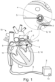
- Fig. 1 shows in a very schematic manner how the control system 3 can interact with a catheter 5 inserted for example through the femoral vein into the left atrium 6 and from there into a pulmonary vein 2.
- the catheter 5 may be a cryoballoon ablation catheter 5 that inflates at the entrance of a pulmonary vein 2 and is used to isolate the pulmonary vein 2.
- the catheter 5 comprises multiple electrodes 7.
- the catheter 5 comprises a spiral strand 8 with electrodes 7 that can be put into the pulmonary vein 2 to measure the intracardiac electrogram 1 before, during and after ablation.
- the control system 3 may further interact with a coronary sinus electrode 9, as shown in fig. 1.
- Fig. 1 shows only the sleeve of the coronary sinus electrode 9 entering the heart, the remainder of the coronary sinus electrode 9 is located in a plane outside the visible plane.
- the intracardiac electrogram 1 has been recorded by the electrodes 7. If the intracardiac electrogram 1 is a bipolar electrogram, it may have been measured between the electrodes 7.
- the electrodes 7 have a fixed order of placement on the catheter 5. It may be noted that all method steps described as features of the intracardiac electrogram 1 and not as part of the proposed method may alternatively be part of the proposed method.
- control system 3 determines an electrical status of the target region 4 by analysing at least three of the channels 10. This analysis can also be done, preferably in real time, during a surgery and/or by analysing an ongoing measurement of an intracardiac electrogram 1.
- the preferred use case of the present method is to analyse the electrical isolation status of the target region 4 with regards to, preferably during surgery for, atrial fibrillation.
- the analysis of the electrical isolation status of in particular the pulmonary veins 2 may be done during an episode of atrial fibrillation.
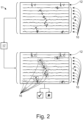
- Fig. 2 shows the channels 10 of the intracardiac electrogram 1 and a coronary sinus electrogram 12. There may also be more than one coronary sinus electrode 9 and more than one coronary sinus electrogram 12. It may be the case that one of the coronary sinus electrograms 12 is chosen for the present method or that more than one is used.
- predetermined target region means that the target region 4 has been selected by will and is not random.
- the predetermined target region 4 can be a pulmonary vein 2 which is to be isolated or which has been isolated and should now be measured to confirm the necessity of isolation or the success of isolation. In that case the exact location of the catheter 5 inside the pulmonary vein 2 is not critical as the whole vein should be electrically isolated from the left atrium 6.
- the predetermined target region 4 may also be a region associated with a rotor driving atrial fibrillation, which has been identified by a mapping system unrelated to the proposed analysis routine 11. Systems that electrically map the whole atrium 14 or both atria 14 usually do not measure predetermined regions, and instead measure a multitude of regions throughout the atria 14 successively.
- channel relates to a time row of electrical values, preferably voltages, measured by a unipolar electrode 7 or between at least two electrodes 7. Here and preferably, the channels 10 have been measured between neighbouring electrodes 7.
- intracardiac is to be understood broadly and relates to measurements inside the human heart 15 and in direct vicinity to it, for example in the pulmonary veins 2.
- a routine like the analysis routine 11, is a sum of steps with a purpose.
- the routine and the steps may be fully implemented in the control system 3 as software but may also comprise physical measurements and the like. Everything described as part of the routine serves the purpose of the routine, such that other calculations that may be done at the same time as the routine, but that are unrelated to the purpose of the routine, are not part of the routine.
- the steps of a routine can be done at separate times with space in-between, concurrently and in any sensible order.
- the order of the electrodes 7 implicitly or explicitly gives information about the order of the channels 10. It is generally known from so-called mapping systems or localization systems to use absolute spatial information from a localization system with an external reference. This can be a magnetic localization system, possible aided by bioimpedance measurements between a patch on the chest of the patient and the catheter 5. The present method does not rely on such an external reference.
- the main realization of the present invention is that it is possible to still use some of the advantages of a localization system in form of the relative spatial information by using the order of the electrodes 7 as, albeit relative, spatial information.
- the relative spatial information is solely based on the order of the electrodes 7.
- This order is fixed information based on the manufacturing of the catheter 5 and may be derived from the standard numbering of the channels 10 provided to the control system 3 simply by the order of the channel 10 measurements, for example.
- the control system 3 of the proposed method does preferably not use any absolute spatial information.
- the electrical status is an electrical isolation status of the target region 4 relative to the left and/or right atrium 14 and/or the rest of the left and/or right atrium 14. It may also comprise characteristics of the electrical conduction of the target region 4 itself.
- the term “determines based on” means that a feature, characteristic, property or the like is determined by using, in a not completely irrelevant manner, the information that the determination is "based on”. In every case it is preferably so that the determination is based mainly on the respective information.
- the intracardiac electrogram 1 has been recorded during a surgical procedure without electrical mapping of an atrium 14 by a localization system during the recording of the intracardiac electrogram 1 based on the recorded electrogram.
- a mapping system may be present additionally and independently, but in the preferred embodiment it is not. Preferably, that is the case during the whole surgical procedure.
- control system 3 preferably determines the electrical status by analysing concurrently measured channels 10 of the electrogram at the target region 4 without using electrogram channels 10 measured after repositioning of the catheter 5. It is one advantage of the present method that complex repositioning of the catheter 5 and measuring of a multitude of regions is not necessary. It may be mentioned that the target region 4 is not the whole left atrium 6 but significantly smaller.
- the spatial information is represented in a coordinate system without a reference point external to the body, in particular, without a reference point determined from a magnetic and/or bioimpedance measurement between an electrode 7 or magnetic localization apparatus outside the human body and the catheter 5 or even without a coordinate system.
- Imaging system like a CT-Scanner and the like are not included in the above if they do not provide a fixed reference system that the catheter 5 is related to.
- the channels 10 have been measured concurrently over at least partially, preferably completely, the same time period.
- the spatial information may be mainly or only passive spatial information that has not been measured over time, preferably not measured at all. In this last case, the term "measured" may not be understood broadly. Determining the order of the electrodes 7 from the numbering of the channels 10 or providing it from an external source where the order has been manually entered does not count as measuring the order.
- the spatial information has not been measured in a reference coordinate system and/or does not contain a reference coordinate system nor is related to one.
- the spatial information may be constant during the measurement of the intracardiac electrogram.
- the order of the electrodes 7 is constant, therefore, it may be the case that the spatial information does not or does not relevantly change during the proceeding and/or it may be the case that the spatial information does not comprise information that is updated regularly, in particular in real time or near real time.
- the electrical status is an electrical isolation status.
- the target region 4 is located inside a pulmonary vein 2 and the electrical isolation status is an electrical isolation status of the pulmonary vein 2.
- Pulmonary vein isolation is one of the main ablation therapies used.
- the intracardiac electrogram 1 may have been recorded after an isolation of a pulmonary vein 2 inside the isolated pulmonary vein 2 such that in the analysis routine 11 the control system 3 determines the pulmonary vein 2 isolation status. As stated above, the intracardiac electrogram 1 may also be recorded while running the analysis routine 11. When speaking about an isolation of the pulmonary veins 2, it is understood that an attempt on isolation is meant and the success is open to determination.
- the electrical isolation status may be a binary yes/no decision as shown in fig. 2 or a probability of isolation of the target region 4 or any other sensible measure of success.
- an activation candidate 16 is a section of a channel 10 that is identified by an algorithm as potentially being a local activation.
- the candidates may be identified using a peak detection algorithm, a waveform detection like a correlation or the like.
- the control system 3 performs a classification routine 17 for at least some, preferably all, of the activation candidates 16 classifying the activation candidates 16 into groups.
- the groups comprise at least one group assigned to local activations and/or at least one group assigned to far field interference, in particular atrial activations, and/or at least one group assigned to noise.
- the control system 3 can therefore separate the activation candidates 16 into real activations that do not have their origin in or near the target region 4, namely such activations that are far field interference, possibly artefacts, for example from pacing and noise, in particular false positives, namely signals that did not originate from a physiological activation and local activations.
- the local activations may be the main target of the proposed method and can be used to judge the electrical isolation status.
- channels 10 with low quality may be ignored in the classification routine 17 sometimes.
- the group is assigned to a certain type of signal it is meant that this type of signal or a subset of this type of signal is the main focus of said group and that the classification aims at, in particular solely, grouping occurrences of said type of signal into said group.
- the identification of the local activations during the classification routine 17 is at least partly based on detecting this timing difference.
- control system 3 differentiates between local activations and far field interference by identifying a propagation sequence along the order of the electrodes 7 and classifying activation candidates 16 as local activations if the control system 3 identifies a propagation sequence and/or as far field interference if the control system 3 does not identify a propagation sequence.
- control system 3 determines the electrical status based on a set of features determined from an analysis of channels 10 independently and a set of features determined from the analysis based on the spatial information, in particular the order of the electrodes 7.
- a possible set of features determined independently for each channel 10 is further described below.
- the control system 3 may determine the electrical status based on a local activation time difference between, in particular neighbouring, channels 10 based on the order of the electrodes 7.
- the activation can be an atrial activation detected in the coronary sinus electrogram 12 and the local activation time may be measured as a time difference between a certain event, for example the onset of an activation candidate 16, and the atrial activation.
- the local activation time is measured relative to any coronary activation, in particular measured by a coronary sinus electrode 9-
- the coronary activation may be an atrial activation.
- neighbouring channels 10 are preferably those that share an electrode 7 in usual bipolar measurements. Additionally or alternatively, neighbouring channels 10 may be spaced apart, for example by one electrode 7. In particular, some catheters 5 may have electrode 7 pairs with a space between the electrodes 7 of a pair being less than the space between electrodes 7 of neighbouring pairs.
- control system 3 determines the electrical status and/or the classification of an activation candidate 16 based on a change of an activation or activation candidate 16 over its spatial propagation whereby the spatial propagation is determined based on the spatial information, in particular the order of the electrodes 7, and the timing of the activation or activation candidate 16.
- This change can be a change of the waveform.
- the control system 3 estimates a quality indicator, in particular a signal-to-noise ratio, of a channel 10, preferably of all channels 10, based on the spatial information, in particular the order of the electrodes 7.
- This quality indicator may be used to remove some channels 10 from further analysis, preferably in the analysis routine 11, in particular in the classification routine 17.
- the control system 3 estimates the quality indicator based on a comparison of neighbouring channels 10, in particular waveforms of activations or activation candidates 16 of neighbouring channels 10.
- the control system 3, in the analysis routine 11 uses only a subset of the channels 10 selected based on the quality indicator to determine the electrical status of the target region 4.
- the subset here and preferably contains at least two, preferably at least 3, channels 10, but less than the maximum of the channels 10.
- the control system 3 may analyse a morphology of the local activations to determine the electrical isolation status of the target region 4. Preferably it is the case that in the analysis routine 11 the control system 3 classifies the local activations into morphology groups and preferably determines based on the distribution of local activations across the groups the electrical isolation status.
- the control system 3 classifies the local activations into the morphology groups based on a number of characteristic peaks of the local activation. For this, not every plateau of a local activation necessarily counts as a characteristic peak.
- the control system 3 classifies a peak with at least a predetermined amplitude and/or with at least a predetermined slope and/or with at most a predetermined slope and/or with at least a predetermined minimum peak distance and/or with at most a predetermined maximum peak distance and/or based on a peak morphology, in particular a minimum and/or maximum peak angle, as a characteristic peak.
- the morphology groups may comprise a group for local activations with a single characteristic peak and/or exactly two characteristic peaks and/or exactly three characteristic peaks and/or more than three characteristic peaks and/or at least two characteristic peaks separated by a predetermined time.
- the channels 10 may be highlighted, in particular coloured, based on the results or details of the analysis routine 11 by the control system 3 on a display of the control system 3. This is to draw attention of the physician to the impact and relation of the channels 10 on the model output and aid in interpretability.
- a control system 3 configured to perform the method according to the proposed method, wherein the control system 3 is configured to receive and/or measure the intracardiac electrogram 1, preferably wherein the control system 3 is connectable to the catheter 5, is proposed
Landscapes
- Health & Medical Sciences (AREA)
- Life Sciences & Earth Sciences (AREA)
- Cardiology (AREA)
- Engineering & Computer Science (AREA)
- Medical Informatics (AREA)
- Animal Behavior & Ethology (AREA)
- Pathology (AREA)
- Physics & Mathematics (AREA)
- Biomedical Technology (AREA)
- Heart & Thoracic Surgery (AREA)
- Veterinary Medicine (AREA)
- Molecular Biology (AREA)
- Surgery (AREA)
- Biophysics (AREA)
- General Health & Medical Sciences (AREA)
- Public Health (AREA)
- Physiology (AREA)
- Artificial Intelligence (AREA)
- Computer Vision & Pattern Recognition (AREA)
- Psychiatry (AREA)
- Signal Processing (AREA)
- Measurement And Recording Of Electrical Phenomena And Electrical Characteristics Of The Living Body (AREA)
- Surgical Instruments (AREA)
Description
- The present invention relates to a method for analysing an intracardiac electrogram according to the general part of claim 1 and to a control system according to
claim 14. - The present method is particularly concerned with atrial fibrillation and atrial flutter. Electrically, atrial fibrillation is chaotic activation of muscle cells of the atria. During atrial fibrillation, the atria only minimally contribute to the function of the heart. Atrial fibrillation, therefore, reduces the output of the heart but is not imminently dangerous. However, when becoming chronical, atrial fibrillation is correlated with increased morbidity and mortality. One treatment option for atrial fibrillation is ablation therapy. Ablation is the destruction of the cells that allow electrical wave re-entry to reduce chaotic activation of the atrial muscle cells.
- A recommended treatment for atrial fibrillation includes pulmonary vein isolation. Pulmonary vein isolation can be performed with various ablation techniques, including radio frequency ablation, cryoballoon ablation and pulsed-field ablation. While these techniques apply energy differently, their common endpoint is the isolation of the electrical activity of the pulmonary veins from the rest of the atrium.
- Generally, ablation therapy is successful, if the targeted location is electrically isolated from the rest of the heart. There are different methods for assessing the success of the ablation therapy. These include costly 3D mapping of ablation points, measurements of force or temperature during ablation and electrogram analysis.
- In a known method (
EP 3 139 828 A1US 2014/343388 A1 a basket mapping catheter used in an analysis using the order of electrodes is known. It discloses a method and system for mapping an anatomical structure includes sensing activation signals of intrinsic physiological activity with a plurality of mapping electrodes disposed in or near the anatomical structure, each of the plurality of mapping electrodes having an electrode location. A vector field map which represents a direction of propagation of the activation signals at each electrode location is generated to identify a signature pattern and a location in the vector field map according to at least one vector field template. A target location of the identified signature pattern is identified according to a corresponding electrode location. - It is a challenge to improve on the mentioned prior art. In particular, the electrical status of a target region in the heart, preferably in the pulmonary veins, should be detected more reliably.
- The invention is based on the problem of improving the known method such that a further optimization regarding the named challenge is reached.
- The above-noted object is solved by the features of the characterizing part of claim 1.
- The main realization of the present invention is that with catheters that do not have a localization system, it is still possible to derive spatial information and use this spatial information to improve the determination of an electrical status of a target region in the heart or the pulmonary veins. While the use of spatial information is known from mapping systems, sometimes also called localization systems, which use an external reference to localize the electrodes in a fixed coordinate system, the proposed method uses relative spatial information. This relative spatial information includes the order of the electrodes on the catheter. With this order it is not possible to derive an absolute position of the electrodes, but it can be used to find the propagation of wavefronts in the channels of an intracardiac electrogram. It is therefore possible to use spatial information in a system without an external spatial reference.
- In detail, it is proposed that the order of the electrodes on the catheter is provided to the control system or saved in a memory of the control system and that in the analysis routine the control system determines the electrical status of the target region based on spatial information including the order of placement of the electrodes on the catheter.
- One embodiment describes a number of preferred features that further define the use of the preferred method. These features primarily describe how the idea of using the order of the electrodes as spatial information can be used in various systems and use cases where no other localization is provided.
- One embodiment relates to the difference between the measurement of channels and the provision of the spatial information.
- Preferred catheters used to measure the intracardiac electrogram are object of one embodiment. Particularly, ablation catheters may be used to measure the electrogram prior to ablation and/or after ablation to assess the necessity of ablation and/or its success. Using the same catheter for the measurement and ablation leads to an effective, fast and cost-efficient approach for ablation. Following this train of thought, one embodiment describes preferred applications for the proposed method in the pulmonary veins. The entrances of the pulmonary veins are main targets for ablation therapy. Enabling an efficient measurement of the electrical isolation status of the pulmonary vein decreases surgery time and increases the therapy success for the patient.
- The success of ablation therapy in the pulmonary veins can be determined by analysing local activations in the pulmonary veins. If the activations spread towards the left atrium and activate the left atrium, the pulmonary veins are not fully isolated. If the activations are disconnected from the activation of the atrium, the isolation is likely successful. Conclusions about the isolation can be drawn from the waveform of the local activations. For that, it is necessary to differentiate between actual local activations and artefacts or far field interference, for example activations of the left atrium that spread towards the pulmonary veins. One difference between far field interference or artefacts and local activations is that local activations spread around the pulmonary veins, while far field interference and artefacts mostly do not.
- One embodiment relates to classifying activation candidates. If only or mainly local activations are grouped together, further analysis can be performed on that group of activations.
- The claimed invention is based on using timing sequence(s) and/or timing difference(s) between activations detected in different channels together with the spatial information to determine propagation of waves in the target region and thereby differentiate between local activations and far field interference.
- By combining the spatial information with features derived from the channels independently, an improved determination of the electrical status becomes possible.
- A measurement of the time between an activation and causing or caused by said activation like the onset of the heartbeat or the like, can vary between channels and conveys information about the electrical activity at the target region. This information can be used to judge the electrical status of the target region.
- As has been mentioned, the wave form of local activations is indicative of the isolation of a target region. Further the change of the waveform can be used to identify components of the wave that are subject to fast changes during propagation and components that are stable. In this way, further information about the waveform can be gained.
- A further advantage of using the order of electrodes on the catheter as spatial information is that it becomes possible to estimate the quality of the signal of a channel by comparing it to its neighbours and determining which signal components are local, physiological noise and which components are real noise.
- Embodiments relate to a specific algorithm for analysing the waveform of local activations. With the proposed improved method able to better detect local activations, the electrical isolation status of in particular the pulmonary veins can be estimated with more precision.
- Another teaching according to
claim 14, which is of equal importance, relates to a control system configured to perform the method according to the first teaching, wherein the control system is configured to receive and/or measure the intracardiac electrogram, preferably wherein the control system is connectable to the catheter. - All explanations given with respect to the proposed method are fully applicable to the control system.
- In the following, an embodiment of the invention is explained with respect to the drawing. The drawing shows in
- Fig. 1
- schematically a human heart and the use of the proposed control system during surgery to measure an intracardiac electrogram und
- Fig. 2
- a coronary sinus electrogram, an intracardiac electrogram and schematically the analysis and classification routines
- The proposed method is used for analysing an intracardiac electrogram 1. It can particularly well be used for detecting a
pulmonary vein 2 isolation status. The intracardiac electrogram 1 is analysed via acontrol system 3. The intracardiac electrogram 1 has been recorded at a, in particular predetermined,target region 4 via acatheter 5 inserted into a human body. -
Fig. 1 shows in a very schematic manner how thecontrol system 3 can interact with acatheter 5 inserted for example through the femoral vein into the left atrium 6 and from there into apulmonary vein 2. Thecatheter 5 may be acryoballoon ablation catheter 5 that inflates at the entrance of apulmonary vein 2 and is used to isolate thepulmonary vein 2. - The
catheter 5 comprisesmultiple electrodes 7. In the shown embodiment, thecatheter 5 comprises aspiral strand 8 withelectrodes 7 that can be put into thepulmonary vein 2 to measure the intracardiac electrogram 1 before, during and after ablation. - The
control system 3 may further interact with acoronary sinus electrode 9, as shown infig. 1. Fig. 1 shows only the sleeve of thecoronary sinus electrode 9 entering the heart, the remainder of thecoronary sinus electrode 9 is located in a plane outside the visible plane. - In the proposed method,
multiple channels 10 of the intracardiac electrogram 1 have been recorded by theelectrodes 7. If the intracardiac electrogram 1 is a bipolar electrogram, it may have been measured between theelectrodes 7. Theelectrodes 7 have a fixed order of placement on thecatheter 5. It may be noted that all method steps described as features of the intracardiac electrogram 1 and not as part of the proposed method may alternatively be part of the proposed method. - In an
analysis routine 11, thecontrol system 3 determines an electrical status of thetarget region 4 by analysing at least three of thechannels 10. This analysis can also be done, preferably in real time, during a surgery and/or by analysing an ongoing measurement of an intracardiac electrogram 1. - The preferred use case of the present method is to analyse the electrical isolation status of the
target region 4 with regards to, preferably during surgery for, atrial fibrillation. As will be further explained, it is one advantage of the proposed method that the analysis of the electrical isolation status of in particular thepulmonary veins 2 may be done during an episode of atrial fibrillation. -
Fig. 2 shows thechannels 10 of the intracardiac electrogram 1 and acoronary sinus electrogram 12. There may also be more than onecoronary sinus electrode 9 and more than onecoronary sinus electrogram 12. It may be the case that one of thecoronary sinus electrograms 12 is chosen for the present method or that more than one is used. - The
control system 3 may be a local unit with a processor, possibly a user interface and the like, as shown infig. 1 . It may also comprise in one embodiment a cloud processor. It is therefore not necessary for thecontrol system 3 to be confined to a single device. Thecontrol system 3 can have amemory 13 and other necessary components, in particular it may comprise an interface for thecatheter 5 and/or thecoronary sinus electrode 9. - The term "predetermined target region" means that the
target region 4 has been selected by will and is not random. Thepredetermined target region 4 can be apulmonary vein 2 which is to be isolated or which has been isolated and should now be measured to confirm the necessity of isolation or the success of isolation. In that case the exact location of thecatheter 5 inside thepulmonary vein 2 is not critical as the whole vein should be electrically isolated from the left atrium 6. Thepredetermined target region 4 may also be a region associated with a rotor driving atrial fibrillation, which has been identified by a mapping system unrelated to the proposedanalysis routine 11. Systems that electrically map thewhole atrium 14 or bothatria 14 usually do not measure predetermined regions, and instead measure a multitude of regions throughout theatria 14 successively. - The term "channel" relates to a time row of electrical values, preferably voltages, measured by a
unipolar electrode 7 or between at least twoelectrodes 7. Here and preferably, thechannels 10 have been measured between neighbouringelectrodes 7. - The term "intracardiac" is to be understood broadly and relates to measurements inside the
human heart 15 and in direct vicinity to it, for example in thepulmonary veins 2. - A routine, like the
analysis routine 11, is a sum of steps with a purpose. The routine and the steps may be fully implemented in thecontrol system 3 as software but may also comprise physical measurements and the like. Everything described as part of the routine serves the purpose of the routine, such that other calculations that may be done at the same time as the routine, but that are unrelated to the purpose of the routine, are not part of the routine. The steps of a routine can be done at separate times with space in-between, concurrently and in any sensible order. - It is essential here that the order of the
electrodes 7 on thecatheter 5 is provided to thecontrol system 3 or saved in amemory 13 of thecontrol system 3 and that in theanalysis routine 11 thecontrol system 3 determines the electrical status of thetarget region 4 based on relative spatial information including the order of placement of theelectrodes 7 on thecatheter 5. - Here and preferably, the order of the
electrodes 7 implicitly or explicitly gives information about the order of thechannels 10. It is generally known from so-called mapping systems or localization systems to use absolute spatial information from a localization system with an external reference. This can be a magnetic localization system, possible aided by bioimpedance measurements between a patch on the chest of the patient and thecatheter 5. The present method does not rely on such an external reference. The main realization of the present invention is that it is possible to still use some of the advantages of a localization system in form of the relative spatial information by using the order of theelectrodes 7 as, albeit relative, spatial information. Here and preferably, the relative spatial information is solely based on the order of theelectrodes 7. This order is fixed information based on the manufacturing of thecatheter 5 and may be derived from the standard numbering of thechannels 10 provided to thecontrol system 3 simply by the order of thechannel 10 measurements, for example. Thecontrol system 3 of the proposed method does preferably not use any absolute spatial information. - The electrical status is an electrical isolation status of the
target region 4 relative to the left and/orright atrium 14 and/or the rest of the left and/orright atrium 14. It may also comprise characteristics of the electrical conduction of thetarget region 4 itself. - Here and in the following the term "determines based on" means that a feature, characteristic, property or the like is determined by using, in a not completely irrelevant manner, the information that the determination is "based on". In every case it is preferably so that the determination is based mainly on the respective information.
- Here and preferably, the intracardiac electrogram 1 has been recorded during a surgical procedure without electrical mapping of an
atrium 14 by a localization system during the recording of the intracardiac electrogram 1 based on the recorded electrogram. A mapping system may be present additionally and independently, but in the preferred embodiment it is not. Preferably, that is the case during the whole surgical procedure. - In the
analysis routine 11 thecontrol system 3 preferably determines the electrical status by analysing concurrently measuredchannels 10 of the electrogram at thetarget region 4 without usingelectrogram channels 10 measured after repositioning of thecatheter 5. It is one advantage of the present method that complex repositioning of thecatheter 5 and measuring of a multitude of regions is not necessary. It may be mentioned that thetarget region 4 is not the whole left atrium 6 but significantly smaller. - Here and preferably, the spatial information is represented in a coordinate system without a reference point external to the body, in particular, without a reference point determined from a magnetic and/or bioimpedance measurement between an
electrode 7 or magnetic localization apparatus outside the human body and thecatheter 5 or even without a coordinate system. - Imaging system like a CT-Scanner and the like are not included in the above if they do not provide a fixed reference system that the
catheter 5 is related to. - Here and preferably the
channels 10 have been measured concurrently over at least partially, preferably completely, the same time period. The spatial information may be mainly or only passive spatial information that has not been measured over time, preferably not measured at all. In this last case, the term "measured" may not be understood broadly. Determining the order of theelectrodes 7 from the numbering of thechannels 10 or providing it from an external source where the order has been manually entered does not count as measuring the order. Preferably, the spatial information has not been measured in a reference coordinate system and/or does not contain a reference coordinate system nor is related to one. - The spatial information may be constant during the measurement of the intracardiac electrogram. Here, the order of the
electrodes 7 is constant, therefore, it may be the case that the spatial information does not or does not relevantly change during the proceeding and/or it may be the case that the spatial information does not comprise information that is updated regularly, in particular in real time or near real time. - As already mentioned and partially shown in
fig. 1 it may be the case that thecatheter 5 is anablation catheter 5, in particular acryoballoon catheter 5, and/or aspiral catheter 5, preferably, that thecatheter 5 comprises only asingle strand 8 on which theelectrodes 7 are located. An example of apreferred catheter 5 is the LASSO™ catheter 5. Alternatively, the catheter may be amultistrand catheter 5. In that case, the order of placement of theelectrodes 7 may relate to only onestrand 8 or to themultiple strands 8. - Here and preferably, it is the case that the electrical status is an electrical isolation status. Preferably, the
target region 4 is located inside apulmonary vein 2 and the electrical isolation status is an electrical isolation status of thepulmonary vein 2. Pulmonary vein isolation is one of the main ablation therapies used. The intracardiac electrogram 1 may have been recorded after an isolation of apulmonary vein 2 inside the isolatedpulmonary vein 2 such that in theanalysis routine 11 thecontrol system 3 determines thepulmonary vein 2 isolation status. As stated above, the intracardiac electrogram 1 may also be recorded while running theanalysis routine 11. When speaking about an isolation of thepulmonary veins 2, it is understood that an attempt on isolation is meant and the success is open to determination. - The electrical isolation status may be a binary yes/no decision as shown in
fig. 2 or a probability of isolation of thetarget region 4 or any other sensible measure of success. - It is the case that in the
analysis routine 11 thecontrol system 3 identifiesactivation candidates 16 in at least three of thechannels 10, in particular in allchannels 10. Anactivation candidate 16 is a section of achannel 10 that is identified by an algorithm as potentially being a local activation. The candidates may be identified using a peak detection algorithm, a waveform detection like a correlation or the like. - In the
analysis routine 11 thecontrol system 3 performs aclassification routine 17 for at least some, preferably all, of theactivation candidates 16 classifying theactivation candidates 16 into groups. The groups comprise at least one group assigned to local activations and/or at least one group assigned to far field interference, in particular atrial activations, and/or at least one group assigned to noise. Thecontrol system 3 can therefore separate theactivation candidates 16 into real activations that do not have their origin in or near thetarget region 4, namely such activations that are far field interference, possibly artefacts, for example from pacing and noise, in particular false positives, namely signals that did not originate from a physiological activation and local activations. The local activations may be the main target of the proposed method and can be used to judge the electrical isolation status. - As will be further explained,
channels 10 with low quality may be ignored in theclassification routine 17 sometimes. - When saying that the group is assigned to a certain type of signal it is meant that this type of signal or a subset of this type of signal is the main focus of said group and that the classification aims at, in particular solely, grouping occurrences of said type of signal into said group.
- By placing a, particularly spiral,
catheter 5 inside apulmonary vein 2, the propagation of the local activation around thepulmonary vein 2 can be detected. This is based on the realization that, in particular in thepulmonary veins 2, far field interference like atrial beats and artefacts like pacing artefacts will reach most of thepulmonary vein 2 at the same time, particularly if theelectrodes 7 are arranged more or less orthogonal to the extension of thepulmonary vein 2 at the circumference of thepulmonary vein 2 for example by using a circular orspiral catheter 5 orstrand 8. Local activations however propagate around thepulmonary veins 2. This propagation can be measured as a time difference between the onset or peaks of the local activations.Fig. 2 shows local activations in somechannels 10 with their respective different timings. - Here and preferably, the identification of the local activations during the
classification routine 17 is at least partly based on detecting this timing difference. - In detail, it may be the case that in the
classification routine 17 thecontrol system 3 identifies a timing sequence and/or a timing difference between at least two, preferably at least three, more preferably at least four,activation candidates 16 ofdifferent channels 10 based on the spatial information, in particular the order of theelectrodes 7, preferably to differentiate between local activations and far field interference. - Further, it is possible that in the
classification routine 17 thecontrol system 3 differentiates between local activations and far field interference by identifying a propagation sequence along the order of theelectrodes 7 and classifyingactivation candidates 16 as local activations if thecontrol system 3 identifies a propagation sequence and/or as far field interference if thecontrol system 3 does not identify a propagation sequence. - It is interesting to note that during atrial fibrillation the time relation between atrial beats and local activations in the
pulmonary veins 2 may be broken. Know algorithms therefore have trouble differentiating local activations from far field interference, particularly atrial activations. The above can be used to aid this differentiation. Therefore, the proposed method works well during episodes of atrial fibrillation. By using this method, a surgeon may not have to cardiovert a patients atria 14 to normal rhythm to measure the success of the isolation procedure. - In the preferred embodiment, in the
analysis routine 11, thecontrol system 3 determines the electrical status based on a set of features determined from an analysis ofchannels 10 independently and a set of features determined from the analysis based on the spatial information, in particular the order of theelectrodes 7. A possible set of features determined independently for eachchannel 10 is further described below. - In the
analysis routine 11, in particular in theclassification routine 17, thecontrol system 3 may determine the electrical status based on a local activation time difference between, in particular neighbouring,channels 10 based on the order of theelectrodes 7. The activation can be an atrial activation detected in thecoronary sinus electrogram 12 and the local activation time may be measured as a time difference between a certain event, for example the onset of anactivation candidate 16, and the atrial activation. Preferably, the local activation time is measured relative to any coronary activation, in particular measured by a coronary sinus electrode 9- The coronary activation may be an atrial activation. - It may be reiterated that neighbouring
channels 10 are preferably those that share anelectrode 7 in usual bipolar measurements. Additionally or alternatively, neighbouringchannels 10 may be spaced apart, for example by oneelectrode 7. In particular, somecatheters 5 may haveelectrode 7 pairs with a space between theelectrodes 7 of a pair being less than the space betweenelectrodes 7 of neighbouring pairs. - Further, it is possible that in the
analysis routine 11, in particular in theclassification routine 17, thecontrol system 3 determines the electrical status and/or the classification of anactivation candidate 16 based on a change of an activation oractivation candidate 16 over its spatial propagation whereby the spatial propagation is determined based on the spatial information, in particular the order of theelectrodes 7, and the timing of the activation oractivation candidate 16. This change can be a change of the waveform. - Another advantage of using the relative spatial information is the possibility of estimating the quality of a
channel 10. Here and preferably in a quality estimation routine, preferably prior to theanalysis routine 11, thecontrol system 3 estimates a quality indicator, in particular a signal-to-noise ratio, of achannel 10, preferably of allchannels 10, based on the spatial information, in particular the order of theelectrodes 7. This quality indicator may be used to remove somechannels 10 from further analysis, preferably in theanalysis routine 11, in particular in theclassification routine 17. Preferably, in the quality estimation routine, thecontrol system 3 estimates the quality indicator based on a comparison of neighbouringchannels 10, in particular waveforms of activations oractivation candidates 16 of neighbouringchannels 10. Additionally or alternatively, thecontrol system 3, in theanalysis routine 11, uses only a subset of thechannels 10 selected based on the quality indicator to determine the electrical status of thetarget region 4. - The subset here and preferably contains at least two, preferably at least 3,
channels 10, but less than the maximum of thechannels 10. - As already mentioned, to determine the electrical isolation status, in the
analysis routine 11, thecontrol system 3 may analyse a morphology of the local activations to determine the electrical isolation status of thetarget region 4. Preferably it is the case that in theanalysis routine 11 thecontrol system 3 classifies the local activations into morphology groups and preferably determines based on the distribution of local activations across the groups the electrical isolation status. - Here and preferably, in the
analysis routine 11, thecontrol system 3 classifies the local activations into the morphology groups based on a number of characteristic peaks of the local activation. For this, not every plateau of a local activation necessarily counts as a characteristic peak. Preferably, thecontrol system 3 classifies a peak with at least a predetermined amplitude and/or with at least a predetermined slope and/or with at most a predetermined slope and/or with at least a predetermined minimum peak distance and/or with at most a predetermined maximum peak distance and/or based on a peak morphology, in particular a minimum and/or maximum peak angle, as a characteristic peak. - Further, the morphology groups may comprise a group for local activations with a single characteristic peak and/or exactly two characteristic peaks and/or exactly three characteristic peaks and/or more than three characteristic peaks and/or at least two characteristic peaks separated by a predetermined time.
- The
channels 10 may be highlighted, in particular coloured, based on the results or details of theanalysis routine 11 by thecontrol system 3 on a display of thecontrol system 3. This is to draw attention of the physician to the impact and relation of thechannels 10 on the model output and aid in interpretability. - According to a further teaching with equal importance, a
control system 3 configured to perform the method according to the proposed method, wherein thecontrol system 3 is configured to receive and/or measure the intracardiac electrogram 1, preferably wherein thecontrol system 3 is connectable to thecatheter 5, is proposed - All explanations given with regard to the proposed method are fully applicable to the
control system 3. -
- 1
- intracardiac electrogram
- 2
- pulmonary vein
- 3
- control system
- 4
- target region
- 5
- catheter
- 6
- left atrium
- 7
- electrode
- 8
- strand
- 9
- coronary sinus electrode
- 10
- channel
- 11
- analysis routine
- 12
- coronary sinus electrogram
- 13
- memory
- 14
- atrium
- 15
- human heart
- 16
- activation candidate
- 17
- classification routine
Claims (14)
- Method for analysing an intracardiac electrogram (1), in particular for detecting a pulmonary vein (2) isolation status, via a control system (3), wherein the intracardiac electrogram (1) has been recorded at a, in particular predetermined, target region (4) via a catheter (5) inserted into a human body, wherein the catheter (5) comprises multiple electrodes (7), wherein multiple channels (10) of the intracardiac electrogram (1) have been recorded by, preferably between, the electrodes (7), wherein the electrodes (7) have a fixed order of placement on the catheter (5),wherein in an analysis routine (11), the control system (3) determines an electrical status of the target region (4) by analysing at least three of the channels (10),wherein the order of the electrodes (7) on the catheter (5) is provided to the control system (3) or saved in a memory (13) of the control system (3) and that in the analysis routine (11) the control system (3) determines the electrical status of the target region (4) based on relative spatial information including the order of placement of the electrodes (7) on the catheter (5),wherein in the analysis routine (11) the control system (3) identifies activation candidates (16) in at least three of the channels (10), wherein in the analysis routine (11) the control system (3) performs a classification routine (17) for at least some of the activation candidates (16) classifying the activation candidates (16) into groups, the groups comprising at least one group assigned to local activations and/or at least one group assigned to far field interference, characterized inthat in the classification routine (17) the control system (3) identifies a timing sequence and/or a timing difference between at least two activation candidates (16) of different channels (10) based on the spatial information to differentiate between local activations and far field interference andthat the electrical status is an electrical isolation status of the target region (4) relative to the left and/or right atrium (14) and/or the rest of the left and/or right atrium (14).
- Method according to claim 1, characterized in that the channels (10) have been measured concurrently over at least partially the same time period.
- Method according to claim 1 or 2, characterized in that the catheter (5) comprises only a single strand (8) on which the electrodes (7) are located.
- Method according one of the preceding claims, characterized in that in the analysis routine (11) the control system (3) performs the classification routine (17) for all of the activation candidates (16)
- Method according to one of the preceding claims, characterized in that in the classification routine (17) the control system (3) identifies a timing sequence between at least three activation candidates (16) of different channels (10) based on the spatial information, and, that in the classification routine (17) the control system (3) differentiates between local activations and far field interference by identifying a propagation sequence along the order of the electrodes (7) and classifying activation candidates (16) as local activations if the control system (3) identifies a propagation sequence and as far field interference if the control system (3) does not identify a propagation sequence.
- Method according to one of the preceding claims, characterized in that in the classification routine (17) the control system (3) determines the electrical status based on a local activation time difference between channels (10) based on the order of the electrodes (7).
- Method according to claim 5 or 6, characterized in that in the analysis routine (11) the control system (3) determines the electrical status based on a change of an activation or activation candidate (16) over its spatial propagation whereby the spatial propagation is determined based on the spatial information and the timing of the activation or activation candidate (16).
- Method according to one of the preceding claims, characterized in that in a quality estimation routine the control system (3) estimates a quality indicator of a channel (10) based on the spatial information.
- Method according to claim 8, characterized in that in the quality estimation routine the control system (3) estimates the quality indicator based on a comparison of neighbouring channels (10), and, that the control system (3) in the analysis routine (11) uses only a subset of the channels (10) selected based on the quality indicator to determine the electrical status of the target region (4).
- Method according to one of the preceding claims, characterized in that in the analysis routine (11) the control system (3) analyses a morphology of the local activations to determine the electrical isolation status of the target region (4).
- Method according to claim 10, characterized in that in the analysis routine (11) the control system (3) classifies the local activations into morphology groups and determines based on the distribution of local activations across the groups the electrical isolation status.
- Method according to claim 11, characterized in that in the analysis routine (11) the control system (3) classifies the local activations into the morphology groups based on a number of characteristic peaks of the local activation.
- Method according to claim 11 or 12, characterized in that the morphology groups comprise a group for local activations with a single characteristic peak and exactly two characteristic peaks and at least two characteristic peaks separated by a predetermined time.
- Control system, wherein the control system (3) is configured to receive and/or measure an intracardiac electrogram (1), wherein the control system (3) is a local unit with a processor and a user interface, wherein the control system (3) has a memory (13) and comprises an interface for a catheter (5) comprising multiple electrodes (7) with a fixed order of placement of the electrodes on the catheter (5), wherein the control system (3) is configured to perform the method according to one of the preceding claims, wherein the routines of the method are fully implemented in the control system (3) as software,
wherein the order of the electrodes (7) on the catheter (5) is saved in the memory (13) of the control system (3).
Priority Applications (6)
| Application Number | Priority Date | Filing Date | Title |
|---|---|---|---|
| EP21211744.4A EP4190239B1 (en) | 2021-12-01 | 2021-12-01 | Method for analysing an intracardiac electrogram |
| ES21211744T ES3025890T3 (en) | 2021-12-01 | 2021-12-01 | Method for analysing an intracardiac electrogram |
| PCT/EP2022/082768 WO2023099280A1 (en) | 2021-12-01 | 2022-11-22 | Method for analysing an intracardiac electrogram |
| JP2024532864A JP7775476B2 (en) | 2021-12-01 | 2022-11-22 | Method for analyzing intracardiac electrograms |
| US18/714,216 US20250032033A1 (en) | 2021-12-01 | 2022-11-22 | Method for analysing an intracardiac electrogram |
| CN202280079897.4A CN118338844A (en) | 2021-12-01 | 2022-11-22 | Method for analyzing intracardiac electrograms |
Applications Claiming Priority (1)
| Application Number | Priority Date | Filing Date | Title |
|---|---|---|---|
| EP21211744.4A EP4190239B1 (en) | 2021-12-01 | 2021-12-01 | Method for analysing an intracardiac electrogram |
Publications (3)
| Publication Number | Publication Date |
|---|---|
| EP4190239A1 EP4190239A1 (en) | 2023-06-07 |
| EP4190239C0 EP4190239C0 (en) | 2025-03-19 |
| EP4190239B1 true EP4190239B1 (en) | 2025-03-19 |
Family
ID=78820732
Family Applications (1)
| Application Number | Title | Priority Date | Filing Date |
|---|---|---|---|
| EP21211744.4A Active EP4190239B1 (en) | 2021-12-01 | 2021-12-01 | Method for analysing an intracardiac electrogram |
Country Status (6)
| Country | Link |
|---|---|
| US (1) | US20250032033A1 (en) |
| EP (1) | EP4190239B1 (en) |
| JP (1) | JP7775476B2 (en) |
| CN (1) | CN118338844A (en) |
| ES (1) | ES3025890T3 (en) |
| WO (1) | WO2023099280A1 (en) |
Citations (3)
| Publication number | Priority date | Publication date | Assignee | Title |
|---|---|---|---|---|
| WO2002056783A1 (en) * | 2000-12-11 | 2002-07-25 | C.R. Bard, Inc. | Microelectrode catheter for mapping and ablation |
| US20130345577A1 (en) * | 2012-06-20 | 2013-12-26 | Boston Scientific Scimed, Inc. | Augmented signal vector analysis to suppress global activation during electrophysiology mapping |
| US20210177293A1 (en) * | 2019-12-12 | 2021-06-17 | Biosense Webster (Israel) Ltd. | Detection of ventricular activity using unipolar and bipolar signals |
Family Cites Families (6)
| Publication number | Priority date | Publication date | Assignee | Title |
|---|---|---|---|---|
| US9220433B2 (en) * | 2011-06-30 | 2015-12-29 | Biosense Webster (Israel), Ltd. | Catheter with variable arcuate distal section |
| JP6182665B2 (en) * | 2013-05-14 | 2017-08-16 | ボストン サイエンティフィック サイムド,インコーポレイテッドBoston Scientific Scimed,Inc. | Catheter system for the display and identification of activity patterns during electrophysiological mapping using vector fields |
| EP3139828B1 (en) | 2014-05-09 | 2019-10-16 | Universiteit Gent | Detection of pulmonary vein isolation |
| US11109788B2 (en) * | 2017-07-17 | 2021-09-07 | Biosense Webster (Israel) Ltd. | Catheter with Fibonacci distributed electrodes |
| EP3801341B1 (en) * | 2018-06-07 | 2025-03-12 | Donald Rubenstein | Methods for tracking rotational activation sites in atrial fibrillation |
| US20200138334A1 (en) * | 2018-11-07 | 2020-05-07 | St. Jude Medical International Holding S.à.r.I. | Method for medical device localization based on magnetic and impedance sensors |
-
2021
- 2021-12-01 EP EP21211744.4A patent/EP4190239B1/en active Active
- 2021-12-01 ES ES21211744T patent/ES3025890T3/en active Active
-
2022
- 2022-11-22 CN CN202280079897.4A patent/CN118338844A/en active Pending
- 2022-11-22 US US18/714,216 patent/US20250032033A1/en active Pending
- 2022-11-22 WO PCT/EP2022/082768 patent/WO2023099280A1/en not_active Ceased
- 2022-11-22 JP JP2024532864A patent/JP7775476B2/en active Active
Patent Citations (3)
| Publication number | Priority date | Publication date | Assignee | Title |
|---|---|---|---|---|
| WO2002056783A1 (en) * | 2000-12-11 | 2002-07-25 | C.R. Bard, Inc. | Microelectrode catheter for mapping and ablation |
| US20130345577A1 (en) * | 2012-06-20 | 2013-12-26 | Boston Scientific Scimed, Inc. | Augmented signal vector analysis to suppress global activation during electrophysiology mapping |
| US20210177293A1 (en) * | 2019-12-12 | 2021-06-17 | Biosense Webster (Israel) Ltd. | Detection of ventricular activity using unipolar and bipolar signals |
Also Published As
| Publication number | Publication date |
|---|---|
| ES3025890T3 (en) | 2025-06-10 |
| JP7775476B2 (en) | 2025-11-25 |
| WO2023099280A1 (en) | 2023-06-08 |
| EP4190239C0 (en) | 2025-03-19 |
| EP4190239A1 (en) | 2023-06-07 |
| CN118338844A (en) | 2024-07-12 |
| JP2024543583A (en) | 2024-11-21 |
| US20250032033A1 (en) | 2025-01-30 |
Similar Documents
| Publication | Publication Date | Title |
|---|---|---|
| EP2996550B1 (en) | Representation and identification of activity patterns during electro-physiology mapping using vector fields | |
| US10010258B2 (en) | Atrial fibrillation treatment systems and methods | |
| EP3192442B1 (en) | Non-overlapping loop-type catheter to determine activation source direction and activation source type | |
| US9687167B2 (en) | Medical devices for mapping cardiac tissue | |
| US9579034B2 (en) | Enhanced activation onset time optimization by similarity based pattern matching | |
| EP3001949A1 (en) | System and method for reconstructing cardiac activation information | |
| US11331033B2 (en) | Systems and methods for treating cardiac arrhythmia | |
| US20240350065A1 (en) | Method for detecting a cardiac isolation status of a measurement location in the presence of far field interference | |
| CN112842353B (en) | Mapping local activation times of sinus and non-sinus cardiac cycles | |
| US20220202345A1 (en) | Method and apparatus to find abnormal activations in intra-cardiac electrocardiograms based on specificity and sensitivity | |
| US20250032033A1 (en) | Method for analysing an intracardiac electrogram | |
| Petrutiu et al. | Time domain analysis of atrial fibrillation | |
| Shokrollahi et al. | Efficacy of noncontact mapping in detecting epicardial activation |
Legal Events
| Date | Code | Title | Description |
|---|---|---|---|
| STAA | Information on the status of an ep patent application or granted ep patent |
Free format text: STATUS: EXAMINATION IS IN PROGRESS |
|
| PUAI | Public reference made under article 153(3) epc to a published international application that has entered the european phase |
Free format text: ORIGINAL CODE: 0009012 |
|
| 17P | Request for examination filed |
Effective date: 20230127 |
|
| AK | Designated contracting states |
Kind code of ref document: A1 Designated state(s): AL AT BE BG CH CY CZ DE DK EE ES FI FR GB GR HR HU IE IS IT LI LT LU LV MC MK MT NL NO PL PT RO RS SE SI SK SM TR |
|
| GRAP | Despatch of communication of intention to grant a patent |
Free format text: ORIGINAL CODE: EPIDOSNIGR1 |
|
| STAA | Information on the status of an ep patent application or granted ep patent |
Free format text: STATUS: GRANT OF PATENT IS INTENDED |
|
| INTG | Intention to grant announced |
Effective date: 20241018 |
|
| GRAS | Grant fee paid |
Free format text: ORIGINAL CODE: EPIDOSNIGR3 |
|
| GRAA | (expected) grant |
Free format text: ORIGINAL CODE: 0009210 |
|
| STAA | Information on the status of an ep patent application or granted ep patent |
Free format text: STATUS: THE PATENT HAS BEEN GRANTED |
|
| AK | Designated contracting states |
Kind code of ref document: B1 Designated state(s): AL AT BE BG CH CY CZ DE DK EE ES FI FR GB GR HR HU IE IS IT LI LT LU LV MC MK MT NL NO PL PT RO RS SE SI SK SM TR |
|
| REG | Reference to a national code |
Ref country code: GB Ref legal event code: FG4D |
|
| REG | Reference to a national code |
Ref country code: CH Ref legal event code: EP |
|
| REG | Reference to a national code |
Ref country code: DE Ref legal event code: R096 Ref document number: 602021027760 Country of ref document: DE |
|
| REG | Reference to a national code |
Ref country code: IE Ref legal event code: FG4D |
|
| U01 | Request for unitary effect filed |
Effective date: 20250404 |
|
| U07 | Unitary effect registered |
Designated state(s): AT BE BG DE DK EE FI FR IT LT LU LV MT NL PT RO SE SI Effective date: 20250411 |
|
| REG | Reference to a national code |
Ref country code: ES Ref legal event code: FG2A Ref document number: 3025890 Country of ref document: ES Kind code of ref document: T3 Effective date: 20250610 |
|
| PG25 | Lapsed in a contracting state [announced via postgrant information from national office to epo] |
Ref country code: RS Free format text: LAPSE BECAUSE OF FAILURE TO SUBMIT A TRANSLATION OF THE DESCRIPTION OR TO PAY THE FEE WITHIN THE PRESCRIBED TIME-LIMIT Effective date: 20250619 |
|
| PG25 | Lapsed in a contracting state [announced via postgrant information from national office to epo] |
Ref country code: NO Free format text: LAPSE BECAUSE OF FAILURE TO SUBMIT A TRANSLATION OF THE DESCRIPTION OR TO PAY THE FEE WITHIN THE PRESCRIBED TIME-LIMIT Effective date: 20250619 |
|
| PG25 | Lapsed in a contracting state [announced via postgrant information from national office to epo] |
Ref country code: HR Free format text: LAPSE BECAUSE OF FAILURE TO SUBMIT A TRANSLATION OF THE DESCRIPTION OR TO PAY THE FEE WITHIN THE PRESCRIBED TIME-LIMIT Effective date: 20250319 |
|
| PG25 | Lapsed in a contracting state [announced via postgrant information from national office to epo] |
Ref country code: GR Free format text: LAPSE BECAUSE OF FAILURE TO SUBMIT A TRANSLATION OF THE DESCRIPTION OR TO PAY THE FEE WITHIN THE PRESCRIBED TIME-LIMIT Effective date: 20250620 |
|
| PG25 | Lapsed in a contracting state [announced via postgrant information from national office to epo] |
Ref country code: SM Free format text: LAPSE BECAUSE OF FAILURE TO SUBMIT A TRANSLATION OF THE DESCRIPTION OR TO PAY THE FEE WITHIN THE PRESCRIBED TIME-LIMIT Effective date: 20250319 |
|
| PG25 | Lapsed in a contracting state [announced via postgrant information from national office to epo] |
Ref country code: PL Free format text: LAPSE BECAUSE OF FAILURE TO SUBMIT A TRANSLATION OF THE DESCRIPTION OR TO PAY THE FEE WITHIN THE PRESCRIBED TIME-LIMIT Effective date: 20250319 |
|
| PG25 | Lapsed in a contracting state [announced via postgrant information from national office to epo] |
Ref country code: CZ Free format text: LAPSE BECAUSE OF FAILURE TO SUBMIT A TRANSLATION OF THE DESCRIPTION OR TO PAY THE FEE WITHIN THE PRESCRIBED TIME-LIMIT Effective date: 20250319 |
|
| PG25 | Lapsed in a contracting state [announced via postgrant information from national office to epo] |
Ref country code: SK Free format text: LAPSE BECAUSE OF FAILURE TO SUBMIT A TRANSLATION OF THE DESCRIPTION OR TO PAY THE FEE WITHIN THE PRESCRIBED TIME-LIMIT Effective date: 20250319 |
|
| PG25 | Lapsed in a contracting state [announced via postgrant information from national office to epo] |
Ref country code: IS Free format text: LAPSE BECAUSE OF FAILURE TO SUBMIT A TRANSLATION OF THE DESCRIPTION OR TO PAY THE FEE WITHIN THE PRESCRIBED TIME-LIMIT Effective date: 20250719 |
|
| PGFP | Annual fee paid to national office [announced via postgrant information from national office to epo] |
Ref country code: GB Payment date: 20251219 Year of fee payment: 5 |
|
| PLBE | No opposition filed within time limit |
Free format text: ORIGINAL CODE: 0009261 |
|
| STAA | Information on the status of an ep patent application or granted ep patent |
Free format text: STATUS: NO OPPOSITION FILED WITHIN TIME LIMIT |
|
| REG | Reference to a national code |
Ref country code: CH Ref legal event code: L10 Free format text: ST27 STATUS EVENT CODE: U-0-0-L10-L00 (AS PROVIDED BY THE NATIONAL OFFICE) Effective date: 20260128 |
|
| U20 | Renewal fee for the european patent with unitary effect paid |
Year of fee payment: 5 Effective date: 20251223 |
|
| 26N | No opposition filed |
Effective date: 20251222 |
|
| PGFP | Annual fee paid to national office [announced via postgrant information from national office to epo] |
Ref country code: ES Payment date: 20260130 Year of fee payment: 5 |
|
| PG25 | Lapsed in a contracting state [announced via postgrant information from national office to epo] |
Ref country code: MC Free format text: LAPSE BECAUSE OF FAILURE TO SUBMIT A TRANSLATION OF THE DESCRIPTION OR TO PAY THE FEE WITHIN THE PRESCRIBED TIME-LIMIT Effective date: 20250319 |
|
| REG | Reference to a national code |
Ref country code: CH Ref legal event code: H13 Free format text: ST27 STATUS EVENT CODE: U-0-0-H10-H13 (AS PROVIDED BY THE NATIONAL OFFICE) Effective date: 20260723 |