EP4190208A1 - Refrigerated display cabinet foldable baffles - Google Patents
Refrigerated display cabinet foldable baffles Download PDFInfo
- Publication number
- EP4190208A1 EP4190208A1 EP22210951.4A EP22210951A EP4190208A1 EP 4190208 A1 EP4190208 A1 EP 4190208A1 EP 22210951 A EP22210951 A EP 22210951A EP 4190208 A1 EP4190208 A1 EP 4190208A1
- Authority
- EP
- European Patent Office
- Prior art keywords
- baffle
- door
- refrigerated
- display cabinet
- cabinet
- Prior art date
- Legal status (The legal status is an assumption and is not a legal conclusion. Google has not performed a legal analysis and makes no representation as to the accuracy of the status listed.)
- Withdrawn
Links
Images




Classifications
-
- A—HUMAN NECESSITIES
- A47—FURNITURE; DOMESTIC ARTICLES OR APPLIANCES; COFFEE MILLS; SPICE MILLS; SUCTION CLEANERS IN GENERAL
- A47F—SPECIAL FURNITURE, FITTINGS, OR ACCESSORIES FOR SHOPS, STOREHOUSES, BARS, RESTAURANTS OR THE LIKE; PAYING COUNTERS
- A47F3/00—Show cases or show cabinets
- A47F3/04—Show cases or show cabinets air-conditioned, refrigerated
- A47F3/0404—Cases or cabinets of the closed type
-
- A—HUMAN NECESSITIES
- A47—FURNITURE; DOMESTIC ARTICLES OR APPLIANCES; COFFEE MILLS; SPICE MILLS; SUCTION CLEANERS IN GENERAL
- A47F—SPECIAL FURNITURE, FITTINGS, OR ACCESSORIES FOR SHOPS, STOREHOUSES, BARS, RESTAURANTS OR THE LIKE; PAYING COUNTERS
- A47F3/00—Show cases or show cabinets
- A47F3/04—Show cases or show cabinets air-conditioned, refrigerated
- A47F3/0404—Cases or cabinets of the closed type
- A47F3/0426—Details
- A47F3/0434—Glass or transparent panels
-
- A—HUMAN NECESSITIES
- A47—FURNITURE; DOMESTIC ARTICLES OR APPLIANCES; COFFEE MILLS; SPICE MILLS; SUCTION CLEANERS IN GENERAL
- A47F—SPECIAL FURNITURE, FITTINGS, OR ACCESSORIES FOR SHOPS, STOREHOUSES, BARS, RESTAURANTS OR THE LIKE; PAYING COUNTERS
- A47F3/00—Show cases or show cabinets
- A47F3/04—Show cases or show cabinets air-conditioned, refrigerated
- A47F3/0404—Cases or cabinets of the closed type
- A47F3/0426—Details
- A47F3/043—Doors, covers
-
- A—HUMAN NECESSITIES
- A47—FURNITURE; DOMESTIC ARTICLES OR APPLIANCES; COFFEE MILLS; SPICE MILLS; SUCTION CLEANERS IN GENERAL
- A47F—SPECIAL FURNITURE, FITTINGS, OR ACCESSORIES FOR SHOPS, STOREHOUSES, BARS, RESTAURANTS OR THE LIKE; PAYING COUNTERS
- A47F3/00—Show cases or show cabinets
- A47F3/04—Show cases or show cabinets air-conditioned, refrigerated
- A47F3/0404—Cases or cabinets of the closed type
- A47F3/0426—Details
-
- F—MECHANICAL ENGINEERING; LIGHTING; HEATING; WEAPONS; BLASTING
- F25—REFRIGERATION OR COOLING; COMBINED HEATING AND REFRIGERATION SYSTEMS; HEAT PUMP SYSTEMS; MANUFACTURE OR STORAGE OF ICE; LIQUEFACTION SOLIDIFICATION OF GASES
- F25D—REFRIGERATORS; COLD ROOMS; ICE-BOXES; COOLING OR FREEZING APPARATUS NOT OTHERWISE PROVIDED FOR
- F25D23/00—General constructional features
-
- F—MECHANICAL ENGINEERING; LIGHTING; HEATING; WEAPONS; BLASTING
- F25—REFRIGERATION OR COOLING; COMBINED HEATING AND REFRIGERATION SYSTEMS; HEAT PUMP SYSTEMS; MANUFACTURE OR STORAGE OF ICE; LIQUEFACTION SOLIDIFICATION OF GASES
- F25D—REFRIGERATORS; COLD ROOMS; ICE-BOXES; COOLING OR FREEZING APPARATUS NOT OTHERWISE PROVIDED FOR
- F25D23/00—General constructional features
- F25D23/02—Doors; Covers
-
- F—MECHANICAL ENGINEERING; LIGHTING; HEATING; WEAPONS; BLASTING
- F25—REFRIGERATION OR COOLING; COMBINED HEATING AND REFRIGERATION SYSTEMS; HEAT PUMP SYSTEMS; MANUFACTURE OR STORAGE OF ICE; LIQUEFACTION SOLIDIFICATION OF GASES
- F25D—REFRIGERATORS; COLD ROOMS; ICE-BOXES; COOLING OR FREEZING APPARATUS NOT OTHERWISE PROVIDED FOR
- F25D23/00—General constructional features
- F25D23/02—Doors; Covers
- F25D23/025—Secondary closures
-
- F—MECHANICAL ENGINEERING; LIGHTING; HEATING; WEAPONS; BLASTING
- F25—REFRIGERATION OR COOLING; COMBINED HEATING AND REFRIGERATION SYSTEMS; HEAT PUMP SYSTEMS; MANUFACTURE OR STORAGE OF ICE; LIQUEFACTION SOLIDIFICATION OF GASES
- F25D—REFRIGERATORS; COLD ROOMS; ICE-BOXES; COOLING OR FREEZING APPARATUS NOT OTHERWISE PROVIDED FOR
- F25D23/00—General constructional features
- F25D23/02—Doors; Covers
- F25D23/028—Details
-
- F—MECHANICAL ENGINEERING; LIGHTING; HEATING; WEAPONS; BLASTING
- F25—REFRIGERATION OR COOLING; COMBINED HEATING AND REFRIGERATION SYSTEMS; HEAT PUMP SYSTEMS; MANUFACTURE OR STORAGE OF ICE; LIQUEFACTION SOLIDIFICATION OF GASES
- F25D—REFRIGERATORS; COLD ROOMS; ICE-BOXES; COOLING OR FREEZING APPARATUS NOT OTHERWISE PROVIDED FOR
- F25D23/00—General constructional features
- F25D23/06—Walls
-
- F—MECHANICAL ENGINEERING; LIGHTING; HEATING; WEAPONS; BLASTING
- F25—REFRIGERATION OR COOLING; COMBINED HEATING AND REFRIGERATION SYSTEMS; HEAT PUMP SYSTEMS; MANUFACTURE OR STORAGE OF ICE; LIQUEFACTION SOLIDIFICATION OF GASES
- F25D—REFRIGERATORS; COLD ROOMS; ICE-BOXES; COOLING OR FREEZING APPARATUS NOT OTHERWISE PROVIDED FOR
- F25D25/00—Charging, supporting, and discharging the articles to be cooled
- F25D25/02—Charging, supporting, and discharging the articles to be cooled by shelves
Definitions
- the present invention relates generally to refrigerated display cabinets, and more specifically to a mechanism for maintaining a temperature within the refrigerated display cabinet when a door of the cabinet is opened.
- retail stores such as supermarkets used refrigerated display cabinets for displaying and presenting food and beverages to a consumer while maintaining the temperature of the products below a predefined threshold.
- refrigerated display cabinets that have doors, whenever a consumer opens a door to access the goods, the ambient air infiltrates into the conditioned interior of the cabinet. As a result, additional energy is required to return the interior of the cabinet to below the predefined threshold.
- a refrigerated display cabinet including a cabinet body, a refrigerated space arranged within an interior of the cabinet body, a door operably coupled to the cabinet body to selectively seal the refrigerated space, the door being movable between a closed position and an open position; and a baffle operably coupled to the door and movable between an extended configuration, wherein when the door is in the open position, the baffle is in the extended configuration and is configured to block a flow of air relative to the refrigerated space.
- the door may be rotatable about an axis between the closed position and the open position.
- the baffle may be arranged adjacent to an upper end of the refrigerated space.
- the baffle may be arranged adjacent to a lower end of the refrigerated space.
- the baffle has a first end and a second end, the first end of the baffle being affixed to the door, and the second end of the baffle being affixed to the cabinet body.
- the second end of the baffle may be mounted to a portion of the cabinet body in overlapping arrangement with the door when the door is in the closed position.
- the cabinet body may include a header and the second end of the baffle is mounted at an underside of the header.
- the baffle may have resilient properties.
- the baffle may include at least one fold.
- the baffle may include an accordion-like configuration.
- the baffle may comprise a plurality of layers of material.
- the baffle may be formed from a material that is impervious to air.
- a method of stabilizing a temperature within a refrigerated display cabinet includes opening a door of the refrigerated display cabinet and blocking a flow of air relative to a refrigerated space of the refrigerated display cabinet.
- Blocking the flow of air relative to the refrigerated space may comprise blocking a flow of ambient air into the refrigerated space.
- Blocking the flow of air relative to the refrigerated space may comprise blocking a flow of conditioned air out of the refrigerated space.
- Blocking the flow of air relative to the refrigerated space may comprise extending a baffle operably coupled to the door.
- Extending the baffle operably coupled to the door may comprise unfolding the baffle.
- Extending the baffle operably coupled to the door may comprise telescoping a plurality of pieces of the baffle relative to one another.
- the method may comprise closing the door and collapsing the baffle at at least one fold of the baffle.
- a method of stabilizing a temperature within a refrigerated display cabinet includes opening a door of the refrigerated display cabinet and blocking a vertical flow of air relative to a refrigerated space of the refrigerated display cabinet.
- Blocking the vertical flow of air relative to the refrigerated space may comprise blocking a flow of ambient air into the refrigerated space.
- Blocking the vertical flow of air relative to the refrigerated space may comprise blocking a flow of conditioned air out of the refrigerated space.
- Blocking the vertical flow of air relative to the refrigerated space may comprise extending a baffle operably coupled to the door.
- Extending the baffle operably coupled to the door may comprise unfolding the baffle.
- Extending the baffle operably coupled to the door may comprise telescoping a plurality of pieces of the baffle relative to one another.
- the method may comprise closing the door and collapsing the baffle at at least one fold of the baffle.
- the cabinet 20 includes a cabinet body 22 having a bottom 24, a rear wall 26, a ceiling or roof 28, and side walls 30, 32.
- a refrigerated space 34 for displaying goods is located between the bottom 24, rear wall 26, ceiling 28, and side walls 30, 32.
- Arranged at a front side 36 of the cabinet body 22 is at least one door 40.
- the cabinet body 22 includes two doors 40, a left door and a right door, respectively.
- the cabinet body 22 may have any number of doors 40 including a single door, three doors, or four or more doors, for example.
- the doors 40 are illustrated as being at least partially transparent, embodiments where the doors 40 and therefore the contents of the refrigerated space are not visible at an exterior of the refrigerated display cabinet 20 are also contemplated herein.
- the at least one door 40 is movable between a closed position ( FIG. 1 ) in which the door 40 seals or at least partially seals the front side 36 of the cabinet body 22, and an open position, in which the front side 36 of the cabinet body is open and in fluid communication with the surrounding atmosphere.
- the doors 40 are configured to pivot or rotate about a respective axis X relative to the cabinet body 22 to transform between the closed position and the open position.
- the doors 40 can be operated manually, such as via one or more handles 42 for example, or alternatively or additionally, may be operated automatically, such as via a door motor (not shown), for example.
- the refrigerated space 34 typically includes a plurality of shelves 44 for supporting the goods displayed therein. As best shown in FIG. 2 , each shelf 44 may be supported at a rear end by a backwall panel 46. An air channel 48 formed between the backwall panel 46 and the rear wall 26 of the cabinet body 22 and between the backwall panel 46 and the ceiling 28 of the cabinet body 22 defines a cooled air space.
- the backwall 46 includes a plurality of distribution holes or perforations 50 that allow cooled air to pass from the backwall air channel 48 into the refrigerated space 34.
- a heat exchanger 52 for cooling the air being provided to the shelves 44 may also be arranged within the backwall air channel 48, such as between the backwall panel 46 and the rear wall 26 of the cabinet body 22.
- a fan 54 is positioned immediately upstream of the heat exchanger 52 at an aft end of a return cavity 56, between the bottom most shelf 44 and the bottom 24 of the cabinet body 22.
- the fan 54 drives air from the return cavity 56 through the heat exchanger 52, thereby causing all of the air to be cooled while flowing into the air channel 48. While a portion of the cold air flows through the backwall holes 50, another portion of the cold air continues to flow upward to the portion of the air channel 48 arranged adjacent to the ceiling 28.
- a redirection feature or a Discharge Air Grille (DAG) 58 may be arranged at the ceiling 28.
- DAG Discharge Air Grille
- the flow direction of the air is changed, such as by about 90 degrees, for example, such that the redirected cooled air is directed towards the lower shelves 44.
- the refrigerated display cabinet 20 illustrated and described herein is intended as an example only, and that the refrigerated display cabinet 20 may have one or more doors 40 movable to access an internal refrigerated space 34.
- FIG. 3 when a door 40 of the cabinet 20 is opened, such as when a user accesses the goods within the refrigerated space 34, a flow of conditioned air rushes from the refrigerated space 34 out of the cabinet 20. This cool air typically flows or spills outwardly to the ambient atmosphere near the bottom of the refrigerated space 34 and the lower end of the door 40. At the same time, a flow of ambient air typically flows or infiltrates into the interior of refrigerated space 34 of the cabinet 20 via the upper end of the door 40 and refrigerated space 34.
- a representation of the distribution of the air temperature at 1 sec, 2 sec, and 3 sec after the door opened as illustrated in FIG. 3 clearly shows the aforementioned dynamics of ambient air infiltration into the refrigerated space and the cold air spillage into the ambient.
- a baffle 60 is arranged between the door 40 and a portion of the cabinet body 22.
- the baffle 60 is transformed from a collapsed or folded configuration to an extended configuration.
- the baffle 60 is configured to form a shield that blocks or impedes the surrounding airflow into or out of the refrigerated space 34.
- a first end 62 of the baffle 60 is mounted to an interior surface 64 of the door 40, such as at or near an upper end 66 of the door 40.
- the first end 62 may of the baffle 60 may be mounted to one or both of the glass panel and the frame of the door 40 supporting the glass panel.
- the second, opposite end 68 of the baffle 60 is mounted to an adjacent portion of the cabinet body 22, such as to a surface of a header 70 for example.
- the door 40 when closed, may be in overlapping arrangement with the portion of the header 70 to which the baffle 60 is mounted such that the first end 62 and the second end 68 of the baffle 60 are generally arranged within a horizontal plane.
- the second end 68 of the baffle 60 may be mounted to another portion of the cabinet 20 and/or the baffle 60 may be mounted with another orientation.
- baffle 60 is illustrated and described herein as being mounted adjacent to an upper end 66 of the door 40, it should be understood that the baffle 60 may be alternatively or additionally mounted between an interior surface 64 of the door 40, such as near a lower end of the door 40, and an adjacent surface of the cabinet body 22.
- the baffle 60 may have any suitable shape.
- the baffle 60 may be generally rectangular, or alternatively, may be at least partially circular in shape.
- a side or edge 72 of the baffle 60 is generally arranged within the corner formed between the cabinet body 22 and the door 40 in the open position.
- the baffle 60 extends over a substantial entirety of the width of the door 40.
- the baffle 60 may extend over only a portion of the width of the door 40.
- the thickness of the baffle 60 when collapsed must be small enough such that the door 40 is still able to form a seal with the cabinet body 22 when the door 40 is closed.
- the baffle 60 may be formed from any material that is impervious to an airflow.
- the baffle 60 has resilient properties.
- the baffle 60 is configured to stretch to the extended configuration when the door 40 is open and is configured to collapse onto itself when the door 40 is closed.
- the baffle 60 will not sag (at least not substantially) relative to the door 40 to block visibility through the closed door 40. It should be appreciated that normal wear and tear may cause the baffle 60 to sag over time.
- the resilience necessary to effectively transform the baffle 60 between the extended configuration and the collapsed configuration is achieved by forming at least one fold in the material of the baffle 60.
- the baffle 60 has an accordion-like configuration including a plurality of substantially identical folds.
- the baffle 60 may be formed from a single layer of material, or alternatively, may include a plurality of layers of material, such as an overlapping first layer and second layer for example.
- the baffle 60 may have a honeycomb or diamond like shape, similar to that used in cellular blinds.
- the baffle 60 may have any suitable configuration.
- the baffle 60 includes a plurality of pieces 80 formed from a rigid or semi-rigid material. As shown, the plurality of pieces 80 are configured to telescope relative to one another, such as about an axis Y for example, to form a shield between the door 40 and the cabinet 20. In such embodiments, the second end 68 of the baffle 60 may be mounted at an underside of the header 70 of the cabinet body 22.
- a refrigerated display cabinet 20 having a baffle 60 as described herein block the flow of air at the top or bottom of the door 40 when opened. Accordingly, inclusion of at least one baffle 60 will minimize the ambient air infiltration into the cold refrigerated space 34 of the cabinet 20, and the refrigerated cold air from spilling outside of the refrigerated space 34 into the ambient atmosphere thereby reducing the cabinet air curtain disturbance. This will not only improve the temperature stability of the goods within the refrigerated space 34, but will also reduce the energy consumption of the cabinet 20.
Landscapes
- Engineering & Computer Science (AREA)
- Physics & Mathematics (AREA)
- Thermal Sciences (AREA)
- Chemical & Material Sciences (AREA)
- Combustion & Propulsion (AREA)
- Mechanical Engineering (AREA)
- General Engineering & Computer Science (AREA)
- Freezers Or Refrigerated Showcases (AREA)
- Devices That Are Associated With Refrigeration Equipment (AREA)
Abstract
Description
- The present invention relates generally to refrigerated display cabinets, and more specifically to a mechanism for maintaining a temperature within the refrigerated display cabinet when a door of the cabinet is opened.
- In practice, retail stores such as supermarkets used refrigerated display cabinets for displaying and presenting food and beverages to a consumer while maintaining the temperature of the products below a predefined threshold. With respect to refrigerated display cabinets that have doors, whenever a consumer opens a door to access the goods, the ambient air infiltrates into the conditioned interior of the cabinet. As a result, additional energy is required to return the interior of the cabinet to below the predefined threshold.
- According to an aspect of the invention, there is provided a refrigerated display cabinet including a cabinet body, a refrigerated space arranged within an interior of the cabinet body, a door operably coupled to the cabinet body to selectively seal the refrigerated space, the door being movable between a closed position and an open position; and a baffle operably coupled to the door and movable between an extended configuration, wherein when the door is in the open position, the baffle is in the extended configuration and is configured to block a flow of air relative to the refrigerated space.
- The door may be rotatable about an axis between the closed position and the open position.
- The baffle may be arranged adjacent to an upper end of the refrigerated space.
- The baffle may be arranged adjacent to a lower end of the refrigerated space.
- The baffle has a first end and a second end, the first end of the baffle being affixed to the door, and the second end of the baffle being affixed to the cabinet body.
- The second end of the baffle may be mounted to a portion of the cabinet body in overlapping arrangement with the door when the door is in the closed position.
- The cabinet body may include a header and the second end of the baffle is mounted at an underside of the header.
- The baffle may have resilient properties.
- The baffle may include at least one fold.
- The baffle may include an accordion-like configuration.
- The baffle may comprise a plurality of layers of material.
- The baffle may be formed from a material that is impervious to air.
- According to another aspect of the invention, there is provided a method of stabilizing a temperature within a refrigerated display cabinet includes opening a door of the refrigerated display cabinet and blocking a flow of air relative to a refrigerated space of the refrigerated display cabinet.
- Blocking the flow of air relative to the refrigerated space may comprise blocking a flow of ambient air into the refrigerated space.
- Blocking the flow of air relative to the refrigerated space may comprise blocking a flow of conditioned air out of the refrigerated space.
- Blocking the flow of air relative to the refrigerated space may comprise extending a baffle operably coupled to the door.
- Extending the baffle operably coupled to the door may comprise unfolding the baffle.
- Extending the baffle operably coupled to the door may comprise telescoping a plurality of pieces of the baffle relative to one another.
- The method may comprise closing the door and collapsing the baffle at at least one fold of the baffle.
- According to another aspect of the invention, there is provided a method of stabilizing a temperature within a refrigerated display cabinet includes opening a door of the refrigerated display cabinet and blocking a vertical flow of air relative to a refrigerated space of the refrigerated display cabinet.
- Blocking the vertical flow of air relative to the refrigerated space may comprise blocking a flow of ambient air into the refrigerated space.
- Blocking the vertical flow of air relative to the refrigerated space may comprise blocking a flow of conditioned air out of the refrigerated space.
- Blocking the vertical flow of air relative to the refrigerated space may comprise extending a baffle operably coupled to the door.
- Extending the baffle operably coupled to the door may comprise unfolding the baffle.
- Extending the baffle operably coupled to the door may comprise telescoping a plurality of pieces of the baffle relative to one another.
- The method may comprise closing the door and collapsing the baffle at at least one fold of the baffle.
- The following descriptions should be considered by way of example only. With reference to the accompanying drawings, like elements are numbered alike:
-
FIG. 1 is a perspective view of an exemplary refrigerated display cabinet; -
FIG. 2 is a side view of an exemplary refrigerated display cabinet; -
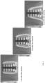
FIG. 3 is a side view of an exemplary refrigerated display cabinet and the air temperature distribution surrounding the cabinet in response to opening of the doors of the refrigerated display cabinet; -
FIG. 4 is a top perspective view of an exemplary refrigerated display cabinet including a plurality of baffles; -
FIG. 5 is a bottom perspective view of an exemplary baffle; and -
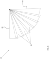
FIG. 6 is a plan view of an exemplary baffle in an extended configuration. - A detailed description of one or more embodiments of the disclosed apparatus and method are presented herein by way of exemplification and not limitation with reference to the Figures.
- With reference now to
FIGS. 1 and2 , an exemplary refrigerateddisplay cabinet 20 is illustrated. As shown, thecabinet 20 includes acabinet body 22 having abottom 24, arear wall 26, a ceiling orroof 28, andside walls space 34 for displaying goods is located between thebottom 24,rear wall 26,ceiling 28, andside walls front side 36 of thecabinet body 22 is at least onedoor 40. In the illustrated, non-limiting embodiment, thecabinet body 22 includes twodoors 40, a left door and a right door, respectively. However, it should be understood that thecabinet body 22 may have any number ofdoors 40 including a single door, three doors, or four or more doors, for example. Further, although thedoors 40 are illustrated as being at least partially transparent, embodiments where thedoors 40 and therefore the contents of the refrigerated space are not visible at an exterior of the refrigerateddisplay cabinet 20 are also contemplated herein. - The at least one
door 40 is movable between a closed position (FIG. 1 ) in which thedoor 40 seals or at least partially seals thefront side 36 of thecabinet body 22, and an open position, in which thefront side 36 of the cabinet body is open and in fluid communication with the surrounding atmosphere. As shown, thedoors 40 are configured to pivot or rotate about a respective axis X relative to thecabinet body 22 to transform between the closed position and the open position. Thedoors 40 can be operated manually, such as via one ormore handles 42 for example, or alternatively or additionally, may be operated automatically, such as via a door motor (not shown), for example. - The refrigerated
space 34 typically includes a plurality ofshelves 44 for supporting the goods displayed therein. As best shown inFIG. 2 , eachshelf 44 may be supported at a rear end by abackwall panel 46. Anair channel 48 formed between thebackwall panel 46 and therear wall 26 of thecabinet body 22 and between thebackwall panel 46 and theceiling 28 of thecabinet body 22 defines a cooled air space. In an embodiment, thebackwall 46 includes a plurality of distribution holes orperforations 50 that allow cooled air to pass from thebackwall air channel 48 into the refrigeratedspace 34. - A
heat exchanger 52 for cooling the air being provided to theshelves 44 may also be arranged within thebackwall air channel 48, such as between thebackwall panel 46 and therear wall 26 of thecabinet body 22. As shown, afan 54 is positioned immediately upstream of theheat exchanger 52 at an aft end of areturn cavity 56, between the bottommost shelf 44 and thebottom 24 of thecabinet body 22. Thefan 54 drives air from thereturn cavity 56 through theheat exchanger 52, thereby causing all of the air to be cooled while flowing into theair channel 48. While a portion of the cold air flows through thebackwall holes 50, another portion of the cold air continues to flow upward to the portion of theair channel 48 arranged adjacent to theceiling 28. A redirection feature or a Discharge Air Grille (DAG) 58 may be arranged at theceiling 28. When the air flow contacts the redirection feature or theDAG 58, the flow direction of the air is changed, such as by about 90 degrees, for example, such that the redirected cooled air is directed towards thelower shelves 44. It should be understood that the refrigerateddisplay cabinet 20 illustrated and described herein is intended as an example only, and that the refrigerateddisplay cabinet 20 may have one ormore doors 40 movable to access an internal refrigeratedspace 34. - With reference now to
FIG. 3 , when adoor 40 of thecabinet 20 is opened, such as when a user accesses the goods within the refrigeratedspace 34, a flow of conditioned air rushes from the refrigeratedspace 34 out of thecabinet 20. This cool air typically flows or spills outwardly to the ambient atmosphere near the bottom of the refrigeratedspace 34 and the lower end of thedoor 40. At the same time, a flow of ambient air typically flows or infiltrates into the interior of refrigeratedspace 34 of thecabinet 20 via the upper end of thedoor 40 and refrigeratedspace 34. A representation of the distribution of the air temperature at 1 sec, 2 sec, and 3 sec after the door opened as illustrated inFIG. 3 , clearly shows the aforementioned dynamics of ambient air infiltration into the refrigerated space and the cold air spillage into the ambient. - With reference now to
FIGS. 4 and5 , in an embodiment, to reduce or minimize the flow of warmer ambient air into the refrigeratedspace 34 and/or to restrict the flow of refrigerated air out of the refrigeratedspace 34, abaffle 60 is arranged between thedoor 40 and a portion of thecabinet body 22. When thedoor 40 is opened, thebaffle 60 is transformed from a collapsed or folded configuration to an extended configuration. In the extended configuration, thebaffle 60 is configured to form a shield that blocks or impedes the surrounding airflow into or out of the refrigeratedspace 34. - In the illustrated, non-limiting embodiment, a
first end 62 of thebaffle 60 is mounted to aninterior surface 64 of thedoor 40, such as at or near anupper end 66 of thedoor 40. In embodiments where thedoor 40 has a glass panel, thefirst end 62 may of thebaffle 60 may be mounted to one or both of the glass panel and the frame of thedoor 40 supporting the glass panel. As shown, the second,opposite end 68 of thebaffle 60 is mounted to an adjacent portion of thecabinet body 22, such as to a surface of aheader 70 for example. Thedoor 40, when closed, may be in overlapping arrangement with the portion of theheader 70 to which thebaffle 60 is mounted such that thefirst end 62 and thesecond end 68 of thebaffle 60 are generally arranged within a horizontal plane. However, thesecond end 68 of thebaffle 60 may be mounted to another portion of thecabinet 20 and/or thebaffle 60 may be mounted with another orientation. - Although the
baffle 60 is illustrated and described herein as being mounted adjacent to anupper end 66 of thedoor 40, it should be understood that thebaffle 60 may be alternatively or additionally mounted between aninterior surface 64 of thedoor 40, such as near a lower end of thedoor 40, and an adjacent surface of thecabinet body 22. - The
baffle 60 may have any suitable shape. For example, thebaffle 60 may be generally rectangular, or alternatively, may be at least partially circular in shape. As shown, a side or edge 72 of thebaffle 60 is generally arranged within the corner formed between thecabinet body 22 and thedoor 40 in the open position. In an embodiment, thebaffle 60 extends over a substantial entirety of the width of thedoor 40. However, in other embodiments, thebaffle 60 may extend over only a portion of the width of thedoor 40. In embodiments where thesecond end 68 of the baffle is mounted to a front surface of theheader 70 such that thebaffle 60 is arranged directly between thecabinet body 22 and theclosed door 40, the thickness of thebaffle 60 when collapsed must be small enough such that thedoor 40 is still able to form a seal with thecabinet body 22 when thedoor 40 is closed. - The
baffle 60 may be formed from any material that is impervious to an airflow. In an embodiment, thebaffle 60 has resilient properties. For example, thebaffle 60 is configured to stretch to the extended configuration when thedoor 40 is open and is configured to collapse onto itself when thedoor 40 is closed. By using abaffle 60 that is configured to collapse onto itself, thebaffle 60 will not sag (at least not substantially) relative to thedoor 40 to block visibility through theclosed door 40. It should be appreciated that normal wear and tear may cause thebaffle 60 to sag over time. In an embodiment, the resilience necessary to effectively transform thebaffle 60 between the extended configuration and the collapsed configuration is achieved by forming at least one fold in the material of thebaffle 60. Accordingly, when collapsed, the material of the baffle is folded onto itself via the one or more folds, and when the door is opened, the material of the baffle is unfolded. In the illustrated, non-limiting embodiment, thebaffle 60 has an accordion-like configuration including a plurality of substantially identical folds. Thebaffle 60 may be formed from a single layer of material, or alternatively, may include a plurality of layers of material, such as an overlapping first layer and second layer for example. In embodiments including a plurality of layers, thebaffle 60 may have a honeycomb or diamond like shape, similar to that used in cellular blinds. However, it should be understood that thebaffle 60 may have any suitable configuration. - In another embodiment, as shown in
FIG. 6 , thebaffle 60 includes a plurality ofpieces 80 formed from a rigid or semi-rigid material. As shown, the plurality ofpieces 80 are configured to telescope relative to one another, such as about an axis Y for example, to form a shield between thedoor 40 and thecabinet 20. In such embodiments, thesecond end 68 of thebaffle 60 may be mounted at an underside of theheader 70 of thecabinet body 22. - A
refrigerated display cabinet 20 having abaffle 60 as described herein block the flow of air at the top or bottom of thedoor 40 when opened. Accordingly, inclusion of at least onebaffle 60 will minimize the ambient air infiltration into the coldrefrigerated space 34 of thecabinet 20, and the refrigerated cold air from spilling outside of the refrigeratedspace 34 into the ambient atmosphere thereby reducing the cabinet air curtain disturbance. This will not only improve the temperature stability of the goods within the refrigeratedspace 34, but will also reduce the energy consumption of thecabinet 20. - The term "about" is intended to include the degree of error associated with measurement of the particular quantity based upon the equipment available at the time of filing the application.
- The terminology used herein is for the purpose of describing particular embodiments only and is not intended to be limiting of the present invention. As used herein, the singular forms "a", "an" and "the" are intended to include the plural forms as well, unless the context clearly indicates otherwise. It will be further understood that the terms "comprises" and/or "comprising," when used in this specification, specify the presence of stated features, integers, steps, operations, elements, and/or components, but do not preclude the presence or addition of one or more other features, integers, steps, operations, element components, and/or groups thereof.
- While the present invention has been described with reference to an exemplary embodiment or embodiments, it will be understood by those skilled in the art that various changes may be made and equivalents may be substituted for elements thereof without departing from the scope of the present invention as defined by the claims. Therefore, it is intended that the present invention not be limited to the particular embodiment disclosed as the best mode contemplated for carrying out this present invention, but that the present invention will include all embodiments falling within the scope of the claims.
Claims (15)
- A refrigerated display cabinet (20) comprising:a cabinet body (22);a refrigerated space (34) arranged within an interior of the cabinet body;a door (40) operably coupled to the cabinet body to selectively seal the refrigerated space, the door being movable between a closed position and an open position; anda baffle (60) operably coupled to the door and movable between an extended configuration, wherein when the door is in the open position, the baffle is in the extended configuration and is configured to block a flow of air relative to the refrigerated space.
- The refrigerated display cabinet of claim 1, wherein the door (40) is rotatable about an axis (X) between the closed position and the open position.
- The refrigerated display cabinet of claim 1 or claim 2, wherein the baffle (60) is arranged adjacent to an upper end of the refrigerated space (34); or
wherein the baffle (60) is arranged adj acent to a lower end of the refrigerated space (34). - The refrigerated display cabinet of any preceding claim, wherein the baffle (60) has a first end (62) and a second end (68), the first end of the baffle being affixed to the door (40), and the second end of the baffle being affixed to the cabinet body (22).
- The refrigerated display cabinet of claim 4, wherein the second end (68) of the baffle (60) is mounted to a portion of the cabinet body (22) in overlapping arrangement with the door (40) when the door is in the closed position;
or
wherein the cabinet body (22) includes a header (70) and the second end (68) of the baffle (60) is mounted at an underside of the header. - The refrigerated display cabinet of any preceding claim, wherein the baffle (60) has resilient properties.
- The refrigerated display cabinet of claim 6, wherein the baffle (60) includes at least one fold; preferably wherein the baffle (60) includes an accordion-like configuration.
- The refrigerated display cabinet of any of claims 1 to 6, wherein the baffle (60) comprises a plurality of layers (80) of material.
- The refrigerated display cabinet of any preceding claim, wherein the baffle (60) is formed from a material that is impervious to air.
- A method of stabilizing a temperature within a refrigerated display cabinet (20), the method comprising:opening a door (40) of the refrigerated display cabinet (20); andblocking a flow of air relative to a refrigerated space (34) of the refrigerated display cabinet.
- The method of claim 10, wherein blocking the flow of air relative to the refrigerated space (34) comprises blocking a flow of ambient air into the refrigerated space.
- The method of claim 10 or claim 11, wherein blocking the flow of air relative to the refrigerated space (34) comprises blocking a flow of conditioned air out of the refrigerated space.
- The method of any of claims 10 to 12, wherein blocking the flow of air relative to the refrigerated space (34) comprises extending a baffle (60) operably coupled to the door (40).
- The method of claim 13, wherein extending the baffle (60) operably coupled to the door (40) comprises unfolding the baffle;
or
wherein extending the baffle (60) operably coupled to the door (40) comprises telescoping a plurality of pieces (80) of the baffle relative to one another. - The method of claim 13 or claim 14, comprisingclosing the door (40); andcollapsing the baffle (60) at at least one fold of the baffle.
Applications Claiming Priority (1)
| Application Number | Priority Date | Filing Date | Title |
|---|---|---|---|
| US202163285797P | 2021-12-03 | 2021-12-03 |
Publications (1)
| Publication Number | Publication Date |
|---|---|
| EP4190208A1 true EP4190208A1 (en) | 2023-06-07 |
Family
ID=84369542
Family Applications (1)
| Application Number | Title | Priority Date | Filing Date |
|---|---|---|---|
| EP22210951.4A Withdrawn EP4190208A1 (en) | 2021-12-03 | 2022-12-01 | Refrigerated display cabinet foldable baffles |
Country Status (3)
| Country | Link |
|---|---|
| US (1) | US20230172371A1 (en) |
| EP (1) | EP4190208A1 (en) |
| CN (1) | CN116211106A (en) |
Families Citing this family (1)
| Publication number | Priority date | Publication date | Assignee | Title |
|---|---|---|---|---|
| CN118149521B (en) * | 2024-04-25 | 2025-06-20 | 青岛海德立餐饮设备股份有限公司 | An energy-saving freezer with moisture-proof inner compartment |
Citations (3)
| Publication number | Priority date | Publication date | Assignee | Title |
|---|---|---|---|---|
| US4537040A (en) * | 1981-04-24 | 1985-08-27 | Tyler Refrigeration Corporation | Automated energy conserving cover for refrigerated cabinet access openings |
| KR19980043703U (en) * | 1996-12-26 | 1998-09-25 | 배순훈 | Refrigerator with cold insulation membrane structure |
| KR20110134568A (en) * | 2010-06-09 | 2011-12-15 | 위니아만도 주식회사 | Cold drawer with bellows for cold storage |
Family Cites Families (7)
| Publication number | Priority date | Publication date | Assignee | Title |
|---|---|---|---|---|
| US4399666A (en) * | 1981-11-09 | 1983-08-23 | Sakutori Eric M | Refrigerator cold air retaining device |
| DE29721094U1 (en) * | 1997-11-28 | 1998-01-15 | Krause, Heiko, 08525 Plauen | Horizontal discs to minimize energy loss in cooling devices |
| DE102011112491A1 (en) * | 2011-09-01 | 2013-03-07 | Egon Hübel | Energy-saving device for household refrigerator, has exchange breaker mounted in refrigerator and displaceable such that exchange breaker disrupts and restrains cold air out-flowing from refrigerator inner space along downward direction |
| DE102011112493A1 (en) * | 2011-09-01 | 2013-03-07 | Egon Hübel | Device for saving energy of cooling device, particularly domestic refrigerator, comprises exchangeable cover, which is displaceable such that cooling air flowing downwards from refrigerator inner chamber is interrupted when door is opened |
| WO2018094415A1 (en) * | 2016-11-21 | 2018-05-24 | eXClaim IP, LLC | Environmental sleeve for portable electronic devices |
| US10045638B2 (en) * | 2016-11-28 | 2018-08-14 | Anthony, Inc. | Thermal frame |
| US20180202708A1 (en) * | 2017-01-17 | 2018-07-19 | Zihan Chen | Systems, Devices, and/or Methods for Managing Refrigerator Spillage |
-
2022
- 2022-11-30 US US18/072,360 patent/US20230172371A1/en not_active Abandoned
- 2022-12-01 EP EP22210951.4A patent/EP4190208A1/en not_active Withdrawn
- 2022-12-02 CN CN202211535056.8A patent/CN116211106A/en active Pending
Patent Citations (3)
| Publication number | Priority date | Publication date | Assignee | Title |
|---|---|---|---|---|
| US4537040A (en) * | 1981-04-24 | 1985-08-27 | Tyler Refrigeration Corporation | Automated energy conserving cover for refrigerated cabinet access openings |
| KR19980043703U (en) * | 1996-12-26 | 1998-09-25 | 배순훈 | Refrigerator with cold insulation membrane structure |
| KR20110134568A (en) * | 2010-06-09 | 2011-12-15 | 위니아만도 주식회사 | Cold drawer with bellows for cold storage |
Also Published As
| Publication number | Publication date |
|---|---|
| US20230172371A1 (en) | 2023-06-08 |
| CN116211106A (en) | 2023-06-06 |
Similar Documents
| Publication | Publication Date | Title |
|---|---|---|
| EP3804575B1 (en) | System comprising a display unit for storing and displaying food products, and multiple shelves, and method for storing and displaying food products in a display unit | |
| JP2011163574A (en) | Showcase | |
| US20230172371A1 (en) | Refrigerated display cabinet foldable baffles | |
| JPH11257830A (en) | Open showcase | |
| WO2004079281A2 (en) | Conditioned vestibule for a cold storage doorway | |
| US20170020308A1 (en) | Merchandiser | |
| US2826046A (en) | Refrigerated display case | |
| JP2017029604A (en) | Low-temperature showcase | |
| EP3843590B1 (en) | Cooler for beverage and food products | |
| JP2002272570A (en) | Flower showcase | |
| JP6181570B2 (en) | Showcase | |
| CN102727010B (en) | Showcase | |
| JP3950982B2 (en) | Refrigerated showcase | |
| NL2023983B1 (en) | System comprising a display unit for storing and displaying food products, and multiple shelves, and use of such a system | |
| NL2023985B1 (en) | System comprising a display unit for storing and displaying food products, and multiple shelves, and method for storing and displaying food products in a display unit | |
| JP6678330B2 (en) | Showcase | |
| JPH07218093A (en) | Open display case | |
| NL2023984B1 (en) | System comprising a display unit for storing and displaying food products, and multiple shelves, and method for storing and displaying refrigerated food products in a display unit | |
| JP3045381B2 (en) | Flat open showcase | |
| JP6241880B2 (en) | Open showcase | |
| JPH10274472A (en) | Showcase | |
| JP3094388B2 (en) | Flat open showcase | |
| JP2007330463A (en) | Showcase | |
| JPH11346878A (en) | Showcase | |
| WO2015118842A1 (en) | Low-temperature showcase |
Legal Events
| Date | Code | Title | Description |
|---|---|---|---|
| PUAI | Public reference made under article 153(3) epc to a published international application that has entered the european phase |
Free format text: ORIGINAL CODE: 0009012 |
|
| STAA | Information on the status of an ep patent application or granted ep patent |
Free format text: STATUS: THE APPLICATION HAS BEEN PUBLISHED |
|
| AK | Designated contracting states |
Kind code of ref document: A1 Designated state(s): AL AT BE BG CH CY CZ DE DK EE ES FI FR GB GR HR HU IE IS IT LI LT LU LV MC ME MK MT NL NO PL PT RO RS SE SI SK SM TR |
|
| STAA | Information on the status of an ep patent application or granted ep patent |
Free format text: STATUS: REQUEST FOR EXAMINATION WAS MADE |
|
| 17P | Request for examination filed |
Effective date: 20231207 |
|
| RBV | Designated contracting states (corrected) |
Designated state(s): AL AT BE BG CH CY CZ DE DK EE ES FI FR GB GR HR HU IE IS IT LI LT LU LV MC ME MK MT NL NO PL PT RO RS SE SI SK SM TR |
|
| GRAP | Despatch of communication of intention to grant a patent |
Free format text: ORIGINAL CODE: EPIDOSNIGR1 |
|
| STAA | Information on the status of an ep patent application or granted ep patent |
Free format text: STATUS: GRANT OF PATENT IS INTENDED |
|
| RIC1 | Information provided on ipc code assigned before grant |
Ipc: F25D 23/02 20060101ALI20250224BHEP Ipc: A47F 3/04 20060101AFI20250224BHEP |
|
| INTG | Intention to grant announced |
Effective date: 20250310 |
|
| STAA | Information on the status of an ep patent application or granted ep patent |
Free format text: STATUS: THE APPLICATION IS DEEMED TO BE WITHDRAWN |
|
| 18D | Application deemed to be withdrawn |
Effective date: 20250711 |