EP4189948B1 - Mobile device positioner and configurable mobile device holder - Google Patents
Mobile device positioner and configurable mobile device holder Download PDFInfo
- Publication number
- EP4189948B1 EP4189948B1 EP21749910.2A EP21749910A EP4189948B1 EP 4189948 B1 EP4189948 B1 EP 4189948B1 EP 21749910 A EP21749910 A EP 21749910A EP 4189948 B1 EP4189948 B1 EP 4189948B1
- Authority
- EP
- European Patent Office
- Prior art keywords
- coupled
- mobile device
- arm
- assembly
- slider
- Prior art date
- Legal status (The legal status is an assumption and is not a legal conclusion. Google has not performed a legal analysis and makes no representation as to the accuracy of the status listed.)
- Active
Links
Images



Classifications
-
- H—ELECTRICITY
- H04—ELECTRIC COMMUNICATION TECHNIQUE
- H04M—TELEPHONIC COMMUNICATION
- H04M1/00—Substation equipment, e.g. for use by subscribers
- H04M1/02—Constructional features of telephone sets
- H04M1/04—Supports for telephone transmitters or receivers
-
- F—MECHANICAL ENGINEERING; LIGHTING; HEATING; WEAPONS; BLASTING
- F16—ENGINEERING ELEMENTS AND UNITS; GENERAL MEASURES FOR PRODUCING AND MAINTAINING EFFECTIVE FUNCTIONING OF MACHINES OR INSTALLATIONS; THERMAL INSULATION IN GENERAL
- F16M—FRAMES, CASINGS OR BEDS OF ENGINES, MACHINES OR APPARATUS, NOT SPECIFIC TO ENGINES, MACHINES OR APPARATUS PROVIDED FOR ELSEWHERE; STANDS; SUPPORTS
- F16M11/00—Stands or trestles as supports for apparatus or articles placed thereon ; Stands for scientific apparatus such as gravitational force meters
- F16M11/02—Heads
- F16M11/04—Means for attachment of apparatus; Means allowing adjustment of the apparatus relatively to the stand
-
- F—MECHANICAL ENGINEERING; LIGHTING; HEATING; WEAPONS; BLASTING
- F16—ENGINEERING ELEMENTS AND UNITS; GENERAL MEASURES FOR PRODUCING AND MAINTAINING EFFECTIVE FUNCTIONING OF MACHINES OR INSTALLATIONS; THERMAL INSULATION IN GENERAL
- F16M—FRAMES, CASINGS OR BEDS OF ENGINES, MACHINES OR APPARATUS, NOT SPECIFIC TO ENGINES, MACHINES OR APPARATUS PROVIDED FOR ELSEWHERE; STANDS; SUPPORTS
- F16M11/00—Stands or trestles as supports for apparatus or articles placed thereon ; Stands for scientific apparatus such as gravitational force meters
- F16M11/02—Heads
- F16M11/04—Means for attachment of apparatus; Means allowing adjustment of the apparatus relatively to the stand
- F16M11/041—Allowing quick release of the apparatus
-
- F—MECHANICAL ENGINEERING; LIGHTING; HEATING; WEAPONS; BLASTING
- F16—ENGINEERING ELEMENTS AND UNITS; GENERAL MEASURES FOR PRODUCING AND MAINTAINING EFFECTIVE FUNCTIONING OF MACHINES OR INSTALLATIONS; THERMAL INSULATION IN GENERAL
- F16M—FRAMES, CASINGS OR BEDS OF ENGINES, MACHINES OR APPARATUS, NOT SPECIFIC TO ENGINES, MACHINES OR APPARATUS PROVIDED FOR ELSEWHERE; STANDS; SUPPORTS
- F16M11/00—Stands or trestles as supports for apparatus or articles placed thereon ; Stands for scientific apparatus such as gravitational force meters
- F16M11/02—Heads
- F16M11/04—Means for attachment of apparatus; Means allowing adjustment of the apparatus relatively to the stand
- F16M11/06—Means for attachment of apparatus; Means allowing adjustment of the apparatus relatively to the stand allowing pivoting
- F16M11/08—Means for attachment of apparatus; Means allowing adjustment of the apparatus relatively to the stand allowing pivoting around a vertical axis, e.g. panoramic heads
-
- F—MECHANICAL ENGINEERING; LIGHTING; HEATING; WEAPONS; BLASTING
- F16—ENGINEERING ELEMENTS AND UNITS; GENERAL MEASURES FOR PRODUCING AND MAINTAINING EFFECTIVE FUNCTIONING OF MACHINES OR INSTALLATIONS; THERMAL INSULATION IN GENERAL
- F16M—FRAMES, CASINGS OR BEDS OF ENGINES, MACHINES OR APPARATUS, NOT SPECIFIC TO ENGINES, MACHINES OR APPARATUS PROVIDED FOR ELSEWHERE; STANDS; SUPPORTS
- F16M11/00—Stands or trestles as supports for apparatus or articles placed thereon ; Stands for scientific apparatus such as gravitational force meters
- F16M11/02—Heads
- F16M11/18—Heads with mechanism for moving the apparatus relatively to the stand
-
- F—MECHANICAL ENGINEERING; LIGHTING; HEATING; WEAPONS; BLASTING
- F16—ENGINEERING ELEMENTS AND UNITS; GENERAL MEASURES FOR PRODUCING AND MAINTAINING EFFECTIVE FUNCTIONING OF MACHINES OR INSTALLATIONS; THERMAL INSULATION IN GENERAL
- F16M—FRAMES, CASINGS OR BEDS OF ENGINES, MACHINES OR APPARATUS, NOT SPECIFIC TO ENGINES, MACHINES OR APPARATUS PROVIDED FOR ELSEWHERE; STANDS; SUPPORTS
- F16M11/00—Stands or trestles as supports for apparatus or articles placed thereon ; Stands for scientific apparatus such as gravitational force meters
- F16M11/20—Undercarriages with or without wheels
- F16M11/2007—Undercarriages with or without wheels comprising means allowing pivoting adjustment
- F16M11/2021—Undercarriages with or without wheels comprising means allowing pivoting adjustment around a horizontal axis
-
- F—MECHANICAL ENGINEERING; LIGHTING; HEATING; WEAPONS; BLASTING
- F16—ENGINEERING ELEMENTS AND UNITS; GENERAL MEASURES FOR PRODUCING AND MAINTAINING EFFECTIVE FUNCTIONING OF MACHINES OR INSTALLATIONS; THERMAL INSULATION IN GENERAL
- F16M—FRAMES, CASINGS OR BEDS OF ENGINES, MACHINES OR APPARATUS, NOT SPECIFIC TO ENGINES, MACHINES OR APPARATUS PROVIDED FOR ELSEWHERE; STANDS; SUPPORTS
- F16M13/00—Other supports for positioning apparatus or articles; Means for steadying hand-held apparatus or articles
- F16M13/02—Other supports for positioning apparatus or articles; Means for steadying hand-held apparatus or articles for supporting on, or attaching to, an object, e.g. tree, gate, window-frame, cycle
- F16M13/022—Other supports for positioning apparatus or articles; Means for steadying hand-held apparatus or articles for supporting on, or attaching to, an object, e.g. tree, gate, window-frame, cycle repositionable
-
- G—PHYSICS
- G01—MEASURING; TESTING
- G01R—MEASURING ELECTRIC VARIABLES; MEASURING MAGNETIC VARIABLES
- G01R29/00—Arrangements for measuring or indicating electric quantities not covered by groups G01R19/00 - G01R27/00
- G01R29/08—Measuring electromagnetic field characteristics
- G01R29/0864—Measuring electromagnetic field characteristics characterised by constructional or functional features
- G01R29/0871—Complete apparatus or systems; circuits, e.g. receivers or amplifiers
-
- H—ELECTRICITY
- H04—ELECTRIC COMMUNICATION TECHNIQUE
- H04B—TRANSMISSION
- H04B1/00—Details of transmission systems, not covered by a single one of groups H04B3/00 - H04B13/00; Details of transmission systems not characterised by the medium used for transmission
- H04B1/38—Transceivers, i.e. devices in which transmitter and receiver form a structural unit and in which at least one part is used for functions of transmitting and receiving
- H04B1/3827—Portable transceivers
- H04B1/3877—Arrangements for enabling portable transceivers to be used in a fixed position, e.g. cradles or boosters
-
- H—ELECTRICITY
- H04—ELECTRIC COMMUNICATION TECHNIQUE
- H04M—TELEPHONIC COMMUNICATION
- H04M1/00—Substation equipment, e.g. for use by subscribers
- H04M1/02—Constructional features of telephone sets
- H04M1/0202—Portable telephone sets, e.g. cordless phones, mobile phones or bar type handsets
- H04M1/026—Details of the structure or mounting of specific components
-
- H—ELECTRICITY
- H04—ELECTRIC COMMUNICATION TECHNIQUE
- H04M—TELEPHONIC COMMUNICATION
- H04M1/00—Substation equipment, e.g. for use by subscribers
- H04M1/24—Arrangements for testing
-
- F—MECHANICAL ENGINEERING; LIGHTING; HEATING; WEAPONS; BLASTING
- F16—ENGINEERING ELEMENTS AND UNITS; GENERAL MEASURES FOR PRODUCING AND MAINTAINING EFFECTIVE FUNCTIONING OF MACHINES OR INSTALLATIONS; THERMAL INSULATION IN GENERAL
- F16M—FRAMES, CASINGS OR BEDS OF ENGINES, MACHINES OR APPARATUS, NOT SPECIFIC TO ENGINES, MACHINES OR APPARATUS PROVIDED FOR ELSEWHERE; STANDS; SUPPORTS
- F16M2200/00—Details of stands or supports
- F16M2200/06—Arms
- F16M2200/066—Arms being part of the head
Definitions
- Various features relate to mobile device holders and positioners.
- Mobile devices are tested in order to confirm and/or validate that the mobile devices perform as designed. For example, mobile devices are tested to determine and calibrate the radio frequency (RF) performance of the mobile devices.
- Testing mobile devices includes testing how well an antenna of a mobile device transmits and/or receives signals. There is an ongoing need to provide devices and/or components that are used in testing mobile devices, so that the devices and/or components do not interfere in the transmission and reception of signals to and from an antenna of a mobile device.
- WO 2015/059508 A1 relates to a phone holder for a mobile phone testing apparatus which comprises at least a base plate, a rest structure on the base plate for supporting a mobile phone, at least one block for contacting a mobile phone's narrow side, wherein the at least one block is moveably attached to the base plate, thereby enabling adapting the position of the block to a mo-bile phone being supported by said rest, and clamping means for releasable fixing the at least one first block in said position can be configured for securely holding almost any mobile phone model.
- the mobile device holder includes a body having a plurality of cavities.
- the mobile device holder includes a first assembly, a second assembly, and a third assembly.
- the first assembly is coupled to the body.
- the first assembly is configurable to be coupled to different portions of the body.
- the first assembly includes a first arm configured to be coupled to the body, a first slider coupled to the first arm, where the first slider is configured to move along the first arm, a first cap coupled to the first arm, and a first screw coupled to the first cap, where the first screw is configured to move the first slider along the first arm and towards the body.
- the second assembly is coupled to the body.
- the second assembly is configurable to be coupled to different portions of the body.
- the second assembly includes a second arm configured to be coupled to the body, a second slider coupled to the second arm, where the second slider is configured to move along the second arm, a second cap coupled to the second arm, and a second screw coupled to the second cap, where the second screw is configured to move the second slider along the second arm and towards the body.
- the third assembly is coupled to the body.
- the third assembly is configurable to be coupled to different portions of the body.
- the third assembly includes a third arm configured to be coupled to the body, a third slider coupled to the third arm, where the third slider is configured to move along the third arm, a third cap coupled to the third arm, and a third screw coupled to the third cap, where the third screw is configured to move the third slider along the third arm and towards the body.
- a mobile device positioner that includes a base, a first frame coupled to the base, a first component coupled to the first frame, where the first component is configured to rotate a component along a first plane, a second frame coupled to the first component, a second component coupled to the second frame, where the second component configured to rotate a component along a second plane, and a mobile device holder coupled to the second component.
- the mobile device holder includes a body having a plurality of cavities.
- the mobile device holder includes a first assembly, a second assembly, and a third assembly.
- the first assembly is coupled to the body.
- the first assembly is configurable to be coupled to different portions of the body.
- the first assembly includes a first arm configured to be coupled to the body, a first slider coupled to the first arm, where the first slider is configured to move along the first arm, a first cap coupled to the first arm, and a first screw coupled to the first cap, where the first screw is configured to move the first slider along the first arm and towards the body.
- the second assembly is coupled to the body. The second assembly is configurable to be coupled to different portions of the body.
- the second assembly includes a second arm configured to be coupled to the body, a second slider coupled to the second arm, where the second slider is configured to move along the second arm, a second cap coupled to the second arm, and a second screw coupled to the second cap, where the second screw is configured to move the second slider along the second arm and towards the body.
- the third assembly is coupled to the body.
- the third assembly is configurable to be coupled to different portions of the body.
- the third assembly includes a third arm configured to be coupled to the body, a third slider coupled to the third arm, where the third slider is configured to move along the third arm, a third cap coupled to the third arm, and a third screw coupled to the third cap, where the third screw is configured to move the third slider along the third arm and towards the body.
- the present disclosure describes a mobile device holder and a positioner.
- the positioner may be a manual positioner or a motorized positioner.
- the positioner may include a mobile device holder.
- the mobile device holder may be a configurable mobile device holder.
- the mobile device holder includes a body having a plurality of cavities.
- the mobile device holder includes a first assembly, a second assembly, and a third assembly.
- the first assembly is coupled to the body.
- the first assembly is configurable to be coupled to different portions of the body.
- the first assembly includes a first arm configured to be coupled to the body, a first slider coupled to the first arm, where the first slider is configured to move along the first arm, a first cap coupled to the first arm, and a first screw coupled to the first cap, where the first screw is configured to move the first slider along the first arm and towards the body.
- the second assembly is coupled to the body. The second assembly is configurable to be coupled to different portions of the body.
- the second assembly includes a second arm configured to be coupled to the body, a second slider coupled to the second arm, where the second slider is configured to move along the second arm, a second cap coupled to the second arm, and a second screw coupled to the second cap, where the second screw is configured to move the second slider along the second arm and towards the body.
- the third assembly is coupled to the body.
- the third assembly is configurable to be coupled to different portions of the body.
- the third assembly includes a third arm configured to be coupled to the body, a third slider coupled to the third arm, where the third slider is configured to move along the third arm, a third cap coupled to the third arm, and a third screw coupled to the third cap, where the third screw is configured to move the third slider along the third arm and towards the body.
- the mobile device holder may include a fourth assembly.
- the mobile device holder is configurable to hold mobile devices of various sizes and shapes. Different mobile devices may have different numbers of antennas and these antennas may be located in different parts of the mobile devices.
- the first, second, and third assemblies may be positioned and coupled to different portions of the body so as to not interfere with the various antennas of different mobile devices.
- FIG. 1 illustrates a view of a mobile device holder 100.
- the mobile device holder 100 may be a configurable mobile device holder.
- the mobile device holder 100 is configured to hold and/or couple to mobile devices of various shapes and/or sizes.
- the mobile device holder 100 includes moveable and/or configurable components that can be located in different locations so as to not interfere with antennas of a mobile device.
- the various components are made of non-metallic materials so as to no affect signals (e.g., radio frequency (RF) signal, 5G RF millimeter wave signal) coming to and from the antennas of the mobile devices.
- RF radio frequency
- the mobile device holder 100 includes a body 110 having a plurality of cavities 112 and a plurality of cavities 114.
- the plurality of cavities 112 may be located through various surfaces of the body 110.
- the plurality of cavities 114 may be located through various surfaces of the body 110.
- the mobile device holder 100 includes a first assembly 101, a second assembly 102, a third assembly 103 and a fourth assembly 104.
- the first assembly 101 is coupled to a first portion of the body 110.
- the first assembly 101 is configurable to be coupled to different portions of the body 110.
- the first assembly 101 includes a first arm 120a, a fastener 130a, a first slider 140a, a first cap 150a, a fastener 160a, and a first screw 170a.
- the first arm 120a is configured to be coupled to the body 110.
- the fastener 130a may be used to couple the first arm 120a to a first portion of the body 110.
- the fastener 130a may extend through a cavity in the first arm 120a and a first cavity from the plurality of cavities 112 of the body 110.
- the first slider 140a is coupled to the first arm 120a.
- the first slider 140a is configured to move along the first arm 120a.
- the first slider 140a is configured to be able to move back and forth along a length of the first arm 120a.
- the first cap 150a is coupled to an end of the first arm 120a.
- the fastener 160a may be used to couple the first cap 150a to the first arm 120a.
- the first screw 170a is coupled to the first cap 150a.
- the first screw 170a is configured to move the first slider 140a along the first arm 120a and towards the body 110 and/or away from the first cap 150a. Turning the first screw 170a may move the first slider 140a towards the body 110.
- the second assembly 102 is coupled to a second portion of the body 110.
- the second assembly 102 is configurable to be coupled to different portions of the body 110.
- the second assembly 102 includes a second arm 120b, a fastener 130b, a second slider 140b, a second cap 150b, a fastener 160b, and a second screw 170b.
- the second arm 120b is configured to be coupled to the body 110.
- the fastener 130b may be used to couple the second arm 120b to a second portion of the body 110.
- the fastener 130b may extend through a cavity in the second arm 120b and a second cavity from the plurality of cavities 112 of the body 110.
- the second slider 140b is coupled to the second arm 120b.
- the second slider 140b is configured to move along the second arm 120b.
- the second slider 140b is configured to be able to move back and forth along a length of the second arm 120b.
- the second cap 150b is coupled to an end of the second arm 120b.
- the fastener 160b may be used to couple the second cap 150b to the second arm 120b.
- the second screw 170b is coupled to the second cap 150b.
- the second screw 170b is configured to move the second slider 140b along the second arm 120b and towards the body 110 and/or away from the second cap 150b. Turning the second screw 170b may move the second slider 140b towards the body 110.
- the third assembly 103 is coupled to a third portion of the body 110.
- the third assembly 103 is configurable to be coupled to different portions of the body 110.
- the third assembly 103 includes a third arm 120c, a fastener 130c, a third slider 140c, a third cap 150c, a fastener 160c, and a third screw 170c.
- the third arm 120c is configured to be coupled to the body 110.
- the fastener 130c may be used to couple the third arm 120c to a third portion of the body 110.
- the fastener 130c may extend through a cavity in the third arm 120c and a third cavity from the plurality of cavities 112 of the body 110.
- the third slider 140c is coupled to the third arm 120c.
- the third slider 140c is configured to move along the third arm 120c.
- the third slider 140c is configured to be able to move back and forth along a length of the third arm 120c.
- the third cap 150c is coupled to an end of the third arm 120c.
- the fastener 160c may be used to couple the third cap 150c to the third arm 120c.
- the third screw 170c is coupled to the third cap 150c.
- the third screw 170c is configured to move the third slider 140c along the third arm 120c and towards the body 110 and/or away from the third cap 150c. Turning the third screw 170c may move the third slider 140c towards the body 110.
- the fourth assembly 104 is coupled to a fourth portion of the body 110.
- the fourth assembly 104 is configurable to be coupled to different portions of the body 110.
- the fourth assembly 104 includes a fourth arm 120d, a fastener 130d, a fourth slider 140d, a fourth cap 150d, a fastener 160d, and a fourth screw 170d.
- the fourth arm 120d is configured to be coupled to the body 110.
- the fastener 130d may be used to couple the fourth arm 120d to a fourth portion of the body 110.
- the fastener 130d may extend through a cavity in the fourth arm 120d and a fourth cavity from the plurality of cavities 112 of the body 110.
- the fourth slider 140d is coupled to the fourth arm 120d.
- the fourth slider 140d is configured to move along the fourth arm 120d.
- the fourth slider 140d is configured to be able to move back and forth along a length of the fourth arm 120d.
- the fourth cap 150d is coupled to an end of the fourth arm 120d.
- the fastener 160d may be used to couple the fourth cap 150d to the fourth arm 120d.
- the fourth screw 170d is coupled to the fourth cap 150d.
- the fourth screw 170d is configured to move the fourth slider 140d along the fourth arm 120d and towards the body 110 and/or away from the fourth cap 150d. Turning the fourth screw 170d may move the fourth slider 140d towards the body 110.
- caps may be coupled to different portions of the arm and is not limited to being coupled to an end portion of the arm. More detailed examples of an arm, a slider and a cap are illustrated and described below in at least FIGS. 6-11 .
- the materials of the various components may be non-metallic and radio frequency (RF) transparent (e.g., 5G RF millimeter wave transparent).
- RF radio frequency
- a material that is RF transparent means that a RF field can penetrate the material with little or no heating of the material.
- the body 110, the first assembly 101, the second assembly 102, the third assembly 103 and/or the fourth assembly 104 may include at least one non-metallic material.
- the body 110, the first assembly 101, the second assembly 102, the third assembly 103 and/or the fourth assembly 104 may be free of a metallic material.
- Examples of materials that may be used for the various components of the mobile device holder include ErtalytePET-P, polycarbonate, Rohacell High Frequency (RohacellHF), nylon, phenolic resin, Peek, and/or combinations thereof.
- ErtalytePET-P is a semi-crystalline thermoplastic polyester that has good dimensional stability, coupled with excellent wear resistance, low coefficient of friction and high strength. This material may be used where high loads or wear resistance between moving parts is desired.
- Polycarbonate is a clear material that has a combination of good machineability, strength and RF transparency (e.g., 5G RF millimeter wave signal transparency).
- RohacellHF has very good RF transparency (e.g., 5G RF millimeter wave signal transparency), but has poor strength and machinability.
- Peek chemically known as Polyetheretherketone is used when the fasteners are used under hi-strength or constant reuse situations.
- Nylon may be used in static situations. Compared to Peek, Nylon is extremely cost effective, but Nylon swells (and stretches) due to humidity. Nylon may not be suitable in hi-reuse or strength conditions. Phenolic Resin (which is a fiberglass) is stronger than Nylon, won't absorb moisture and possesses excellent thermal properties.
- the body 110, the arms (e.g., first arm 120a, second arm 120b, third arm 120c, fourth arm 120d), and the caps (e.g., first cap 150a, second cap 150b, third cap 150c, fourth cap 150d) may include polycarbonate.
- the sliders e.g., first slider 140a, second slider 140b, third slider 140c, fourth slider 140d
- the screws e.g., first screw 170a, second screw 170b, third screw 170c, fourth screw 170d
- fasteners e.g., 130a, 130b, 130c, 130d, 160a, 160b, 160c, 160d
- any of the components of the mobile device holder 100 may include any of the materials described above, including combinations of the materials.
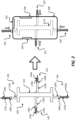
- FIG. 2 illustrates a view of how a mobile device may be coupled to a mobile device holder.
- FIG. 2 illustrates a configuration of the mobile device holder 100 that is coupled to a mobile device 200.
- the mobile device 200 includes a first antenna 202, a second antenna 204, and a third antenna 206.
- One or more of the antennas may be configured to transmit and receive cellular signals (e.g., 2G, 3G, 4G and/or 5G signals) and/or wireless signals (e.g., WIFI signals).
- cellular signals e.g., 2G, 3G, 4G and/or 5G signals
- wireless signals e.g., WIFI signals
- the mobile device 200 may be coupled to the mobile device holder 100 with the front side or the back side of the mobile device 200 facing the mobile device holder 100.
- the various assemblies e.g., 101, 102, 103, 104 are coupled to the body 110, such that the assemblies are not located over and/or near the antennas. For example, in the example of FIG.
- the first assembly 101 is coupled to a middle portion of a first side of the body 110
- the second assembly 102 is coupled to a middle portion of a second side of the body 110
- the third assembly 103 is coupled to an upper left portion of the body 110
- the fourth assembly 104 is coupled to a bottom portion of the body 110.
- the first screw 170a may be turned, which pushes the first slider 140a towards the left side of the mobile device 200.
- the second screw 170b may be turned, which pushes the second slider 140b towards the right side of the mobile device 200.
- the third screw 170c may be turned, which pushes the third slider 140c towards the top side of the mobile device 200.
- the fourth screw 170d may be turned, which pushes the fourth slider 140d towards the bottom side of the mobile device 200.
- the combination of the body 110, the first assembly 101, the second assembly 102, the third assembly 103 and the fourth assembly 104 holds and clamps the mobile device 200 in place, so that the mobile device 200 remains fixed relative to the body 110 and/or the mobile device holder 100.
- FIG. 3 illustrates a view of how a mobile device may be coupled to a mobile device holder.
- FIG. 3 illustrates another configuration of the mobile device holder 100 that is coupled to a mobile device 300.
- the mobile device 300 includes a first antenna 302, a second antenna 304, and a third antenna 306.
- One or more of the antennas may be configured to transmit and receive cellular signals (e.g., 2G, 3G, 4G and/or 5G signals) and/or wireless signals (e.g., WIFI signals).
- the mobile device 300 has a different size and shape than the mobile device 200. Additionally, the antennas of the mobile device 300 are located in different locations than the antennas of the mobile device 200.
- the first assembly 101, the second assembly 102, the third assembly 103 and the fourth assembly 104 are coupled to different portions of the body 110 than how the assemblies are coupled in FIG. 2 .
- the first assembly 101 is coupled to an upper portion of a first side of the body 110
- the second assembly 102 is coupled to a lower portion of a second side of the body 110
- the third assembly 103 is coupled to an upper right portion of the body 110
- the fourth assembly 104 is coupled to a bottom right portion of the body 110.
- the combination of the body 110, the first assembly 101, the second assembly 102, the third assembly 103 and the fourth assembly 104 holds and clamps the mobile device 300 in place, so that the mobile device 200 remains fixed relative to the body 110 and/or the mobile device holder 100.
- FIGS. 1-3 illustrate a mobile device holder 100 with a body 110 having an I shape.
- the body 110 may have different shapes.
- FIGS. 4 and 5 illustrate mobile device holders with different bodies and assemblies.
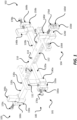
- FIG. 4 illustrates a mobile device holder 400 that includes a body 410, a first assembly 401, a second assembly 402, a third assembly 403 and a fourth assembly 404.
- the body 410 may include the plurality of cavities 112, as described for the body 110.
- the body 410 has a C shape.
- the first assembly 401, the second assembly 402, the third assembly 403 and the fourth assembly 404 are each similar to the first assembly 101, the second assembly 102, the third assembly 103 and the fourth assembly 104.
- the first assembly 401, the second assembly 402, the third assembly 403 and the fourth assembly 404 may each include similar components, such as an arm (e.g., 120a), a fastener (e.g., 130a), a slider (e.g., 140a), a cap (e.g., 150a), a fastener (e.g., 160a) and a screw (e.g., 170a).
- the assemblies may have different lengths.
- the arm of the second assembly 402 is longer than the arms of the other assemblies.
- the arm of the first assembly 401, the arm of the third assembly 403 and the arm of the fourth assembly 404 may be shorter than the arm of the second assembly 402.
- FIG. 5 illustrates a mobile device holder 500 that includes a body 510, a first assembly 501, a second assembly 502, a third assembly 503 and a fourth assembly 504.
- the body 510 may include the plurality of cavities 112, as described for the body 110.
- the body 510 has an O shape and/or a D shape.
- the first assembly 501, the second assembly 502, the third assembly 503 and the fourth assembly 504 are each similar to the first assembly 101, the second assembly 102, the third assembly 103 and the fourth assembly 104.
- first assembly 501, the second assembly 502, the third assembly 503 and the fourth assembly 504 may each include similar components, such as an arm (e.g., 120a), a fastener (e.g., 130a), a slider (e.g., 140a), a cap (e.g., 150a), a fastener (e.g., 160a) and a screw (e.g., 170a).
- the assemblies e.g., 501, 502, 503, 504 may have different lengths.
- one or more of assemblies may be fixed and not moveable.
- one or more assemblies may be coupled to the body (e.g., 110, 410, 510) in such a way that the assembly cannot be moved to a different location.
- the fourth assembly e.g., 104, 404, 504
- the arm (e.g., 120d) of the assembly may be permanently coupled to the body.
- the arm (of the fourth assembly) may be a fixed portion of the body.
- the fixed portion may be a coupling portion of the body, that is configured to provide an opposing force to a force applied by the third assembly.
- different implementations may have different coupling portions.
- the arm (e.g., 120d) may be part of the body (e.g., 110, 410, 510). This may be the case when antennas are not likely to be located in a lower portion of the mobile device.
- FIGS. 6-11 illustrate various views of the components of a mobile device holder.
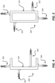
- FIGS. 6 and 7 illustrate an arm 120.
- the arm 120 includes a first cavity 600 and a second cavity 602.
- a fastener e.g., 130a
- Another fastener e.g., 160a
- the arm 120 has an L shape.
- the arm 120 may have different shapes.
- FIGS. 8-9 illustrate a slider 140.
- the slider 140 includes a cavity 800.
- the cavity 800 is used to couple the slider 140 to the arm 120.
- the slider 140 may be configured to move along the arm 120 through the cavity 800.
- the profile of the cavity 800 may match the profile cross section of the arm 120.
- FIGS. 10-11 illustrate a cap 150.
- the cap 150 includes a first cavity 1000 and a second cavity 1002.
- a fastener e.g., 160a
- a screw e.g., 170a
- a screw may be extended through the second cavity 1002 of the cap 150. Turning the screw (e.g., 170a) may move the screw, which may push the slider 140 along the arm 120.
- FIG. 12 illustrates an exemplary sequence for coupling a mobile device to a mobile device holder. It should be noted that the sequence of FIG. 12 may combine one or more stages in order to simplify and/or clarify the sequence for coupling a mobile device to a mobile device holder. FIG. 12 illustrates a mobile device 200 being coupled to a mobile device holder 100. However, the sequence of FIG. 12 may be used to couple any mobile device to any of the mobile device holders described in the disclosure. In some implementations, the order of the processes may be changed or modified.
- Stage 1 illustrates the mobile device holder 100.
- the mobile device holder 100 is a configurable mobile device holder 100.
- the mobile device holder 100 includes the first assembly 101 and the second assembly 102.
- the mobile device holder 100 may include a third assembly 103 and a fourth assembly 104, as described in FIG. 1 .
- the first assembly 101 is coupled to the body 110.
- the second assembly 102 is coupled to the body 110.
- Stage 2 illustrates a state after the mobile device 200 is positioned over the body 110.
- the mobile device 200 may be positioned with the front side or the back side of the mobile device 200 facing the body 110.
- Stage 3 illustrates a state after the first screw 170a is turned, which pushes the first slider 140a towards a side of the mobile device 200.
- the first slider 140a moves along the first arm 120a.
- Stage 3 also illustrates a state after the second screw 170b is turned, which pushes the second slider 140b towards another side of the mobile device 200.
- the second slider 140b moves along the second arm 120b.
- the first screw 170a and the second screw 170b help hold and lock the mobile device 200 in place.
- the first slider 140a and the second slider 140b have an angled surface, which helps provide a force on the mobile device 200 that pushes the mobile device 200 towards the body 110.
- third assembly 103 and the fourth assembly 104 are not shown in FIG. 12 .
- the screws of the third assembly 103 and the fourth assembly 104 may be turned in a similar fashion to secure and hold the mobile device 200.
- FIG. 13 illustrates a view of another mobile device holder 1300.
- the mobile device holder 1300 may be a configurable mobile device holder.
- the mobile device holder 1300 is configured to hold and/or couple to mobile devices of various shapes and/or sizes.
- the mobile device holder 1300 includes moveable and/or configurable components that can be located in different locations so as to not interfere with antennas of a mobile device.
- the various components are made of non-metallic materials so as to no affect signals (e.g., radio frequency (RF) signal, 5G RF millimeter wave signal) coming to and from the antennas of the mobile device.
- RF radio frequency
- the mobile device holder 1300 is similar to the mobile device holder 100, and thus includes similar components as the mobile device holder 100. However, the mobile device holder 1300 includes components with snap on coupling. In some implementations, the mobile device holder 1300 may bypass the use of one or more fasteners to couple assemblies to the body and/or caps to arms.
- the mobile device holder 1300 includes the body 1310, a first assembly 1301, a second assembly 1302, a third assembly 1303 and a fourth assembly 1304.
- the body 1310 is similar to the body 110 of FIG. 1 .
- the body 1310 includes a plurality of cavities 1312, a plurality of cavities 1314, and a plurality of cavities 1316.
- the first assembly 1301, the second assembly 1302, the third assembly 1303 and the fourth assembly 1304 may be coupled to different portions of the body 1310.
- the first assembly 1301, the second assembly 1302, the third assembly 1303 and the fourth assembly 1304 may be coupled to the body 1310 through a snap on coupling, which is further described below in at least FIGS. 14-16 .
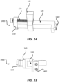
- FIGS. 14 and 15 illustrate an assembly 1400.
- the assembly 1400 may represent the first assembly 1301, the second assembly 1302, the third assembly 1303 and/or the fourth assembly 1304.
- the assembly 1400 includes an arm 120, a slider 140, a cap 150, and a screw 170.
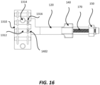
- the arm 120 includes at least one protrusion 1402.
- the at least one protrusion 1402 allows the arm 120 to securely couple to the body 1310.
- the at least one protrusion 1402 may insert in at least one cavity 1312 of the body 1310.
- the at least one protrusion 1402 may snap in and out of the at least one cavity 1312, thus enabling snap on coupling.
- Portions of the at least one protrusion 1402 may be located in the at least one cavity 1316, which holds the at least one protrusion 1402 and the corresponding arm 120 into place with the body 1310.
- the at least one protrusion 1402 may have different shapes. In one example, the at least one protrusion 1402 may have a cylindrical shape.
- the at least one protrusion 1402 may have a rigid portion and a flexible portion. When in the relaxed position, the flexible portion may have a cross section that is larger than the cross section of the rigid portion. The flexible portion of the at least one protrusion 1402 may bend inwards when inserted in a cavity so that the at least one protrusion 1402 may be inserted in the cavity.
- the flexible portion of the at least one protrusion 1402 may snap back outwards once the flexible portion passes through the cavity, which enables the at least one protrusion 1402 to couple and lock with another component.
- the cap 150 may be coupled to the arm 120 through a snap on coupling.
- the cap 150 may include protrusions similar to the protrusion 1402.
- the arm 120 may include another protrusion that may be used to couple the arm 120 to the cap 150.
- the another protrusion of the arm 120 may be similar to the at least one protrusion 1402.
- the another protrusion of the arm 120 may couple to a cavity (e.g., 1000) of the cap 150. Different assemblies may have different lengths for the arm 120.
- FIG. 16 illustrates the arm 120 coupled to the body 1310 through at least one cavity 1312 and the at least one protrusion 1402.
- the body 1310 may have different shapes and/or sizes, as described for the body 110.
- the body 1310 may include an I shape, a C shape, an O shape, a D shape and/or combination thereof.
- the caps e.g., 150, 150a, 150b, 150c, 150d
- the arms may be coupled to different portions of the arm and is not limited to being coupled to an end portion of the arm.
- FIGS. 17 and 18 illustrate various positioners that include a mobile device holder.
- the positioners may be used when testing mobile devices for RF performances.
- the mobile device positioners help position the mobile device in various positions and angles in a chamber, to test and measure how the locations of various antennas in the mobile devices may perform under different scenarios.
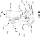
- FIG. 17 illustrates a mobile device positioner 1700.
- the mobile device positioner 1700 may be a manual mobile device positioner.
- the mobile device positioner 1700 includes a base 1710, a vertical frame 1720, a first pivot frame 1730, a pivot post 1740, a vertical arm frame 1750, a pivot mount 1760, a second pivot frame 1770, and an adapter 1780.
- the vertical frame 1720 is coupled to the base 1710.
- the first pivot frame 1730 is coupled to the vertical frame 1720 through the pivot post 1740.
- the vertical arm frame 1750 is coupled to the first pivot frame 1730.
- the pivot mount 1760 is coupled to the vertical arm frame 1750.
- the second pivot frame 1770 is coupled to the pivot mount 1760.
- the adapter 1780 is coupled to the second pivot frame 1770.
- the mobile device holder 100 is coupled to the adapter 1780.
- Fasteners may be used to couple the mobile device holder 100 to the adapter 1780.
- the fasteners may extend through cavities in the adapter 1780 and/or cavities (e.g., 114, 1314) of the mobile device holder 100.
- the mobile device 200 is coupled to the mobile device holder 100.
- the first pivot frame 1730 may rotate and/or pivot along a first plane.
- the first plane may be a vertical plane.
- the first pivot frame 1730 may rotate relative to the vertical frame 1720.
- the first pivot frame 1730 may include a calibration disk that helps indicate the angle of the rotation (e.g., vertical rotation). Rotating the first pivot frame 1730 may cause the vertical arm frame 1750 to rotate, which ultimately causes the mobile device holder 100 and the mobile device 200 to rotate as well, in a similar fashion.
- the pivot post 1740 may be used to hold the first pivot frame 1730 at a particular angle and/or rotation.
- the second pivot frame 1770 may rotate and/or pivot along a second plane.
- the second plane may be a horizontal plane.
- the second pivot frame 1770 may rotate relative to the pivot mount 1760.
- the second pivot frame 1770 may include a calibration disk that helps indicate the angle of the rotation (e.g., horizontal rotation). Rotating the second pivot frame 1770 may cause the adapter 1780 to rotate, which ultimately causes the mobile device holder 100 and the mobile device 200 to rotate as well, in a similar fashion.
- One or more fasteners may be used to hold the second pivot frame 1770 at a particular angle and/or rotation.
- the first pivot frame 1730 and the second pivot frame 1770 may be used to position the mobile device 200 at any angle and position.
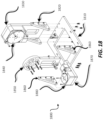
- FIG. 18 illustrates a mobile device positioner 1800.
- the mobile device positioner 1800 may be a motorized mobile device positioner.
- the mobile device positioner 1800 includes a base 1810, a frame 1820, a vertical frame 1830, a first motor 1840, a rotating frame 1850, a frame 1860, a frame 1870 and a second motor 1880.
- the frame 1820 is coupled to the base 1810.
- the vertical frame 1830 is coupled to the frame 1820.
- the first motor 1840 is coupled to the vertical frame 1830.
- the rotating frame 1850 is coupled to the first motor 1840.
- the frame 1860 is coupled to the rotating frame 1850.
- the frame 1870 is coupled to the frame 1860.
- the second motor 1880 is coupled to the frame 1870.
- the first motor 1840 and/or the second motor 1880 may each be a stepper motor and/or a rotary stage.
- the rotating frame 1850 may be a vertically rotating frame.
- the adapter 1780 may be coupled to the second motor 1880.
- the mobile device holder 100 may be coupled to the second motor 1880 directly or through the adapter 1780.
- the adapter 1780 may be coupled to the second motor 1880, and the mobile device holder 100 may be coupled to the adapter 1780.
- Fasteners may be used to couple the mobile device holder 100 to the adapter 1780.
- the fasteners may extend through cavities in the adapter 1780 and/or cavities (e.g., 114, 1314) of the mobile device holder 100.
- the mobile device 200 is coupled to the mobile device holder 100.
- the first motor 1840 is configured to rotate the rotating frame 1850 along a first plane.
- the first plane may be a vertical plane.
- the rotating frame 1850 may rotate relative to the first motor 1840 and/or the vertical frame 1830. Rotating the rotating frame 1850 may cause the mobile device holder 100 and the mobile device 200 to rotate as well, in a similar fashion.
- the second motor 1880 is configured to rotate the adapter 1780 and/or the mobile device holder 100 along a second plane.
- the second plane may be a horizontal plane.
- the adapter 1780 and/or the mobile device holder 100 may rotate relative to the second motor 1880 and/or the frame 1870. Rotating the adapter 1780 and/or the mobile device holder 100 may cause the mobile device 200 to rotate as well, in a similar fashion.
- the first motor 1840 and the second motor 1880 may be used to position the mobile device 200 at any angle and position.
- FIGS. 17 and 18 illustrate mobile device positioners with various components and/or parts. It is noted that some of these components and/or parts may be combined and/or omitted.
- the frame 1820 and the vertical frame 1830 may be the same component.
- the frame 1870 may be coupled to the rotating frame 1850 directly instead of through the frame 1860.
- the frame 1870 and the rotating frame 1850 may be the same component.
- the vertical arm frame 1750 and the pivot mount 1760 may be the same component.
- the various components and/or parts shown in FIGS. 17-18 may be mechanically coupled through various means, including fasteners and/or adhesives. In some implementations, a single component may be broken up into several components and/or parts.
- the various components and/or parts of the mobile device positioners may include the same material and/or similar materials as the mobile device holder. It is noted that mobile device positioners may include any of the mobile device holders described in the disclosure. Different implementations may use different types of fasteners.
- a fastener may include a screw, bolt and/or nut.
- a frame may include a plate.
- FIGS. 17-18 illustrate examples of mobile device positioners that includes a base (e.g., 1710, 1810), a first component coupled to the first frame, a second frame (e.g., 1750, 1760, 1850) coupled to the first component, a second component coupled to the second frame, and a mobile device holder (e.g., 100, 400, 500) coupled to the second component.
- the first component is configured to rotate a component along a first plane.
- the first component may include the first pivot frame 1730 and/or the first motor 1840.
- the first plane may include a vertical plane or a horizontal plane.
- the second component is configured to rotate a component along a second plane.
- the second component may include the second pivot frame 1770 and/or the second motor 1880.
- the second plane may include a vertical plane or a horizontal plane.
- FIGS. 1-18 One or more of the components, processes, features, and/or functions illustrated in FIGS. 1-18 may be rearranged and/or combined into a single component, process, feature or function or embodied in several components, processes, or functions. Additional elements, components, processes, and/or functions may also be added without departing from the disclosure.
- the figures in the disclosure may represent actual representations and/or conceptual representations of various parts, components, objects, devices, holders, and/or positioners. In some instances, the figures may not be to scale. In some instances, for purpose of clarity, not all components and/or parts may be shown. In some instances, the position, the location, the sizes, and/or the shapes of various parts and/or components in the figures may be exemplary. In some implementations, various components and/or parts in the figures may be optional.
- Coupled is used herein to refer to the direct or indirect coupling (e.g., mechanical coupling) between two objects. For example, if object A physically touches object B, and object B touches object C, then objects A and C may still be considered coupled to one another-even if they do not directly physically touch each other.
- the term “electrically coupled” may mean that two objects are directly or indirectly coupled together such that an electrical current (e.g., signal, power, ground) may travel between the two objects. Two objects that are electrically coupled may or may not have an electrical current traveling between the two objects.
- the use of the terms “first”, “second”, “third” and “fourth” (and/or anything above fourth) is arbitrary. Any of the components described may be the first component, the second component, the third component or the fourth component. For example, a component that is referred to a second component, may be the first component, the second component, the third component or the fourth component.
- the terms “top” and “bottom” are arbitrary. A component that is located on top may be located over a component that is located on a bottom.
- a top component may be considered a bottom component, and vice versa.
- a first component that is located "over" a second component may mean that the first component is located above or below the second component, depending on how a bottom or top is arbitrarily defined.
- a first component may be located over (e.g., above) a first surface of the second component, and a third component may be located over (e.g., below) a second surface of the second component, where the second surface is opposite to the first surface.
- a first component that is over the second component may mean that (1) the first component is over the second component, but not directly touching the second component, (2) the first component is on (e.g., on a surface of) the second component, and/or (3) the first component is in (e.g., embedded in) the second component.
- a first component that is located "in” a second component may be partially located in the second component or completely located in the second component.
Landscapes
- Engineering & Computer Science (AREA)
- General Engineering & Computer Science (AREA)
- Mechanical Engineering (AREA)
- Signal Processing (AREA)
- Computer Networks & Wireless Communication (AREA)
- Physics & Mathematics (AREA)
- Electromagnetism (AREA)
- General Physics & Mathematics (AREA)
- Telephone Set Structure (AREA)
Description
- The present application claims priority to and the benefit of Non-Provisional Application No.
17/194,171 filed in the United States Patent and Trademark Office on March 5, 2021 63/058,361 filed in the United States Patent and Trademark Office on July 29, 2020 - Various features relate to mobile device holders and positioners.
- Mobile devices are tested in order to confirm and/or validate that the mobile devices perform as designed. For example, mobile devices are tested to determine and calibrate the radio frequency (RF) performance of the mobile devices. Testing mobile devices includes testing how well an antenna of a mobile device transmits and/or receives signals. There is an ongoing need to provide devices and/or components that are used in testing mobile devices, so that the devices and/or components do not interfere in the transmission and reception of signals to and from an antenna of a mobile device. Attention is drawn to document
WO 2015/059508 A1 which relates to a phone holder for a mobile phone testing apparatus which comprises at least a base plate, a rest structure on the base plate for supporting a mobile phone, at least one block for contacting a mobile phone's narrow side, wherein the at least one block is moveably attached to the base plate, thereby enabling adapting the position of the block to a mo-bile phone being supported by said rest, and clamping means for releasable fixing the at least one first block in said position can be configured for securely holding almost any mobile phone model. - The invention is defined by the appended independent claims. Further embodiments of the invention are defined by the appended dependent claims. Various features relate to mobile device holders and positioners.
- One example provides a mobile device holder that includes a body having a plurality of cavities. The mobile device holder includes a first assembly, a second assembly, and a third assembly. The first assembly is coupled to the body. The first assembly is configurable to be coupled to different portions of the body. The first assembly includes a first arm configured to be coupled to the body, a first slider coupled to the first arm, where the first slider is configured to move along the first arm, a first cap coupled to the first arm, and a first screw coupled to the first cap, where the first screw is configured to move the first slider along the first arm and towards the body. The second assembly is coupled to the body. The second assembly is configurable to be coupled to different portions of the body. The second assembly includes a second arm configured to be coupled to the body, a second slider coupled to the second arm, where the second slider is configured to move along the second arm, a second cap coupled to the second arm, and a second screw coupled to the second cap, where the second screw is configured to move the second slider along the second arm and towards the body. The third assembly is coupled to the body. The third assembly is configurable to be coupled to different portions of the body. The third assembly includes a third arm configured to be coupled to the body, a third slider coupled to the third arm, where the third slider is configured to move along the third arm, a third cap coupled to the third arm, and a third screw coupled to the third cap, where the third screw is configured to move the third slider along the third arm and towards the body.
- Another example provides a mobile device positioner that includes a base, a first frame coupled to the base, a first component coupled to the first frame, where the first component is configured to rotate a component along a first plane, a second frame coupled to the first component, a second component coupled to the second frame, where the second component configured to rotate a component along a second plane, and a mobile device holder coupled to the second component. The mobile device holder includes a body having a plurality of cavities. The mobile device holder includes a first assembly, a second assembly, and a third assembly. The first assembly is coupled to the body. The first assembly is configurable to be coupled to different portions of the body. The first assembly includes a first arm configured to be coupled to the body, a first slider coupled to the first arm, where the first slider is configured to move along the first arm, a first cap coupled to the first arm, and a first screw coupled to the first cap, where the first screw is configured to move the first slider along the first arm and towards the body. The second assembly is coupled to the body. The second assembly is configurable to be coupled to different portions of the body. The second assembly includes a second arm configured to be coupled to the body, a second slider coupled to the second arm, where the second slider is configured to move along the second arm, a second cap coupled to the second arm, and a second screw coupled to the second cap, where the second screw is configured to move the second slider along the second arm and towards the body. The third assembly is coupled to the body. The third assembly is configurable to be coupled to different portions of the body. The third assembly includes a third arm configured to be coupled to the body, a third slider coupled to the third arm, where the third slider is configured to move along the third arm, a third cap coupled to the third arm, and a third screw coupled to the third cap, where the third screw is configured to move the third slider along the third arm and towards the body.
- Various features, nature and advantages may become apparent from the detailed description set forth below when taken in conjunction with the drawings in which like reference characters identify correspondingly throughout.
-
FIG. 1 illustrates an exemplary view of a configurable mobile device holder. -
FIG. 2 illustrates an exemplary view of a configuration of a configurable mobile device holder coupled to a mobile device. -
FIG. 3 illustrates an exemplary view of another configuration of a configurable mobile device holder coupled to a mobile device. -
FIG. 4 illustrates an exemplary view of another configurable mobile device holder. -
FIG. 5 illustrates an exemplary view of another configurable mobile device holder. -
FIG. 6 illustrates an exemplary view of an arm for a mobile device holder. -
FIG. 7 illustrates another exemplary view of an arm for a mobile device holder. -
FIG. 8 illustrates an exemplary view of a slider for a mobile device holder. -
FIG. 9 illustrates another exemplary view of a slider for a mobile device holder. -
FIG. 10 illustrates an exemplary view of a cap for a mobile device holder. -
FIG. 11 illustrates another exemplary view of a cap for a mobile device holder. -
FIG. 12 illustrates an exemplary sequence for coupling a mobile device to a configurable mobile device holder. -
FIG. 13 illustrates an exemplary view of a configurable mobile device holder with snap on coupling. -
FIG. 14 illustrates an exemplary view of an arm and slider assembly with snap on coupling for a configurable mobile device holder. -
FIG. 15 illustrates an exemplary view of an arm and slider assembly with snap on coupling for a configurable mobile device holder. -
FIG. 16 illustrates an exemplary view of an arm coupled to a body through a snap on coupling. -
FIG. 17 illustrates an exemplary view of a manual positioner with a configurable mobile device holder. -
FIG. 18 illustrates an exemplary view of a motorized positioner that may be implemented with a configurable mobile device holder. - In the following description, specific details are given to provide a thorough understanding of the various aspects of the disclosure. However, it will be understood by one of ordinary skill in the art that the aspects may be practiced without these specific details. For example, circuits may be shown in block diagrams in order to avoid obscuring the aspects in unnecessary detail. In other instances, well-known circuits, structures and techniques may not be shown in detail in order not to obscure the aspects of the disclosure.
- The present disclosure describes a mobile device holder and a positioner. The positioner may be a manual positioner or a motorized positioner. The positioner may include a mobile device holder. The mobile device holder may be a configurable mobile device holder. The mobile device holder includes a body having a plurality of cavities. The mobile device holder includes a first assembly, a second assembly, and a third assembly. The first assembly is coupled to the body. The first assembly is configurable to be coupled to different portions of the body. The first assembly includes a first arm configured to be coupled to the body, a first slider coupled to the first arm, where the first slider is configured to move along the first arm, a first cap coupled to the first arm, and a first screw coupled to the first cap, where the first screw is configured to move the first slider along the first arm and towards the body. The second assembly is coupled to the body. The second assembly is configurable to be coupled to different portions of the body. The second assembly includes a second arm configured to be coupled to the body, a second slider coupled to the second arm, where the second slider is configured to move along the second arm, a second cap coupled to the second arm, and a second screw coupled to the second cap, where the second screw is configured to move the second slider along the second arm and towards the body. The third assembly is coupled to the body. The third assembly is configurable to be coupled to different portions of the body. The third assembly includes a third arm configured to be coupled to the body, a third slider coupled to the third arm, where the third slider is configured to move along the third arm, a third cap coupled to the third arm, and a third screw coupled to the third cap, where the third screw is configured to move the third slider along the third arm and towards the body. The mobile device holder may include a fourth assembly. The mobile device holder is configurable to hold mobile devices of various sizes and shapes. Different mobile devices may have different numbers of antennas and these antennas may be located in different parts of the mobile devices. The first, second, and third assemblies may be positioned and coupled to different portions of the body so as to not interfere with the various antennas of different mobile devices.
-
FIG. 1 illustrates a view of amobile device holder 100. Themobile device holder 100 may be a configurable mobile device holder. Themobile device holder 100 is configured to hold and/or couple to mobile devices of various shapes and/or sizes. As will be further described below, themobile device holder 100 includes moveable and/or configurable components that can be located in different locations so as to not interfere with antennas of a mobile device. Moreover, the various components are made of non-metallic materials so as to no affect signals (e.g.., radio frequency (RF) signal, 5G RF millimeter wave signal) coming to and from the antennas of the mobile devices. - The
mobile device holder 100 includes abody 110 having a plurality ofcavities 112 and a plurality ofcavities 114. The plurality ofcavities 112 may be located through various surfaces of thebody 110. The plurality ofcavities 114 may be located through various surfaces of thebody 110. Themobile device holder 100 includes afirst assembly 101, asecond assembly 102, athird assembly 103 and afourth assembly 104. - The
first assembly 101 is coupled to a first portion of thebody 110. Thefirst assembly 101 is configurable to be coupled to different portions of thebody 110. Thefirst assembly 101 includes afirst arm 120a, afastener 130a, afirst slider 140a, afirst cap 150a, afastener 160a, and afirst screw 170a. Thefirst arm 120a is configured to be coupled to thebody 110. Thefastener 130a may be used to couple thefirst arm 120a to a first portion of thebody 110. Thefastener 130a may extend through a cavity in thefirst arm 120a and a first cavity from the plurality ofcavities 112 of thebody 110. Thefirst slider 140a is coupled to thefirst arm 120a. Thefirst slider 140a is configured to move along thefirst arm 120a. For example, thefirst slider 140a is configured to be able to move back and forth along a length of thefirst arm 120a. Thefirst cap 150a is coupled to an end of thefirst arm 120a. Thefastener 160a may be used to couple thefirst cap 150a to thefirst arm 120a. Thefirst screw 170a is coupled to thefirst cap 150a. Thefirst screw 170a is configured to move thefirst slider 140a along thefirst arm 120a and towards thebody 110 and/or away from thefirst cap 150a. Turning thefirst screw 170a may move thefirst slider 140a towards thebody 110. - The
second assembly 102 is coupled to a second portion of thebody 110. Thesecond assembly 102 is configurable to be coupled to different portions of thebody 110. Thesecond assembly 102 includes asecond arm 120b, afastener 130b, asecond slider 140b, asecond cap 150b, afastener 160b, and asecond screw 170b. Thesecond arm 120b is configured to be coupled to thebody 110. Thefastener 130b may be used to couple thesecond arm 120b to a second portion of thebody 110. Thefastener 130b may extend through a cavity in thesecond arm 120b and a second cavity from the plurality ofcavities 112 of thebody 110. Thesecond slider 140b is coupled to thesecond arm 120b. Thesecond slider 140b is configured to move along thesecond arm 120b. For example, thesecond slider 140b is configured to be able to move back and forth along a length of thesecond arm 120b. Thesecond cap 150b is coupled to an end of thesecond arm 120b. Thefastener 160b may be used to couple thesecond cap 150b to thesecond arm 120b. Thesecond screw 170b is coupled to thesecond cap 150b. Thesecond screw 170b is configured to move thesecond slider 140b along thesecond arm 120b and towards thebody 110 and/or away from thesecond cap 150b. Turning thesecond screw 170b may move thesecond slider 140b towards thebody 110. - The
third assembly 103 is coupled to a third portion of thebody 110. Thethird assembly 103 is configurable to be coupled to different portions of thebody 110. Thethird assembly 103 includes athird arm 120c, afastener 130c, athird slider 140c, athird cap 150c, afastener 160c, and athird screw 170c. Thethird arm 120c is configured to be coupled to thebody 110. Thefastener 130c may be used to couple thethird arm 120c to a third portion of thebody 110. Thefastener 130c may extend through a cavity in thethird arm 120c and a third cavity from the plurality ofcavities 112 of thebody 110. Thethird slider 140c is coupled to thethird arm 120c. Thethird slider 140c is configured to move along thethird arm 120c. For example, thethird slider 140c is configured to be able to move back and forth along a length of thethird arm 120c. Thethird cap 150c is coupled to an end of thethird arm 120c. Thefastener 160c may be used to couple thethird cap 150c to thethird arm 120c. Thethird screw 170c is coupled to thethird cap 150c. Thethird screw 170c is configured to move thethird slider 140c along thethird arm 120c and towards thebody 110 and/or away from thethird cap 150c. Turning thethird screw 170c may move thethird slider 140c towards thebody 110. - The
fourth assembly 104 is coupled to a fourth portion of thebody 110. Thefourth assembly 104 is configurable to be coupled to different portions of thebody 110. Thefourth assembly 104 includes afourth arm 120d, afastener 130d, afourth slider 140d, afourth cap 150d, afastener 160d, and afourth screw 170d. Thefourth arm 120d is configured to be coupled to thebody 110. Thefastener 130d may be used to couple thefourth arm 120d to a fourth portion of thebody 110. Thefastener 130d may extend through a cavity in thefourth arm 120d and a fourth cavity from the plurality ofcavities 112 of thebody 110. Thefourth slider 140d is coupled to thefourth arm 120d. Thefourth slider 140d is configured to move along thefourth arm 120d. For example, thefourth slider 140d is configured to be able to move back and forth along a length of thefourth arm 120d. Thefourth cap 150d is coupled to an end of thefourth arm 120d. Thefastener 160d may be used to couple thefourth cap 150d to thefourth arm 120d. Thefourth screw 170d is coupled to thefourth cap 150d. Thefourth screw 170d is configured to move thefourth slider 140d along thefourth arm 120d and towards thebody 110 and/or away from thefourth cap 150d. Turning thefourth screw 170d may move thefourth slider 140d towards thebody 110. - It is also noted that the caps (e.g., 150a, 150b, 150c, 150d) may be coupled to different portions of the arm and is not limited to being coupled to an end portion of the arm. More detailed examples of an arm, a slider and a cap are illustrated and described below in at least
FIGS. 6-11 . - Different implementations may use different materials for the various components of the
mobile device holder 100. The materials of the various components may be non-metallic and radio frequency (RF) transparent (e.g., 5G RF millimeter wave transparent). A material that is RF transparent (e.g., 5G RF millimeter wave signal transparent) means that a RF field can penetrate the material with little or no heating of the material. For example, thebody 110, thefirst assembly 101, thesecond assembly 102, thethird assembly 103 and/or thefourth assembly 104 may include at least one non-metallic material. Thebody 110, thefirst assembly 101, thesecond assembly 102, thethird assembly 103 and/or thefourth assembly 104 may be free of a metallic material. - Examples of materials that may be used for the various components of the mobile device holder include ErtalytePET-P, polycarbonate, Rohacell High Frequency (RohacellHF), nylon, phenolic resin, Peek, and/or combinations thereof.
- ErtalytePET-P is a semi-crystalline thermoplastic polyester that has good dimensional stability, coupled with excellent wear resistance, low coefficient of friction and high strength. This material may be used where high loads or wear resistance between moving parts is desired. Polycarbonate is a clear material that has a combination of good machineability, strength and RF transparency (e.g., 5G RF millimeter wave signal transparency). RohacellHF has very good RF transparency (e.g., 5G RF millimeter wave signal transparency), but has poor strength and machinability. Peek (chemically known as Polyetheretherketone) is used when the fasteners are used under hi-strength or constant reuse situations. Some of the benefits of peek fasteners are excellent fatigue resistance, friction resistance, abrasion resistance, creep resistance, temperature and chemical resistance. Nylon may be used in static situations. Compared to Peek, Nylon is extremely cost effective, but Nylon swells (and stretches) due to humidity. Nylon may not be suitable in hi-reuse or strength conditions. Phenolic Resin (which is a fiberglass) is stronger than Nylon, won't absorb moisture and possesses excellent thermal properties.
- In one example, the
body 110, the arms (e.g.,first arm 120a,second arm 120b,third arm 120c,fourth arm 120d), and the caps (e.g.,first cap 150a,second cap 150b,third cap 150c,fourth cap 150d) may include polycarbonate. The sliders (e.g.,first slider 140a,second slider 140b,third slider 140c,fourth slider 140d) may include Ertalyte PET-P, and the screws (e.g.,first screw 170a,second screw 170b,third screw 170c,fourth screw 170d) and fasteners (e.g., 130a, 130b, 130c, 130d, 160a, 160b, 160c, 160d) may include Peek. However, any of the components of themobile device holder 100 may include any of the materials described above, including combinations of the materials. -
FIG. 2 illustrates a view of how a mobile device may be coupled to a mobile device holder.FIG. 2 illustrates a configuration of themobile device holder 100 that is coupled to amobile device 200. Themobile device 200 includes afirst antenna 202, asecond antenna 204, and athird antenna 206. One or more of the antennas (e.g., 202, 204, 206) may be configured to transmit and receive cellular signals (e.g., 2G, 3G, 4G and/or 5G signals) and/or wireless signals (e.g., WIFI signals). - The
mobile device 200 may be coupled to themobile device holder 100 with the front side or the back side of themobile device 200 facing themobile device holder 100. To minimize the effects of the components of themobile device holder 100 on the transmitting and receiving of signals to and from the antennas (e.g., 202, 204, 206), the various assemblies (e.g., 101, 102, 103, 104) are coupled to thebody 110, such that the assemblies are not located over and/or near the antennas. For example, in the example ofFIG. 2 , thefirst assembly 101 is coupled to a middle portion of a first side of thebody 110, thesecond assembly 102 is coupled to a middle portion of a second side of thebody 110, thethird assembly 103 is coupled to an upper left portion of thebody 110, and thefourth assembly 104 is coupled to a bottom portion of thebody 110. - The
first screw 170a may be turned, which pushes thefirst slider 140a towards the left side of themobile device 200. Thesecond screw 170b may be turned, which pushes thesecond slider 140b towards the right side of themobile device 200. Thethird screw 170c may be turned, which pushes thethird slider 140c towards the top side of themobile device 200. Thefourth screw 170d may be turned, which pushes thefourth slider 140d towards the bottom side of themobile device 200. The combination of thebody 110, thefirst assembly 101, thesecond assembly 102, thethird assembly 103 and thefourth assembly 104 holds and clamps themobile device 200 in place, so that themobile device 200 remains fixed relative to thebody 110 and/or themobile device holder 100. -
FIG. 3 illustrates a view of how a mobile device may be coupled to a mobile device holder.FIG. 3 illustrates another configuration of themobile device holder 100 that is coupled to amobile device 300. Themobile device 300 includes afirst antenna 302, asecond antenna 304, and athird antenna 306. One or more of the antennas (e.g., 302, 304, 306) may be configured to transmit and receive cellular signals (e.g., 2G, 3G, 4G and/or 5G signals) and/or wireless signals (e.g., WIFI signals). Themobile device 300 has a different size and shape than themobile device 200. Additionally, the antennas of themobile device 300 are located in different locations than the antennas of themobile device 200. - In the configuration of the
mobile device holder 100 ofFIG. 3 , thefirst assembly 101, thesecond assembly 102, thethird assembly 103 and thefourth assembly 104 are coupled to different portions of thebody 110 than how the assemblies are coupled inFIG. 2 . Thefirst assembly 101 is coupled to an upper portion of a first side of thebody 110, thesecond assembly 102 is coupled to a lower portion of a second side of thebody 110, thethird assembly 103 is coupled to an upper right portion of thebody 110, and thefourth assembly 104 is coupled to a bottom right portion of thebody 110. The combination of thebody 110, thefirst assembly 101, thesecond assembly 102, thethird assembly 103 and thefourth assembly 104 holds and clamps themobile device 300 in place, so that themobile device 200 remains fixed relative to thebody 110 and/or themobile device holder 100. - Different implementations of a mobile device holder may have components with different shapes, sizes and/or materials. For example,
FIGS. 1-3 illustrate amobile device holder 100 with abody 110 having an I shape. However, thebody 110 may have different shapes.FIGS. 4 and 5 illustrate mobile device holders with different bodies and assemblies. -
FIG. 4 illustrates a mobile device holder 400 that includes abody 410, afirst assembly 401, asecond assembly 402, athird assembly 403 and afourth assembly 404. Thebody 410 may include the plurality ofcavities 112, as described for thebody 110. Thebody 410 has a C shape. Thefirst assembly 401, thesecond assembly 402, thethird assembly 403 and thefourth assembly 404 are each similar to thefirst assembly 101, thesecond assembly 102, thethird assembly 103 and thefourth assembly 104. Thus, thefirst assembly 401, thesecond assembly 402, thethird assembly 403 and thefourth assembly 404 may each include similar components, such as an arm (e.g., 120a), a fastener (e.g., 130a), a slider (e.g., 140a), a cap (e.g., 150a), a fastener (e.g., 160a) and a screw (e.g., 170a). The assemblies may have different lengths. For example, the arm of thesecond assembly 402 is longer than the arms of the other assemblies. The arm of thefirst assembly 401, the arm of thethird assembly 403 and the arm of thefourth assembly 404 may be shorter than the arm of thesecond assembly 402. -
FIG. 5 illustrates amobile device holder 500 that includes abody 510, afirst assembly 501, asecond assembly 502, athird assembly 503 and afourth assembly 504. Thebody 510 may include the plurality ofcavities 112, as described for thebody 110. Thebody 510 has an O shape and/or a D shape. Thefirst assembly 501, thesecond assembly 502, thethird assembly 503 and thefourth assembly 504 are each similar to thefirst assembly 101, thesecond assembly 102, thethird assembly 103 and thefourth assembly 104. Thus, thefirst assembly 501, thesecond assembly 502, thethird assembly 503 and thefourth assembly 504 may each include similar components, such as an arm (e.g., 120a), a fastener (e.g., 130a), a slider (e.g., 140a), a cap (e.g., 150a), a fastener (e.g., 160a) and a screw (e.g., 170a). The assemblies (e.g., 501, 502, 503, 504) may have different lengths. - It is noted that in some implementations, one or more of assemblies may be fixed and not moveable. For example, one or more assemblies may be coupled to the body (e.g., 110, 410, 510) in such a way that the assembly cannot be moved to a different location. For example, the fourth assembly (e.g., 104, 404, 504) may be fixed. In such instances, the arm (e.g., 120d) of the assembly may be permanently coupled to the body. In some implementations, the arm (of the fourth assembly) may be a fixed portion of the body. The fixed portion may be a coupling portion of the body, that is configured to provide an opposing force to a force applied by the third assembly. However, different implementations may have different coupling portions. In another example, the arm (e.g., 120d) may be part of the body (e.g., 110, 410, 510). This may be the case when antennas are not likely to be located in a lower portion of the mobile device.
-
FIGS. 6-11 illustrate various views of the components of a mobile device holder.FIGS. 6 and 7 illustrate anarm 120. Thearm 120 includes afirst cavity 600 and asecond cavity 602. A fastener (e.g., 130a) may be used to couple thearm 120 to a body (e.g., 110, 410, 510) through thefirst cavity 600. Another fastener (e.g., 160a) may be used to couple a cap (e.g., 150) to thearm 120 through thesecond cavity 602. Thearm 120 has an L shape. However, thearm 120 may have different shapes.FIGS. 8-9 illustrate aslider 140. Theslider 140 includes acavity 800. Thecavity 800 is used to couple theslider 140 to thearm 120. Theslider 140 may be configured to move along thearm 120 through thecavity 800. The profile of thecavity 800 may match the profile cross section of thearm 120.FIGS. 10-11 illustrate acap 150. Thecap 150 includes afirst cavity 1000 and asecond cavity 1002. A fastener (e.g., 160a) may be used to couple thecap 150 to thearm 120, through thefirst cavity 1000. A screw (e.g., 170a) may be extended through thesecond cavity 1002 of thecap 150. Turning the screw (e.g., 170a) may move the screw, which may push theslider 140 along thearm 120. -
FIG. 12 illustrates an exemplary sequence for coupling a mobile device to a mobile device holder. It should be noted that the sequence ofFIG. 12 may combine one or more stages in order to simplify and/or clarify the sequence for coupling a mobile device to a mobile device holder.FIG. 12 illustrates amobile device 200 being coupled to amobile device holder 100. However, the sequence ofFIG. 12 may be used to couple any mobile device to any of the mobile device holders described in the disclosure. In some implementations, the order of the processes may be changed or modified. -
Stage 1 illustrates themobile device holder 100. Themobile device holder 100 is a configurablemobile device holder 100. Themobile device holder 100 includes thefirst assembly 101 and thesecond assembly 102. Themobile device holder 100 may include athird assembly 103 and afourth assembly 104, as described inFIG. 1 . Thefirst assembly 101 is coupled to thebody 110. Thesecond assembly 102 is coupled to thebody 110. -
Stage 2 illustrates a state after themobile device 200 is positioned over thebody 110. Themobile device 200 may be positioned with the front side or the back side of themobile device 200 facing thebody 110. -
Stage 3 illustrates a state after thefirst screw 170a is turned, which pushes thefirst slider 140a towards a side of themobile device 200. Thefirst slider 140a moves along thefirst arm 120a.Stage 3 also illustrates a state after thesecond screw 170b is turned, which pushes thesecond slider 140b towards another side of themobile device 200. Thesecond slider 140b moves along thesecond arm 120b. Thefirst screw 170a and thesecond screw 170b help hold and lock themobile device 200 in place. Moreover, thefirst slider 140a and thesecond slider 140b have an angled surface, which helps provide a force on themobile device 200 that pushes themobile device 200 towards thebody 110. - It is noted that the
third assembly 103 and thefourth assembly 104 are not shown inFIG. 12 . However, the screws of thethird assembly 103 and thefourth assembly 104 may be turned in a similar fashion to secure and hold themobile device 200. -
FIG. 13 illustrates a view of anothermobile device holder 1300. Themobile device holder 1300 may be a configurable mobile device holder. Themobile device holder 1300 is configured to hold and/or couple to mobile devices of various shapes and/or sizes. As will be further described below, themobile device holder 1300 includes moveable and/or configurable components that can be located in different locations so as to not interfere with antennas of a mobile device. Moreover, the various components are made of non-metallic materials so as to no affect signals (e.g.., radio frequency (RF) signal, 5G RF millimeter wave signal) coming to and from the antennas of the mobile device. - The
mobile device holder 1300 is similar to themobile device holder 100, and thus includes similar components as themobile device holder 100. However, themobile device holder 1300 includes components with snap on coupling. In some implementations, themobile device holder 1300 may bypass the use of one or more fasteners to couple assemblies to the body and/or caps to arms. - The
mobile device holder 1300 includes thebody 1310, afirst assembly 1301, asecond assembly 1302, athird assembly 1303 and afourth assembly 1304. Thebody 1310 is similar to thebody 110 ofFIG. 1 . Thebody 1310 includes a plurality ofcavities 1312, a plurality ofcavities 1314, and a plurality ofcavities 1316. Thefirst assembly 1301, thesecond assembly 1302, thethird assembly 1303 and thefourth assembly 1304 may be coupled to different portions of thebody 1310. Thefirst assembly 1301, thesecond assembly 1302, thethird assembly 1303 and thefourth assembly 1304 may be coupled to thebody 1310 through a snap on coupling, which is further described below in at leastFIGS. 14-16 . -
FIGS. 14 and 15 illustrate anassembly 1400. Theassembly 1400 may represent thefirst assembly 1301, thesecond assembly 1302, thethird assembly 1303 and/or thefourth assembly 1304. Theassembly 1400 includes anarm 120, aslider 140, acap 150, and ascrew 170. Thearm 120 includes at least oneprotrusion 1402. The at least oneprotrusion 1402 allows thearm 120 to securely couple to thebody 1310. The at least oneprotrusion 1402 may insert in at least onecavity 1312 of thebody 1310. The at least oneprotrusion 1402 may snap in and out of the at least onecavity 1312, thus enabling snap on coupling. Portions of the at least oneprotrusion 1402 may be located in the at least onecavity 1316, which holds the at least oneprotrusion 1402 and thecorresponding arm 120 into place with thebody 1310. The at least oneprotrusion 1402 may have different shapes. In one example, the at least oneprotrusion 1402 may have a cylindrical shape. The at least oneprotrusion 1402 may have a rigid portion and a flexible portion. When in the relaxed position, the flexible portion may have a cross section that is larger than the cross section of the rigid portion. The flexible portion of the at least oneprotrusion 1402 may bend inwards when inserted in a cavity so that the at least oneprotrusion 1402 may be inserted in the cavity. The flexible portion of the at least oneprotrusion 1402 may snap back outwards once the flexible portion passes through the cavity, which enables the at least oneprotrusion 1402 to couple and lock with another component. Thecap 150 may be coupled to thearm 120 through a snap on coupling. Thecap 150 may include protrusions similar to theprotrusion 1402. In some implementations, thearm 120 may include another protrusion that may be used to couple thearm 120 to thecap 150. The another protrusion of thearm 120 may be similar to the at least oneprotrusion 1402. The another protrusion of thearm 120 may couple to a cavity (e.g., 1000) of thecap 150. Different assemblies may have different lengths for thearm 120. -
FIG. 16 illustrates thearm 120 coupled to thebody 1310 through at least onecavity 1312 and the at least oneprotrusion 1402. Thebody 1310 may have different shapes and/or sizes, as described for thebody 110. For example, thebody 1310 may include an I shape, a C shape, an O shape, a D shape and/or combination thereof. It is also noted that the caps (e.g., 150, 150a, 150b, 150c, 150d) may be coupled to different portions of the arm and is not limited to being coupled to an end portion of the arm. -
FIGS. 17 and18 illustrate various positioners that include a mobile device holder. The positioners may be used when testing mobile devices for RF performances. The mobile device positioners help position the mobile device in various positions and angles in a chamber, to test and measure how the locations of various antennas in the mobile devices may perform under different scenarios. -
FIG. 17 illustrates amobile device positioner 1700. Themobile device positioner 1700 may be a manual mobile device positioner. Themobile device positioner 1700 includes abase 1710, avertical frame 1720, afirst pivot frame 1730, apivot post 1740, avertical arm frame 1750, apivot mount 1760, asecond pivot frame 1770, and anadapter 1780. Thevertical frame 1720 is coupled to thebase 1710. Thefirst pivot frame 1730 is coupled to thevertical frame 1720 through thepivot post 1740. Thevertical arm frame 1750 is coupled to thefirst pivot frame 1730. Thepivot mount 1760 is coupled to thevertical arm frame 1750. Thesecond pivot frame 1770 is coupled to thepivot mount 1760. Theadapter 1780 is coupled to thesecond pivot frame 1770. Themobile device holder 100 is coupled to theadapter 1780. Fasteners may be used to couple themobile device holder 100 to theadapter 1780. The fasteners may extend through cavities in theadapter 1780 and/or cavities (e.g., 114, 1314) of themobile device holder 100. Themobile device 200 is coupled to themobile device holder 100. - The
first pivot frame 1730 may rotate and/or pivot along a first plane. The first plane may be a vertical plane. Thefirst pivot frame 1730 may rotate relative to thevertical frame 1720. Thefirst pivot frame 1730 may include a calibration disk that helps indicate the angle of the rotation (e.g., vertical rotation). Rotating thefirst pivot frame 1730 may cause thevertical arm frame 1750 to rotate, which ultimately causes themobile device holder 100 and themobile device 200 to rotate as well, in a similar fashion. Thepivot post 1740 may be used to hold thefirst pivot frame 1730 at a particular angle and/or rotation. - The
second pivot frame 1770 may rotate and/or pivot along a second plane. The second plane may be a horizontal plane. Thesecond pivot frame 1770 may rotate relative to thepivot mount 1760. Thesecond pivot frame 1770 may include a calibration disk that helps indicate the angle of the rotation (e.g., horizontal rotation). Rotating thesecond pivot frame 1770 may cause theadapter 1780 to rotate, which ultimately causes themobile device holder 100 and themobile device 200 to rotate as well, in a similar fashion. One or more fasteners may be used to hold thesecond pivot frame 1770 at a particular angle and/or rotation. - The
first pivot frame 1730 and thesecond pivot frame 1770 may be used to position themobile device 200 at any angle and position. -
FIG. 18 illustrates a mobile device positioner 1800. The mobile device positioner 1800 may be a motorized mobile device positioner. The mobile device positioner 1800 includes abase 1810, aframe 1820, avertical frame 1830, afirst motor 1840, arotating frame 1850, aframe 1860, aframe 1870 and asecond motor 1880. Theframe 1820 is coupled to thebase 1810. Thevertical frame 1830 is coupled to theframe 1820. Thefirst motor 1840 is coupled to thevertical frame 1830. Therotating frame 1850 is coupled to thefirst motor 1840. Theframe 1860 is coupled to therotating frame 1850. Theframe 1870 is coupled to theframe 1860. Thesecond motor 1880 is coupled to theframe 1870. Thefirst motor 1840 and/or thesecond motor 1880 may each be a stepper motor and/or a rotary stage. Therotating frame 1850 may be a vertically rotating frame. - The
adapter 1780 may be coupled to thesecond motor 1880. Themobile device holder 100 may be coupled to thesecond motor 1880 directly or through theadapter 1780. For example, when theadapter 1780 is used, theadapter 1780 may be coupled to thesecond motor 1880, and themobile device holder 100 may be coupled to theadapter 1780. Fasteners may be used to couple themobile device holder 100 to theadapter 1780. The fasteners may extend through cavities in theadapter 1780 and/or cavities (e.g., 114, 1314) of themobile device holder 100. Themobile device 200 is coupled to themobile device holder 100. - The
first motor 1840 is configured to rotate therotating frame 1850 along a first plane. The first plane may be a vertical plane. Therotating frame 1850 may rotate relative to thefirst motor 1840 and/or thevertical frame 1830. Rotating therotating frame 1850 may cause themobile device holder 100 and themobile device 200 to rotate as well, in a similar fashion. - The
second motor 1880 is configured to rotate theadapter 1780 and/or themobile device holder 100 along a second plane. The second plane may be a horizontal plane. Theadapter 1780 and/or themobile device holder 100 may rotate relative to thesecond motor 1880 and/or theframe 1870. Rotating theadapter 1780 and/or themobile device holder 100 may cause themobile device 200 to rotate as well, in a similar fashion. Thefirst motor 1840 and thesecond motor 1880 may be used to position themobile device 200 at any angle and position. -
FIGS. 17 and18 illustrate mobile device positioners with various components and/or parts. It is noted that some of these components and/or parts may be combined and/or omitted. For example, theframe 1820 and thevertical frame 1830 may be the same component. In another example, theframe 1870 may be coupled to therotating frame 1850 directly instead of through theframe 1860. In another example, theframe 1870 and therotating frame 1850 may be the same component. In another example, thevertical arm frame 1750 and thepivot mount 1760 may be the same component. The various components and/or parts shown inFIGS. 17-18 may be mechanically coupled through various means, including fasteners and/or adhesives. In some implementations, a single component may be broken up into several components and/or parts. The various components and/or parts of the mobile device positioners (e.g., 1700, 1800) may include the same material and/or similar materials as the mobile device holder. It is noted that mobile device positioners may include any of the mobile device holders described in the disclosure. Different implementations may use different types of fasteners. A fastener may include a screw, bolt and/or nut. A frame may include a plate. -
FIGS. 17-18 illustrate examples of mobile device positioners that includes a base (e.g., 1710, 1810), a first component coupled to the first frame, a second frame (e.g., 1750, 1760, 1850) coupled to the first component, a second component coupled to the second frame, and a mobile device holder (e.g., 100, 400, 500) coupled to the second component. The first component is configured to rotate a component along a first plane. The first component may include thefirst pivot frame 1730 and/or thefirst motor 1840. The first plane may include a vertical plane or a horizontal plane. The second component is configured to rotate a component along a second plane. The second component may include thesecond pivot frame 1770 and/or thesecond motor 1880. The second plane may include a vertical plane or a horizontal plane. - One or more of the components, processes, features, and/or functions illustrated in
FIGS. 1-18 may be rearranged and/or combined into a single component, process, feature or function or embodied in several components, processes, or functions. Additional elements, components, processes, and/or functions may also be added without departing from the disclosure. - It is noted that the figures in the disclosure may represent actual representations and/or conceptual representations of various parts, components, objects, devices, holders, and/or positioners. In some instances, the figures may not be to scale. In some instances, for purpose of clarity, not all components and/or parts may be shown. In some instances, the position, the location, the sizes, and/or the shapes of various parts and/or components in the figures may be exemplary. In some implementations, various components and/or parts in the figures may be optional.
- The word "exemplary" is used herein to mean "serving as an example, instance, or illustration." Any implementation or aspect described herein as "exemplary" is not necessarily to be construed as preferred or advantageous over other aspects of the disclosure. Likewise, the term "aspects" does not require that all aspects of the disclosure include the discussed feature, advantage or mode of operation. The term "coupled" is used herein to refer to the direct or indirect coupling (e.g., mechanical coupling) between two objects. For example, if object A physically touches object B, and object B touches object C, then objects A and C may still be considered coupled to one another-even if they do not directly physically touch each other. The term "electrically coupled" may mean that two objects are directly or indirectly coupled together such that an electrical current (e.g., signal, power, ground) may travel between the two objects. Two objects that are electrically coupled may or may not have an electrical current traveling between the two objects. The use of the terms "first", "second", "third" and "fourth" (and/or anything above fourth) is arbitrary. Any of the components described may be the first component, the second component, the third component or the fourth component. For example, a component that is referred to a second component, may be the first component, the second component, the third component or the fourth component. The terms "top" and "bottom" are arbitrary. A component that is located on top may be located over a component that is located on a bottom. A top component may be considered a bottom component, and vice versa. As described in the disclosure, a first component that is located "over" a second component may mean that the first component is located above or below the second component, depending on how a bottom or top is arbitrarily defined. In another example, a first component may be located over (e.g., above) a first surface of the second component, and a third component may be located over (e.g., below) a second surface of the second component, where the second surface is opposite to the first surface. It is further noted that the term "over" as used in the present application in the context of one component located over another component, may be used to mean a component that is on another component and/or in another component (e.g., on a surface of a component or embedded in a component). Thus, for example, a first component that is over the second component may mean that (1) the first component is over the second component, but not directly touching the second component, (2) the first component is on (e.g., on a surface of) the second component, and/or (3) the first component is in (e.g., embedded in) the second component. A first component that is located "in" a second component may be partially located in the second component or completely located in the second component. The term "about `value X‴, or "approximately value X", as used in the disclosure means within 10 percent of the `value X'. For example, a value of about 1 or approximately 1, would mean a value in a range of 0.9-1.1.
- Also, it is noted that various disclosures contained herein may be described as a process that is depicted as a flowchart, a flow diagram, a structure diagram, or a block diagram. Although a flowchart may describe the operations as a sequential process, many of the operations can be performed in parallel or concurrently. In addition, the order of the operations may be re-arranged. A process is terminated when its operations are completed.
Claims (15)
- A mobile device holder (100) comprising:a body (110) comprising a plurality of cavities (112);a first assembly (101) coupled to the body (110), wherein the first assembly (101) is configurable to be coupled to different portions of the body (110), the first assembly (101) comprising:a first arm (120a) configured to be coupled to the body (110);a first slider (140a) coupled to the first arm (120a), wherein the first slider (140a) is configured to move along the first arm (120a);a first cap (150a) coupled to the first arm (120a), the first cap (150a) having a cavity; anda first screw (170a) coupled to the first cap (150a), wherein the first screw (170a) is configured to move the first slider (140a) along the first arm (120a) and towards the body (110) by turning the first screw (170a), wherein the first screw (170a) is adapted to pass through the cavity of the first cap (150a);a second assembly (102) coupled to the body (110), wherein the second assembly (102) is configurable to be coupled to different portions of the body (110), the second assembly (102) comprising:a second arm (120b) configured to be coupled to the body (110);a second slider (140b) coupled to the second arm (120b), wherein the second slider (140b) is configured to move along the second arm (120b);a second cap (150b) coupled to the second arm (120b), the second cap (150b) having a cavity; anda second screw (170b) coupled to the second cap (150b), wherein the second screw (170b) is configured to move the second slider (140b) along the second arm (120b) and towards the body (110) by turning the second screw (170b), wherein the second screw (170b) is adapted to pass through the cavity of the second cap (150b); anda third assembly (103) coupled to the body (110), wherein the third assembly (103) is configurable to be coupled to different portions of the body (110), the third assembly (103) comprising:a third arm (120c) configured to be coupled to the body (110);a third slider (140c) coupled to the third arm (120c), wherein the third slider (140c) is configured to move along the third arm (120c);a third cap (150c) coupled to the third arm (120c), the third cap (150c) having a cavity; anda third screw (170c) coupled to the third cap (150c), wherein the third screw (170c) is configured to move the third slider (140c) along the third arm (120c) and towards the body (110) by turning the third screw (170c), wherein the third screw (170c) is adapted to pass through the cavity of the third cap (150c).
- The mobile device holder (100) of claim 1, further comprising a fourth assembly (104) coupled to the body, wherein the fourth assembly (104) is configurable to be coupled to different portions of the body, the fourth assembly comprising:a fourth arm (120d) configured to be coupled to the body;a fourth slider (140d) coupled to the fourth arm, wherein the fourth slider is configured to move along the fourth arm;a fourth cap (150d) coupled to the fourth arm, the fourth cap having a cavity; anda fourth screw (170d) coupled to the fourth cap, wherein the fourth screw is configured to move the fourth slider along the fourth arm and towards the body by turning the fourth screw (170d), fourth screw (170d) is adapted to pass through the cavity of the fourth cap (150d).
- The mobile device holder (100) of claim 1,wherein the first assembly (101) is coupled to a first portion of the body (110),wherein the second assembly (102) is coupled to a second portion of the body (110), andwherein the third assembly (103) is coupled to a third portion of the body (110).
- The mobile device holder (100) of claim 1,wherein the first arm (120a) is coupled to the body (110) through a first cavity of the body (110) using snap on coupling,wherein the second arm (120b) is coupled to the body (110) through a second cavity of the body (110) using snap on coupling, andwherein the third arm (120c) is coupled to the body (110) through a third cavity of the body (110) using snap on coupling, preferably:wherein the first arm (120a) includes at least one protrusion that is configured to snap in the first cavity of the body,wherein the second arm (120b) includes at least one protrusion that is configured to snap in the second cavity of the body, andwherein the third arm (120c) includes at least one protrusion that is configured to snap in the third cavity of the body.
- The mobile device holder (100) of claim 1,wherein the first arm (120a) is coupled to the body through a first cavity of the body using a first fastener,wherein the second arm (120b) is coupled to the body through a second cavity of the body using a second fastener, andwherein the third arm (120c) is coupled to the body through a third cavity of the body using a third fastener.
- The mobile device holder (100) of claim 1, when a mobile device is coupled to the mobile device holder, the first assembly (101) is configured to apply a force on the mobile device in a first direction, and the second assembly (102) is configured to apply another force on the mobile device in a second direction.
- The mobile device holder (100) of claim 1, wherein the body (110), the first assembly (101), the second assembly (102) and the third assembly(103) include at least one non-metallic material or are free of a metallic material.
- The mobile device holder (100) of claim 1,wherein the body (110) includes polycarbonate,wherein the first slider (140a), the second slider (140b), and the third slider (140c) include Ertalyte PET-P, andwherein the first screw (170a), the second screw (170b) and the third screw (170c) include Peek.
- The mobile device holder (100) of claim 1, wherein the first slider (140a), the second slider (140b) and the third slider (140c) have an angle surface.
- The mobile device holder (100) of claim 1, wherein the body (110) includes an I shape, a C shape, an O shape, a D shape and/or combination thereof.
- A mobile device positioner (1700) comprising:a base (1710);a first frame (1720) coupled to the base (1710);a first component (1730) coupled to the first frame (1720), wherein the first component (1730) is configured to rotate a component along a first plane;a second frame (1750) coupled to the first component (1730);a second component (1770) coupled to the second frame (1750), wherein the second component (1770) is configured to rotate a component along a second plane; andthe mobile device holder (100) of claim 1 coupled to the second component (1770).
- The mobile device positioner (1700) of claim 11,wherein the first component (1730) includes a first pivot frame, andwherein the second component (1770) includes a second pivot frame.
- The mobile device positioner (1700) of claim 11,wherein the first component (1730) includes a first motor, andwherein the second component (1770) includes a second motor.
- The mobile device positioner (1700) of claim 11,wherein the first plane includes a vertical plane, andwherein the second plane includes a horizontal plane, or:,wherein the first plane includes a horizontal plane, andwherein the second plane includes a vertical plane.
- The mobile device positioner (1700) of claim 11, further comprising an adapter (1780), wherein the mobile device holder is coupled to the second component through the adapter.
Applications Claiming Priority (3)
| Application Number | Priority Date | Filing Date | Title |
|---|---|---|---|
| US202063058361P | 2020-07-29 | 2020-07-29 | |
| US17/194,171 US11770149B2 (en) | 2020-07-29 | 2021-03-05 | Mobile device positioner and configurable mobile device holder |
| PCT/US2021/038728 WO2022026089A1 (en) | 2020-07-29 | 2021-06-23 | Mobile device positioner and configurable mobile device holder |
Publications (3)
| Publication Number | Publication Date |
|---|---|
| EP4189948A1 EP4189948A1 (en) | 2023-06-07 |
| EP4189948C0 EP4189948C0 (en) | 2024-08-28 |
| EP4189948B1 true EP4189948B1 (en) | 2024-08-28 |
Family
ID=80003581
Family Applications (1)
| Application Number | Title | Priority Date | Filing Date |
|---|---|---|---|
| EP21749910.2A Active EP4189948B1 (en) | 2020-07-29 | 2021-06-23 | Mobile device positioner and configurable mobile device holder |
Country Status (5)
| Country | Link |
|---|---|
| US (1) | US11770149B2 (en) |
| EP (1) | EP4189948B1 (en) |
| CN (1) | CN115918056B (en) |
| TW (1) | TWI896691B (en) |
| WO (1) | WO2022026089A1 (en) |
Families Citing this family (2)
| Publication number | Priority date | Publication date | Assignee | Title |
|---|---|---|---|---|
| WO2019210938A1 (en) * | 2018-05-02 | 2019-11-07 | Telefonaktiebolaget Lm Ericsson (Publ) | User equipment, method by a user equipment, and network node |
| US11608936B2 (en) * | 2019-08-12 | 2023-03-21 | CKnapp Sales, Inc. | Display mounting bracket |
Family Cites Families (22)
| Publication number | Priority date | Publication date | Assignee | Title |
|---|---|---|---|---|
| ITBZ20040041A1 (en) * | 2004-08-19 | 2004-11-19 | Helmuth Thaler | SUPPORT DEVICE FOR BARRIFORM OBJECTS, SUCH AS CHRISTMAS TREES, UMBRELLAS AND SIMILAR. |
| US7245119B2 (en) | 2005-03-07 | 2007-07-17 | Research In Motion Limited | fixture for manual functional testing of wireless devices |
| TWM395337U (en) * | 2010-08-02 | 2010-12-21 | Ming-Hsien Huang | Clamping device |
| US8931770B1 (en) | 2011-03-31 | 2015-01-13 | Spirent Communications, Inc. | Adjustable electronic device holder |
| TWM416005U (en) * | 2011-06-13 | 2011-11-11 | Ming-Hua Huang | Holder for panel like electronic product |
| US8711553B2 (en) * | 2012-05-14 | 2014-04-29 | Target Brands, Inc. | Display system with mounting assemblies and associated methods |
| US20140263931A1 (en) * | 2013-03-13 | 2014-09-18 | E-Lead Electronic Co., Ltd. | Holder for portable electronic device |
| TWM471529U (en) * | 2013-09-02 | 2014-02-01 | Ming-Hsien Huang | Holding module |
| WO2015059508A1 (en) | 2013-10-24 | 2015-04-30 | Teleplan Technology B.V. | Method and apparatus for testing cell phones |
| US20160121804A1 (en) * | 2014-10-31 | 2016-05-05 | II Barry Stephen ROBINSON | Holder |
| US10165873B2 (en) * | 2015-08-17 | 2019-01-01 | Scorpion Security Products, Inc. | Security device for functional display and security of handheld electronic devices |
| WO2018107408A1 (en) * | 2016-12-15 | 2018-06-21 | 深圳市安耐佳电子有限公司 | Full-automatic transverse clamping type support |
| TWI749101B (en) * | 2017-11-14 | 2021-12-11 | 佳能企業股份有限公司 | Clamping fixture |
| ES2957686T3 (en) * | 2018-05-04 | 2024-01-24 | Scorpion Security Products Inc | security device |
| CN208386674U (en) * | 2018-07-04 | 2019-01-15 | 上海事成软件股份有限公司 | A kind of auto repair mobile phone protective stent |
| CN208572171U (en) * | 2018-07-19 | 2019-03-01 | 深圳市第一卫电子有限公司 | A kind of mobile phone gravitational support |
| CN208548859U (en) * | 2018-07-20 | 2019-02-26 | 安曼(苏州)新能源科技有限公司 | A kind of solar energy photovoltaic panel mounting bracket |
| CN208969174U (en) * | 2018-09-28 | 2019-06-11 | 京信通信系统(中国)有限公司 | Auxiliary device for antenna radiation performance testing |
| CN208836209U (en) * | 2018-10-25 | 2019-05-07 | 深圳市蓝禾技术有限公司 | Automatic-clamping bracket |
| CN109707962A (en) * | 2018-12-31 | 2019-05-03 | 竹马传媒科技(天津)有限公司 | Display screen fixture |
| CN209572050U (en) * | 2019-05-30 | 2019-11-01 | 浙江哈雷动力机械有限公司 | mobile phone holder |
| US11363895B2 (en) * | 2020-01-24 | 2022-06-21 | Mobile Tech, Inc. | Adjustable security bracket for products of multiple dimensions |
-
2021
- 2021-03-05 US US17/194,171 patent/US11770149B2/en active Active
- 2021-06-23 TW TW110122898A patent/TWI896691B/en active
- 2021-06-23 WO PCT/US2021/038728 patent/WO2022026089A1/en not_active Ceased
- 2021-06-23 CN CN202180045692.XA patent/CN115918056B/en active Active
- 2021-06-23 EP EP21749910.2A patent/EP4189948B1/en active Active
Also Published As
| Publication number | Publication date |
|---|---|
| CN115918056A (en) | 2023-04-04 |
| US11770149B2 (en) | 2023-09-26 |
| CN115918056B (en) | 2025-09-05 |
| TW202210753A (en) | 2022-03-16 |
| EP4189948C0 (en) | 2024-08-28 |
| TWI896691B (en) | 2025-09-11 |
| US20220038129A1 (en) | 2022-02-03 |
| EP4189948A1 (en) | 2023-06-07 |
| WO2022026089A1 (en) | 2022-02-03 |
Similar Documents
| Publication | Publication Date | Title |
|---|---|---|
| WO2022026089A1 (en) | Mobile device positioner and configurable mobile device holder | |
| US8797228B2 (en) | Adjusting mechanism and related antenna system | |
| US11909094B2 (en) | Clamping apparatus for antenna | |
| US9246217B2 (en) | Adjusting mechanism and related antenna system | |
| EP3955379A1 (en) | Clamping apparatus for antenna | |
| US8049501B2 (en) | Multi-frequency RF coil | |
| EP3944411A1 (en) | Clamping device for antenna | |
| US11693038B2 (en) | Portable, integrated antenna test bed with built-in turntable | |
| CN104935386B (en) | Terminal antenna coupling testing system | |
| US20210190856A1 (en) | Electronic component handling apparatus, electronic component testing apparatus, and socket | |
| CN105099581A (en) | Radio frequency performance test device | |
| US20160104929A1 (en) | Antenna waveguide quick connect coupler | |
| US20240113419A1 (en) | Mounting systems for base station antennas | |
| US20220128610A1 (en) | Fixture for a device under test | |
| CN114221715A (en) | A test system and test method | |
| KR102308197B1 (en) | Equipment for measuring electromagnetic properties | |
| US5912648A (en) | Compact patch antenna | |
| JP2008064704A (en) | Measuring object mounting device, electromagnetic field characteristic measurement system | |
| CN212085186U (en) | Fixed block, cavity filter and communication equipment | |
| CN102456940B (en) | Alignment adjustment device and satellite antenna | |
| Callaghan et al. | Loss-bandwidth product for frequency selective surfaces | |
| CN104466345A (en) | Antenna, low noise amplifier and frequency mixer connection mechanism | |
| CN221182843U (en) | Microfluidic chip fixing clamp and detection device | |
| Kang et al. | Specular reflectance measurements of dielectric plates in millimeter frequency range | |
| CN222104670U (en) | A positioning fixture and measuring system |
Legal Events
| Date | Code | Title | Description |
|---|---|---|---|
| STAA | Information on the status of an ep patent application or granted ep patent |
Free format text: STATUS: UNKNOWN |
|
| STAA | Information on the status of an ep patent application or granted ep patent |
Free format text: STATUS: THE INTERNATIONAL PUBLICATION HAS BEEN MADE |
|
| PUAI | Public reference made under article 153(3) epc to a published international application that has entered the european phase |
Free format text: ORIGINAL CODE: 0009012 |
|
| STAA | Information on the status of an ep patent application or granted ep patent |
Free format text: STATUS: REQUEST FOR EXAMINATION WAS MADE |
|
| 17P | Request for examination filed |
Effective date: 20221122 |
|
| AK | Designated contracting states |
Kind code of ref document: A1 Designated state(s): AL AT BE BG CH CY CZ DE DK EE ES FI FR GB GR HR HU IE IS IT LI LT LU LV MC MK MT NL NO PL PT RO RS SE SI SK SM TR |
|
| DAV | Request for validation of the european patent (deleted) | ||
| DAX | Request for extension of the european patent (deleted) | ||
| GRAP | Despatch of communication of intention to grant a patent |
Free format text: ORIGINAL CODE: EPIDOSNIGR1 |
|
| STAA | Information on the status of an ep patent application or granted ep patent |
Free format text: STATUS: GRANT OF PATENT IS INTENDED |
|
| RIC1 | Information provided on ipc code assigned before grant |
Ipc: H04B 1/3877 20150101ALI20240410BHEP Ipc: G01R 29/08 20060101ALI20240410BHEP Ipc: F16M 11/20 20060101ALI20240410BHEP Ipc: F16M 11/18 20060101ALI20240410BHEP Ipc: F16M 11/08 20060101ALI20240410BHEP Ipc: B60R 11/02 20060101ALI20240410BHEP Ipc: F16M 11/04 20060101ALI20240410BHEP Ipc: H04M 1/02 20060101ALI20240410BHEP Ipc: H01Q 1/24 20060101ALI20240410BHEP Ipc: H04M 1/24 20060101ALI20240410BHEP Ipc: H04M 1/04 20060101AFI20240410BHEP |
|
| INTG | Intention to grant announced |
Effective date: 20240423 |
|
| GRAS | Grant fee paid |
Free format text: ORIGINAL CODE: EPIDOSNIGR3 |
|
| GRAA | (expected) grant |
Free format text: ORIGINAL CODE: 0009210 |
|
| STAA | Information on the status of an ep patent application or granted ep patent |
Free format text: STATUS: THE PATENT HAS BEEN GRANTED |
|
| AK | Designated contracting states |
Kind code of ref document: B1 Designated state(s): AL AT BE BG CH CY CZ DE DK EE ES FI FR GB GR HR HU IE IS IT LI LT LU LV MC MK MT NL NO PL PT RO RS SE SI SK SM TR |
|
| REG | Reference to a national code |
Ref country code: CH Ref legal event code: EP |
|
| REG | Reference to a national code |
Ref country code: DE Ref legal event code: R096 Ref document number: 602021017992 Country of ref document: DE |
|
| REG | Reference to a national code |
Ref country code: IE Ref legal event code: FG4D |
|
| U01 | Request for unitary effect filed |
Effective date: 20240909 |
|
| U07 | Unitary effect registered |
Designated state(s): AT BE BG DE DK EE FI FR IT LT LU LV MT NL PT RO SE SI Effective date: 20240925 |
|
| PG25 | Lapsed in a contracting state [announced via postgrant information from national office to epo] |
Ref country code: NO Free format text: LAPSE BECAUSE OF FAILURE TO SUBMIT A TRANSLATION OF THE DESCRIPTION OR TO PAY THE FEE WITHIN THE PRESCRIBED TIME-LIMIT Effective date: 20241128 |
|
| PG25 | Lapsed in a contracting state [announced via postgrant information from national office to epo] |
Ref country code: GR Free format text: LAPSE BECAUSE OF FAILURE TO SUBMIT A TRANSLATION OF THE DESCRIPTION OR TO PAY THE FEE WITHIN THE PRESCRIBED TIME-LIMIT Effective date: 20241129 Ref country code: PL Free format text: LAPSE BECAUSE OF FAILURE TO SUBMIT A TRANSLATION OF THE DESCRIPTION OR TO PAY THE FEE WITHIN THE PRESCRIBED TIME-LIMIT Effective date: 20240828 |
|
| PG25 | Lapsed in a contracting state [announced via postgrant information from national office to epo] |
Ref country code: IS Free format text: LAPSE BECAUSE OF FAILURE TO SUBMIT A TRANSLATION OF THE DESCRIPTION OR TO PAY THE FEE WITHIN THE PRESCRIBED TIME-LIMIT Effective date: 20241228 |
|
| PG25 | Lapsed in a contracting state [announced via postgrant information from national office to epo] |
Ref country code: HR Free format text: LAPSE BECAUSE OF FAILURE TO SUBMIT A TRANSLATION OF THE DESCRIPTION OR TO PAY THE FEE WITHIN THE PRESCRIBED TIME-LIMIT Effective date: 20240828 |
|
| PG25 | Lapsed in a contracting state [announced via postgrant information from national office to epo] |
Ref country code: RS Free format text: LAPSE BECAUSE OF FAILURE TO SUBMIT A TRANSLATION OF THE DESCRIPTION OR TO PAY THE FEE WITHIN THE PRESCRIBED TIME-LIMIT Effective date: 20241128 Ref country code: ES Free format text: LAPSE BECAUSE OF FAILURE TO SUBMIT A TRANSLATION OF THE DESCRIPTION OR TO PAY THE FEE WITHIN THE PRESCRIBED TIME-LIMIT Effective date: 20240828 |
|
| PG25 | Lapsed in a contracting state [announced via postgrant information from national office to epo] |
Ref country code: RS Free format text: LAPSE BECAUSE OF FAILURE TO SUBMIT A TRANSLATION OF THE DESCRIPTION OR TO PAY THE FEE WITHIN THE PRESCRIBED TIME-LIMIT Effective date: 20241128 Ref country code: PL Free format text: LAPSE BECAUSE OF FAILURE TO SUBMIT A TRANSLATION OF THE DESCRIPTION OR TO PAY THE FEE WITHIN THE PRESCRIBED TIME-LIMIT Effective date: 20240828 Ref country code: NO Free format text: LAPSE BECAUSE OF FAILURE TO SUBMIT A TRANSLATION OF THE DESCRIPTION OR TO PAY THE FEE WITHIN THE PRESCRIBED TIME-LIMIT Effective date: 20241128 Ref country code: IS Free format text: LAPSE BECAUSE OF FAILURE TO SUBMIT A TRANSLATION OF THE DESCRIPTION OR TO PAY THE FEE WITHIN THE PRESCRIBED TIME-LIMIT Effective date: 20241228 Ref country code: HR Free format text: LAPSE BECAUSE OF FAILURE TO SUBMIT A TRANSLATION OF THE DESCRIPTION OR TO PAY THE FEE WITHIN THE PRESCRIBED TIME-LIMIT Effective date: 20240828 Ref country code: GR Free format text: LAPSE BECAUSE OF FAILURE TO SUBMIT A TRANSLATION OF THE DESCRIPTION OR TO PAY THE FEE WITHIN THE PRESCRIBED TIME-LIMIT Effective date: 20241129 Ref country code: ES Free format text: LAPSE BECAUSE OF FAILURE TO SUBMIT A TRANSLATION OF THE DESCRIPTION OR TO PAY THE FEE WITHIN THE PRESCRIBED TIME-LIMIT Effective date: 20240828 |
|
| PG25 | Lapsed in a contracting state [announced via postgrant information from national office to epo] |
Ref country code: SM Free format text: LAPSE BECAUSE OF FAILURE TO SUBMIT A TRANSLATION OF THE DESCRIPTION OR TO PAY THE FEE WITHIN THE PRESCRIBED TIME-LIMIT Effective date: 20240828 |
|
| PG25 | Lapsed in a contracting state [announced via postgrant information from national office to epo] |
Ref country code: CZ Free format text: LAPSE BECAUSE OF FAILURE TO SUBMIT A TRANSLATION OF THE DESCRIPTION OR TO PAY THE FEE WITHIN THE PRESCRIBED TIME-LIMIT Effective date: 20240828 |
|
| PG25 | Lapsed in a contracting state [announced via postgrant information from national office to epo] |
Ref country code: SK Free format text: LAPSE BECAUSE OF FAILURE TO SUBMIT A TRANSLATION OF THE DESCRIPTION OR TO PAY THE FEE WITHIN THE PRESCRIBED TIME-LIMIT Effective date: 20240828 |
|
| U20 | Renewal fee for the european patent with unitary effect paid |
Year of fee payment: 5 Effective date: 20250512 |
|
| PLBE | No opposition filed within time limit |
Free format text: ORIGINAL CODE: 0009261 |
|
| STAA | Information on the status of an ep patent application or granted ep patent |
Free format text: STATUS: NO OPPOSITION FILED WITHIN TIME LIMIT |
|
| PGFP | Annual fee paid to national office [announced via postgrant information from national office to epo] |
Ref country code: GB Payment date: 20250508 Year of fee payment: 5 |
|
| PGFP | Annual fee paid to national office [announced via postgrant information from national office to epo] |
Ref country code: IE Payment date: 20250514 Year of fee payment: 5 |
|
| 26N | No opposition filed |
Effective date: 20250530 |
|
| REG | Reference to a national code |
Ref country code: CH Ref legal event code: H13 Free format text: ST27 STATUS EVENT CODE: U-0-0-H10-H13 (AS PROVIDED BY THE NATIONAL OFFICE) Effective date: 20260127 |
|
| PG25 | Lapsed in a contracting state [announced via postgrant information from national office to epo] |
Ref country code: MC Free format text: LAPSE BECAUSE OF FAILURE TO SUBMIT A TRANSLATION OF THE DESCRIPTION OR TO PAY THE FEE WITHIN THE PRESCRIBED TIME-LIMIT Effective date: 20240828 |
|
| PG25 | Lapsed in a contracting state [announced via postgrant information from national office to epo] |
Ref country code: CH Free format text: LAPSE BECAUSE OF NON-PAYMENT OF DUE FEES Effective date: 20250630 |