EP4189829B1 - Avoiding electromagnetic interference (emi) in electrical equipment and drive systems, used in radio astronomy - Google Patents
Avoiding electromagnetic interference (emi) in electrical equipment and drive systems, used in radio astronomy Download PDFInfo
- Publication number
- EP4189829B1 EP4189829B1 EP20746208.6A EP20746208A EP4189829B1 EP 4189829 B1 EP4189829 B1 EP 4189829B1 EP 20746208 A EP20746208 A EP 20746208A EP 4189829 B1 EP4189829 B1 EP 4189829B1
- Authority
- EP
- European Patent Office
- Prior art keywords
- drive system
- motor
- line
- cabinet
- power supply
- Prior art date
- Legal status (The legal status is an assumption and is not a legal conclusion. Google has not performed a legal analysis and makes no representation as to the accuracy of the status listed.)
- Active
Links
Images
Classifications
-
- H—ELECTRICITY
- H02—GENERATION; CONVERSION OR DISTRIBUTION OF ELECTRIC POWER
- H02P—CONTROL OR REGULATION OF ELECTRIC MOTORS, ELECTRIC GENERATORS OR DYNAMO-ELECTRIC CONVERTERS; CONTROLLING TRANSFORMERS, REACTORS OR CHOKE COILS
- H02P29/00—Arrangements for regulating or controlling electric motors, appropriate for both AC and DC motors
- H02P29/50—Reduction of harmonics
-
- H—ELECTRICITY
- H02—GENERATION; CONVERSION OR DISTRIBUTION OF ELECTRIC POWER
- H02M—APPARATUS FOR CONVERSION BETWEEN AC AND AC, BETWEEN AC AND DC, OR BETWEEN DC AND DC, AND FOR USE WITH MAINS OR SIMILAR POWER SUPPLY SYSTEMS; CONVERSION OF DC OR AC INPUT POWER INTO SURGE OUTPUT POWER; CONTROL OR REGULATION THEREOF
- H02M1/00—Details of apparatus for conversion
- H02M1/12—Arrangements for reducing harmonics from AC input or output
- H02M1/123—Suppression of common mode voltage or current
-
- H—ELECTRICITY
- H02—GENERATION; CONVERSION OR DISTRIBUTION OF ELECTRIC POWER
- H02M—APPARATUS FOR CONVERSION BETWEEN AC AND AC, BETWEEN AC AND DC, OR BETWEEN DC AND DC, AND FOR USE WITH MAINS OR SIMILAR POWER SUPPLY SYSTEMS; CONVERSION OF DC OR AC INPUT POWER INTO SURGE OUTPUT POWER; CONTROL OR REGULATION THEREOF
- H02M1/00—Details of apparatus for conversion
- H02M1/12—Arrangements for reducing harmonics from AC input or output
- H02M1/126—Arrangements for reducing harmonics from AC input or output using passive filters
-
- H—ELECTRICITY
- H02—GENERATION; CONVERSION OR DISTRIBUTION OF ELECTRIC POWER
- H02M—APPARATUS FOR CONVERSION BETWEEN AC AND AC, BETWEEN AC AND DC, OR BETWEEN DC AND DC, AND FOR USE WITH MAINS OR SIMILAR POWER SUPPLY SYSTEMS; CONVERSION OF DC OR AC INPUT POWER INTO SURGE OUTPUT POWER; CONTROL OR REGULATION THEREOF
- H02M1/00—Details of apparatus for conversion
- H02M1/44—Circuits or arrangements for compensating for electromagnetic interference in converters or inverters
-
- H—ELECTRICITY
- H02—GENERATION; CONVERSION OR DISTRIBUTION OF ELECTRIC POWER
- H02P—CONTROL OR REGULATION OF ELECTRIC MOTORS, ELECTRIC GENERATORS OR DYNAMO-ELECTRIC CONVERTERS; CONTROLLING TRANSFORMERS, REACTORS OR CHOKE COILS
- H02P6/00—Arrangements for controlling synchronous motors or other dynamo-electric motors using electronic commutation dependent on the rotor position; Electronic commutators therefor
- H02P6/14—Electronic commutators
- H02P6/16—Circuit arrangements for detecting position
- H02P6/18—Circuit arrangements for detecting position without separate position detecting elements
- H02P6/183—Circuit arrangements for detecting position without separate position detecting elements using an injected high frequency signal
Definitions
- Radio astronomical devices are exceptionally sensitive in order to detect weak signals from remote extraterrestrial objects. Therefore, they are also exceptionally prone to noise from electromagnetic interferences (EMI) emitted by electrical equipment, in particular by electrical drive systems with servo converters.
- EMI electromagnetic interferences
- the objective of the present invention is to provide a drive system meeting the requirements of radio astronomical devices in terms of EMI emissions in order to improve the integrity of signals detected by radio astronomical devices.
- the drive system comprises a first motor, a first converter configured to supply a first drive power to the first motor and to control a rotational speed and/or a rotational position of the first motor, a first power supply line for providing the first motor with the first drive power, and a first signal line for providing the first converter with a signal indicating a measured rotational speed and/or a measured rotational position of the first motor, wherein the drive system comprises a shaft grounding element for grounding a drive shaft of the first motor and wherein at least one of the first power supply line and the first signal line further comprises a line filter unit being a low-pass filter for filtering electromagnetic interference signals.
- Electric motors operated by servo converters cause electrical discharges between the rotating shaft and the fixed housing due to the control signals and the internal structure of the motor, resulting in high-energy, high-frequency disturbances or even spark discharges. Such disturbances can spread to the converter, even via shielded electrical lines.
- Grounding of the motor shaft turned out to be an effective means to reduce EMI emissions from sparking and the associated radiation of drive systems in radio astronomy and is applied for the first time to reduce EMI emissions by the present invention.
- Different filters are required for the low-frequency, pulse-modulated and for the high-frequency signal components created by the converter electronics.
- High-frequency interferences which are only generated in the motor due to the low-frequency PWM signals, can be fed back directly to the power module of the servo converter.
- High-frequency signals which are generated in the converter or in the safety electronics, require a low-pass filter with a low blocking frequency and a high blocking attenuation to prevent propagation. Both filters can be used cascaded.
- the shaft grounding element comprises preferably a sliding contact element configured to enable electrical contact between the drive shaft of the first motor and the shaft grounding element while the drive shaft of the first motor is being moved in relation to the sliding contact element.
- a sliding contact element is an effective and efficient means to connect the drive shaft with the shaft grounding element while not obstructing the relative movement of the drive shaft.
- the sliding contact element can further be equipped with a roller or the like to establish electrical contact with the drive shaft while reducing the friction between the sliding contact element in the drive shaft during the relative movement.
- the shaft grounding element for grounding the drive shaft of the first motor can also be provided in the first motor, preferably by establishing electrical conductivity between the drive shaft and the grounded casing of the first motor.
- At least the first power supply line comprises an all-pole sine filter for smoothening the PWM signal from the first converter, in particular by blocking frequencies below 4 MHz, preferably below 10 MHz.
- a combination of such filters with the means introduced in claim 1 has proven to contribute synergistically to reducing EMI emissions while being relatively easy to implement.
- the line filter unit and/or the first converter can further comprise a feedback module configured to add, to a signal of the first drive power, high-frequency feedback signals for reducing and/or cancelling high-frequency interference signals generated by the first motor.
- both high-frequency signals By adding essentially inverted high-frequency signals to the high-frequency signals transmitted in the first power supply line, both high-frequency signals essentially cancel each other out, resulting in a smoother signal, which in turn causes less EMI emissions.
- the first converter is accommodated in a first cabinet being electrically conductive and having at least one cabinet door provided in an opening of the first cabinet, wherein an electrically conductive element is provided to enable electrical contact between the cabinet door and the rest of the first cabinet when the cabinet door is in a closed state.
- EMI emitting components are preferably installed in a closed cabinet with high shielding attenuation in order to maintain a self-contained, shielded, spatially limited space known as a Faraday cage.
- Structural measures like reinforcement frames on openings holding filtering components are important measures for achieving good surface properties, high contact pressures, low-resistance electrical connections, and as a result, effective EMI shielding.
- Conductive sealing material on the door and attached flanged components increase reliability and reproducibility. Highly interfering systems such as safety electronics, motion control computers or power and control electronics of the motors should therefore be installed in such cabinet.
- the electrically conductive element is preferably provided to enable continuous electrical contact between the cabinet door and the rest of the first cabinet while the electrically conductive element preferably comprises a copper-beryllium alloy.
- Copper-beryllium alloys feature a good electrical conductivity and various hardness levels and are, therefore, well suited for forming the electrically conductive contact element.
- At least the first signal line and/or at least the first power supply line is guided from an interior portion of the first cabinet to an outside portion of the first cabinet via at least one opening, in which the line filter unit for filtering electromagnetic interference signals is provided.
- Electrical connections between devices, assemblies or system components can be established via filters to maintain the shielding effect of the cabinet as well as of individual assemblies and to avoid interferences spreading via electrical connections (wired EMI).
- the filtering components have a high blocking attenuation and a wide bandwidth and should not distort the intended signal. In case of interference sources with a high level of conducted interference, filter components can be connected in series.
- the line filter unit is preferably configured to filter frequencies in a range between 8 MHz and 18000 MHz with a blocking attenuation of at least 60 dB, preferably at least 100 dB. Experiments have revealed that corresponding filters can reduce EMI emissions very effectively.
- a plurality of line filter units can be sequentially arranged at least in the first signal line and/or the first power supply line.
- the sequential arrangement of line filter units helps to further reduce high-frequency signals, thereby further reducing EMI emissions.
- the drive system further comprises at least an electro-magnetically shielded housing accommodating at least a limit switch for detecting an end position of an entity to be aligned, such as an antenna, a reflector, a telescope or the like, and/or at least a sensor such as a temperature and/or humidity sensor, and/or at least a position encoder for measuring a position of the motor and/or a position of the entity to be aligned.
- a limit switch for detecting an end position of an entity to be aligned
- a sensor such as a temperature and/or humidity sensor
- Components for controlling and operating the drive system that cannot be accommodated within the shielded cabinet can be accommodated in separate housings with high EMI shielding attenuation. Electrical connections to these units can also be shielded and/or made EMI-compliant (e.g. via filters).
- At least one signal line and/or at least one power supply line of a housing is guided from an interior portion of the housing to an outside portion of the housing via at least one opening comprising a line filter unit for filtering electromagnetic interference signals is provided.
- Guiding electrical signal and/or power supply lines through the walls of the shielded housing via filter units further reduces the EMI emissions outside the shielded housing.
- At least the first power supply line and/or at least the first signal line is electromagnetically shielded. Shielding electric power and/or signal lines that run through non-shielded environments further reduces the EMI emissions outside the shielded environments.
- At least an optical signal line such as an optical fiber line, is provided so as to enable optical signal transmission, preferably between at least one component accommodated in the housing and at least one component accommodated in the first cabinet.
- the optical signal line is preferably guided through the cabinet and/or housing via wave guides.
- EMI emission is inherent in electrical communication. Therefore, all external communication (with I/O units, drive control or command transmission) should be based on optical fiber communication, which does not emit any EMI radiation. For the same reason, line filters or electro-magnetic shieldings are not provided for optical signal lines.
- the drive system is part of a telescope that further comprises a support structure and a reflector and is configured such that the reflector is rotatable around a substantially vertical axis and/or around a substantially horizontal axis by means of the drive system.
- the EMI-optimized electrical drive system disclosed herein is particularly suitable to be used in telescopes since the reduction of interfering signals significantly improves the quality of the detected signals.
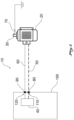
- Fig. 1 shows an embodiment of a drive system 10 according to the invention consisting of an electrical motor 20 with a drive shaft 30, which is controlled by a converter 40 via a power supply line 50 and a signal line 60.
- the drive shaft 30 is grounded via a shaft grounding element 70.
- the power supply line 50 and the signal line 60 comprise filter units 80 and 90, respectively, which are provided in openings 110,120 of a cabinet 100 accommodating the converter 40.
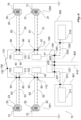
- Fig. 2 shows another embodiment of a drive system 10 according to the invention with multiple components.
- the embodiment shown in Fig. 2 comprises four electrical motors 20-23 with respective drive shafts 30-33.
- Each electrical motor 20-23 is connected with a converter 40-43 via a power supply line 50-53 and a signal line 60-63 and each drive shaft 30-33 is grounded via a shaft grounding element 70-73.
- the four converters 40-43 are accommodated in an electromagnetically shielded cabinet 100 and the power supply lines 50-53 and signal lines 60-63 leading to the respective electrical motors 20-23 are guided through openings 110-113/120-123 in the shielded cabinet 100 via corresponding filter units 80-83/90-93, respectively.
- the shielded cabinet 100 further comprises an opening 131 and a door 130.
- An electrically conductive element 132 is provided so as to enable electrical contact between the cabinet 100 and the door 130.
- the shielded cabinet 100 further comprises a control unit 140, which is configured to control the converters 40-43 as well as two external units 310,311, like switches, sensors, and/or encoders, that are located outside the cabinet 100 and accommodated in separate electromagnetically shielded housings 300,301.
- the electric motors 20-23 are also accommodated in electromagnetically shielded housings 200,201.
- the control unit 140 is connected with the external units 310,311 via respective power supply lines 320,321 and optical signal lines 330,331 and is supplied itself by corresponding power and signal lines 410 and 420, respectively, from the outside of the shielded cabinet.
- the openings for the power supply lines 320,321 in the shielded cabinet 100 and in the shielded housings 300,301, as well as the openings in the shielded cabinet 110 for the power and signal lines 410 and 420, respectively, supplying the control unit 140, are equipped with corresponding filters 340,341,430,440.
- electro-magnetic shieldings 100,200,201,300,301, line filters 80-83,90-93,340,341,430,440 and optical signal lines 330,331 in combination with shaft grounding elements 70-73 allows to reduce the EMI emissions to a minimum.
Landscapes
- Engineering & Computer Science (AREA)
- Power Engineering (AREA)
- Physics & Mathematics (AREA)
- Electromagnetism (AREA)
- Control Of Electric Motors In General (AREA)
- Shielding Devices Or Components To Electric Or Magnetic Fields (AREA)
- Control Of Multiple Motors (AREA)
Description
- Radio astronomical devices are exceptionally sensitive in order to detect weak signals from remote extraterrestrial objects. Therefore, they are also exceptionally prone to noise from electromagnetic interferences (EMI) emitted by electrical equipment, in particular by electrical drive systems with servo converters.
- Known solutions for reducing or shielding EMI emissions from electrical equipment are not able to reduce the EMI emissions to the level required in radio astronomy by using signal filtering in signal processing (see
US 10 483 902 B1 - Hence, the objective of the present invention is to provide a drive system meeting the requirements of radio astronomical devices in terms of EMI emissions in order to improve the integrity of signals detected by radio astronomical devices.
- This objective is achieved by a new combination of means to reduce EMI emissions of electrical components of the drive system according to claim 1, as well as by the preferred embodiments thereof defined in the dependent claims.
- The drive system according to the invention comprises a first motor, a first converter configured to supply a first drive power to the first motor and to control a rotational speed and/or a rotational position of the first motor, a first power supply line for providing the first motor with the first drive power, and a first signal line for providing the first converter with a signal indicating a measured rotational speed and/or a measured rotational position of the first motor, wherein the drive system comprises a shaft grounding element for grounding a drive shaft of the first motor and wherein at least one of the first power supply line and the first signal line further comprises a line filter unit being a low-pass filter for filtering electromagnetic interference signals.
- Electric motors operated by servo converters cause electrical discharges between the rotating shaft and the fixed housing due to the control signals and the internal structure of the motor, resulting in high-energy, high-frequency disturbances or even spark discharges. Such disturbances can spread to the converter, even via shielded electrical lines. Grounding of the motor shaft turned out to be an effective means to reduce EMI emissions from sparking and the associated radiation of drive systems in radio astronomy and is applied for the first time to reduce EMI emissions by the present invention.
- As the power electronics and the motors of a drive system are usually spaced apart from each other and connected by electrical power supply lines, highly interfering signals are emitted (e.g. 3-phase 400V continuously pulse-width modulated (PWM) power supply lines of the drive motors). The EMI emissions of such electrical power supply lines can be reduced by using filters particularly developed for the corresponding application.
- Different filters are required for the low-frequency, pulse-modulated and for the high-frequency signal components created by the converter electronics. High-frequency interferences, which are only generated in the motor due to the low-frequency PWM signals, can be fed back directly to the power module of the servo converter. High-frequency signals, which are generated in the converter or in the safety electronics, require a low-pass filter with a low blocking frequency and a high blocking attenuation to prevent propagation. Both filters can be used cascaded.
- Experiments revealed that a combination of shaft grounding and low-pass filters contributes synergistically to reducing EMI emissions, especially when the filter blocks frequencies above 30 MHz or preferably above 8 MHz. As a result, the signals detected by the radio astronomical device are less prone to noise, thereby improving the quality and integrity of the detected signals.
- The shaft grounding element comprises preferably a sliding contact element configured to enable electrical contact between the drive shaft of the first motor and the shaft grounding element while the drive shaft of the first motor is being moved in relation to the sliding contact element.
- Using a sliding contact element is an effective and efficient means to connect the drive shaft with the shaft grounding element while not obstructing the relative movement of the drive shaft. The sliding contact element can further be equipped with a roller or the like to establish electrical contact with the drive shaft while reducing the friction between the sliding contact element in the drive shaft during the relative movement.
- The shaft grounding element for grounding the drive shaft of the first motor can also be provided in the first motor, preferably by establishing electrical conductivity between the drive shaft and the grounded casing of the first motor.
- As casings of electric motors are usually grounded already, grounding the drive shaft via the motor casing is easy to implement and therefore rather cost efficient.
- It is further preferred that at least the first power supply line comprises an all-pole sine filter for smoothening the PWM signal from the first converter, in particular by blocking frequencies below 4 MHz, preferably below 10 MHz.
- A combination of such filters with the means introduced in claim 1 has proven to contribute synergistically to reducing EMI emissions while being relatively easy to implement.
- The line filter unit and/or the first converter can further comprise a feedback module configured to add, to a signal of the first drive power, high-frequency feedback signals for reducing and/or cancelling high-frequency interference signals generated by the first motor.
- By adding essentially inverted high-frequency signals to the high-frequency signals transmitted in the first power supply line, both high-frequency signals essentially cancel each other out, resulting in a smoother signal, which in turn causes less EMI emissions.
- It is preferred that the first converter is accommodated in a first cabinet being electrically conductive and having at least one cabinet door provided in an opening of the first cabinet, wherein an electrically conductive element is provided to enable electrical contact between the cabinet door and the rest of the first cabinet when the cabinet door is in a closed state.
- EMI emitting components are preferably installed in a closed cabinet with high shielding attenuation in order to maintain a self-contained, shielded, spatially limited space known as a Faraday cage. Structural measures like reinforcement frames on openings holding filtering components are important measures for achieving good surface properties, high contact pressures, low-resistance electrical connections, and as a result, effective EMI shielding.
- Conductive sealing material on the door and attached flanged components increase reliability and reproducibility. Highly interfering systems such as safety electronics, motion control computers or power and control electronics of the motors should therefore be installed in such cabinet.
- The electrically conductive element is preferably provided to enable continuous electrical contact between the cabinet door and the rest of the first cabinet while the electrically conductive element preferably comprises a copper-beryllium alloy.
- By enabling continuous electrical contact between the cabinet door and the rest of the first cabinet, a reasonable shielding effect can be achieved even when the cabinet door is not entirely closed. Copper-beryllium alloys feature a good electrical conductivity and various hardness levels and are, therefore, well suited for forming the electrically conductive contact element.
- It is further preferred that at least the first signal line and/or at least the first power supply line is guided from an interior portion of the first cabinet to an outside portion of the first cabinet via at least one opening, in which the line filter unit for filtering electromagnetic interference signals is provided.
- Electrical connections between devices, assemblies or system components can be established via filters to maintain the shielding effect of the cabinet as well as of individual assemblies and to avoid interferences spreading via electrical connections (wired EMI). The filtering components have a high blocking attenuation and a wide bandwidth and should not distort the intended signal. In case of interference sources with a high level of conducted interference, filter components can be connected in series.
- The line filter unit is preferably configured to filter frequencies in a range between 8 MHz and 18000 MHz with a blocking attenuation of at least 60 dB, preferably at least 100 dB. Experiments have revealed that corresponding filters can reduce EMI emissions very effectively.
- Furthermore, a plurality of line filter units can be sequentially arranged at least in the first signal line and/or the first power supply line. The sequential arrangement of line filter units helps to further reduce high-frequency signals, thereby further reducing EMI emissions.
- In another embodiment, the drive system further comprises at least an electro-magnetically shielded housing accommodating at least a limit switch for detecting an end position of an entity to be aligned, such as an antenna, a reflector, a telescope or the like, and/or at least a sensor such as a temperature and/or humidity sensor, and/or at least a position encoder for measuring a position of the motor and/or a position of the entity to be aligned.
- Components for controlling and operating the drive system that cannot be accommodated within the shielded cabinet (like position encoders or limit switches) can be accommodated in separate housings with high EMI shielding attenuation. Electrical connections to these units can also be shielded and/or made EMI-compliant (e.g. via filters).
- Preferably, at least one signal line and/or at least one power supply line of a housing is guided from an interior portion of the housing to an outside portion of the housing via at least one opening comprising a line filter unit for filtering electromagnetic interference signals is provided.
- Guiding electrical signal and/or power supply lines through the walls of the shielded housing via filter units further reduces the EMI emissions outside the shielded housing.
- It is further preferred that at least the first power supply line and/or at least the first signal line is electromagnetically shielded. Shielding electric power and/or signal lines that run through non-shielded environments further reduces the EMI emissions outside the shielded environments.
- It is further preferred that at least an optical signal line, such as an optical fiber line, is provided so as to enable optical signal transmission, preferably between at least one component accommodated in the housing and at least one component accommodated in the first cabinet. The optical signal line is preferably guided through the cabinet and/or housing via wave guides.
- EMI emission is inherent in electrical communication. Therefore, all external communication (with I/O units, drive control or command transmission) should be based on optical fiber communication, which does not emit any EMI radiation. For the same reason, line filters or electro-magnetic shieldings are not provided for optical signal lines.
- In a particular embodiment, the drive system is part of a telescope that further comprises a support structure and a reflector and is configured such that the reflector is rotatable around a substantially vertical axis and/or around a substantially horizontal axis by means of the drive system.
- As telescopes are exceptionally sensitive and prone to noise caused by EMI emissions from electrical equipment, the EMI-optimized electrical drive system disclosed herein is particularly suitable to be used in telescopes since the reduction of interfering signals significantly improves the quality of the detected signals.
-
- Fig. 1
- is a schematic view of a drive system according to a basic embodiment of the invention
- Fig. 2
- is a schematic view of a drive system according to a more complex embodiment of the invention
-
Fig. 1 shows an embodiment of adrive system 10 according to the invention consisting of anelectrical motor 20 with adrive shaft 30, which is controlled by aconverter 40 via apower supply line 50 and asignal line 60. Thedrive shaft 30 is grounded via ashaft grounding element 70. Thepower supply line 50 and thesignal line 60 comprisefilter units cabinet 100 accommodating theconverter 40. -
Fig. 2 shows another embodiment of adrive system 10 according to the invention with multiple components. The embodiment shown inFig. 2 comprises four electrical motors 20-23 with respective drive shafts 30-33. Each electrical motor 20-23 is connected with a converter 40-43 via a power supply line 50-53 and a signal line 60-63 and each drive shaft 30-33 is grounded via a shaft grounding element 70-73. - The four converters 40-43 are accommodated in an electromagnetically shielded
cabinet 100 and the power supply lines 50-53 and signal lines 60-63 leading to the respective electrical motors 20-23 are guided through openings 110-113/120-123 in the shieldedcabinet 100 via corresponding filter units 80-83/90-93, respectively. The shieldedcabinet 100 further comprises anopening 131 and adoor 130. An electricallyconductive element 132 is provided so as to enable electrical contact between thecabinet 100 and thedoor 130. - In this embodiment, the shielded
cabinet 100 further comprises acontrol unit 140, which is configured to control the converters 40-43 as well as two external units 310,311, like switches, sensors, and/or encoders, that are located outside thecabinet 100 and accommodated in separate electromagnetically shielded housings 300,301. Preferably, the electric motors 20-23 are also accommodated in electromagnetically shielded housings 200,201. - The
control unit 140 is connected with the external units 310,311 via respective power supply lines 320,321 and optical signal lines 330,331 and is supplied itself by corresponding power andsignal lines cabinet 100 and in the shielded housings 300,301, as well as the openings in the shieldedcabinet 110 for the power andsignal lines control unit 140, are equipped with corresponding filters 340,341,430,440. - The use of electro-magnetic shieldings 100,200,201,300,301, line filters 80-83,90-93,340,341,430,440 and optical signal lines 330,331 in combination with shaft grounding elements 70-73, allows to reduce the EMI emissions to a minimum.
-
- 10
- drive system
- 20-23
- electric motor
- 30-33
- drive shaft
- 40-43
- converter
- 50-53
- power line (for motor)
- 60-63
- signal line (for motor)
- 70-73
- shaft grounding element
- 80-83
- filter unit (for motor power line)
- 90-93
- filter unit (for motor signal line)
- 100
- cabinet
- 110-113
- cabinet opening (for motor power line)
- 120-123
- cabinet opening (for motor signal line)
- 130
- cabinet door
- 131
- cabinet door opening
- 132
- electrically conductive element
- 140
- control unit
- 200,201
- housing (for motor)
- 300,301
- housing (for external unit)
- 310,311
- external unit
- 320,321
- power line (for external unit)
- 330,331
- filter unit (for external unit power line)
- 340,341
- optical signal line (for external unit)
- 410
- power line (for control unit)
- 420
- signal line (for control unit)
- 430
- filter unit (for control unit power line)
- 440
- filter unit (for control unit signal line)
Claims (15)
- A drive system (10) for sensitive devices used in radio astronomy, the drive system (10) comprising:a first motor (20);a first converter (40) configured to supply a first drive power to the first motor (20), and to control a rotational speed and/or a rotational position of the first motor (20);a first power supply line (50) for providing the first motor (20) with the first drive power; anda first signal line (60) for providing the first converter (40) with a signal indicating a measured rotational speed and/or a measured rotational position of the first motor (20),the drive system is characterised in thatthe drive system (10) further comprises a shaft grounding element (70) for grounding a drive shaft (30) of the first motor (20), andwherein each one of the first power supply line (50) and the first signal line (60) further comprises a line filter unit (80, 90) being a low-pass filter for filtering electromagnetic interference signals by blocking frequencies higher than 30 MHz, preferably higher than 8 MHz.
- The drive system (10) of claim 1, wherein the shaft grounding element (70) comprises a sliding contact element configured to enable electrical contact between the drive shaft (30) of the first motor (20) and the shaft grounding element (70) while the drive shaft (30) of the first motor (20) is moved relative to the sliding contact element.
- The drive system (10) of any one of the preceding claims, wherein the shaft grounding element (70) for grounding the drive shaft (30) of the first motor (20) is provided in the first motor (20), preferably by establishing electrical conductivity between the drive shaft (30) and the grounded casing of the first motor (20).
- The drive system (10) of any one of the preceding claims, wherein at least the first power supply line (50) further comprises an all-pole sine filter for smoothening the PWM signal from the first converter (40) by blocking frequencies lower than 4 MHz, preferably lower than 10 MHz.
- The drive system (10) of any one of the preceding claims, wherein the line filter unit (80) and/or the first converter (40) further comprises a feedback module configured to add, to a signal of the first drive power, high-frequency feedback signals for reducing and/or cancelling high-frequency interference signals generated by the first motor (20).
- The drive system (10) of any one of the preceding claims, wherein the first converter (40) is accommodated in a first cabinet (100) being electrically conductive and having at least one cabinet door (130) provided in an opening (131) of the first cabinet (100), wherein an electrically conductive element (132) is provided so as to enable electrical contact between the cabinet door (130) and the rest of the first cabinet (100) when the cabinet door (130) is in a closed state.
- The drive system (10) of claim 6, wherein the electrically conductive element (132) is provided so as to enable continuous electrical contact between the cabinet door (130) and the rest of the first cabinet (100) and the electrically conductive element (132) preferably comprises a copper-beryllium alloy.
- The drive system (10) of claim 6 or 7, wherein at least one of the first power supply line (50) and the first signal line (60) is guided from an interior portion of the first cabinet (100) to an outside portion of the first cabinet (100) via at least one opening (110, 120), wherein the line filter unit (80, 90) is provided in the at least one opening (110, 120).
- The drive system (10) of any one of the preceding claims, wherein the line filter unit (80, 90) is configured to filter frequencies in a range between 8 MHz and 18000 MHz, wherein a blocking attenuation of the line filter unit is at least 60 dB, preferably at least 100 dB.
- The drive system (10) of any one of the preceding claims, wherein a plurality of line filter units (80, 90) are sequentially arranged at least in one of the first power supply line (50) and the first signal line (60) and/or at least in one of a power supply line (410) and a signal line (420) of the control unit (140).
- The drive system (10) of any one of the preceding claims, further comprising at least an electromagnetically shielded housing (300, 301) accommodating at least one of: a limit switch for detecting an end position of an entity to be aligned, such as an antenna, a reflector, a telescope or the like; a sensor such as a temperature and/or humidity sensor; a position encoder for measuring a position of the motor and/or a position of the entity to be aligned.
- The drive system of claim 11, wherein at least one of a power supply line (320, 321) and a signal line (340, 341) of a housing (200, 201, 300, 301) is guided from an interior portion of the housing (200, 201, 300, 301) to an outside portion of the housing (200, 201, 300, 301) via at least one opening, wherein a line filter unit (330, 331) is provided in the at least one opening.
- The drive system (10) of any one of the preceding claims, wherein at least one of the first power supply line (50) and the first signal line (60) and/or at least one of a power supply line (320, 321) and a signal line (340, 341) of a housing (200, 201, 300, 301) and/or at least one of a power supply line (410) and a signal line (420) of the control unit (140) or the cabinet (100) is electro-magnetically shielded.
- The drive system (10) of any one of the preceding claims, wherein at least one of the first signal line (60) and a signal line (340, 341) of a housing (200, 201, 300, 301) is an optical signal line, which is guided through the cabinet (100) and/or housing (200, 201, 300, 301) via waveguides.
- A telescope comprising a support structure, a reflector, and the drive system (10) of any one of the preceding claims, the telescope being configured such that the reflector is rotatable around a substantially vertical axis and/or around a substantially horizontal axis by means of the drive system (10) .
Applications Claiming Priority (1)
| Application Number | Priority Date | Filing Date | Title |
|---|---|---|---|
| PCT/EP2020/071101 WO2022022799A1 (en) | 2020-07-27 | 2020-07-27 | Avoiding electromagnetic interference (emi) in electrical equipment and drive systems, e.g. used in radio astronomy |
Publications (3)
| Publication Number | Publication Date |
|---|---|
| EP4189829A1 EP4189829A1 (en) | 2023-06-07 |
| EP4189829C0 EP4189829C0 (en) | 2024-08-21 |
| EP4189829B1 true EP4189829B1 (en) | 2024-08-21 |
Family
ID=71786976
Family Applications (1)
| Application Number | Title | Priority Date | Filing Date |
|---|---|---|---|
| EP20746208.6A Active EP4189829B1 (en) | 2020-07-27 | 2020-07-27 | Avoiding electromagnetic interference (emi) in electrical equipment and drive systems, used in radio astronomy |
Country Status (6)
| Country | Link |
|---|---|
| US (1) | US12451835B2 (en) |
| EP (1) | EP4189829B1 (en) |
| CN (1) | CN116458055A (en) |
| ES (1) | ES2987746T3 (en) |
| WO (1) | WO2022022799A1 (en) |
| ZA (1) | ZA202301367B (en) |
Citations (3)
| Publication number | Priority date | Publication date | Assignee | Title |
|---|---|---|---|---|
| WO2012068655A1 (en) | 2010-11-22 | 2012-05-31 | Bilk Edinez | Silo for separating crushed sand from powdery material |
| EP2576271A1 (en) | 2010-05-27 | 2013-04-10 | Nissan Motor Co., Ltd | Power transmission device for electric vehicle |
| US10483902B1 (en) | 2018-08-29 | 2019-11-19 | Rockwell Automation Technologies, Inc. | System and method for reducing current harmonic distortion in a motor controller |
Family Cites Families (12)
| Publication number | Priority date | Publication date | Assignee | Title |
|---|---|---|---|---|
| US7511443B2 (en) * | 2002-09-26 | 2009-03-31 | Barrett Technology, Inc. | Ultra-compact, high-performance motor controller and method of using same |
| US20080187147A1 (en) * | 2007-02-05 | 2008-08-07 | Berner Miranda S | Noise reduction systems and methods |
| WO2011021485A1 (en) * | 2009-08-19 | 2011-02-24 | 株式会社安川電機 | Output filter and electric motor drive system provided therewith |
| US20140091622A1 (en) * | 2011-04-15 | 2014-04-03 | Deka Products Limited Partnership | Modular Power Conversion System |
| DE102012108869A1 (en) * | 2012-09-20 | 2014-03-20 | Ebm-Papst Mulfingen Gmbh & Co. Kg | "Thermodynamic cycle process plant" |
| US9560729B2 (en) * | 2013-09-09 | 2017-01-31 | Cutsforth, Inc. | Grounding rope for a shaft grounding apparatus of a dynamo-electric machine |
| EP3273585B1 (en) * | 2015-03-16 | 2023-04-26 | Mitsubishi Electric Corporation | Power circuit device |
| US10177702B2 (en) * | 2015-08-12 | 2019-01-08 | Samsung Electronics Co., Ltd. | Conduction noise filtering circuit, inverting device, and compressor |
| US9800133B2 (en) * | 2016-03-22 | 2017-10-24 | Infineon Technologies Ag | Active common mode cancellation |
| US10250177B2 (en) * | 2017-05-23 | 2019-04-02 | Regal Beloit America, Inc. | Floating ground assembly for electric motor control assembly |
| CN111095690A (en) * | 2017-09-11 | 2020-05-01 | 伊利诺斯工具制品有限公司 | Method and apparatus for alleviating voltage on a rotating shaft |
| US10476381B1 (en) * | 2018-11-13 | 2019-11-12 | Rockwell Automation Technologies, Inc. | Power conversion system and filter therefor |
-
2020
- 2020-07-27 CN CN202080104521.5A patent/CN116458055A/en active Pending
- 2020-07-27 EP EP20746208.6A patent/EP4189829B1/en active Active
- 2020-07-27 US US18/018,499 patent/US12451835B2/en active Active
- 2020-07-27 ES ES20746208T patent/ES2987746T3/en active Active
- 2020-07-27 WO PCT/EP2020/071101 patent/WO2022022799A1/en not_active Ceased
-
2023
- 2023-02-02 ZA ZA2023/01367A patent/ZA202301367B/en unknown
Patent Citations (3)
| Publication number | Priority date | Publication date | Assignee | Title |
|---|---|---|---|---|
| EP2576271A1 (en) | 2010-05-27 | 2013-04-10 | Nissan Motor Co., Ltd | Power transmission device for electric vehicle |
| WO2012068655A1 (en) | 2010-11-22 | 2012-05-31 | Bilk Edinez | Silo for separating crushed sand from powdery material |
| US10483902B1 (en) | 2018-08-29 | 2019-11-19 | Rockwell Automation Technologies, Inc. | System and method for reducing current harmonic distortion in a motor controller |
Non-Patent Citations (5)
| Title |
|---|
| BERGANO MIGUEL, BARBOSA DOMINGOS, RIBEIRO VALéRIO: "EMI apparatus performance of a fully steerable radio telescope", 28 May 2018 (2018-05-28), pages 1 - 2, XP055794812, Retrieved from the Internet <URL:https://www.ursi.org/proceedings/procAT18/papers/E0206.pdf> [retrieved on 20210413] |
| JESSNER A., ROB MILLENAAR, HANS VAN DER MAREL, SCHLAGENHAUFER F., H.C. READER, R.T. LORD: "EMI Protection and Threshold Levels for the SKA", RESEARCHGATE, 1 July 2014 (2014-07-01), XP093279933, Retrieved from the Internet <URL:https://www.researchgate.net/publication/272012855_EMI_Protection_and_Threshold_Levels_for_the_SKA> DOI: 10.13140/2.1.4824.6562 |
| JONAS JUSTIN: "The MeerKAT Radio Telescope", PROCEEDINGS OF MEERKAT SCIENCE: ON THE PATHWAY TO THE SKA — POS(MEERKAT2016), SISSA MEDIALAB, 25 May 2016 (2016-05-25) - 27 May 2016 (2016-05-27), pages 001, XP093279929, DOI: 10.22323/1.277.0001 |
| WANG XU; LI JUN; WANG YIQING; CHO KWANG JAE; KIM GLORIA; GJYREZI ADA; KOENIG LYDIA; GIANNAKAKOU PARASKEVI; SHIN HYUNG JU C; TIGHIO: "HFT-T, a targeting nanoparticle, enhances specific delivery of paclitaxel to folate receptor-positive tumors.", ACS NANO, AMERICAN CHEMICAL SOCIETY, US, vol. 3, no. 10, 27 October 2009 (2009-10-27), US , pages 3165 - 3174, XP008121949, ISSN: 1936-086X, DOI: 10.1021/nn900649v |
| WIKIPEDIA: "Ferrite Bead", WIKIPEDIA, 24 May 2016 (2016-05-24), pages 1 - 3, XP055915404 |
Also Published As
| Publication number | Publication date |
|---|---|
| CN116458055A (en) | 2023-07-18 |
| ZA202301367B (en) | 2024-09-25 |
| US20230318515A1 (en) | 2023-10-05 |
| EP4189829C0 (en) | 2024-08-21 |
| WO2022022799A1 (en) | 2022-02-03 |
| US12451835B2 (en) | 2025-10-21 |
| EP4189829A1 (en) | 2023-06-07 |
| ES2987746T3 (en) | 2024-11-18 |
Similar Documents
| Publication | Publication Date | Title |
|---|---|---|
| EP0729294B1 (en) | Arrangement for preventing eletromagnetic interference | |
| EP0843512A3 (en) | High frequency emi shield with air flow for electronic device enclosure | |
| US6566973B2 (en) | EMI enclosure having a waveguide for cables | |
| MY124778A (en) | Conforming shielded form for electronic component assemblies | |
| EP2463966B1 (en) | Integrated connector shield ring for shielded enclosures | |
| US20050247471A1 (en) | Electromagnetic shield using meta-material | |
| EP3235357B1 (en) | Feed-through | |
| US12451835B2 (en) | Avoiding electromagnetic interference (EMI) in electrical equipment and drive systems, e.g. used in radio astronomy | |
| CN112584042B (en) | Video camera | |
| KR101841638B1 (en) | Electromagnetic-Pulse Shield Rack | |
| US20200170589A1 (en) | Patient positioning apparatus | |
| EP1150555A2 (en) | Housing for a frequency converter | |
| JP2547937B2 (en) | Data processing system and housing with low electromagnetic radiation | |
| JPH08148877A (en) | Electronic device shielding device | |
| JP2007088332A (en) | EMC shield case | |
| KR102539155B1 (en) | Hood for preventing the interference of frequency of projectile antenna | |
| JPH0456196A (en) | Cable introduction port electromagnetic shield device | |
| SE1950559A1 (en) | Feed-through | |
| KR101412028B1 (en) | Insert blocks of the MCT Packing system | |
| SE1950558A1 (en) | Feed-through | |
| CN110446410A (en) | A kind of multilayer screen ventilation waveguide window construction | |
| JP2025075249A (en) | electronic equipment | |
| KR200257771Y1 (en) | Apparatus for cable shielding panel in communication device | |
| KR102485052B1 (en) | Information and communication box | |
| Matisoff | Radio frequency and electromagnetic shielding |
Legal Events
| Date | Code | Title | Description |
|---|---|---|---|
| STAA | Information on the status of an ep patent application or granted ep patent |
Free format text: STATUS: UNKNOWN |
|
| STAA | Information on the status of an ep patent application or granted ep patent |
Free format text: STATUS: THE INTERNATIONAL PUBLICATION HAS BEEN MADE |
|
| PUAI | Public reference made under article 153(3) epc to a published international application that has entered the european phase |
Free format text: ORIGINAL CODE: 0009012 |
|
| STAA | Information on the status of an ep patent application or granted ep patent |
Free format text: STATUS: REQUEST FOR EXAMINATION WAS MADE |
|
| 17P | Request for examination filed |
Effective date: 20230222 |
|
| AK | Designated contracting states |
Kind code of ref document: A1 Designated state(s): AL AT BE BG CH CY CZ DE DK EE ES FI FR GB GR HR HU IE IS IT LI LT LU LV MC MK MT NL NO PL PT RO RS SE SI SK SM TR |
|
| DAV | Request for validation of the european patent (deleted) | ||
| DAX | Request for extension of the european patent (deleted) | ||
| GRAP | Despatch of communication of intention to grant a patent |
Free format text: ORIGINAL CODE: EPIDOSNIGR1 |
|
| STAA | Information on the status of an ep patent application or granted ep patent |
Free format text: STATUS: GRANT OF PATENT IS INTENDED |
|
| INTG | Intention to grant announced |
Effective date: 20240319 |
|
| GRAS | Grant fee paid |
Free format text: ORIGINAL CODE: EPIDOSNIGR3 |
|
| GRAA | (expected) grant |
Free format text: ORIGINAL CODE: 0009210 |
|
| STAA | Information on the status of an ep patent application or granted ep patent |
Free format text: STATUS: THE PATENT HAS BEEN GRANTED |
|
| AK | Designated contracting states |
Kind code of ref document: B1 Designated state(s): AL AT BE BG CH CY CZ DE DK EE ES FI FR GB GR HR HU IE IS IT LI LT LU LV MC MK MT NL NO PL PT RO RS SE SI SK SM TR |
|
| REG | Reference to a national code |
Ref country code: GB Ref legal event code: FG4D |
|
| REG | Reference to a national code |
Ref country code: CH Ref legal event code: EP |
|
| REG | Reference to a national code |
Ref country code: IE Ref legal event code: FG4D |
|
| REG | Reference to a national code |
Ref country code: DE Ref legal event code: R096 Ref document number: 602020036227 Country of ref document: DE |
|
| U01 | Request for unitary effect filed |
Effective date: 20240904 |
|
| U07 | Unitary effect registered |
Designated state(s): AT BE BG DE DK EE FI FR IT LT LU LV MT NL PT RO SE SI Effective date: 20240923 |
|
| REG | Reference to a national code |
Ref country code: ES Ref legal event code: FG2A Ref document number: 2987746 Country of ref document: ES Kind code of ref document: T3 Effective date: 20241118 |
|
| PG25 | Lapsed in a contracting state [announced via postgrant information from national office to epo] |
Ref country code: NO Free format text: LAPSE BECAUSE OF FAILURE TO SUBMIT A TRANSLATION OF THE DESCRIPTION OR TO PAY THE FEE WITHIN THE PRESCRIBED TIME-LIMIT Effective date: 20241121 |
|
| PG25 | Lapsed in a contracting state [announced via postgrant information from national office to epo] |
Ref country code: GR Free format text: LAPSE BECAUSE OF FAILURE TO SUBMIT A TRANSLATION OF THE DESCRIPTION OR TO PAY THE FEE WITHIN THE PRESCRIBED TIME-LIMIT Effective date: 20241122 Ref country code: PL Free format text: LAPSE BECAUSE OF FAILURE TO SUBMIT A TRANSLATION OF THE DESCRIPTION OR TO PAY THE FEE WITHIN THE PRESCRIBED TIME-LIMIT Effective date: 20240821 |
|
| PG25 | Lapsed in a contracting state [announced via postgrant information from national office to epo] |
Ref country code: IS Free format text: LAPSE BECAUSE OF FAILURE TO SUBMIT A TRANSLATION OF THE DESCRIPTION OR TO PAY THE FEE WITHIN THE PRESCRIBED TIME-LIMIT Effective date: 20241221 |
|
| PG25 | Lapsed in a contracting state [announced via postgrant information from national office to epo] |
Ref country code: HR Free format text: LAPSE BECAUSE OF FAILURE TO SUBMIT A TRANSLATION OF THE DESCRIPTION OR TO PAY THE FEE WITHIN THE PRESCRIBED TIME-LIMIT Effective date: 20240821 |
|
| PG25 | Lapsed in a contracting state [announced via postgrant information from national office to epo] |
Ref country code: RS Free format text: LAPSE BECAUSE OF FAILURE TO SUBMIT A TRANSLATION OF THE DESCRIPTION OR TO PAY THE FEE WITHIN THE PRESCRIBED TIME-LIMIT Effective date: 20241121 |
|
| PG25 | Lapsed in a contracting state [announced via postgrant information from national office to epo] |
Ref country code: RS Free format text: LAPSE BECAUSE OF FAILURE TO SUBMIT A TRANSLATION OF THE DESCRIPTION OR TO PAY THE FEE WITHIN THE PRESCRIBED TIME-LIMIT Effective date: 20241121 Ref country code: PL Free format text: LAPSE BECAUSE OF FAILURE TO SUBMIT A TRANSLATION OF THE DESCRIPTION OR TO PAY THE FEE WITHIN THE PRESCRIBED TIME-LIMIT Effective date: 20240821 Ref country code: NO Free format text: LAPSE BECAUSE OF FAILURE TO SUBMIT A TRANSLATION OF THE DESCRIPTION OR TO PAY THE FEE WITHIN THE PRESCRIBED TIME-LIMIT Effective date: 20241121 Ref country code: IS Free format text: LAPSE BECAUSE OF FAILURE TO SUBMIT A TRANSLATION OF THE DESCRIPTION OR TO PAY THE FEE WITHIN THE PRESCRIBED TIME-LIMIT Effective date: 20241221 Ref country code: HR Free format text: LAPSE BECAUSE OF FAILURE TO SUBMIT A TRANSLATION OF THE DESCRIPTION OR TO PAY THE FEE WITHIN THE PRESCRIBED TIME-LIMIT Effective date: 20240821 Ref country code: GR Free format text: LAPSE BECAUSE OF FAILURE TO SUBMIT A TRANSLATION OF THE DESCRIPTION OR TO PAY THE FEE WITHIN THE PRESCRIBED TIME-LIMIT Effective date: 20241122 |
|
| PG25 | Lapsed in a contracting state [announced via postgrant information from national office to epo] |
Ref country code: SM Free format text: LAPSE BECAUSE OF FAILURE TO SUBMIT A TRANSLATION OF THE DESCRIPTION OR TO PAY THE FEE WITHIN THE PRESCRIBED TIME-LIMIT Effective date: 20240821 |
|
| PG25 | Lapsed in a contracting state [announced via postgrant information from national office to epo] |
Ref country code: CZ Free format text: LAPSE BECAUSE OF FAILURE TO SUBMIT A TRANSLATION OF THE DESCRIPTION OR TO PAY THE FEE WITHIN THE PRESCRIBED TIME-LIMIT Effective date: 20240821 |
|
| PG25 | Lapsed in a contracting state [announced via postgrant information from national office to epo] |
Ref country code: SK Free format text: LAPSE BECAUSE OF FAILURE TO SUBMIT A TRANSLATION OF THE DESCRIPTION OR TO PAY THE FEE WITHIN THE PRESCRIBED TIME-LIMIT Effective date: 20240821 |
|
| PLBI | Opposition filed |
Free format text: ORIGINAL CODE: 0009260 |
|
| PLAB | Opposition data, opponent's data or that of the opponent's representative modified |
Free format text: ORIGINAL CODE: 0009299OPPO |
|
| PLAX | Notice of opposition and request to file observation + time limit sent |
Free format text: ORIGINAL CODE: EPIDOSNOBS2 |
|
| 26 | Opposition filed |
Opponent name: MTEX ANTENNA TECHNOLOGY GMBH Effective date: 20250513 |
|
| R26 | Opposition filed (corrected) |
Opponent name: MTEX ANTENNA TECHNOLOGY GMBH Effective date: 20250513 |
|
| U20 | Renewal fee for the european patent with unitary effect paid |
Year of fee payment: 6 Effective date: 20250728 |
|
| PLBB | Reply of patent proprietor to notice(s) of opposition received |
Free format text: ORIGINAL CODE: EPIDOSNOBS3 |
|
| PGFP | Annual fee paid to national office [announced via postgrant information from national office to epo] |
Ref country code: ES Payment date: 20250801 Year of fee payment: 6 |
|
| PGFP | Annual fee paid to national office [announced via postgrant information from national office to epo] |
Ref country code: GB Payment date: 20250703 Year of fee payment: 6 |
|
| REG | Reference to a national code |
Ref country code: CH Ref legal event code: H13 Free format text: ST27 STATUS EVENT CODE: U-0-0-H10-H13 (AS PROVIDED BY THE NATIONAL OFFICE) Effective date: 20260224 |
|
| PG25 | Lapsed in a contracting state [announced via postgrant information from national office to epo] |
Ref country code: CH Free format text: LAPSE BECAUSE OF NON-PAYMENT OF DUE FEES Effective date: 20250731 |