EP4189768B1 - Battery cell thermal runaway barrier - Google Patents
Battery cell thermal runaway barrier Download PDFInfo
- Publication number
- EP4189768B1 EP4189768B1 EP21752219.2A EP21752219A EP4189768B1 EP 4189768 B1 EP4189768 B1 EP 4189768B1 EP 21752219 A EP21752219 A EP 21752219A EP 4189768 B1 EP4189768 B1 EP 4189768B1
- Authority
- EP
- European Patent Office
- Prior art keywords
- thermal runaway
- layer
- nonwoven fibrous
- thermal insulation
- thermal
- Prior art date
- Legal status (The legal status is an assumption and is not a legal conclusion. Google has not performed a legal analysis and makes no representation as to the accuracy of the status listed.)
- Active
Links
Images


Classifications
-
- D—TEXTILES; PAPER
- D04—BRAIDING; LACE-MAKING; KNITTING; TRIMMINGS; NON-WOVEN FABRICS
- D04H—MAKING TEXTILE FABRICS, e.g. FROM FIBRES OR FILAMENTARY MATERIAL; FABRICS MADE BY SUCH PROCESSES OR APPARATUS, e.g. FELTS, NON-WOVEN FABRICS; COTTON-WOOL; WADDING ; NON-WOVEN FABRICS FROM STAPLE FIBRES, FILAMENTS OR YARNS, BONDED WITH AT LEAST ONE WEB-LIKE MATERIAL DURING THEIR CONSOLIDATION
- D04H1/00—Non-woven fabrics formed wholly or mainly of staple fibres or like relatively short fibres
- D04H1/40—Non-woven fabrics formed wholly or mainly of staple fibres or like relatively short fibres from fleeces or layers composed of fibres without existing or potential cohesive properties
- D04H1/58—Non-woven fabrics formed wholly or mainly of staple fibres or like relatively short fibres from fleeces or layers composed of fibres without existing or potential cohesive properties by applying, incorporating or activating chemical or thermoplastic bonding agents, e.g. adhesives
- D04H1/64—Non-woven fabrics formed wholly or mainly of staple fibres or like relatively short fibres from fleeces or layers composed of fibres without existing or potential cohesive properties by applying, incorporating or activating chemical or thermoplastic bonding agents, e.g. adhesives the bonding agent being applied in wet state, e.g. chemical agents in dispersions or solutions
-
- H—ELECTRICITY
- H01—ELECTRIC ELEMENTS
- H01M—PROCESSES OR MEANS, e.g. BATTERIES, FOR THE DIRECT CONVERSION OF CHEMICAL ENERGY INTO ELECTRICAL ENERGY
- H01M10/00—Secondary cells; Manufacture thereof
- H01M10/60—Heating or cooling; Temperature control
- H01M10/61—Types of temperature control
- H01M10/613—Cooling or keeping cold
-
- B—PERFORMING OPERATIONS; TRANSPORTING
- B32—LAYERED PRODUCTS
- B32B—LAYERED PRODUCTS, i.e. PRODUCTS BUILT-UP OF STRATA OF FLAT OR NON-FLAT, e.g. CELLULAR OR HONEYCOMB, FORM
- B32B27/00—Layered products comprising a layer of synthetic resin
- B32B27/12—Layered products comprising a layer of synthetic resin next to a fibrous or filamentary layer
-
- B—PERFORMING OPERATIONS; TRANSPORTING
- B32—LAYERED PRODUCTS
- B32B—LAYERED PRODUCTS, i.e. PRODUCTS BUILT-UP OF STRATA OF FLAT OR NON-FLAT, e.g. CELLULAR OR HONEYCOMB, FORM
- B32B27/00—Layered products comprising a layer of synthetic resin
- B32B27/36—Layered products comprising a layer of synthetic resin comprising polyesters
-
- B—PERFORMING OPERATIONS; TRANSPORTING
- B32—LAYERED PRODUCTS
- B32B—LAYERED PRODUCTS, i.e. PRODUCTS BUILT-UP OF STRATA OF FLAT OR NON-FLAT, e.g. CELLULAR OR HONEYCOMB, FORM
- B32B3/00—Layered products comprising a layer with external or internal discontinuities or unevennesses, or a layer of non-planar shape; Layered products comprising a layer having particular features of form
- B32B3/02—Layered products comprising a layer with external or internal discontinuities or unevennesses, or a layer of non-planar shape; Layered products comprising a layer having particular features of form characterised by features of form at particular places, e.g. in edge regions
- B32B3/04—Layered products comprising a layer with external or internal discontinuities or unevennesses, or a layer of non-planar shape; Layered products comprising a layer having particular features of form characterised by features of form at particular places, e.g. in edge regions characterised by at least one layer folded at the edge, e.g. over another layer ; characterised by at least one layer enveloping or enclosing a material
-
- B—PERFORMING OPERATIONS; TRANSPORTING
- B32—LAYERED PRODUCTS
- B32B—LAYERED PRODUCTS, i.e. PRODUCTS BUILT-UP OF STRATA OF FLAT OR NON-FLAT, e.g. CELLULAR OR HONEYCOMB, FORM
- B32B5/00—Layered products characterised by the non- homogeneity or physical structure, i.e. comprising a fibrous, filamentary, particulate or foam layer; Layered products characterised by having a layer differing constitutionally or physically in different parts
- B32B5/02—Layered products characterised by the non- homogeneity or physical structure, i.e. comprising a fibrous, filamentary, particulate or foam layer; Layered products characterised by having a layer differing constitutionally or physically in different parts characterised by structural features of a fibrous or filamentary layer
- B32B5/022—Non-woven fabric
-
- B—PERFORMING OPERATIONS; TRANSPORTING
- B32—LAYERED PRODUCTS
- B32B—LAYERED PRODUCTS, i.e. PRODUCTS BUILT-UP OF STRATA OF FLAT OR NON-FLAT, e.g. CELLULAR OR HONEYCOMB, FORM
- B32B7/00—Layered products characterised by the relation between layers; Layered products characterised by the relative orientation of features between layers, or by the relative values of a measurable parameter between layers, i.e. products comprising layers having different physical, chemical or physicochemical properties; Layered products characterised by the interconnection of layers
- B32B7/04—Interconnection of layers
- B32B7/12—Interconnection of layers using interposed adhesives or interposed materials with bonding properties
-
- D—TEXTILES; PAPER
- D04—BRAIDING; LACE-MAKING; KNITTING; TRIMMINGS; NON-WOVEN FABRICS
- D04H—MAKING TEXTILE FABRICS, e.g. FROM FIBRES OR FILAMENTARY MATERIAL; FABRICS MADE BY SUCH PROCESSES OR APPARATUS, e.g. FELTS, NON-WOVEN FABRICS; COTTON-WOOL; WADDING ; NON-WOVEN FABRICS FROM STAPLE FIBRES, FILAMENTS OR YARNS, BONDED WITH AT LEAST ONE WEB-LIKE MATERIAL DURING THEIR CONSOLIDATION
- D04H1/00—Non-woven fabrics formed wholly or mainly of staple fibres or like relatively short fibres
- D04H1/40—Non-woven fabrics formed wholly or mainly of staple fibres or like relatively short fibres from fleeces or layers composed of fibres without existing or potential cohesive properties
- D04H1/413—Non-woven fabrics formed wholly or mainly of staple fibres or like relatively short fibres from fleeces or layers composed of fibres without existing or potential cohesive properties containing granules other than absorbent substances
-
- D—TEXTILES; PAPER
- D04—BRAIDING; LACE-MAKING; KNITTING; TRIMMINGS; NON-WOVEN FABRICS
- D04H—MAKING TEXTILE FABRICS, e.g. FROM FIBRES OR FILAMENTARY MATERIAL; FABRICS MADE BY SUCH PROCESSES OR APPARATUS, e.g. FELTS, NON-WOVEN FABRICS; COTTON-WOOL; WADDING ; NON-WOVEN FABRICS FROM STAPLE FIBRES, FILAMENTS OR YARNS, BONDED WITH AT LEAST ONE WEB-LIKE MATERIAL DURING THEIR CONSOLIDATION
- D04H1/00—Non-woven fabrics formed wholly or mainly of staple fibres or like relatively short fibres
- D04H1/40—Non-woven fabrics formed wholly or mainly of staple fibres or like relatively short fibres from fleeces or layers composed of fibres without existing or potential cohesive properties
- D04H1/42—Non-woven fabrics formed wholly or mainly of staple fibres or like relatively short fibres from fleeces or layers composed of fibres without existing or potential cohesive properties characterised by the use of certain kinds of fibres insofar as this use has no preponderant influence on the consolidation of the fleece
- D04H1/4209—Inorganic fibres
-
- D—TEXTILES; PAPER
- D04—BRAIDING; LACE-MAKING; KNITTING; TRIMMINGS; NON-WOVEN FABRICS
- D04H—MAKING TEXTILE FABRICS, e.g. FROM FIBRES OR FILAMENTARY MATERIAL; FABRICS MADE BY SUCH PROCESSES OR APPARATUS, e.g. FELTS, NON-WOVEN FABRICS; COTTON-WOOL; WADDING ; NON-WOVEN FABRICS FROM STAPLE FIBRES, FILAMENTS OR YARNS, BONDED WITH AT LEAST ONE WEB-LIKE MATERIAL DURING THEIR CONSOLIDATION
- D04H1/00—Non-woven fabrics formed wholly or mainly of staple fibres or like relatively short fibres
- D04H1/40—Non-woven fabrics formed wholly or mainly of staple fibres or like relatively short fibres from fleeces or layers composed of fibres without existing or potential cohesive properties
- D04H1/58—Non-woven fabrics formed wholly or mainly of staple fibres or like relatively short fibres from fleeces or layers composed of fibres without existing or potential cohesive properties by applying, incorporating or activating chemical or thermoplastic bonding agents, e.g. adhesives
-
- D—TEXTILES; PAPER
- D04—BRAIDING; LACE-MAKING; KNITTING; TRIMMINGS; NON-WOVEN FABRICS
- D04H—MAKING TEXTILE FABRICS, e.g. FROM FIBRES OR FILAMENTARY MATERIAL; FABRICS MADE BY SUCH PROCESSES OR APPARATUS, e.g. FELTS, NON-WOVEN FABRICS; COTTON-WOOL; WADDING ; NON-WOVEN FABRICS FROM STAPLE FIBRES, FILAMENTS OR YARNS, BONDED WITH AT LEAST ONE WEB-LIKE MATERIAL DURING THEIR CONSOLIDATION
- D04H1/00—Non-woven fabrics formed wholly or mainly of staple fibres or like relatively short fibres
- D04H1/70—Non-woven fabrics formed wholly or mainly of staple fibres or like relatively short fibres characterised by the method of forming fleeces or layers, e.g. reorientation of fibres
- D04H1/72—Non-woven fabrics formed wholly or mainly of staple fibres or like relatively short fibres characterised by the method of forming fleeces or layers, e.g. reorientation of fibres the fibres being randomly arranged
- D04H1/732—Non-woven fabrics formed wholly or mainly of staple fibres or like relatively short fibres characterised by the method of forming fleeces or layers, e.g. reorientation of fibres the fibres being randomly arranged by fluid current, e.g. air-lay
-
- H—ELECTRICITY
- H01—ELECTRIC ELEMENTS
- H01M—PROCESSES OR MEANS, e.g. BATTERIES, FOR THE DIRECT CONVERSION OF CHEMICAL ENERGY INTO ELECTRICAL ENERGY
- H01M10/00—Secondary cells; Manufacture thereof
- H01M10/60—Heating or cooling; Temperature control
- H01M10/62—Heating or cooling; Temperature control specially adapted for specific applications
- H01M10/625—Vehicles
-
- H—ELECTRICITY
- H01—ELECTRIC ELEMENTS
- H01M—PROCESSES OR MEANS, e.g. BATTERIES, FOR THE DIRECT CONVERSION OF CHEMICAL ENERGY INTO ELECTRICAL ENERGY
- H01M10/00—Secondary cells; Manufacture thereof
- H01M10/60—Heating or cooling; Temperature control
- H01M10/65—Means for temperature control structurally associated with the cells
- H01M10/651—Means for temperature control structurally associated with the cells characterised by parameters specified by a numeric value or mathematical formula, e.g. ratios, sizes or concentrations
-
- H—ELECTRICITY
- H01—ELECTRIC ELEMENTS
- H01M—PROCESSES OR MEANS, e.g. BATTERIES, FOR THE DIRECT CONVERSION OF CHEMICAL ENERGY INTO ELECTRICAL ENERGY
- H01M10/00—Secondary cells; Manufacture thereof
- H01M10/60—Heating or cooling; Temperature control
- H01M10/65—Means for temperature control structurally associated with the cells
- H01M10/655—Solid structures for heat exchange or heat conduction
- H01M10/6551—Surfaces specially adapted for heat dissipation or radiation, e.g. fins or coatings
-
- H—ELECTRICITY
- H01—ELECTRIC ELEMENTS
- H01M—PROCESSES OR MEANS, e.g. BATTERIES, FOR THE DIRECT CONVERSION OF CHEMICAL ENERGY INTO ELECTRICAL ENERGY
- H01M10/00—Secondary cells; Manufacture thereof
- H01M10/60—Heating or cooling; Temperature control
- H01M10/65—Means for temperature control structurally associated with the cells
- H01M10/655—Solid structures for heat exchange or heat conduction
- H01M10/6554—Rods or plates
- H01M10/6555—Rods or plates arranged between the cells
-
- H—ELECTRICITY
- H01—ELECTRIC ELEMENTS
- H01M—PROCESSES OR MEANS, e.g. BATTERIES, FOR THE DIRECT CONVERSION OF CHEMICAL ENERGY INTO ELECTRICAL ENERGY
- H01M10/00—Secondary cells; Manufacture thereof
- H01M10/60—Heating or cooling; Temperature control
- H01M10/65—Means for temperature control structurally associated with the cells
- H01M10/655—Solid structures for heat exchange or heat conduction
- H01M10/6556—Solid parts with flow channel passages or pipes for heat exchange
- H01M10/6557—Solid parts with flow channel passages or pipes for heat exchange arranged between the cells
-
- H—ELECTRICITY
- H01—ELECTRIC ELEMENTS
- H01M—PROCESSES OR MEANS, e.g. BATTERIES, FOR THE DIRECT CONVERSION OF CHEMICAL ENERGY INTO ELECTRICAL ENERGY
- H01M10/00—Secondary cells; Manufacture thereof
- H01M10/60—Heating or cooling; Temperature control
- H01M10/65—Means for temperature control structurally associated with the cells
- H01M10/658—Means for temperature control structurally associated with the cells by thermal insulation or shielding
-
- H—ELECTRICITY
- H01—ELECTRIC ELEMENTS
- H01M—PROCESSES OR MEANS, e.g. BATTERIES, FOR THE DIRECT CONVERSION OF CHEMICAL ENERGY INTO ELECTRICAL ENERGY
- H01M50/00—Constructional details or processes of manufacture of the non-active parts of electrochemical cells other than fuel cells, e.g. hybrid cells
- H01M50/20—Mountings; Secondary casings or frames; Racks, modules or packs; Suspension devices; Shock absorbers; Transport or carrying devices; Holders
- H01M50/204—Racks, modules or packs for multiple batteries or multiple cells
-
- H—ELECTRICITY
- H01—ELECTRIC ELEMENTS
- H01M—PROCESSES OR MEANS, e.g. BATTERIES, FOR THE DIRECT CONVERSION OF CHEMICAL ENERGY INTO ELECTRICAL ENERGY
- H01M50/00—Constructional details or processes of manufacture of the non-active parts of electrochemical cells other than fuel cells, e.g. hybrid cells
- H01M50/20—Mountings; Secondary casings or frames; Racks, modules or packs; Suspension devices; Shock absorbers; Transport or carrying devices; Holders
- H01M50/244—Secondary casings; Racks; Suspension devices; Carrying devices; Holders characterised by their mounting method
-
- H—ELECTRICITY
- H01—ELECTRIC ELEMENTS
- H01M—PROCESSES OR MEANS, e.g. BATTERIES, FOR THE DIRECT CONVERSION OF CHEMICAL ENERGY INTO ELECTRICAL ENERGY
- H01M50/00—Constructional details or processes of manufacture of the non-active parts of electrochemical cells other than fuel cells, e.g. hybrid cells
- H01M50/20—Mountings; Secondary casings or frames; Racks, modules or packs; Suspension devices; Shock absorbers; Transport or carrying devices; Holders
- H01M50/289—Mountings; Secondary casings or frames; Racks, modules or packs; Suspension devices; Shock absorbers; Transport or carrying devices; Holders characterised by spacing elements or positioning means within frames, racks or packs
- H01M50/293—Mountings; Secondary casings or frames; Racks, modules or packs; Suspension devices; Shock absorbers; Transport or carrying devices; Holders characterised by spacing elements or positioning means within frames, racks or packs characterised by the material
-
- H—ELECTRICITY
- H01—ELECTRIC ELEMENTS
- H01M—PROCESSES OR MEANS, e.g. BATTERIES, FOR THE DIRECT CONVERSION OF CHEMICAL ENERGY INTO ELECTRICAL ENERGY
- H01M50/00—Constructional details or processes of manufacture of the non-active parts of electrochemical cells other than fuel cells, e.g. hybrid cells
- H01M50/30—Arrangements for facilitating escape of gases
- H01M50/342—Non-re-sealable arrangements
-
- B—PERFORMING OPERATIONS; TRANSPORTING
- B32—LAYERED PRODUCTS
- B32B—LAYERED PRODUCTS, i.e. PRODUCTS BUILT-UP OF STRATA OF FLAT OR NON-FLAT, e.g. CELLULAR OR HONEYCOMB, FORM
- B32B2250/00—Layers arrangement
- B32B2250/40—Symmetrical or sandwich layers, e.g. ABA, ABCBA, ABCCBA
-
- B—PERFORMING OPERATIONS; TRANSPORTING
- B32—LAYERED PRODUCTS
- B32B—LAYERED PRODUCTS, i.e. PRODUCTS BUILT-UP OF STRATA OF FLAT OR NON-FLAT, e.g. CELLULAR OR HONEYCOMB, FORM
- B32B2255/00—Coating on the layer surface
- B32B2255/10—Coating on the layer surface on synthetic resin layer or on natural or synthetic rubber layer
-
- B—PERFORMING OPERATIONS; TRANSPORTING
- B32—LAYERED PRODUCTS
- B32B—LAYERED PRODUCTS, i.e. PRODUCTS BUILT-UP OF STRATA OF FLAT OR NON-FLAT, e.g. CELLULAR OR HONEYCOMB, FORM
- B32B2255/00—Coating on the layer surface
- B32B2255/26—Polymeric coating
-
- B—PERFORMING OPERATIONS; TRANSPORTING
- B32—LAYERED PRODUCTS
- B32B—LAYERED PRODUCTS, i.e. PRODUCTS BUILT-UP OF STRATA OF FLAT OR NON-FLAT, e.g. CELLULAR OR HONEYCOMB, FORM
- B32B2255/00—Coating on the layer surface
- B32B2255/28—Multiple coating on one surface
-
- B—PERFORMING OPERATIONS; TRANSPORTING
- B32—LAYERED PRODUCTS
- B32B—LAYERED PRODUCTS, i.e. PRODUCTS BUILT-UP OF STRATA OF FLAT OR NON-FLAT, e.g. CELLULAR OR HONEYCOMB, FORM
- B32B2262/00—Composition or structural features of fibres which form a fibrous or filamentary layer or are present as additives
- B32B2262/10—Inorganic fibres
- B32B2262/108—Rockwool fibres
-
- B—PERFORMING OPERATIONS; TRANSPORTING
- B32—LAYERED PRODUCTS
- B32B—LAYERED PRODUCTS, i.e. PRODUCTS BUILT-UP OF STRATA OF FLAT OR NON-FLAT, e.g. CELLULAR OR HONEYCOMB, FORM
- B32B2264/00—Composition or properties of particles which form a particulate layer or are present as additives
- B32B2264/10—Inorganic particles
- B32B2264/102—Oxide or hydroxide
- B32B2264/1021—Silica
-
- B—PERFORMING OPERATIONS; TRANSPORTING
- B32—LAYERED PRODUCTS
- B32B—LAYERED PRODUCTS, i.e. PRODUCTS BUILT-UP OF STRATA OF FLAT OR NON-FLAT, e.g. CELLULAR OR HONEYCOMB, FORM
- B32B2307/00—Properties of the layers or laminate
- B32B2307/30—Properties of the layers or laminate having particular thermal properties
- B32B2307/304—Insulating
-
- B—PERFORMING OPERATIONS; TRANSPORTING
- B32—LAYERED PRODUCTS
- B32B—LAYERED PRODUCTS, i.e. PRODUCTS BUILT-UP OF STRATA OF FLAT OR NON-FLAT, e.g. CELLULAR OR HONEYCOMB, FORM
- B32B2307/00—Properties of the layers or laminate
- B32B2307/30—Properties of the layers or laminate having particular thermal properties
- B32B2307/306—Resistant to heat
-
- B—PERFORMING OPERATIONS; TRANSPORTING
- B32—LAYERED PRODUCTS
- B32B—LAYERED PRODUCTS, i.e. PRODUCTS BUILT-UP OF STRATA OF FLAT OR NON-FLAT, e.g. CELLULAR OR HONEYCOMB, FORM
- B32B2457/00—Electrical equipment
- B32B2457/10—Batteries
-
- D—TEXTILES; PAPER
- D10—INDEXING SCHEME ASSOCIATED WITH SUBLASSES OF SECTION D, RELATING TO TEXTILES
- D10B—INDEXING SCHEME ASSOCIATED WITH SUBLASSES OF SECTION D, RELATING TO TEXTILES
- D10B2401/00—Physical properties
- D10B2401/04—Heat-responsive characteristics
-
- D—TEXTILES; PAPER
- D10—INDEXING SCHEME ASSOCIATED WITH SUBLASSES OF SECTION D, RELATING TO TEXTILES
- D10B—INDEXING SCHEME ASSOCIATED WITH SUBLASSES OF SECTION D, RELATING TO TEXTILES
- D10B2505/00—Industrial
-
- H—ELECTRICITY
- H01—ELECTRIC ELEMENTS
- H01M—PROCESSES OR MEANS, e.g. BATTERIES, FOR THE DIRECT CONVERSION OF CHEMICAL ENERGY INTO ELECTRICAL ENERGY
- H01M2220/00—Batteries for particular applications
- H01M2220/20—Batteries in motive systems, e.g. vehicle, ship, plane
-
- Y—GENERAL TAGGING OF NEW TECHNOLOGICAL DEVELOPMENTS; GENERAL TAGGING OF CROSS-SECTIONAL TECHNOLOGIES SPANNING OVER SEVERAL SECTIONS OF THE IPC; TECHNICAL SUBJECTS COVERED BY FORMER USPC CROSS-REFERENCE ART COLLECTIONS [XRACs] AND DIGESTS
- Y02—TECHNOLOGIES OR APPLICATIONS FOR MITIGATION OR ADAPTATION AGAINST CLIMATE CHANGE
- Y02E—REDUCTION OF GREENHOUSE GAS [GHG] EMISSIONS, RELATED TO ENERGY GENERATION, TRANSMISSION OR DISTRIBUTION
- Y02E60/00—Enabling technologies; Technologies with a potential or indirect contribution to GHG emissions mitigation
- Y02E60/10—Energy storage using batteries
Definitions
- the present invention relates to a barrier for at least significantly slowing down a thermal runaway event within a battery assembly, e.g., like a battery assembly used in an electric vehicle.
- Electric motors used in electric or hybrid vehicles are powered, at least in part, by batteries.
- Lithium ion batteries are typically used in such applications, and they are available in three forms: prismatic cells, pouch cells or cylindrical-shaped cells. These batteries are disposed within the vehicle compactly to save space.
- one or more of the battery cells or battery modules experience a thermal runaway event, which can result in many if not all of the battery cells or battery modules overheating and being destroyed. There is a desire in the industry to prevent, stop or at least significantly slowing down such a thermal runaway event.
- thermal barrier elements which require multiple layers of various inorganic materials to perform such a function (see, e.g., U.S. Patent No. 8,541,126B2 ).
- a thermal runaway barrier comprising a nonwoven fibrous thermal insulation with an optional organic encapsulation layer is described in WO 2019/107560 A1 .
- thermal barrier elements can be used without the need for multiple layers of inorganic nonmetallic materials.
- a thermal runaway barrier is provided that is operatively adapted for being disposed between battery cells of a battery assembly and for at least significantly slowing down a thermal runaway event within the battery assembly.
- the thermal runaway barrier consists of or consists essentially of a single-layer of a nonwoven fibrous thermal insulation comprising a fiber matrix of inorganic fibers, thermally insulative inorganic particles dispersed within the fiber matrix, and a binder dispersed within the fiber matrix so as to hold together the fiber matrix.
- An organic encapsulation layer is included for encapsulating the single-layer of nonwoven fibrous thermal insulation
- the organic encapsulation layer has at least one vent hole formed therethrough that is located and sized to allow gas contained within the thermal runaway barrier to escape from the organic encapsulation, such that the structural integrity of the organic encapsulation layer is kept intact, during a thermal runaway event.
- a battery cell module or assembly for an electric vehicle comprises a plurality of battery cells disposed in a housing, and a plurality of thermal runaway barriers according to the present invention.
- the battery cells are lined up in a row, with one thermal runaway barrier being disposed between each pair of adjacent battery cells.
- Also disclosed herein is a method for making a thermal runaway barrier according to the present invention, where the method comprises forming the layer of nonwoven fibrous thermal insulation using a wet-laid process or dry-laid process.
- the terms "preferred” and “preferably” refer to embodiments described herein that can afford certain benefits, under certain circumstances. However, other embodiments may also be preferred, under the same or other circumstances. Furthermore, the recitation of one or more preferred embodiments does not imply that other embodiments are not useful and is not intended to exclude other embodiments from the scope of the invention.
- preventing and/or treating an affliction means preventing, treating, or both treating and preventing further afflictions).
- Average means number average, unless otherwise specified.
- Continuous means extending across a single, unified area along a given layer (a perforated sheet can be continuous);
- “Cure” refers to exposing to radiation in any form, heating, or allowing to undergo a physical or chemical reaction that results in hardening or an increase in viscosity.
- Discontinuous means extending across a plurality of discrete areas along a given layer, where the discrete areas are spaced apart from each other;
- Size refers to the longest dimension of a given object or surface.
- substantially means to a significant degree, as in an amount of at least 50%, 60, 70, 80, 90, 95, 96, 97, 98, 99, 99.5, 99.9, 99.99, or 99.999%, or 100%.
- Thin means the distance between opposing sides of a layer or multilayered article.
- polymer will be understood to include polymers, copolymers (e.g., polymers formed using two or more different monomers), oligomers and combinations thereof, as well as polymers, oligomers, or copolymers that can be formed in a miscible blend.
- a fiber matrix layer 10 useful in a thermal runaway barrier application contains nonwoven inorganic (i.e., nonmetallic), heat resistant fibrous insulation material, thermally insulative, nonmetallic inorganic particles, and an organic or inorganic binder.
- nonmetallic means it is not a metal or metal alloy.
- the fiber matrix layer 10 is encapsulated with an organic polymeric layer 12.
- an exemplary battery module 20 includes an assembly of battery cells 22 and a plurality of thermal runaway barriers 24.
- Each thermal runaway barrier 24 is in the form of a single fiber matrix layer 10, with an encapsulation 12, and that is made from the exemplary materials described herein.
- a thermal runaway barrier 24 can be disposed between adjacent battery cells 22, between groups of cells 22, or both, at one or more locations throughout the battery module 20.
- the battery module 20 rests above a cooling plate 26 and a tray 28.
- an exemplary battery pack 30 includes a plurality of battery modules 20, which may each have its own cooling plate 26 and tray 28 or all of the modules 20 may share the same cooling plate 26 and tray 28.
- a thermal runaway barrier 24, formed from the exemplary materials described herein, can be disposed between one or more or all adjacent battery modules 20, on the top of one or more or all of the battery modules 20 (see reference number 24'), or any combination of both.
- a thermal runaway barrier 24 may also be dimensioned so as to cover the tops of all of the battery modules 20.
- an exemplary thermal runaway barrier 24 includes a single fiber matrix layer (not shown) encapsulated with an organic polymeric layer 12 that covers both sides and the peripheral edge of the fiber matrix layer.
- the major opposite faces of the encapsulating layer 12 are coated with an adhesive (e.g., a pressure sensitive adhesive) protected by corresponding release liners 14 and 16.
- the encapsulating layer 12 includes one or more outlets or openings 18 (e.g., in the form of a notch) that allows air (e.g., hot air) or other gases to escape from inside the encapsulation 12, rather than cause the encapsulation 12 to swell and expand like a balloon, e.g., when the air trapped in the encapsulation 12 is heated to an elevated temperature (e.g., when the temperature of one or more of the adjacent battery cells 20 increases).
- air e.g., hot air
- an elevated temperature e.g., when the temperature of one or more of the adjacent battery cells 20 increases.
- a conventional dry-laid manufacturing equipment and processes can be used to manufacture thermal runaway barriers 20 according to the invention. Examples of such equipment and processes can be found described in U.S. Pat. Nos. 9,580,848 (Henderson et al. ), 9,475,034 (Vincent et al. ), 7,491,354 (Anderson ), and 6,808,664 (Falk et al. ).
- Such equipment can include a chamber or forming box 40 with multiple feeder inlets, including an inlet 42 for feeding any desired combination of fibers, binder and particles into the box 40, and multiple inlets 44, 44' and 44" for feeding any desired number or type of filler materials into the box 40.
- the resulting nonwoven fibrous material 45 is deposited onto a belt 46 that conveys the material 45 into, through and out of a baking oven 47 where the binder is cured at least so that the fibrous material 45 can be further processed.
- the resulting cured nonwoven fibrous material 45' is then die-cut, laser-cut, water-jet cut, or otherwise processed into individual nonwoven fiber layers 10 (not shown), which are each then processed at an encapsulation station 48, e.g., by having a polymeric film 12 (not shown) laminated to opposite sides of each layer 10.
- An optional hot melt adhesive or pressure sensitive adhesive can be applied to one or both sides of the encapsulate 12 at corresponding spray stations 49 and 49'.
- a protective release liner (not shown) can be subsequently applied to each adhesive surface.
- one embodiment of a thermal runaway barrier 24 includes one or more vent holes 52 formed through one or both layers of the encapsulating film 12.
- the vent holes 52 can have any desired shape (e.g., circular, rectangular, oval, etc.), and preferably the vent holes 52 are formed through a portion of the film 12 located beyond the periphery of the encapsulated fibrous layer 10 and still within the periphery of the encapsulation 12, while also providing a path for expanding gases (e.g., air) to escape out of the space containing the fibrous layer 10.
- the number, size and location of these vent holes 52 can vary as desired.
- vent holes 54 each in the form of a notch formed through the encapsulating film 12.
- the vent holes 54 can have any desired shape (e.g., semicircular, rectangular, semioval, etc.), and preferably the notches 54 are formed through a portion of the film 12 located beyond the periphery of the encapsulated fibrous layer 10 and past the periphery of the encapsulation 12, while also providing a path for expanding gases (e.g., air) to escape out of the space containing the fibrous layer 10.
- the number, size and location of these notches 54 can vary as desired.
- an additional embodiment of a thermal runaway barrier 24 includes two different types of vent holes 52 and 54 formed through the encapsulation 12, like those described above relative to FIGS. 6 and 7 .
- Table 1 Test Materials Material Description Source AG Silica aerogel with a particle size of 100-700 micrometer and a pore size of 20 nanometers available under the designation ENOVA Aerogel IC3110 Cabot Corp, Boston, MA, United States EAF68 Aqueous polymer dispersed pressure sensitive adhesive available under the designation VINNAPAS EAF 68 Vinyl Acetate Ethylene Wacker Chemie AG, Miinchen, Germany EVERM Expanded vermiculite Sun Gro, Agawam, MA, United States EXP Sodium silicate intumescent powder available under the trade designation "EXPANTROL" 3M Company, St.
- MTS Insight 5 kN tensile test machine obtained from MTS Insight of Eden Prairie, MN, United States
- a bottom platen was heated to 600°C, and a sample was placed on top of it.
- the upper platen, with a thermocouple embedded, was lowered such that the distance between the two platens was at 1.6 mm.
- the temperature increase at the cold-side was recorded with respect to time (continuously) until it reached 900 seconds (15 minutes).
- a top platen was heated to 600°C and a sample was placed on a bottom platen with a thermocouple embedded set at ambient temperature. A heat shield was used to cover the sample to ensure that it stayed at ambient temperature. The heat shield was then removed, and the upper platen was lowered with pressure held at 1 MPa. The time the sample took reach a temperature of 150°C (302°F), designated t(150°C), was recorded.
- Thermal conductivity measurements values were obtained using a Thermal Constants Analyzer, Model TPS 2500S obtained from Hot Disk ® AB of Goteborg, Sweden. Measurements were taken by choosing the Isotropic/Bulk (Type I) module within the software. The measurements were run using a Kapton 5465 sensor (Hot Disk ® ) having a diameter of 3.2 mm. As specified by the manual, the samples should have a lateral dimension that is 1.5 to 2.0 times the radius of the sensor. The sample thickness should also be equivalent or greater than the radius of the sensor. To ensure that the thickness was sufficiently greater than the radius of the sensor, three to four layers of a sample were stacked on each side of the sensor and a small pressure was applied to ensure that layers were all in contact with one another.
- Specified parameters were 1) measurement time in seconds and 2) heating power in mW. The sample temperature was inputted as the ambient room temperature. The measurement was then executed as defined in the TPS Manual.
- the results were analyzed by clicking on "Calculate” within the software and selecting the "Standard Analysis” option.
- several graphs were presented by the software, including the "Transient” graph and the “Residual” graph.
- the transient graph displays the temperature increase of the sensor during the heating of the sample up to 200 points.
- the first pass at analyzing the results will start at point 10 and include everything up to point 200 on the transient. If the residual graph does not look like a random scatter of points, a smaller subset of datapoints was used for the analysis. This was done by trimming points from the beginning and end of the measurement. As a rule, the result was not reliable if less than 50 points are used in the analysis.
- PD probing depth
- TI temperature increase
- TCT total to characteristic time
- MD mean deviation
- Fillers by weight percent (as identified in Table 2) were top or side fed into the chamber or forming box of the air-laid processor.
- a volumetric feeder coupled with an air-driven horn was used to distribute the fillers into the web uniformly.
- the sample was then sent through a forced-air convection oven at 143.3°C (290°F) at a speed of 1.1 m/min.
- Example 2 For Examples 2 and 4, the process described in Example 1 of U.S. Pat. No. 5,869,010 (Langer ) was followed. Samples were assembled containing fibers and fillers by weight percent as identified in Table 2 rather than the materials identified in U.S. Pat. No. 5,869,010 .
- Example A of U.S. Pat. No. 9,399,864 (Samanta et al. ) was followed with noted modifications.
- An aerogel slurry was prepared by adding 400 grams of Barlox 12 (obtained from Lonza Group of Basel, Switzerland) to 379 liters (100 gallons) of water at 43°C (110°F). The slurry was mixed. 200 grams of Foamaster 111 (obtained from BASF Group of Ludwigshafen, Germany) was added and the slurry was mixed. EAF68 by weight percent (as identified in Table 2) was added and mixed. AG by weight percent (as identified in Table 2) was then added and mixed. The slurry was mixed for fifteen minutes and 200 grams of MOJO MP 9307C was added and mixed.
- a fiber slurry was prepared by adding 717 grams of Microstrand 110X-481(obtained from John Manville of Denver, CO, United States) to 2271 liters (600 gallons) of water. The slurry was pulped for 60 seconds at 500 rpm. T255 by weight percent (as identified in Table 2) was added and the slurry was pulped for 30 seconds at 500 rpm. Another 1136 liters (300 gallons) of water was added to the slurry. 757 liters (200 gallons) of the fiber slurry was mixed with 379 liters (100 gallons) of the aerogel slurry and SW+ by weight percent (as identified in Table 2) was mixed in. The combined slurry was processed on a papermaking machine.
- Table 2 Sample Compositions (Weight Percent) SW+ LDM T255 EAF68 PA AG K1 WDS EXP EX1 20 20 16 0 4 40 0 0 0 EX2 0 62 0 8 0 0 30 0 0 EX3 20 20 16 0 4 0 0 40 0 EX4 0 52 0 8 0 0 0 0 40 CE1 35 35 30 0 0 0 0 0 0 0 EX5 15 15 30 0 0 40 0 0 0 CE2 92 0 8 0 0 0 0 0 0 EX6 72 0 8 0 0 20 0 0 0 EX7 52 0 8 0 0 40 0 0 0 EX8 59.5 0 2.5 8 0 30 0 0 0 0 The samples underwent HCST1 testing and the results are represented in Table 3.
- the slurry was diluted with an additional one liter of tap water (18° C.). The diluted slurry was mixed at medium speed to keep solids suspended.
- Defoaming agent obtained under the trade designation "FOAMASTER 111” (0.3 g) from Henkel, Edison, N.J.) and ethylene-vinyl acetate terpolymer latex (obtained under the trade designation "AIRFLEX 600BP” (6.0 g, 55 percent by weight solids) from Air Products were added.
- Flocculent is added dropwise in amounts as indicated in Table 4. Thermally insulative particles were then added as indicated in Table 4. The mixer speed was increased and mixing continued for from 1 to 5 minutes.
- the paddle mixer was removed, and the slurry was poured into a 20 cm x 20 cm (8 inches x 8 inches) sheet former (obtained from Williams Apparatus Co, Watertown, NY, United States) and drained. The surface of the drained sheet was rolled with a rolling pin to remove excess water. Then, the sheet was pressed between blotter papers at a surface pressure of 90-97 kPa (13-14 psi) for five minutes. The sheet was then dried at 150° C. in a forced air oven for 10-15 minutes and allowed to equilibrate overnight while exposed to the ambient atmosphere. The thickness and basis weight of the samples were measured at a constant pressure of 4.9 kPa, and are recorded in Table 5.
- Examples 15 - 25 the vermiculite material used in these samples were either pre-heated to permanently pre-expand the vermiculite, before being used to make the samples, or post-heated to permanently post-expand the vermiculite, after the samples were made, at specific time and temperature conditions.
- EX21 the vermiculite was pre-heated at 300°C for 6 hours before sample assembly.
- EX22 and EX23 the vermiculite was heated at 450°C for 30 minutes after sample assembly.
- EX24 the vermiculite was pre-heated at 500°C for 30 minutes before sample assembly.
- PP was laminated onto a sample as assembled in Example 5. Hand samples were hot pressed at 132°C (270°F) and 200 kPa on both sides. The edges were manually sealed using an impulse sealer which was at 149°C (300°F), and heated for 2 seconds, cooled for 10 seconds, with all the steps being conducted under a compressive force of 524 kPa (76 psi) pressure. The PP film thickness was 0.02 mm (1 mil). The 600 gsm sample underwent Shear Strength testing and the results are represented in Table 6.
- Hot melt adhesive H2345 was applied to the sample in Example 35 using a Nordson Altablue Gridmelter with a 15.24 cm (6 inch) melt blown adhesive die.
- the adhesive was heated at 193°C (380°F) and sprayed on to the web at 206.8 kPa (30 psi) air pressure and 20 RPM pump rate.
- the 600 gsm sample underwent Shear Strength testing and the results are represented in Table 6.
- FB was spray coated onto a sample as assembled in Example 35 using a ACCUSPRAY ONE Spray Gun System with PPS obtained from 3M Company of St. Paul, MN, United States. Hand samples were spray coated on one side and then flipped to coat the other side. The 600 gsm sample underwent Shear Strength testing and the results are represented in Table 6.
- PKHH Phenoxy Resin obtained from Gabriel Performance Products of Akron, OH, United States was dissolved in a 50% solution of methyl ethyl ketone (MEK) to create an adhesive.
- MEK methyl ethyl ketone
- the MEK was evaporated at room temperature for 60 minutes.
- Two coatings of the adhesive were applied onto one side of a 0.076 mm (3 mil) PET film obtained from Dupont of Wilmington, DE, United States.
- Two coatings of the adhesive were applied onto a side of another 0.076 mm (3 mil) PET film.
- the thickness of the adhesive coating was 0.036 mm (1.4 mil).
- the adhesive coated PET sample films were placed onto the top and bottom side of a sample as assembled in Example 5.
- the 600 gsm sample underwent Shear Strength testing and the results are represented in Table 6.
- Combinations of staple fibers by basis weight were weighed and processed through an air-laid processer. Details of the apparatus and methods of using the apparatus in forming air-laid webs are described in U.S. Pat. Nos. 9,580,848 (Henderson et al. ), 9,475,034 (Vincent et al. ), 7,491,354 (Anderson ), and 6,808,664 (Falk et al. ).
- the combined staple fibers were then processed again by the air-laid processor and a fumed silica filler was directly fed into the chamber of the air-laid processor by basis weight (as identified in Table 2).
- a screw feeder was used to distribute the fillers into the web uniformly.
- the web was sent through a forced-air convection oven at 148.89°C (300°F) at a speed between 0.25 m/min and 1.5 m/min. The thickness of the samples was between 0.5 to 15 mm.
- the webs were then densified to a specified gap thickness using a hot press.
- Polytetrafluoroethylene (PTFE) coated fiberglass fabric sheets obtained from McMaster-Carr of Elmhurst, IL. United States) were placed on both sides of the samples and the samples were placed between two hot plates maintained at a temperature of 148.89°C (300°F). Pressure was applied for 30 to 120 seconds to activate the bi-component fibers (T255).
- the densified sample was then immediately placed between two plates maintained at room temperature under a pressure for 30 to 120 seconds, to set the web to the desired thickness.
- Table 9 Sample Compositions (gsm) SW+ T255 FS EX41 256 64 80 EX42 192 48 160 EX43 128 32 240 EX44 384 96 160 EX45 288 72 320 EX46 192 48 480 EX47 640 160 200 EX48 480 120 400 EX49 480 120 400 EX50 480 120 400 EX51 480 120 400 EX52 480 120 400 EX53 480 120 400 EX54 320 80 600 EX55 768 192 240 EX56 576 144 480 EX57 384 96 720
- Densities of 1000 gsm samples containing 40% fumed silica were computed by dividing the actual basis weight (gsm) by the actual thickness (mm). Density and the cold side temperature recorded after 3600 seconds of HSCT2 testing for EX48 - EX53 is represented in Table 11. The table is organized in escending order by measured cold side temperatures. Table 11: Density vs. Cold Side Temperature Density Cold Side Temperature (gsm/mm) °C EX49 472 180.9 EX51 241 141.7 EX53 120 140.2 EX52 153 137.3 EX50 329 134.6 EX48 265 130.8 Thermal conductivity testing was performed, and the results are represented in Table 12. Table 12: Thermal Conductivity Test Results Thermal Conductivity W/m ⁇ K EX47 0.0531 EX49 0.0708 EX50 0.0481 EX52 0.0508
- fumed silica has a higher thermal conductivity than silica aerogel. It is believed that the thermal conductivity of the nonwoven fibrous thermal insulation without the fumed silica particles (i.e., the fiber matrix) is lower than the same fiber matrix with the fumed silica particles.
- microwave heating can be used to irreversibly or permanently expand the particles made from intumescent materials. It is also believed that using microwave energy, rather than baking in an oven, can result in a more uniform expansion of the intumescent particles within the fiber matrix. Accordingly, this invention is not limited to the above-described but is to be controlled by the limitations set forth in the following embodiments. This invention may be suitably practiced in the absence of any element not specifically disclosed herein.
Landscapes
- Engineering & Computer Science (AREA)
- Chemical & Material Sciences (AREA)
- Chemical Kinetics & Catalysis (AREA)
- General Chemical & Material Sciences (AREA)
- Electrochemistry (AREA)
- Textile Engineering (AREA)
- Manufacturing & Machinery (AREA)
- Dispersion Chemistry (AREA)
- Inorganic Chemistry (AREA)
- Algebra (AREA)
- Physics & Mathematics (AREA)
- General Physics & Mathematics (AREA)
- Mathematical Analysis (AREA)
- Mathematical Optimization (AREA)
- Pure & Applied Mathematics (AREA)
- Laminated Bodies (AREA)
- Battery Mounting, Suspending (AREA)
- Gas Exhaust Devices For Batteries (AREA)
- Nonwoven Fabrics (AREA)
- Cell Separators (AREA)
- Primary Cells (AREA)
Description
- The present invention relates to a barrier for at least significantly slowing down a thermal runaway event within a battery assembly, e.g., like a battery assembly used in an electric vehicle.
- Electric motors used in electric or hybrid vehicles (e.g., automobiles) are powered, at least in part, by batteries. Lithium ion batteries are typically used in such applications, and they are available in three forms: prismatic cells, pouch cells or cylindrical-shaped cells. These batteries are disposed within the vehicle compactly to save space. Sometimes one or more of the battery cells or battery modules experience a thermal runaway event, which can result in many if not all of the battery cells or battery modules overheating and being destroyed. There is a desire in the industry to prevent, stop or at least significantly slowing down such a thermal runaway event.
- The industry has developed a number of thermal barrier elements, which require multiple layers of various inorganic materials to perform such a function (see, e.g.,
U.S. Patent No. 8,541,126B2 ). - A thermal runaway barrier comprising a nonwoven fibrous thermal insulation with an optional organic encapsulation layer is described in
WO 2019/107560 A1 . - The background description provided here is for the purpose of generally presenting the context of the disclosure. Work of the presently named inventors, to the extent it is described in this background section, as well as aspects of the description that may not otherwise qualify as prior art at the time of filing, are neither expressly nor impliedly admitted as prior art against the present disclosure.
- The present inventors have discovered that suitable thermal barrier elements can be used without the need for multiple layers of inorganic nonmetallic materials.
- In one aspect of the present invention, a thermal runaway barrier is provided that is operatively adapted for being disposed between battery cells of a battery assembly and for at least significantly slowing down a thermal runaway event within the battery assembly. The thermal runaway barrier consists of or consists essentially of a single-layer of a nonwoven fibrous thermal insulation comprising a fiber matrix of inorganic fibers, thermally insulative inorganic particles dispersed within the fiber matrix, and a binder dispersed within the fiber matrix so as to hold together the fiber matrix. An organic encapsulation layer is included for encapsulating the single-layer of nonwoven fibrous thermal insulation The organic encapsulation layer has at least one vent hole formed therethrough that is located and sized to allow gas contained within the thermal runaway barrier to escape from the organic encapsulation, such that the structural integrity of the organic encapsulation layer is kept intact, during a thermal runaway event.
- In another aspect of the present invention, a battery cell module or assembly for an electric vehicle is provided. The battery cell module or assembly comprises a plurality of battery cells disposed in a housing, and a plurality of thermal runaway barriers according to the present invention. The battery cells are lined up in a row, with one thermal runaway barrier being disposed between each pair of adjacent battery cells.
- Also disclosed herein is a method for making a thermal runaway barrier according to the present invention, where the method comprises forming the layer of nonwoven fibrous thermal insulation using a wet-laid process or dry-laid process.
- The above summary of the present invention is not intended to describe each disclosed embodiment or every implementation of the present invention. The description that follows more particularly exemplifies illustrative embodiments. In several places throughout the application, guidance is provided through lists of examples, which examples can be used in various combinations. In each instance, the recited list serves only as a representative group and should not be interpreted as an exclusive list.
- Descriptions corresponding to the included figures can be within this description.
-
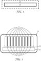
FIG. 1 is a schematic end view of a fiber matrix layer and an optional encapsulation layer that may be used in a thermal runaway barrier application. -
FIG. 2 is a schematic side view of a battery module of battery cells, with thermal runaway barriers disposed between adjacent battery cells. -
FIG. 3 is a schematic top view of a battery pack of battery modules, with thermal runaway barriers placed between adjacent battery modules and/or on the top of the battery modules. -
FIG. 4 is a photographic perspective view of a thermal runaway barrier encapsulated with an adhesive-backed organic polymeric layer with release liners and an expanding gas outlet/notch. -
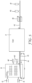
FIG. 5 is a schematic side view of a Dry-laid process for manufacturing a battery cell thermal runaway barrier, according to one embodiment of the present invention. -
FIG. 6 is a cross-sectional view of one embodiment of a thermal runaway barrier showing multiple expanding gas vent holes formed through the encapsulating film, according to one embodiment of the invention. -
FIG. 7 is a cross-sectional view of another embodiment of a thermal runaway barrier showing multiple expanding gas vent holes in the form of notches formed through the encapsulating film, according to another embodiment of the invention. -
FIG. 8 is a top plan view of an additional embodiment of a thermal runaway barrier with two different types of expanding gas vent holes formed through the encapsulation film. - In describing preferred embodiments of the invention, specific terminology is used for the sake of clarity. The invention, however, is not intended to be limited to the specific terms so selected, and each term so selected includes all technical equivalents that operate similarly.
- As used herein, the terms "preferred" and "preferably" refer to embodiments described herein that can afford certain benefits, under certain circumstances. However, other embodiments may also be preferred, under the same or other circumstances. Furthermore, the recitation of one or more preferred embodiments does not imply that other embodiments are not useful and is not intended to exclude other embodiments from the scope of the invention.
- As used herein and in the appended claims, the singular forms "a," "an," and "the" include plural referents unless the context clearly dictates otherwise. Thus, for example, reference to "a" or "the" component may include one or more of the components and equivalents thereof known to those skilled in the art. Further, the term "and/or" means one or all the listed elements or a combination of any two or more of the listed elements.
- It is noted that the term "comprises" and variations thereof do not have a limiting meaning where these terms appear in the accompanying description. Moreover, "a," "an," "the," "at least one," and "one or more" are used interchangeably herein. Relative terms such as left, right, forward, rearward, top, bottom, side, upper, lower, horizontal, vertical, and the like may be used herein and, if so, are from the perspective observed in the drawing. These terms are used only to simplify the description, however, and not to limit the scope of the invention in any way.
- Reference throughout this specification to "one embodiment," "certain embodiments," "one or more embodiments" or "an embodiment" means that a particular feature, structure, material, or characteristic described in connection with the embodiment is included in at least one embodiment of the invention. Thus, the appearances of the phrases such as "in one or more embodiments," "in certain embodiments," "in one embodiment" or "in an embodiment" in various places throughout this specification are not necessarily referring to the same embodiment of the invention. Where applicable, trade designations are set out in all uppercase letters.
- The term "and/or" means one or all of the listed elements or a combination of any two or more of the listed elements (e.g., preventing and/or treating an affliction means preventing, treating, or both treating and preventing further afflictions).
- As used herein, the term "or" is generally employed in its sense including "and/or" unless the content clearly dictates otherwise.
- Also herein, the recitations of numerical ranges by endpoints include all numbers subsumed within that range (e.g., 1 to 5 includes 1, 1.5, 2, 2.75, 3, 3.80, 4, 5, etc.).
- "Ambient conditions" means at 25°C and 101.3 kPa pressure.
- "Average" means number average, unless otherwise specified.
- "Continuous" means extending across a single, unified area along a given layer (a perforated sheet can be continuous);
- "Cure" refers to exposing to radiation in any form, heating, or allowing to undergo a physical or chemical reaction that results in hardening or an increase in viscosity.
- "Discontinuous" means extending across a plurality of discrete areas along a given layer, where the discrete areas are spaced apart from each other;
- "Size" refers to the longest dimension of a given object or surface.
- "Substantially" means to a significant degree, as in an amount of at least 50%, 60, 70, 80, 90, 95, 96, 97, 98, 99, 99.5, 99.9, 99.99, or 99.999%, or 100%.
- "Thickness" means the distance between opposing sides of a layer or multilayered article.
- The recitation of numerical ranges by endpoints includes all numbers subsumed within that range in increments commensurate with the degree of accuracy indicated by the end points of the specified range (e.g., for a range of from 1.000 to 5.000, the increments will be 0.001, and the range will include 1.000, 1.001, 1.002, etc., 1.100, 1.101, 1.102, etc., 2.000, 2.001, 2.002, etc., 2.100, 2.101, 2.102, etc., 3.000, 3.001, 3.002, etc., 3.100, 3.101, 3.102, etc., 4.000, 4.001, 4.002, etc., 4.100, 4.101, 4.102, etc., 5.000, 5.001, 5.002, etc. up to 5.999) and any range within that range, unless expressly indicated otherwise.
- The term "polymer" will be understood to include polymers, copolymers (e.g., polymers formed using two or more different monomers), oligomers and combinations thereof, as well as polymers, oligomers, or copolymers that can be formed in a miscible blend.
- The following Examples have been selected merely to further illustrate features, advantages, and other details of the invention. It is to be expressly understood, however, that while the Examples serve this purpose, the particular ingredients and amounts used as well as other conditions and details are not to be construed in a manner that would unduly limit the scope of this invention.
- Referring to
FIG. 1 , afiber matrix layer 10 useful in a thermal runaway barrier application contains nonwoven inorganic (i.e., nonmetallic), heat resistant fibrous insulation material, thermally insulative, nonmetallic inorganic particles, and an organic or inorganic binder. As used herein, nonmetallic means it is not a metal or metal alloy. Thefiber matrix layer 10 is encapsulated with anorganic polymeric layer 12. - Referring to
FIG. 2 , anexemplary battery module 20 includes an assembly ofbattery cells 22 and a plurality of thermalrunaway barriers 24. Each thermalrunaway barrier 24 is in the form of a singlefiber matrix layer 10, with anencapsulation 12, and that is made from the exemplary materials described herein. A thermalrunaway barrier 24 can be disposed betweenadjacent battery cells 22, between groups ofcells 22, or both, at one or more locations throughout thebattery module 20. Typically, thebattery module 20 rests above a coolingplate 26 and atray 28. - Referring to
FIG. 3 , anexemplary battery pack 30 includes a plurality ofbattery modules 20, which may each have itsown cooling plate 26 andtray 28 or all of themodules 20 may share thesame cooling plate 26 andtray 28. A thermalrunaway barrier 24, formed from the exemplary materials described herein, can be disposed between one or more or alladjacent battery modules 20, on the top of one or more or all of the battery modules 20 (see reference number 24'), or any combination of both. A thermalrunaway barrier 24 may also be dimensioned so as to cover the tops of all of thebattery modules 20. - Referring to
FIG. 4 , an exemplary thermalrunaway barrier 24 includes a single fiber matrix layer (not shown) encapsulated with anorganic polymeric layer 12 that covers both sides and the peripheral edge of the fiber matrix layer. In one embodiment, the major opposite faces of theencapsulating layer 12 are coated with an adhesive (e.g., a pressure sensitive adhesive) protected by correspondingrelease liners layer 12 includes one or more outlets or openings 18 (e.g., in the form of a notch) that allows air (e.g., hot air) or other gases to escape from inside theencapsulation 12, rather than cause theencapsulation 12 to swell and expand like a balloon, e.g., when the air trapped in theencapsulation 12 is heated to an elevated temperature (e.g., when the temperature of one or more of theadjacent battery cells 20 increases). - Referring to
FIG. 5 , a conventional dry-laid manufacturing equipment and processes can be used to manufacture thermalrunaway barriers 20 according to the invention. Examples of such equipment and processes can be found described inU.S. Pat. Nos. 9,580,848 (Henderson et al. 9,475,034 (Vincent et al. 7,491,354 (Anderson ), and6,808,664 (Falk et al. ). Such equipment can include a chamber or formingbox 40 with multiple feeder inlets, including aninlet 42 for feeding any desired combination of fibers, binder and particles into thebox 40, andmultiple inlets box 40. After the fibers are combined and mixed together with the other ingredients, the resulting nonwovenfibrous material 45 is deposited onto abelt 46 that conveys the material 45 into, through and out of a bakingoven 47 where the binder is cured at least so that thefibrous material 45 can be further processed. The resulting cured nonwoven fibrous material 45' is then die-cut, laser-cut, water-jet cut, or otherwise processed into individual nonwoven fiber layers 10 (not shown), which are each then processed at anencapsulation station 48, e.g., by having a polymeric film 12 (not shown) laminated to opposite sides of eachlayer 10. An optional hot melt adhesive or pressure sensitive adhesive can be applied to one or both sides of the encapsulate 12 at correspondingspray stations 49 and 49'. A protective release liner (not shown) can be subsequently applied to each adhesive surface. - Referring to
FIG. 6 , one embodiment of a thermalrunaway barrier 24 according to the invention includes one or more vent holes 52 formed through one or both layers of the encapsulatingfilm 12. The vent holes 52 can have any desired shape (e.g., circular, rectangular, oval, etc.), and preferably the vent holes 52 are formed through a portion of thefilm 12 located beyond the periphery of the encapsulatedfibrous layer 10 and still within the periphery of theencapsulation 12, while also providing a path for expanding gases (e.g., air) to escape out of the space containing thefibrous layer 10. The number, size and location of these vent holes 52 can vary as desired. - Referring to
FIG. 7 , another embodiment of a thermalrunaway barrier 24 according to the invention includes twovent holes 54, each in the form of a notch formed through the encapsulatingfilm 12. The vent holes 54 can have any desired shape (e.g., semicircular, rectangular, semioval, etc.), and preferably thenotches 54 are formed through a portion of thefilm 12 located beyond the periphery of the encapsulatedfibrous layer 10 and past the periphery of theencapsulation 12, while also providing a path for expanding gases (e.g., air) to escape out of the space containing thefibrous layer 10. The number, size and location of thesenotches 54 can vary as desired. - Referring to
FIG. 8 , an additional embodiment of a thermalrunaway barrier 24 according to the invention includes two different types of vent holes 52 and 54 formed through theencapsulation 12, like those described above relative toFIGS. 6 and 7 .Table 1: Test Materials Material Description Source AG Silica aerogel with a particle size of 100-700 micrometer and a pore size of 20 nanometers available under the designation ENOVA Aerogel IC3110 Cabot Corp, Boston, MA, United States EAF68 Aqueous polymer dispersed pressure sensitive adhesive available under the designation VINNAPAS EAF 68 Vinyl Acetate Ethylene Wacker Chemie AG, Miinchen, Germany EVERM Expanded vermiculite Sun Gro, Agawam, MA, United States EXP Sodium silicate intumescent powder available under the trade designation "EXPANTROL" 3M Company, St. Paul, MN, United States EXPERL Expanded perlite available under the designation EUROCELL 300 Europerl, Pölten, Austria FB Acrylic water-based spray adhesive available under the trade designation "FASTBOND" 4224 NF 3M Company FS Fumed silica with an average particle size of 0.2 - 0.3 micrometers available under the trade designation CAB-O-SIL H-5 Cabot Corp, Boston, MA, United States H2345 Hot melt pressure sensitive adhesive available under the designation THERMOGRIP H2345-E71 Bostik, Inc, Milwaukee, WI. United States K1 Soda-lime-borosilicate hollow glass microspheres with a density of 0.125 g/cc and a median particle size of 65 micrometer available under the designation Glass Bubbles K1 3M Company LDM Alkaline earth silicate fiber with a mean fiber diameter of 3.0-3.5 micrometer available under the designation SAFFIL LDM Unifrax, Tonawanda, NY, United States PA Copolyamide powder adhesive with a granular size of 100-500 micrometer available under the designation 5350 Shaetti AG, Wallisellen, Switzerland PERL Raw, unexpanded perlite AGStein Aktiengesellschaft für Steinindustrie, Neuwied, Germany PP 0.02-millimeter polypropylene transparent film Charter-Nex Films, Superior, WI, United States SUM Alkaline earth silicate fibers, mean fiber diameter of 3 - 4 micrometers, available under the trade designation NUTEC Supermag Nutec Fibratec, S.A. de C.V., Mexico SW+ Alkaline earth silicate fibers with a mean fiber diameter of 2.5-3.4 micrometers available under the trade designation "SUPERWOOL PLUS" Morgan Advanced Materials, Windsor, United Kingdom T255 Polyester/polyethylene bi-component staple fibers, 1.3 dtex and 6-millimeter length available under the trade designation T255 Trevira GmbH, Bobingen, Germany VERM1 Vermucilite, 0.3 - 0.8 mm particle size Cometals, Inc, New York, NY, United States VERM2 Vermucilite 0.3 - 1.0 mm particle size Cometals, Inc, New York, NY, United States VERM3 Vermucilite 3.0 - 8.0 mm particle size Cometals, Inc, New York, NY, United States WDS Microporous inorganic silicate insulation available under the designation WDS® Morgan Advanced Materials - In an MTS Insight 5 kN tensile test machine (obtained from MTS Insight of Eden Prairie, MN, United States), a bottom platen was heated to 600°C, and a sample was placed on top of it. The upper platen, with a thermocouple embedded, was lowered such that the distance between the two platens was at 1.6 mm. The temperature increase at the cold-side was recorded with respect to time (continuously) until it reached 900 seconds (15 minutes).
- In a 10 kN tensile test machine (obtained from ZWICKROELL of Ulm, Germany), a top platen was heated to 600°C and a sample was placed on a bottom platen with a thermocouple embedded set at ambient temperature. A heat shield was used to cover the sample to ensure that it stayed at ambient temperature. The heat shield was then removed, and the upper platen was lowered with pressure held at 1 MPa. The time the sample took reach a temperature of 150°C (302°F), designated t(150°C), was recorded.
- The methods of ASTM273C 273M were followed. A five-minute shear speed was used.
- Thermal conductivity measurements values were obtained using a Thermal Constants Analyzer, Model TPS 2500S obtained from Hot Disk® AB of Goteborg, Sweden. Measurements were taken by choosing the Isotropic/Bulk (Type I) module within the software. The measurements were run using a Kapton 5465 sensor (Hot Disk®) having a diameter of 3.2 mm. As specified by the manual, the samples should have a lateral dimension that is 1.5 to 2.0 times the radius of the sensor. The sample thickness should also be equivalent or greater than the radius of the sensor. To ensure that the thickness was sufficiently greater than the radius of the sensor, three to four layers of a sample were stacked on each side of the sensor and a small pressure was applied to ensure that layers were all in contact with one another.
- Specified parameters were 1) measurement time in seconds and 2) heating power in mW. The sample temperature was inputted as the ambient room temperature. The measurement was then executed as defined in the TPS Manual.
- The results were analyzed by clicking on "Calculate" within the software and selecting the "Standard Analysis" option. After the measurement, several graphs were presented by the software, including the "Transient" graph and the "Residual" graph. The transient graph displays the temperature increase of the sensor during the heating of the sample up to 200 points. The first pass at analyzing the results will start at
point 10 and include everything up to point 200 on the transient. If the residual graph does not look like a random scatter of points, a smaller subset of datapoints was used for the analysis. This was done by trimming points from the beginning and end of the measurement. As a rule, the result was not reliable if less than 50 points are used in the analysis. In addition to satisfying the quality of the residual plot, several other numerical requirements were defined including "probing depth (PD)", "temperature increase (TI)", "total to characteristic time (TCT)", and "mean deviation (MD)" as specified in the manual. For these specifications: the PD must be less than the thickness of the sample, the TI must be between 0.4 K and 4.0 K, the TCT must be between 0.33 and 1.0, and the MD must be a magnitude of 10-4 or better. If these five criteria were not met, the heating power and measurement times were adjusted. The settings were iterated until an accurate measurement was made, where accuracy was defined by satisfying all the numerical requirements laid out in the manual. Thermal conductivity values in W/m·K were measured and recorded for tested samples. - For Examples 1, 3, and 5-7, combinations of staple fibers by weight percent (as identified in Table 2) were weighed and premixed by hand before placing on top of a feeding belt. The fiber material was processed (i.e., fed from the top) through an air-laid processer, like that disclosed in
US Patent No. 7,491,354 , where the fibers were opened and dispersed into an air stream, then collected on a screen belt. Details of such air-laid processing apparatus and methods of using such apparatus in forming air-laid webs can be found described inU.S. Pat. Nos. 9,580,848 (Henderson et al. 9,475,034 (Vincent et al. 7,491,354 (Anderson ), and6,808,664 (Falk et al. ). Fillers by weight percent (as identified in Table 2) were top or side fed into the chamber or forming box of the air-laid processor. A volumetric feeder coupled with an air-driven horn was used to distribute the fillers into the web uniformly. The sample was then sent through a forced-air convection oven at 143.3°C (290°F) at a speed of 1.1 m/min. - For Examples 2 and 4, the process described in Example 1 of
U.S. Pat. No. 5,869,010 (Langer ) was followed. Samples were assembled containing fibers and fillers by weight percent as identified in Table 2 rather than the materials identified inU.S. Pat. No. 5,869,010 . - For Example 8, Example A of
U.S. Pat. No. 9,399,864 (Samanta et al. Table 2: Sample Compositions (Weight Percent) SW+ LDM T255 EAF68 PA AG K1 WDS EXP EX1 20 20 16 0 4 40 0 0 0 EX2 0 62 0 8 0 0 30 0 0 EX3 20 20 16 0 4 0 0 40 0 EX4 0 52 0 8 0 0 0 0 40 CE1 35 35 30 0 0 0 0 0 0 EX5 15 15 30 0 0 40 0 0 0 CE2 92 0 8 0 0 0 0 0 0 EX6 72 0 8 0 0 20 0 0 0 EX7 52 0 8 0 0 40 0 0 0 EX8 59.5 0 2.5 8 0 30 0 0 0 Table 3: Hot-side/Cold-side Temperature Test Results (Basis Weight = 600 gsm) in Celsius (°C) Time (Minutes) EX1 EX2 EX3 EX4 CE1 EX5 CE2 EX6 EX7 EX8 0 22.0 22.0 22.0 22.0 22.0 22.0 33.9 24.3 29.5 35.0 1 45.9 67.3 56.3 81.0 68.9 48.6 53.4 46.8 44.5 58.0 2 63.1 87.3 78.3 103.0 94.7 67.8 68.8 62.6 55.5 73.7 3 76.9 103.8 95.6 120.3 114.0 80.7 80.9 75.4 64.2 87.1 4 88.0 117.5 108.6 136.5 129.0 92.3 90.4 85.6 71.1 98.0 5 96.7 127.1 118.8 146.6 140.7 101.6 94.5 90.0 74.0 106.7 6 104.4 134.6 126.5 155.3 150.5 109.5 101.6 97.2 79.3 113.9 7 110.0 140.8 133.1 162.1 158.0 115.4 110.3 105.8 85.5 120.1 8 115.3 145.7 138.5 168.1 164.6 119.6 114.9 110.2 88.8 125.3 9 119.2 150.0 143.1 173.0 169.9 124.6 118.9 113.9 91.7 129.7 10 122.6 153.7 147.0 177.3 174.5 128.1 122.2 117.0 94.1 133.6 11 125.7 157.0 150.5 181.3 178.5 131.5 125.2 119.7 96.1 137.0 12 128.4 159.8 153.4 184.5 181.9 131.9 127.6 121.9 97.8 139.9 13 130.8 162.4 156.1 187.5 184.9 140.2 129.8 124.0 99.3 142.6 14 132.8 164.6 158.6 190.0 187.5 137.7 131.8 125.8 100.6 145.0 15 134.7 166.5 160.8 192.0 189.9 141.2 133.6 127.4 101.8 147.1 - The `General Procedure for Preparing Fibrous Sheet' as described in
U.S. Patent Application No. 2010/0115900 with material substitution as identified in Table 4 was followed. Tap water (3 liters, 18° C.) and 60 grams (g) of inorganic fibers and cleaned to a shot content of less than 50 percent by weight) were added to a GT800 Classic blender (obtained from Rotor Lips Ltd, Uetendorf, Switzerland). The blender was operated on low speed for five seconds. The resultant slurry was rinsed into a RW16 mixing container equipped with a paddle mixer (obtained from IKA-Werke GmbH, Staufen, Germany) using one liter of tap water (18° C.). The slurry was diluted with an additional one liter of tap water (18° C.). The diluted slurry was mixed at medium speed to keep solids suspended. Defoaming agent (obtained under the trade designation "FOAMASTER 111" (0.3 g) from Henkel, Edison, N.J.) and ethylene-vinyl acetate terpolymer latex (obtained under the trade designation "AIRFLEX 600BP" (6.0 g, 55 percent by weight solids) from Air Products were added. Flocculent is added dropwise in amounts as indicated in Table 4. Thermally insulative particles were then added as indicated in Table 4. The mixer speed was increased and mixing continued for from 1 to 5 minutes. The paddle mixer was removed, and the slurry was poured into a 20 cm x 20 cm (8 inches x 8 inches) sheet former (obtained from Williams Apparatus Co, Watertown, NY, United States) and drained. The surface of the drained sheet was rolled with a rolling pin to remove excess water. Then, the sheet was pressed between blotter papers at a surface pressure of 90-97 kPa (13-14 psi) for five minutes. The sheet was then dried at 150° C. in a forced air oven for 10-15 minutes and allowed to equilibrate overnight while exposed to the ambient atmosphere. The thickness and basis weight of the samples were measured at a constant pressure of 4.9 kPa, and are recorded in Table 5. For Examples 15 - 25 (EX15 - EX25) the vermiculite material used in these samples were either pre-heated to permanently pre-expand the vermiculite, before being used to make the samples, or post-heated to permanently post-expand the vermiculite, after the samples were made, at specific time and temperature conditions. For EX21, the vermiculite was pre-heated at 300°C for 6 hours before sample assembly. For EX22 and EX23, the vermiculite was heated at 450°C for 30 minutes after sample assembly. For EX24, the vermiculite was pre-heated at 500°C for 30 minutes before sample assembly. For EX25 EX33, and EX34, the vermiculite in the sample was pre-heated at 1000°C for 30 minutes before sample assembly.Table 4: Sample Compositions (Weight Percent) SW+ SUM EAF68 VERM1 EXVERM PERL EXPERL CE3 95 0 5 0 0 0 0 CE4 90 0 10 0 0 0 0 CE5 90 0 10 0 0 0 0 CE6 90 0 10 0 0 0 0 CE7 90 0 10 0 0 0 0 CE8 90 0 10 0 0 0 0 EX9 50 0 5 45 0 0 0 EX10 50 0 5 45 0 0 0 EX11 50 0 5 45 0 0 0 EX12 50 0 5 45 0 0 0 EX13 50 0 5 45 0 0 0 EX14 50 0 5 45 0 0 0 EX15 0 50 5 0 45 0 0 EX16 0 50 5 0 45 0 0 EX17 0 50 5 0 45 0 0 EX18 0 50 5 22.5 22.5 0 0 EX19 65 0 5 0 30 0 0 EX20 65 0 5 0 30 0 0 EX21 50 0 5 0 45 0 0 EX22 50 0 5 0 45 0 0 EX23 50 0 5 0 45 0 0 EX24 50 0 5 0 45 0 0 EX25 50 0 5 0 45 0 0 EX26 0 23 8 0 0 0 69 EX27 0 23 8 0 0 0 69 EX28 0 23 8 0 0 0 69 EX29 0 47 6 0 0 0 47 EX30 0 22 6 0 0 0 72 EX31 0 70 5 0 0 25 0 EX32 0 20 5 0 0 75 0 EX33 65 0 5 0 30 0 0 EX34 65 0 5 0 30 0 0 Table 5: Hot-side/Cold-side Temperature Test Results Thickness Basis Weight t(150°C) (mm) (gsm) (seconds) CE3 4.17 643 297 CE4 2.68 413 162 CE5 2.14 319 122 CE6 1.16 207 63 CE7 1.23 193 63 CE8 1.04 161 52 EX9 4.17 643 297 EX10 2.74 614 182 EX11 2.53 530 154 EX12 1.73 394 111 EX13 1.42 310 89 EX14 1.23 252 73 EX15 4.70 529 126 EX16 2.15 437 109 EX17 1.70 478 113 EX18 1.95 499 105 EX19 4.22 453 120 EX20 5.45 606 197 EX21 1.85 362 129 EX22 2.87 490 205 EX23 2.68 508 207 EX24 1.92 341 127 EX25 4.40 514 197 EX26 4.59 208 208 EX27 3.25 120 120 EX28 3.74 186 186 EX29 3.82 115 115 EX30 2.59 100 100 EX31 2.00 540 97 EX32 2.62 1197 139 EX33 2.80 450 116 EX34 3.42 550 141 - PP was laminated onto a sample as assembled in Example 5. Hand samples were hot pressed at 132°C (270°F) and 200 kPa on both sides. The edges were manually sealed using an impulse sealer which was at 149°C (300°F), and heated for 2 seconds, cooled for 10 seconds, with all the steps being conducted under a compressive force of 524 kPa (76 psi) pressure. The PP film thickness was 0.02 mm (1 mil). The 600 gsm sample underwent Shear Strength testing and the results are represented in Table 6.
- Hot melt adhesive H2345 was applied to the sample in Example 35 using a Nordson Altablue Gridmelter with a 15.24 cm (6 inch) melt blown adhesive die. The adhesive was heated at 193°C (380°F) and sprayed on to the web at 206.8 kPa (30 psi) air pressure and 20 RPM pump rate. The 600 gsm sample underwent Shear Strength testing and the results are represented in Table 6.
- FB was spray coated onto a sample as assembled in Example 35 using a ACCUSPRAY ONE Spray Gun System with PPS obtained from 3M Company of St. Paul, MN, United States. Hand samples were spray coated on one side and then flipped to coat the other side. The 600 gsm sample underwent Shear Strength testing and the results are represented in Table 6.
- PKHH Phenoxy Resin obtained from Gabriel Performance Products of Akron, OH, United States was dissolved in a 50% solution of methyl ethyl ketone (MEK) to create an adhesive. The MEK was evaporated at room temperature for 60 minutes. Two coatings of the adhesive were applied onto one side of a 0.076 mm (3 mil) PET film obtained from Dupont of Wilmington, DE, United States. Two coatings of the adhesive were applied onto a side of another 0.076 mm (3 mil) PET film. The thickness of the adhesive coating was 0.036 mm (1.4 mil). The adhesive coated PET sample films were placed onto the top and bottom side of a sample as assembled in Example 5. The 600 gsm sample underwent Shear Strength testing and the results are represented in Table 6.
Table 6: Encapsulated Sample Test Results Shear Strength Example MPa EX35 0.27 EX36 0.27 EX37 0.26 EX38 1.28 - Samples were assembled using procedures described in Examples 9-16 with the materials identified in Table 7. The thickness and basis weight of the samples were measured at a constant pressure of 4.9 kPa and are recorded in Table 8. The samples underwent HCST2 testing, and the results are represented in Table 8.
Table 7: Sample Compositions (Weight Percent) SW+ EAF68 VERM2 VERM3 EX39 50 5 45 0 EX40 50 5 0 45 Table 8: Hot-side/Cold-side Temperature Test Results Thickness Basis Weight t(150°C) (mm) (gsm) (seconds) EX39 1.78 405 84.7 EX40 2.65 723 413.8 - Combinations of staple fibers by basis weight (as identified in Table 9) were weighed and processed through an air-laid processer. Details of the apparatus and methods of using the apparatus in forming air-laid webs are described in
U.S. Pat. Nos. 9,580,848 (Henderson et al. 9,475,034 (Vincent et al. 7,491,354 (Anderson ), and6,808,664 (Falk et al. ). The combined staple fibers were then processed again by the air-laid processor and a fumed silica filler was directly fed into the chamber of the air-laid processor by basis weight (as identified in Table 2). A screw feeder was used to distribute the fillers into the web uniformly. The web was sent through a forced-air convection oven at 148.89°C (300°F) at a speed between 0.25 m/min and 1.5 m/min. The thickness of the samples was between 0.5 to 15 mm. - The webs were then densified to a specified gap thickness using a hot press. Polytetrafluoroethylene (PTFE) coated fiberglass fabric sheets (obtained from McMaster-Carr of Elmhurst, IL. United States) were placed on both sides of the samples and the samples were placed between two hot plates maintained at a temperature of 148.89°C (300°F). Pressure was applied for 30 to 120 seconds to activate the bi-component fibers (T255). The densified sample was then immediately placed between two plates maintained at room temperature under a pressure for 30 to 120 seconds, to set the web to the desired thickness.
Table 9: Sample Compositions (gsm) SW+ T255 FS EX41 256 64 80 EX42 192 48 160 EX43 128 32 240 EX44 384 96 160 EX45 288 72 320 EX46 192 48 480 EX47 640 160 200 EX48 480 120 400 EX49 480 120 400 EX50 480 120 400 EX51 480 120 400 EX52 480 120 400 EX53 480 120 400 EX54 320 80 600 EX55 768 192 240 EX56 576 144 480 EX57 384 96 720 - The samples underwent HCST2 testing, and the results are represented in Table 10. The actual thickness of the samples was measured by ASTM D5736-95 with the fiberglass fabric sheets removed. The plate pressure was calibrated at 0.002 psi (13.790 Pascal).
Table 10: Hot-side/Cold-side Temperature Test Results Target Thickness Actual Thickness Target Basis Weight Actual Basis Weight t(150°C) (mm) (mm) (gsm) (gsm) (seconds) EX41 1.00 0.99 400 387 35 EX42 1.00 0.97 400 337 53 EX43 1.00 1.09 400 324 287 EX44 2.00 1.94 800 547 277 EX45 2.00 1.96 800 697 737 EX46 2.00 2.09 800 657 3600 EX47 3.00 2.92 1000 837 230 EX48 3.00 2.80 1000 743 3600 EX49 2.00 2.02 1000 953 799 EX50 3.00 2.83 1000 930 3600 EX51 4.00 3.56 1000 857 3600 EX52 6.00 5.94 1000 907 3600 EX53 8.00 7.78 1000 933 3600 EX54 3.00 2.80 1000 707 3600 EX55 4.00 3.96 1200 1077 685 EX56 4.00 3.90 1200 1097 3600 EX57 4.00 3.90 1200 873 3600 - Densities of 1000 gsm samples containing 40% fumed silica (represented in EX48 - EX53) were computed by dividing the actual basis weight (gsm) by the actual thickness (mm). Density and the cold side temperature recorded after 3600 seconds of HSCT2 testing for EX48 - EX53 is represented in Table 11. The table is organized in escending order by measured cold side temperatures.
Table 11: Density vs. Cold Side Temperature Density Cold Side Temperature (gsm/mm) °C EX49 472 180.9 EX51 241 141.7 EX53 120 140.2 EX52 153 137.3 EX50 329 134.6 EX48 265 130.8 Table 12: Thermal Conductivity Test Results Thermal Conductivity W/m·K EX47 0.0531 EX49 0.0708 EX50 0.0481 EX52 0.0508 - Surprisingly, it has been found that fumed silica has a higher thermal conductivity than silica aerogel. It is believed that the thermal conductivity of the nonwoven fibrous thermal insulation without the fumed silica particles (i.e., the fiber matrix) is lower than the same fiber matrix with the fumed silica particles.
- This invention may take on various modifications and alterations without departing from the scope of the claims. For example, it is believed that microwave heating can be used to irreversibly or permanently expand the particles made from intumescent materials. It is also believed that using microwave energy, rather than baking in an oven, can result in a more uniform expansion of the intumescent particles within the fiber matrix. Accordingly, this invention is not limited to the above-described but is to be controlled by the limitations set forth in the following embodiments. This invention may be suitably practiced in the absence of any element not specifically disclosed herein.
Claims (10)
- A thermal runaway barrier operatively adapted for being disposed between battery cells of a battery assembly and for at least significantly slowing down a thermal runaway event within the battery assembly, said thermal runaway barrier consisting essentially of:a single-layer of a nonwoven fibrous thermal insulation comprising a fiber matrix of inorganic fibers, thermally insulative inorganic particles dispersed within the fiber matrix, and a binder dispersed within the fiber matrix so as to hold together the fiber matrix; andan organic encapsulation layer;wherein the layer of nonwoven fibrous thermal insulation is encapsulated by the organic encapsulation layer, andwherein the organic encapsulation layer has at least one vent hole formed therethrough that is located and sized to allow gas contained within the thermal runaway barrier to escape from the organic encapsulation, such that the structural integrity of the organic encapsulation layer is kept intact, during a thermal runaway event.
- The thermal runaway barrier according to claim 1, wherein the layer of nonwoven fibrous thermal insulation contains an amount of thermally insulative inorganic particles in the range of from as low as about 10% up to as high as about 60 %, by weight of the layer of nonwoven fibrous thermal insulation.
- The thermal runaway barrier according to claim 1 or 2, wherein the layer of nonwoven fibrous thermal insulation contains an amount of organic binder in the range of from as low as about 2.5% up to as high as about 10.0%, by weight of the layer of nonwoven fibrous thermal insulation.
- The thermal runaway barrier according to any one of claims 1 to 3, wherein the layer of nonwoven fibrous thermal insulation has an installed thickness in the range of from about 0.5 mm up to less than 5.0 mm.
- The thermal runaway barrier according to any one of claims 1 to 4, wherein the layer of nonwoven fibrous thermal insulation has a basis weight in the range of from as low as about 250 g/m2 and up to as high as about 1000 g/m2.
- The thermal runaway barrier according to any one of claims 1 to 5, wherein the thermally insulative inorganic particles comprise particles of one or any combination of the materials selected from the group consisting of inorganic aerogel, xerogel, hollow or porous ceramic microspheres, unexpanded vermiculite, irreversibly or permanently expanded vermiculite, fumed silica, otherwise porous silica, irreversibly or permanently expanded or unexpanded perlite, pumicite, irreversibly or permanently expanded clay, diatomaceous earth, titania and zirconia.
- The thermal runaway barrier according to any one of claims 1 to 6, wherein the at least one vent hole provides an exit opening through the organic encapsulation layer having an opening area in the range of from about 2 mm2 up to about 15 mm2.
- The thermal runaway barrier according to any one of claims 1 to 7, wherein the thermal runaway barrier has a top edge, a bottom edge and opposite side edges, and the at least one vent hole is located along the periphery of one or both opposite side edges.
- The thermal runaway barrier according to any one of claims 1 to 7, wherein the layer of nonwoven fibrous thermal insulation has a peripheral edge, and the organic encapsulation layer is sealed around the peripheral edge, and wherein the at least one vent hole is formed through the encapsulation layer interior to a side edge of the encapsulation layer and adjacent to the nonwoven thermal insulation.
- A battery cell module for an electric vehicle, said battery cell module comprising:a plurality of battery cells disposed in a housing; anda plurality of thermal runaway barriers according to any one of claims 1 to 9,wherein the battery cells are lined up in a row, with one thermal runaway barrier being disposed between each pair of adjacent battery cells.
Priority Applications (1)
| Application Number | Priority Date | Filing Date | Title |
|---|---|---|---|
| EP24166024.0A EP4386122B1 (en) | 2020-07-30 | 2021-07-30 | Battery cell thermal runaway barrier |
Applications Claiming Priority (2)
| Application Number | Priority Date | Filing Date | Title |
|---|---|---|---|
| US202063058863P | 2020-07-30 | 2020-07-30 | |
| PCT/IB2021/056993 WO2022024076A1 (en) | 2020-07-30 | 2021-07-30 | Battery cell thermal runaway barrier |
Related Child Applications (2)
| Application Number | Title | Priority Date | Filing Date |
|---|---|---|---|
| EP24166024.0A Division EP4386122B1 (en) | 2020-07-30 | 2021-07-30 | Battery cell thermal runaway barrier |
| EP24166024.0A Division-Into EP4386122B1 (en) | 2020-07-30 | 2021-07-30 | Battery cell thermal runaway barrier |
Publications (3)
| Publication Number | Publication Date |
|---|---|
| EP4189768A1 EP4189768A1 (en) | 2023-06-07 |
| EP4189768C0 EP4189768C0 (en) | 2024-05-01 |
| EP4189768B1 true EP4189768B1 (en) | 2024-05-01 |
Family
ID=77265135
Family Applications (4)
| Application Number | Title | Priority Date | Filing Date |
|---|---|---|---|
| EP24166024.0A Active EP4386122B1 (en) | 2020-07-30 | 2021-07-30 | Battery cell thermal runaway barrier |
| EP24170442.8A Active EP4401200B1 (en) | 2020-07-30 | 2021-07-30 | Battery cell thermal runaway barrier |
| EP21752219.2A Active EP4189768B1 (en) | 2020-07-30 | 2021-07-30 | Battery cell thermal runaway barrier |
| EP21752225.9A Active EP4189769B1 (en) | 2020-07-30 | 2021-07-30 | Battery cell thermal runaway barrier |
Family Applications Before (2)
| Application Number | Title | Priority Date | Filing Date |
|---|---|---|---|
| EP24166024.0A Active EP4386122B1 (en) | 2020-07-30 | 2021-07-30 | Battery cell thermal runaway barrier |
| EP24170442.8A Active EP4401200B1 (en) | 2020-07-30 | 2021-07-30 | Battery cell thermal runaway barrier |
Family Applications After (1)
| Application Number | Title | Priority Date | Filing Date |
|---|---|---|---|
| EP21752225.9A Active EP4189769B1 (en) | 2020-07-30 | 2021-07-30 | Battery cell thermal runaway barrier |
Country Status (5)
| Country | Link |
|---|---|
| US (3) | US20230275289A1 (en) |
| EP (4) | EP4386122B1 (en) |
| JP (2) | JP7837314B2 (en) |
| CN (2) | CN116097500B (en) |
| WO (3) | WO2022024076A1 (en) |
Families Citing this family (38)
| Publication number | Priority date | Publication date | Assignee | Title |
|---|---|---|---|---|
| US20220123386A1 (en) * | 2019-09-05 | 2022-04-21 | Samsung Sdi Co., Ltd. | Energy storage module |
| EP4386122B1 (en) * | 2020-07-30 | 2025-11-05 | 3M Innovative Properties Co. | Battery cell thermal runaway barrier |
| CN116848301B (en) * | 2021-03-29 | 2025-10-03 | 巴川集团股份有限公司 | Inorganic fiber sheets |
| EP4178012B1 (en) * | 2021-11-09 | 2026-04-29 | SK On Co., Ltd. | Battery cell stack and manufacturing method thereof |
| DE102021132072A1 (en) | 2021-12-06 | 2023-06-07 | Carl Freudenberg Kg | energy storage system |
| CA3253243A1 (en) | 2022-02-24 | 2023-08-31 | Unifrax I Llc | Fiber-containing fire protection material |
| EP4276431A1 (en) | 2022-05-10 | 2023-11-15 | Airbus Operations | Thermal indicating device |
| JP7820240B2 (en) * | 2022-05-27 | 2026-02-25 | イビデン株式会社 | Heat transfer suppression sheet and assembled battery |
| JP7414888B2 (en) * | 2022-05-27 | 2024-01-16 | イビデン株式会社 | Heat transfer suppression sheet and assembled battery |
| JP7364742B1 (en) * | 2022-05-27 | 2023-10-18 | イビデン株式会社 | Heat transfer suppression sheet and assembled battery |
| US20250112336A1 (en) * | 2022-05-27 | 2025-04-03 | Electric Power Systems, Inc. | Interconnected battery connection devices and methods of operation |
| JP2023174127A (en) * | 2022-05-27 | 2023-12-07 | イビデン株式会社 | Heat transfer suppression sheet and assembled battery |
| WO2023230251A1 (en) | 2022-05-27 | 2023-11-30 | Cabot Corporation | Aerogel composition for thermal insulation |
| WO2023239306A1 (en) * | 2022-06-10 | 2023-12-14 | Aerogel R&D Pte. Ltd. | Intumescent sheet used in an electric vehicle battery for thermal runaway management |
| CN119403677A (en) * | 2022-06-21 | 2025-02-07 | 3M创新有限公司 | Products with pressure management and thermal insulation properties |
| JP7436582B1 (en) | 2022-08-03 | 2024-02-21 | イビデン株式会社 | Heat transfer suppression sheet and assembled battery |
| EP4316900B1 (en) * | 2022-08-05 | 2025-02-26 | Autoneum Management AG | Flame shield for a battery of an electric vehicle and battery housing comprising it |
| WO2024059682A1 (en) * | 2022-09-16 | 2024-03-21 | Cabot Corporation | Aerogel composition for thermal insulation |
| JP2025538685A (en) | 2022-12-02 | 2025-11-28 | スリーエム イノベイティブ プロパティズ カンパニー | Flat web and battery module including same |
| WO2024142669A1 (en) * | 2022-12-27 | 2024-07-04 | タイガースポリマー株式会社 | Secondary battery |
| JP2026508117A (en) * | 2023-02-20 | 2026-03-10 | 鞏義市泛鋭▲い▼輝復合材料股▲ふん▼有限公司 | Heat insulating material and its manufacturing method, heat insulating member, heat insulating product, battery and electrical equipment |
| KR102843088B1 (en) * | 2023-04-12 | 2025-08-08 | 삼성에스디아이 주식회사 | Aerogel composition for battery insulation sheet, manufacturing method thereof, battery insulation sheet formed using the same, and manufacturing method thereof |
| CN120936487A (en) | 2023-04-14 | 2025-11-11 | 3M创新有限公司 | Articles including meltblown microfibers and fire barrier particles and related methods |
| KR20260008121A (en) * | 2023-05-16 | 2026-01-15 | 오르클리, 에스. 쿱. | non-woven mat |
| DE102023114343A1 (en) * | 2023-05-31 | 2024-12-05 | Elringklinger Ag | cell separator, battery module and manufacturing process |
| KR20260018911A (en) * | 2023-06-05 | 2026-02-09 | 캐보트 코포레이션 | flexible insulating material |
| EP4480695A1 (en) * | 2023-06-19 | 2024-12-25 | Saint-Gobain Adfors SA | Insulation element |
| US12592447B2 (en) | 2023-07-24 | 2026-03-31 | Ford Global Technologies, Llc | Partitioned traction battery pack and battery pack partitioning method |
| EP4530059B1 (en) * | 2023-09-26 | 2026-02-18 | Gongyi Van-Research Innovation Composite Material Co., Ltd. | Thermal insulation element for battey and method for making the same |
| WO2025111152A1 (en) | 2023-11-20 | 2025-05-30 | Cabot Corporation | Silica particle composition for thermal insulation |
| WO2025186643A1 (en) | 2024-03-04 | 2025-09-12 | 3M Innovative Properties Company | Thermal barrier |
| WO2025191405A1 (en) * | 2024-03-14 | 2025-09-18 | 3M Innovative Properties Company | Nonwoven substrate with discrete foam penetrations |
| WO2025206581A1 (en) * | 2024-03-26 | 2025-10-02 | 주식회사 케이씨씨 | Sheet for preventing thermal runaway of battery, and battery cell assembly comprising same |
| WO2025228971A1 (en) * | 2024-05-02 | 2025-11-06 | Nies Klaus Dieter | Battery arrangement with spacer textile |
| CN118441409A (en) * | 2024-07-08 | 2024-08-06 | 成都硕屋科技有限公司 | Preparation method of aerogel heat insulation composite material |
| WO2026018116A1 (en) * | 2024-07-17 | 2026-01-22 | 3M Innovative Properties Company | Thermal barrier |
| KR20260021857A (en) * | 2024-08-06 | 2026-02-19 | 주식회사 케이씨씨 | Flame retardant coating composition and battery thermal runaway prevention sheet including the same |
| WO2026083178A1 (en) * | 2024-10-14 | 2026-04-23 | 3M Innovative Properties Company | Pleated thermal insultative layer |
Family Cites Families (38)
| Publication number | Priority date | Publication date | Assignee | Title |
|---|---|---|---|---|
| US5591505A (en) * | 1995-06-07 | 1997-01-07 | Owens-Corning Fiberglas Technology, Inc. | Fibrous insulation product having inorganic binders |
| JPH11509510A (en) | 1995-06-30 | 1999-08-24 | ミネソタ・マイニング・アンド・マニュファクチャリング・カンパニー | Expansion sheet material |
| US6043169A (en) * | 1997-09-04 | 2000-03-28 | Johns Manville International, Inc. | Nonwoven RF reflecting mats and method of making |
| US6008147A (en) * | 1998-05-28 | 1999-12-28 | Johns Manville International, Inc. | Fiber glass mat for laminating to foam, foam laminate precursor, foam laminate, and methods of making the mat and the foam laminate |
| SE523021C2 (en) | 2000-05-22 | 2004-03-23 | Sca Hygiene Prod Ab | Method for forming an air-laid fiber web |
| EP1469939A1 (en) * | 2002-01-29 | 2004-10-27 | Cabot Corporation | Heat resistant aerogel insulation composite and method for its preparation; aerogel binder composition and method for its preparation |
| JP4620057B2 (en) | 2003-11-07 | 2011-01-26 | フォームファイバー デンマーク エーピーエス | Fiber distribution device for dry forming of fibrous products |
| WO2007011750A2 (en) * | 2005-07-15 | 2007-01-25 | Aspen Aerogels, Inc. | Secured aerogel composites and method of manufacture thereof |
| US7709069B2 (en) * | 2005-12-14 | 2010-05-04 | M & Q Packaging Corporation | High temperature venting bags |
| US8453393B2 (en) * | 2006-08-25 | 2013-06-04 | Raytheon Company | Encapsulated and vented particulate thermal insulation |
| CN102154915B (en) | 2007-02-19 | 2014-04-23 | 3M创新有限公司 | Flexible fibrous material, pollution control device, and methods of making the same |
| DE102007042554B4 (en) * | 2007-09-07 | 2017-05-11 | Carl Freudenberg Kg | Nonwoven with particle filling |
| US7736799B1 (en) * | 2009-07-17 | 2010-06-15 | Tesla Motors, Inc. | Method and apparatus for maintaining cell wall integrity during thermal runaway using an outer layer of intumescent material |
| US8541126B2 (en) | 2009-08-31 | 2013-09-24 | Tesla Motors, Inc. | Thermal barrier structure for containing thermal runaway propagation within a battery pack |
| WO2011130056A2 (en) | 2010-04-13 | 2011-10-20 | 3M Innovative Properties Company | Inorganic fiber webs and methods of making and using |
| PL2561128T3 (en) | 2010-04-22 | 2015-08-31 | 3M Innovative Properties Co | Nonwoven fibrous webs containing chemically active particulates and methods of making and using same |
| US8932739B2 (en) * | 2010-08-04 | 2015-01-13 | Tesla Motors, Inc. | Battery pack configuration to reduce hazards associated with internal short circuits |
| WO2012046475A1 (en) * | 2010-10-08 | 2012-04-12 | 日東電工株式会社 | Thermally functional flame-retardant polymer member |
| US9196939B2 (en) * | 2011-11-02 | 2015-11-24 | GM Global Technology Operations LLC | Method for thermal management and mitigation of thermal propagation for batteries using a graphene coated polymer barrier substrate |
| DK2798108T3 (en) | 2011-12-30 | 2017-02-13 | 3M Innovative Properties Co | APPARATUS AND METHODS FOR MANUFACTURING NON-WOVEN FIBER FLOORS |
| WO2014150310A1 (en) | 2013-03-15 | 2014-09-25 | Cabot Corporation | Aerogel blanket and method of production |
| CA2947765A1 (en) | 2014-05-21 | 2015-11-26 | Thermal Ceramics, Inc. | Passive insulation materials |
| US11072145B2 (en) * | 2016-01-27 | 2021-07-27 | Aspen Aerogels, Inc. | Laminates comprising reinforced aerogel composites |
| CN107645478B (en) * | 2016-07-22 | 2020-12-22 | 阿里巴巴集团控股有限公司 | Network attack defense system, method and device |
| CN106948567A (en) * | 2017-03-11 | 2017-07-14 | 程艳青 | A kind of insulation noise reduction composite decorative building material and preparation method thereof |
| US20180309095A1 (en) * | 2017-04-19 | 2018-10-25 | Unifrax I Llc | Housing material for pouch-type battery and pouch-type battery including same |
| CN107176815A (en) * | 2017-04-28 | 2017-09-19 | 杭萧钢构股份有限公司 | A kind of gypsum base steel structure fireproof protection material containing reinforcing fiber |
| GB201713456D0 (en) * | 2017-08-22 | 2017-10-04 | Power Box Ag | Mat for protection from high temperature items |
| JP7074455B2 (en) * | 2017-10-31 | 2022-05-24 | イビデン株式会社 | Insulation sheet for assembled battery and assembled battery |
| WO2019107560A1 (en) * | 2017-11-30 | 2019-06-06 | 三菱ケミカル株式会社 | Partition member and battery pack |
| CN207697181U (en) * | 2017-12-19 | 2018-08-07 | 深圳市德镒盟电子有限公司 | A kind of new-energy automobile power battery heat-insulating fire-proofing material |
| KR102234218B1 (en) * | 2018-01-09 | 2021-03-31 | 주식회사 엘지화학 | Battery Case Having Gas Adsorption Layer |
| CN210136904U (en) * | 2019-06-03 | 2020-03-10 | 江苏泛亚微透科技股份有限公司 | Silica aerogel felt product coated with silica gel fireproof cloth for electric vehicle battery |
| CN210136903U (en) * | 2019-06-03 | 2020-03-10 | 江苏泛亚微透科技股份有限公司 | Silica aerogel felt product coated with glass fiber cloth for electric vehicle battery |
| CN210136917U (en) * | 2019-07-15 | 2020-03-10 | 江苏泛亚微透科技股份有限公司 | Battery cell module with dynamic compensation and heat insulation functions for expansion with heat and contraction with cold of battery cell in power battery pack of electric automobile |
| CN210429932U (en) * | 2019-10-17 | 2020-04-28 | 缙云县锐普电子科技有限公司 | Lithium battery pack capable of effectively controlling thermal runaway delay burning of battery cell |
| AU2020396858A1 (en) * | 2019-12-02 | 2022-07-14 | Aspen Aerogels Inc. | Components and systems to manage thermal runaway issues in electric vehicle batteries |
| EP4386122B1 (en) * | 2020-07-30 | 2025-11-05 | 3M Innovative Properties Co. | Battery cell thermal runaway barrier |
-
2021
- 2021-07-30 EP EP24166024.0A patent/EP4386122B1/en active Active
- 2021-07-30 WO PCT/IB2021/056993 patent/WO2022024076A1/en not_active Ceased
- 2021-07-30 JP JP2023505832A patent/JP7837314B2/en active Active
- 2021-07-30 EP EP24170442.8A patent/EP4401200B1/en active Active
- 2021-07-30 EP EP21752219.2A patent/EP4189768B1/en active Active
- 2021-07-30 JP JP2023505831A patent/JP7785062B2/en active Active
- 2021-07-30 CN CN202180058819.1A patent/CN116097500B/en active Active
- 2021-07-30 US US18/007,140 patent/US20230275289A1/en active Pending
- 2021-07-30 CN CN202180058719.9A patent/CN116057756A/en active Pending
- 2021-07-30 WO PCT/IB2021/056996 patent/WO2022024078A1/en not_active Ceased
- 2021-07-30 WO PCT/IB2021/057004 patent/WO2022024085A1/en not_active Ceased
- 2021-07-30 US US18/007,276 patent/US20230282905A1/en active Pending
- 2021-07-30 EP EP21752225.9A patent/EP4189769B1/en active Active
- 2021-07-30 US US18/007,194 patent/US20230238600A1/en active Pending
Also Published As
| Publication number | Publication date |
|---|---|
| JP7837314B2 (en) | 2026-03-30 |
| EP4189768C0 (en) | 2024-05-01 |
| WO2022024076A1 (en) | 2022-02-03 |
| EP4386122A2 (en) | 2024-06-19 |
| US20230275289A1 (en) | 2023-08-31 |
| EP4386122A3 (en) | 2024-06-26 |
| EP4386122B1 (en) | 2025-11-05 |
| WO2022024078A1 (en) | 2022-02-03 |
| CN116097500A (en) | 2023-05-09 |
| CN116097500B (en) | 2026-01-30 |
| US20230238600A1 (en) | 2023-07-27 |
| EP4189769A1 (en) | 2023-06-07 |
| EP4386122C0 (en) | 2025-11-05 |
| JP2023535480A (en) | 2023-08-17 |
| EP4189768A1 (en) | 2023-06-07 |
| EP4401200B1 (en) | 2025-07-16 |
| JP2023535481A (en) | 2023-08-17 |
| JP7785062B2 (en) | 2025-12-12 |
| EP4401200A1 (en) | 2024-07-17 |
| WO2022024085A1 (en) | 2022-02-03 |
| EP4189769B1 (en) | 2024-05-22 |
| CN116057756A (en) | 2023-05-02 |
| US20230282905A1 (en) | 2023-09-07 |
Similar Documents
| Publication | Publication Date | Title |
|---|---|---|
| EP4189768B1 (en) | Battery cell thermal runaway barrier | |
| EP3078485B1 (en) | Laminated substrate using fiber-reinforced thermoplastic plastic, and molded product manufacturing method using same | |
| KR101013827B1 (en) | Flame retardant composite panel using thermally expandable flame retardant polyolefin resin composition | |
| EP3239270B1 (en) | Latent heat material-impregnated latent heat body having excellent heat resistance | |
| EP4399761A1 (en) | Firm silicone rubber foam thermal insulation | |
| EP4265695A1 (en) | Unconstrained vibration damping metal sheet with foam pores and method for manufacturing same | |
| WO2024187089A1 (en) | Improved thermal barrier elasticity | |
| JP2019218563A (en) | Polyolefin resin foamed sheet and adhesive tape | |
| WO2001064431A1 (en) | Laminated sheet, method for producing laminated sheet and method for forming laminated sheet | |
| EP4509311A1 (en) | Battery insulation sheet, manufacturing method thereof, and battery module comprising the battery insulation sheet | |
| JP2005255921A (en) | Expandable fireproof composition | |
| JP4220650B2 (en) | Cross-linked polyolefin resin foam sheet and method for producing the same | |
| CN114395262B (en) | Foaming modified asphalt waterproof coiled material and preparation method thereof | |
| JPH04312840A (en) | Manufacture of crosslinked polyolefin resin foam | |
| KR102935021B1 (en) | Sandwich panel containing semi-non-combustible phenolic foam with improved compressive strength and flame resistance adhesives | |
| CN114103085B (en) | PET (polyethylene terephthalate) foam board and closed-hole leveling process thereof | |
| KR102955815B1 (en) | Aerogel composite sheet and manufacturing method thereof | |
| CN121572689A (en) | A second-generation high-temperature resistant waterproof and heat-insulating sheet and its preparation method | |
| JP2846389B2 (en) | Crosslinked foamed polyolefin sheet for roof insulation | |
| WO2025191405A1 (en) | Nonwoven substrate with discrete foam penetrations | |
| WO2025186643A1 (en) | Thermal barrier | |
| EP4616471A1 (en) | Thermal runaway barrier product with new encapsulation | |
| KR20220041997A (en) | Vibration damping steel sheet of constrain type with foam structure and preparation method thereof | |
| KR20100122891A (en) | Heat-expandable flame-retardant polyolefin resin composition and panel using the same | |
| JPH08260072A (en) | Production of metallic foamed body |
Legal Events
| Date | Code | Title | Description |
|---|---|---|---|
| STAA | Information on the status of an ep patent application or granted ep patent |
Free format text: STATUS: UNKNOWN |
|
| STAA | Information on the status of an ep patent application or granted ep patent |
Free format text: STATUS: THE INTERNATIONAL PUBLICATION HAS BEEN MADE |
|
| PUAI | Public reference made under article 153(3) epc to a published international application that has entered the european phase |
Free format text: ORIGINAL CODE: 0009012 |
|
| STAA | Information on the status of an ep patent application or granted ep patent |
Free format text: STATUS: REQUEST FOR EXAMINATION WAS MADE |
|
| 17P | Request for examination filed |
Effective date: 20230202 |
|
| AK | Designated contracting states |
Kind code of ref document: A1 Designated state(s): AL AT BE BG CH CY CZ DE DK EE ES FI FR GB GR HR HU IE IS IT LI LT LU LV MC MK MT NL NO PL PT RO RS SE SI SK SM TR |
|
| DAV | Request for validation of the european patent (deleted) | ||
| DAX | Request for extension of the european patent (deleted) | ||
| REG | Reference to a national code |
Ref country code: DE Free format text: PREVIOUS MAIN CLASS: H01M0010653000 Ref country code: DE Ref legal event code: R079 Ref document number: 602021012805 Country of ref document: DE Free format text: PREVIOUS MAIN CLASS: H01M0010653000 Ipc: H01M0010658000 |
|
| GRAP | Despatch of communication of intention to grant a patent |
Free format text: ORIGINAL CODE: EPIDOSNIGR1 |
|
| STAA | Information on the status of an ep patent application or granted ep patent |
Free format text: STATUS: GRANT OF PATENT IS INTENDED |
|
| RIC1 | Information provided on ipc code assigned before grant |
Ipc: D04H 1/732 20120101ALI20231110BHEP Ipc: D04H 1/64 20120101ALI20231110BHEP Ipc: D04H 1/58 20120101ALI20231110BHEP Ipc: D04H 1/4209 20120101ALI20231110BHEP Ipc: D04H 1/413 20120101ALI20231110BHEP Ipc: H01M 50/293 20210101ALI20231110BHEP Ipc: H01M 50/244 20210101ALI20231110BHEP Ipc: H01M 10/6555 20140101ALI20231110BHEP Ipc: H01M 10/6551 20140101ALI20231110BHEP Ipc: H01M 10/658 20140101AFI20231110BHEP |
|
| INTG | Intention to grant announced |
Effective date: 20231129 |
|
| GRAS | Grant fee paid |
Free format text: ORIGINAL CODE: EPIDOSNIGR3 |
|
| GRAA | (expected) grant |
Free format text: ORIGINAL CODE: 0009210 |
|
| STAA | Information on the status of an ep patent application or granted ep patent |
Free format text: STATUS: THE PATENT HAS BEEN GRANTED |
|
| AK | Designated contracting states |
Kind code of ref document: B1 Designated state(s): AL AT BE BG CH CY CZ DE DK EE ES FI FR GB GR HR HU IE IS IT LI LT LU LV MC MK MT NL NO PL PT RO RS SE SI SK SM TR |
|
| REG | Reference to a national code |
Ref country code: GB Ref legal event code: FG4D |
|
| REG | Reference to a national code |
Ref country code: CH Ref legal event code: EP |
|
| REG | Reference to a national code |
Ref country code: IE Ref legal event code: FG4D |
|
| REG | Reference to a national code |
Ref country code: DE Ref legal event code: R096 Ref document number: 602021012805 Country of ref document: DE |
|
| U01 | Request for unitary effect filed |
Effective date: 20240517 |
|
| U07 | Unitary effect registered |
Designated state(s): AT BE BG DE DK EE FI FR IT LT LU LV MT NL PT SE SI Effective date: 20240529 |
|
| U20 | Renewal fee for the european patent with unitary effect paid |
Year of fee payment: 4 Effective date: 20240619 |
|
| PG25 | Lapsed in a contracting state [announced via postgrant information from national office to epo] |
Ref country code: IS Free format text: LAPSE BECAUSE OF FAILURE TO SUBMIT A TRANSLATION OF THE DESCRIPTION OR TO PAY THE FEE WITHIN THE PRESCRIBED TIME-LIMIT Effective date: 20240901 |
|
| PG25 | Lapsed in a contracting state [announced via postgrant information from national office to epo] |
Ref country code: HR Free format text: LAPSE BECAUSE OF FAILURE TO SUBMIT A TRANSLATION OF THE DESCRIPTION OR TO PAY THE FEE WITHIN THE PRESCRIBED TIME-LIMIT Effective date: 20240501 |
|
| PG25 | Lapsed in a contracting state [announced via postgrant information from national office to epo] |
Ref country code: GR Free format text: LAPSE BECAUSE OF FAILURE TO SUBMIT A TRANSLATION OF THE DESCRIPTION OR TO PAY THE FEE WITHIN THE PRESCRIBED TIME-LIMIT Effective date: 20240802 |
|
| PG25 | Lapsed in a contracting state [announced via postgrant information from national office to epo] |
Ref country code: ES Free format text: LAPSE BECAUSE OF FAILURE TO SUBMIT A TRANSLATION OF THE DESCRIPTION OR TO PAY THE FEE WITHIN THE PRESCRIBED TIME-LIMIT Effective date: 20240501 |
|
| PG25 | Lapsed in a contracting state [announced via postgrant information from national office to epo] |
Ref country code: PL Free format text: LAPSE BECAUSE OF FAILURE TO SUBMIT A TRANSLATION OF THE DESCRIPTION OR TO PAY THE FEE WITHIN THE PRESCRIBED TIME-LIMIT Effective date: 20240501 |
|
| PG25 | Lapsed in a contracting state [announced via postgrant information from national office to epo] |
Ref country code: PL Free format text: LAPSE BECAUSE OF FAILURE TO SUBMIT A TRANSLATION OF THE DESCRIPTION OR TO PAY THE FEE WITHIN THE PRESCRIBED TIME-LIMIT Effective date: 20240501 Ref country code: NO Free format text: LAPSE BECAUSE OF FAILURE TO SUBMIT A TRANSLATION OF THE DESCRIPTION OR TO PAY THE FEE WITHIN THE PRESCRIBED TIME-LIMIT Effective date: 20240801 Ref country code: IS Free format text: LAPSE BECAUSE OF FAILURE TO SUBMIT A TRANSLATION OF THE DESCRIPTION OR TO PAY THE FEE WITHIN THE PRESCRIBED TIME-LIMIT Effective date: 20240901 Ref country code: HR Free format text: LAPSE BECAUSE OF FAILURE TO SUBMIT A TRANSLATION OF THE DESCRIPTION OR TO PAY THE FEE WITHIN THE PRESCRIBED TIME-LIMIT Effective date: 20240501 Ref country code: GR Free format text: LAPSE BECAUSE OF FAILURE TO SUBMIT A TRANSLATION OF THE DESCRIPTION OR TO PAY THE FEE WITHIN THE PRESCRIBED TIME-LIMIT Effective date: 20240802 Ref country code: ES Free format text: LAPSE BECAUSE OF FAILURE TO SUBMIT A TRANSLATION OF THE DESCRIPTION OR TO PAY THE FEE WITHIN THE PRESCRIBED TIME-LIMIT Effective date: 20240501 Ref country code: RS Free format text: LAPSE BECAUSE OF FAILURE TO SUBMIT A TRANSLATION OF THE DESCRIPTION OR TO PAY THE FEE WITHIN THE PRESCRIBED TIME-LIMIT Effective date: 20240801 |
|
| PG25 | Lapsed in a contracting state [announced via postgrant information from national office to epo] |
Ref country code: CZ Free format text: LAPSE BECAUSE OF FAILURE TO SUBMIT A TRANSLATION OF THE DESCRIPTION OR TO PAY THE FEE WITHIN THE PRESCRIBED TIME-LIMIT Effective date: 20240501 |
|
| PG25 | Lapsed in a contracting state [announced via postgrant information from national office to epo] |
Ref country code: RO Free format text: LAPSE BECAUSE OF FAILURE TO SUBMIT A TRANSLATION OF THE DESCRIPTION OR TO PAY THE FEE WITHIN THE PRESCRIBED TIME-LIMIT Effective date: 20240501 Ref country code: SK Free format text: LAPSE BECAUSE OF FAILURE TO SUBMIT A TRANSLATION OF THE DESCRIPTION OR TO PAY THE FEE WITHIN THE PRESCRIBED TIME-LIMIT Effective date: 20240501 |
|
| PG25 | Lapsed in a contracting state [announced via postgrant information from national office to epo] |
Ref country code: SM Free format text: LAPSE BECAUSE OF FAILURE TO SUBMIT A TRANSLATION OF THE DESCRIPTION OR TO PAY THE FEE WITHIN THE PRESCRIBED TIME-LIMIT Effective date: 20240501 |
|
| PG25 | Lapsed in a contracting state [announced via postgrant information from national office to epo] |
Ref country code: SM Free format text: LAPSE BECAUSE OF FAILURE TO SUBMIT A TRANSLATION OF THE DESCRIPTION OR TO PAY THE FEE WITHIN THE PRESCRIBED TIME-LIMIT Effective date: 20240501 Ref country code: SK Free format text: LAPSE BECAUSE OF FAILURE TO SUBMIT A TRANSLATION OF THE DESCRIPTION OR TO PAY THE FEE WITHIN THE PRESCRIBED TIME-LIMIT Effective date: 20240501 Ref country code: RO Free format text: LAPSE BECAUSE OF FAILURE TO SUBMIT A TRANSLATION OF THE DESCRIPTION OR TO PAY THE FEE WITHIN THE PRESCRIBED TIME-LIMIT Effective date: 20240501 Ref country code: CZ Free format text: LAPSE BECAUSE OF FAILURE TO SUBMIT A TRANSLATION OF THE DESCRIPTION OR TO PAY THE FEE WITHIN THE PRESCRIBED TIME-LIMIT Effective date: 20240501 |
|
| REG | Reference to a national code |
Ref country code: DE Ref legal event code: R097 Ref document number: 602021012805 Country of ref document: DE |
|
| PG25 | Lapsed in a contracting state [announced via postgrant information from national office to epo] |
Ref country code: MC Free format text: LAPSE BECAUSE OF FAILURE TO SUBMIT A TRANSLATION OF THE DESCRIPTION OR TO PAY THE FEE WITHIN THE PRESCRIBED TIME-LIMIT Effective date: 20240501 |
|
| REG | Reference to a national code |
Ref country code: CH Ref legal event code: PL |
|
| PLBE | No opposition filed within time limit |
Free format text: ORIGINAL CODE: 0009261 |
|
| STAA | Information on the status of an ep patent application or granted ep patent |
Free format text: STATUS: NO OPPOSITION FILED WITHIN TIME LIMIT |
|
| 26N | No opposition filed |
Effective date: 20250204 |
|
| PG25 | Lapsed in a contracting state [announced via postgrant information from national office to epo] |
Ref country code: CH Free format text: LAPSE BECAUSE OF NON-PAYMENT OF DUE FEES Effective date: 20240731 |
|
| PG25 | Lapsed in a contracting state [announced via postgrant information from national office to epo] |
Ref country code: IE Free format text: LAPSE BECAUSE OF NON-PAYMENT OF DUE FEES Effective date: 20240730 |
|
| U20 | Renewal fee for the european patent with unitary effect paid |
Year of fee payment: 5 Effective date: 20250620 |
|
| PG25 | Lapsed in a contracting state [announced via postgrant information from national office to epo] |
Ref country code: CY Free format text: LAPSE BECAUSE OF FAILURE TO SUBMIT A TRANSLATION OF THE DESCRIPTION OR TO PAY THE FEE WITHIN THE PRESCRIBED TIME-LIMIT; INVALID AB INITIO Effective date: 20210730 |
|
| PG25 | Lapsed in a contracting state [announced via postgrant information from national office to epo] |
Ref country code: HU Free format text: LAPSE BECAUSE OF FAILURE TO SUBMIT A TRANSLATION OF THE DESCRIPTION OR TO PAY THE FEE WITHIN THE PRESCRIBED TIME-LIMIT; INVALID AB INITIO Effective date: 20210730 |
|
| GBPC | Gb: european patent ceased through non-payment of renewal fee |
Effective date: 20250730 |
|
| PG25 | Lapsed in a contracting state [announced via postgrant information from national office to epo] |
Ref country code: GB Free format text: LAPSE BECAUSE OF NON-PAYMENT OF DUE FEES Effective date: 20250730 |