EP4189388B1 - A device, an integrated system and a method for detecting circulating tumor cells - Google Patents
A device, an integrated system and a method for detecting circulating tumor cells Download PDFInfo
- Publication number
- EP4189388B1 EP4189388B1 EP20788914.8A EP20788914A EP4189388B1 EP 4189388 B1 EP4189388 B1 EP 4189388B1 EP 20788914 A EP20788914 A EP 20788914A EP 4189388 B1 EP4189388 B1 EP 4189388B1
- Authority
- EP
- European Patent Office
- Prior art keywords
- fluid sample
- biological fluid
- micro flow
- restrictive element
- flow restrictive
- Prior art date
- Legal status (The legal status is an assumption and is not a legal conclusion. Google has not performed a legal analysis and makes no representation as to the accuracy of the status listed.)
- Active
Links
Images



Classifications
-
- G—PHYSICS
- G01—MEASURING; TESTING
- G01N—INVESTIGATING OR ANALYSING MATERIALS BY DETERMINING THEIR CHEMICAL OR PHYSICAL PROPERTIES
- G01N33/00—Investigating or analysing materials by specific methods not covered by groups G01N1/00 - G01N31/00
- G01N33/48—Biological material, e.g. blood, urine; Haemocytometers
- G01N33/483—Physical analysis of biological material
- G01N33/487—Physical analysis of biological material of liquid biological material
- G01N33/49—Blood
- G01N33/4915—Blood using flow cells
-
- G—PHYSICS
- G01—MEASURING; TESTING
- G01N—INVESTIGATING OR ANALYSING MATERIALS BY DETERMINING THEIR CHEMICAL OR PHYSICAL PROPERTIES
- G01N29/00—Investigating or analysing materials by the use of ultrasonic, sonic or infrasonic waves; Visualisation of the interior of objects by transmitting ultrasonic or sonic waves through the object
- G01N29/04—Analysing solids
- G01N29/12—Analysing solids by measuring frequency or resonance of acoustic waves
-
- G—PHYSICS
- G01—MEASURING; TESTING
- G01N—INVESTIGATING OR ANALYSING MATERIALS BY DETERMINING THEIR CHEMICAL OR PHYSICAL PROPERTIES
- G01N29/00—Investigating or analysing materials by the use of ultrasonic, sonic or infrasonic waves; Visualisation of the interior of objects by transmitting ultrasonic or sonic waves through the object
- G01N29/22—Details, e.g. general constructional or apparatus details
- G01N29/24—Probes
- G01N29/2418—Probes using optoacoustic interaction with the material, e.g. laser radiation, photoacoustics
-
- G—PHYSICS
- G01—MEASURING; TESTING
- G01N—INVESTIGATING OR ANALYSING MATERIALS BY DETERMINING THEIR CHEMICAL OR PHYSICAL PROPERTIES
- G01N29/00—Investigating or analysing materials by the use of ultrasonic, sonic or infrasonic waves; Visualisation of the interior of objects by transmitting ultrasonic or sonic waves through the object
- G01N29/22—Details, e.g. general constructional or apparatus details
- G01N29/24—Probes
- G01N29/2437—Piezoelectric probes
-
- G—PHYSICS
- G01—MEASURING; TESTING
- G01N—INVESTIGATING OR ANALYSING MATERIALS BY DETERMINING THEIR CHEMICAL OR PHYSICAL PROPERTIES
- G01N29/00—Investigating or analysing materials by the use of ultrasonic, sonic or infrasonic waves; Visualisation of the interior of objects by transmitting ultrasonic or sonic waves through the object
- G01N29/34—Generating the ultrasonic, sonic or infrasonic waves, e.g. electronic circuits specially adapted therefor
- G01N29/348—Generating the ultrasonic, sonic or infrasonic waves, e.g. electronic circuits specially adapted therefor with frequency characteristics, e.g. single frequency signals, chirp signals
-
- B—PERFORMING OPERATIONS; TRANSPORTING
- B01—PHYSICAL OR CHEMICAL PROCESSES OR APPARATUS IN GENERAL
- B01L—CHEMICAL OR PHYSICAL LABORATORY APPARATUS FOR GENERAL USE
- B01L3/00—Containers or dishes for laboratory use, e.g. laboratory glassware; Droppers
- B01L3/50—Containers for the purpose of retaining a material to be analysed, e.g. test tubes
- B01L3/502—Containers for the purpose of retaining a material to be analysed, e.g. test tubes with fluid transport, e.g. in multi-compartment structures
- B01L3/5027—Containers for the purpose of retaining a material to be analysed, e.g. test tubes with fluid transport, e.g. in multi-compartment structures by integrated microfluidic structures, i.e. dimensions of channels and chambers are such that surface tension forces are important, e.g. lab-on-a-chip
- B01L3/502746—Containers for the purpose of retaining a material to be analysed, e.g. test tubes with fluid transport, e.g. in multi-compartment structures by integrated microfluidic structures, i.e. dimensions of channels and chambers are such that surface tension forces are important, e.g. lab-on-a-chip characterised by the means for controlling flow resistance, e.g. flow controllers, baffles or throttle valves
-
- G—PHYSICS
- G01—MEASURING; TESTING
- G01N—INVESTIGATING OR ANALYSING MATERIALS BY DETERMINING THEIR CHEMICAL OR PHYSICAL PROPERTIES
- G01N2291/00—Indexing codes associated with group G01N29/00
- G01N2291/02—Indexing codes associated with the analysed material
- G01N2291/023—Solids
- G01N2291/0231—Composite or layered materials
Definitions
- the invention relates generally to a device and a method in the field of diagnostics and more specifically to a device, an integrated system and a method for detecting circulating tumor cells (CTCs) in vitro.
- CTCs circulating tumor cells
- Circulating Tumor Cells are defined as tumor cells detached from primary tumor site to travel through the vasculatures to vital organs and causes secondary tumors, i.e., metastasis. It is known that a high percentage of cancer patients throughout the world die because of metastatic spread of CTCs and also because of the delay in the diagnosis. Furthermore, CTCs can potentially provide important clinical information that can be used for detecting and monitoring of cancer. Thus, development of detection methods or devices for CTCs will play an important role in early detection of cancer and ultimately enhance effective treatment strategies.
- US 20170128939A1 discloses an integrated system to isolate and diagnose CTCs within a cellular sample includes an isolating mechanism to isolate and trap large biological cells at a detection zone from among the cellular sample based on cells size, and includes a diagnosing mechanism to diagnose CTCs among the trapped large biological cells.
- the diagnosing mechanism of the disclosed system uses electrical impedance difference between CTCs and blood cells in flow of blood within fabricated micro-channels on silicon.
- the referred invention isolates CTCs and large blood cells in vertically etched micro-channels and it is integrated with electrodes to detect the trapped cells at the inlet of the channels.
- EP 1984030 B1 relates to a method for detecting CTCs in a mammalian subject or a method of diagnosing cancer in a mammalian subject.
- the disclosed method comprises obtaining a test sample from blood of the mammalian subject; mounting the test sample on a substrate; detecting a first marker in the test sample that selectively binds to the CTCs; detecting a second marker in the test sample that binds to the cell population or a subset of the cell population; and analyzing the cell population detected by the first and second markers to identify and characterize the CTCs.
- US 20150185204 A1 discloses a method for diagnosing lung cancer in a subject comprising (a) generating CTC data from a blood sample obtained from the subject based on a direct analysis comprising immunofluorescent staining and morphological characteristics of nucleated cells in the sample, wherein CTCs are identified in context of surrounding nucleated cells based on a combination of the immunofluorescent staining and morphological characteristics; (b) obtaining clinical data for the subject; (c) combining the CTC data with the clinical data to diagnose lung cancer in the subject.
- WO 2012151501 provides an apparatus for detecting CTCs by analyzing a biological subject, then diagnosing the cancer development or metastasis status thereof.
- Said apparatus has micro-devices integrated onto it for carrying out diagnosis atmicroscopic levels, in vivo or in vitro, on the biological subject containing cells.
- said apparatus comprises a biological fluid delivering system, a preprocessing unit, a recharging unit, a probing and detecting device, and a discharging unit. Additional micro-devices, e.g., a second detection device, can also be includedor integrated into the apparatus for enhanced detection capabilities.
- US 20170128939A1 discloses an integrated system to isolate and diagnose CTCs within a cellular sample includes an isolating mechanism to isolate and trap large biological cells at a detection zone from among the cellular sample based on cells size, and includes a diagnosing mechanism to diagnose CTCs among the trapped large biological cells.
- the diagnosing mechanism of the disclosed system uses electrical impedance difference between CTCs and blood cells in flow of blood within fabricated micro-channels on silicon.
- the referred invention isolatesCTCs and large blood cells in vertically etched micro-channels and it is integratedwith electrodes to detect the trapped cells at the inlet of the channels.
- CTCs circulating tumor cells
- the present invention further achieves CTC detection by using a concept based on Cavitation-on-Chip principle.
- Cavitation is a phenomenon, in which rapid changes of pressure in a liquid lead to the formation of small vapor-filled cavities (i.e., microbubbles) in places, where the pressure is relatively low.
- the process of beginning of cavitation is called "cavitation inception" that is highly dependent on the thermo-physical properties of the studied liquid.
- Primary object of the present invention is to overcome the abovementioned shortcomings of the prior art.
- Another object of the present invention is to provide a device and a method for detecting presence of CTCs in a biological fluid sample without utilizing any special nano/magnetic/optic labeled biomarkers.
- Another object of the present invention is to provide a device that can be used repeatedly and also provides reliable results.
- Another object of the present invention is to provide a method for diagnosis of cancer in its early stages.
- Another object of the present invention is to provide a diagnosis method easy and safe to perform.
- Another object of the present invention is to provide a low cost diagnostic device and a method providing real-time monitoring.
- Another object of the present invention is to provide a method for detecting CTCs in a biological fluid sample in vitro.
- the present invention proposes a device for detecting circulating tumor cells (CTCs) in a biological fluid sample, comprising a microfluidic device having an inlet portion for receiving the biological fluid sample into said microfluidic device, and an outlet portion for discharging the received biological fluid sample from said microfluidic device.
- Said microfluidic device further houses a micro flow restrictive element extending between the inlet portion and the outlet portion of said microfluidic device.
- Inner cross-section area of the inlet portion of the microfluidic device is larger than inner cross-section area of said micro flow restrictive element; and this reduction in inner cross-section area between the microfluidic device and the micro flow restrictive element induces a rapid drop in pressure of the biological fluid sample flowing through inlet zone of said micro flow restrictive element to a critical level, which is equal to or below saturated vapor pressure of said fluid sample at room temperature.
- the device comprises an ultrasonic signal processing system including an ultrasonic transmitter for transmitting ultrasound waves on said biological fluid sample while it is flowing through said micro flow restrictive element; an ultrasonic receiver for receiving ultrasound waves reflected from said biological fluid sample; and an ultrasonic signal processor analyzing information obtained from the ultrasonic transmitter and the ultrasonic receiver; and detecting presence of CTCs within the flowing biological fluid sample considering variation of the monitored reflected ultrasound waves due to generation of cavitation inception based on said rapid pressure drop within the micro flow restrictive element.
- an ultrasonic signal processing system including an ultrasonic transmitter for transmitting ultrasound waves on said biological fluid sample while it is flowing through said micro flow restrictive element; an ultrasonic receiver for receiving ultrasound waves reflected from said biological fluid sample; and an ultrasonic signal processor analyzing information obtained from the ultrasonic transmitter and the ultrasonic receiver; and detecting presence of CTCs within the flowing biological fluid sample considering variation of the monitored reflected ultrasound waves due to generation of cavitation inception based on said rapid pressure drop within the micro flow restrictive element.
- the biological fluid sample is a CTC-enriched blood or serum sample.
- the biological fluid sample comprises at least one of white blood cells (WBCs), red blood cells (RBCs), CTCs or any combination thereof.
- WBCs white blood cells
- RBCs red blood cells
- CTCs CTCs or any combination thereof.
- hydraulic diameter of micro flow restrictive element is between 10 ⁇ m to 250 ⁇ m.
- the device comprises roughness elements formed on inner wall surface of said micro flow restrictive element.
- height of the roughness elements is selected from 0.01W 2 to 0.1W 2 where the hydraulic diameter of the micro flow restrictive element is 1W 2 .
- the roughness elements are formed on inner wall surface of inlet zone of the micro flow restrictive element.
- the present invention further proposes an integrated system for enriching and detecting circulating tumor cells (CTCs) in a biological fluid sample, comprising a microfluidic enrichment device for enriching CTCs in said biological fluid sample comprising a channel having at least a channel inlet and at least a channel outlet for said biological fluid sample flow; and the device according to any one of the embodiments of the present invention.
- CTCs circulating tumor cells
- the present invention further proposes a method for detecting circulating tumor cells (CTCs) in a biological fluid sample, comprising the steps of: a. supplying the biological fluid sample to an inlet portion of microfluidic device housing a micro flow restrictive element where inner cross-section area of the microfluidic device is larger than inner cross-section area of said micro flow restrictive element; b. transmitting ultrasound waves on said biological fluid sample while flowing through said micro flow restrictive element; c. receiving ultrasound waves reflected from said biological fluid sample; d.
- CTCs circulating tumor cells
- the detection method further comprises the step of performing a CTC enrichment treatment on said biological fluid sample to obtain a CTC-enriched biological fluid sample, before step (a).
- the detection of circulating tumor cells are realized by real-time monitoring the values of the transmitted and received ultrasound waves during flowing of the biological fluid sample through the micro flow restrictive element.
- the present invention further proposes use of a device according to any one of the embodiments of the present invention for detecting circulating tumor cells (CTCs) in a biological fluid sample.
- CTCs circulating tumor cells
- the present invention further proposes use of an integrated system according to any one of the embodiments of the present invention for detecting circulating tumor cells (CTCs) in a biological fluid sample.
- CTCs circulating tumor cells
- the present invention discloses a device (1), an integrated system (100) including said device (1), and a method for detecting circulating tumor cells (CTCs) in a biological fluid sample in vitro.
- CTCs circulating tumor cells
- the device (1) for detecting CTCs in a biological fluid sample, and comprises a microfluidic device (20) and an ultrasonic signal processing system (26).
- Said microfluidic device (20) comprises an inlet portion (21) for receiving the biological fluid sample into said microfluidic device (20), and an outlet portion (22) for discharging the received biological fluid sample from the microfluidic device (20).
- Said microfluidic device (20) further houses a micro flow restrictive element (23) extending between the inlet portion (21) and the outlet portion (22).
- the inlet portion (21), the micro flow restrictive element (23) and the outlet portion (22) form a fluid passage within said microfluidic device (20) for the biological fluid sample to flow through the micro flow restrictive element (23).
- the inlet portion (21) of the microfluidic device (20) has an inner cross-section area larger than inner cross-section area of said micro flow restrictive element, which causes a sudden reduction in the inner cross-section area of said fluid passage at the location where the fluid passes from the inlet portion (21) to the micro flow restrictive element (23), i.e., especially to an inlet zone (24) of the micro flow restrictive element (23). This reduction induces pressure of the biological fluid sample flowing through the inlet zone (24) of said micro flow restrictive element (23) to rapidly drop to a critical level, which is equal to or below saturated vapor pressure of said fluid sample at room temperature (about 20 °C).
- microbubbles small vapor-filled cavities
- inlet zone (24) which is close to the inlet portion (21) where the pressure is relatively low.
- length of the inlet zone (24) within the micro flow restrictive element (23) can appropriately be calculated, and thus be adjusted especially by considering measured pressure value on the biological fluid sample flowing through said inlet zone (24). Formation of the microbubbles is disclosed by phenomenon called as cavitation inception.
- the ultrasonic signal processing system (26) of the device (1) includes an ultrasonic transmitter (27) for transmitting ultrasound waves on said biological fluid sample while it is flowing through said micro flow restrictive element (23); and an ultrasonic receiver (28) for receiving ultrasound waves reflected from said biological fluid sample.
- Said ultrasonic signal processing system (26) also comprises an ultrasonic signal processor (29) analyzing information obtained from the ultrasonic transmitter (27) and the ultrasonic receiver (28); and detecting presence of CTCs, if any, in the flowing biological fluid sample considering variation of the monitored reflected ultrasound waves due to generation of cavitation inception based on said rapid pressure drop within the micro flow restrictive element (23).
- the tested biological fluid sample may be a blood or serum sample.
- the tested biological fluid sample may be CTC-enriched blood or serum sample.
- the biological fluid sample may comprise at least one of white blood cells (WBCs), red blood cells (RBCs), CTCs or any combination thereof.
- volume of a breast cancer CTC is measured as 851.6 ⁇ 45.8 ⁇ m 3
- an Ovarian cancer CTC as 518.3 ⁇ 24.5 ⁇ m 3
- volume of a RBC is measured as 100.6 ⁇ 4 ⁇ m 3
- a WBC as 234.1 ⁇ 4.1 ⁇ m 3
- Platelet as 10.5 ⁇ 0.5 ⁇ m 3 by DIC microscope [K. Phillips, A. Kolatkar, K. Rees, R. Rigg, D.Marrinucci,M. Luttgen, K. Bethel, P. Kuhn, O.
- the rheology of the biological fluid sample without CTCs is clearly different from that of the biological fluid sample including CTCs because, as exemplified above, the biological fluid sample including CTCs (unhealthy sample) contains cells of a larger size than the healthy sample. Accordingly, compared to the healthy sample, early cavitation inception is observed for the biological fluid sample including CTCs and supercavitation condition appeared sooner where the supercavitation flow regime corresponds to a fully developed cavitating flow.
- CTCs are abnormal cells with irregular surfaces, and any biological fluid sample having CTCs and especially CTC-enriched sample is therefore expected to observe early cavitation inception as compared to healthy sample. Consequently, compared to the healthy sample, cavitation inception and hence the generation of microbubbles is observed earlier in the biological fluid sample containing CTCs; and the generated microbubbles are easily detected by the ultrasonic signal processing system (26) according to the present invention.
- cross-sectional area of one or more of the inlet portion (21), outlet portion (22), micro flow restrictive element (23) and inlet zone (24) disclosed in the present specification may be rectangular. Accordingly, depth of at least any one of the inlet portion (21), outlet portion (22), micro flow restrictive element (23) and inlet zone (24) may optionally be selected around 50 ⁇ m. According to an embodiment, hydraulic diameter of the micro flow restrictive element (W 2 ) is between 10 ⁇ m to 250 ⁇ m, and preferably between 150 ⁇ m to 250 ⁇ m.
- the hydraulic diameter of the micro flow restrictive element (W 2 ) may be designed according to the type of the cancer that is required to be detected with said device (1) and accordingly, an optimization may be beneficial in order to realize a precise measurement, taking into account the size of the CTC to be detected, the inlet pressure of the biological fluid sample fed to the inlet portion (21) of the microfluidic device (20) and the hydraulic diameter of the micro flow restrictive element (W 2 ).
- the inlet pressure of the biological fluid sample fed to the inlet portion (21) of the microfluidic device (20) is between 1 to 3 MPa.
- the inlet pressure and outlet pressure of the microfluidic device (20) may be regulated through a programmable pressure controller (not shown).
- Main velocity of the cavitating flow inside the micro flow restrictive element (23) may optionally be selected/adjusted as to be between 20 to 52 m/s for the inlet pressures of 1 to 3 MPa.
- the length of the micro flow restrictive element (L 2 ) extending between the inlet portion (21) and the outlet portion (22) is optionally selected between 0.5 mm and 2 mm which can be designed according to the desired outlet pressure of the microfluidic device (20).
- length of the inlet portion (21) is shown with "L 1 " and length of the outlet portion (22) is shown with "L 3 ".
- hydraulic diameter of the inlet portion (W 1 ) may be selected around 900 ⁇ m.
- the micro flow restrictive element (23) is in structure of a micro orifice optionally having a functional inner surface.
- Said functional inner surface can be exemplified with roughness elements formed on inner wall (25) surface of said micro flow restrictive element (23).
- said roughness elements are formed on inner wall surface of the inlet zone (24).
- the roughness elements may be selected from micro/nano pin fins, crevices, cavities, mechanically deformed structures, porous materials, sintered wires/meshes, micro/nano structures and any other complex geometries. Particles in the biological fluid sample affect the cavitation inception behavior considerably, especially if said sample is flowing through a fluid passage with an inner surface area containing any roughness elements.
- the formed roughness elements lead the biological fluid sample having particles such as CTCs to flow by providing earlier inception of cavitating microbubbles as compared to healthy blood sample and by intensifying developed cavitating flows (supercavitation condition).
- height of the roughness elements (H R ) can be selected from 0.01W 2 to 0.1W 2 where the coefficient "W 2 " corresponds to the hydraulic diameter of the micro flow restrictive element (23).
- length of region designed with said roughness elements (L R ) can be selected between 0.3L 2 to L 2 where the coefficient "L 2 " corresponds to total length of the micro flow restrictive element (23).
- W 3 corresponds to the hydraulic diameter of the outlet portion (22).
- Fig. 5 provides a cross-section view of micro flow restrictive element showing the roughness elements formed on inner wall of the micro flow restrictive element according to an embodiment of the present invention.
- Fig. 6 provides surface morphology of the roughness elements formed on inner wall of the micro flow restrictive element according to an embodiment of the present invention.
- the present invention further discloses an integrated system (100) for enriching and detecting circulating tumor cells (CTCs) in a biological fluid sample.
- the integrated system (100) comprises the device (1) as provided in any one of the above disclosed embodiments of the present invention, and a microfluidic enrichment device (10) for enriching the CTCs in said biological fluid sample before feeding the same to the device (1).
- Said microfluidic enrichment device (10) comprises a micro-channel (11) having at least a channel inlet (12) and at least a channel outlet (13) for said biological fluid sample flow.
- the microfluidic enrichment device (10) is preferably carries out a process for enrichment of the CTCs in biological fluid sample (if any) as to provide typically 1 ⁇ 10 3 to 3 ⁇ 10 5 CTC cells/mL of the sample.
- said microfluidic enrichment device (10) may be any efficient device provided for CTC enrichment.
- the microchannel may be selected from various types of channel geometries including straight, spiral, serpentine, curvilinear and straight channel with contraction-expansion arrays in inertial microfluidics.
- the microchannel is curvilinear as shown in Figs. 1 and 2 .
- the microfluidic enrichment device (10) may be selected from the categories of active or passive separation depending on its energy usage. Active techniques require external forces such as magnetic, dielectric, and acoustic to separate particles/cells, while passive techniques utilize mainly hydrodynamic forces.
- said integrated system (100) may be designed as a Lab-on-Chip (LOC) Device.
- LOC Lab-on-Chip
- the present invention further discloses a method for detecting circulating tumor cells (CTCs) in a biological fluid sample, comprising the steps of:
- the CTC detection method further comprises a step of performing a CTC enrichment treatment on said biological fluid sample to obtain a CTC-enriched biological fluid sample, before supplying the same to the inlet portion (21) of the microfluidic device (20).
- the analyzing step of the proposed CTC detection method is performed by the ultrasonic signal processing system (26) of the device (1) according to the present invention.
- the CTC detection method may optionally comprise a step regarding to detection of CTCs by real-time monitoring the values of the transmitted and received ultrasound waves during flowing of the biological fluid sample through the micro flow restrictive element (23).
- analysing step is realized by considering variation, if any, of the monitored reflected ultrasound waves due to generation of cavitation inception or supercavitation condition based on said rapid pressure drop within the micro flow restrictive element (23).
- the present invention further discloses the use of the device (1) and also the integrated system (100) according to the present invention for in vitro detection of CTCs in a biological fluid sample.
Landscapes
- Health & Medical Sciences (AREA)
- Life Sciences & Earth Sciences (AREA)
- Physics & Mathematics (AREA)
- Chemical & Material Sciences (AREA)
- Pathology (AREA)
- Analytical Chemistry (AREA)
- Biochemistry (AREA)
- General Health & Medical Sciences (AREA)
- General Physics & Mathematics (AREA)
- Immunology (AREA)
- Engineering & Computer Science (AREA)
- Biomedical Technology (AREA)
- Hematology (AREA)
- Ecology (AREA)
- Acoustics & Sound (AREA)
- Optics & Photonics (AREA)
- Biophysics (AREA)
- Molecular Biology (AREA)
- Urology & Nephrology (AREA)
- Food Science & Technology (AREA)
- Medicinal Chemistry (AREA)
- Investigating Or Analysing Biological Materials (AREA)
Description
- The invention relates generally to a device and a method in the field of diagnostics and more specifically to a device, an integrated system and a method for detecting circulating tumor cells (CTCs) in vitro.
- Conventional diagnostic strategies for primary tumor rely on imaging techniques such as Magnetic Resonance Imaging (MRI), Computed Tomography (CT), Magnetic Resonance Spectroscopy (MRS), Positron Emission Tomography (PET), Radiography (X-ray), ultrasonography and tissue biopsy examination under microscope. The efficiency of these techniques highly depends on cancer type / location and usually utilize specific biomarkers identified from genomic or proteomic analysis. However, these techniques can only be used if the tumor is achieved to a certain size and cannot be applied to identify the presence of tumor in early stages. Moreover, the evaluation of molecular biomarkers is usually performed by using primary tumor tissues but this approach does not represent potential diversity and heterogeneity between primary tumor and metastatic lesions [Vignot, B. Besse, F. André, J.-P. Spano, J.-C. Soria, Discrepancies between primary tumor and metastasis: a literature review on clinically established biomarkers, Crit. Rev. Oncol. Hematol. 84 (2012) 301-313].
- Circulating Tumor Cells (CTCs) are defined as tumor cells detached from primary tumor site to travel through the vasculatures to vital organs and causes secondary tumors, i.e., metastasis. It is known that a high percentage of cancer patients throughout the world die because of metastatic spread of CTCs and also because of the delay in the diagnosis. Furthermore, CTCs can potentially provide important clinical information that can be used for detecting and monitoring of cancer. Thus, development of detection methods or devices for CTCs will play an important role in early detection of cancer and ultimately enhance effective treatment strategies.
- Early diagnosis of cancer is of vital importance not only for general prognosis, but also for the choice of treatment strategies such as chemotherapy, radiotherapy or surgery. Currently, blood and its derivatives such as serum and plasma are the most used biological fluids for diagnosis and mounting evidence indicates that cancer biomarkers in blood can lead to a non-invasive detection approach for cancer as well as the determination of tumor type. However, detection of these biomarkers at certain level in blood is only available at progressive stages of cancer; thereby most of the cancer biomarkers are not sensitive enough for early diagnosis or follow-up of cancer patients. Tissue biopsies are another "gold standard" source for tumor diagnosis, often used to confirm the existence of tumor following of the blood analyses. Nevertheless, biopsy is an invasive procedure for patients and this technique has several limitations.
-
US 20170128939A1 discloses an integrated system to isolate and diagnose CTCs within a cellular sample includes an isolating mechanism to isolate and trap large biological cells at a detection zone from among the cellular sample based on cells size, and includes a diagnosing mechanism to diagnose CTCs among the trapped large biological cells. The diagnosing mechanism of the disclosed system uses electrical impedance difference between CTCs and blood cells in flow of blood within fabricated micro-channels on silicon. The referred invention isolates CTCs and large blood cells in vertically etched micro-channels and it is integrated with electrodes to detect the trapped cells at the inlet of the channels. -
EP 1984030 B1 relates to a method for detecting CTCs in a mammalian subject or a method of diagnosing cancer in a mammalian subject. The disclosed method comprises obtaining a test sample from blood of the mammalian subject; mounting the test sample on a substrate; detecting a first marker in the test sample that selectively binds to the CTCs; detecting a second marker in the test sample that binds to the cell population or a subset of the cell population; and analyzing the cell population detected by the first and second markers to identify and characterize the CTCs. -
US 20150185204 A1 discloses a method for diagnosing lung cancer in a subject comprising (a) generating CTC data from a blood sample obtained from the subject based on a direct analysis comprising immunofluorescent staining and morphological characteristics of nucleated cells in the sample, wherein CTCs are identified in context of surrounding nucleated cells based on a combination of the immunofluorescent staining and morphological characteristics; (b) obtaining clinical data for the subject; (c) combining the CTC data with the clinical data to diagnose lung cancer in the subject. -
WO 2012151501 provides an apparatus for detecting CTCs by analyzing a biological subject, then diagnosing the cancer development or metastasis status thereof. Said apparatus has micro-devices integrated onto it for carrying out diagnosis atmicroscopic levels, in vivo or in vitro, on the biological subject containing cells. Furthermore, said apparatus comprises a biological fluid delivering system, a preprocessing unit, a recharging unit, a probing and detecting device, and a discharging unit. Additional micro-devices, e.g., a second detection device, can also be includedor integrated into the apparatus for enhanced detection capabilities. However, a microflow restrictive element having an inlet portion of the microfluidic device with an inner cross-section area larger than inner cross-section area of the microflowrestrictive element, and/or generation of cavitation inception based on the disclosed configuration of the microflow restrictive element and the microfluidic device is not suggested in the document.US 20170128939A1 discloses an integrated system to isolate and diagnose CTCs within a cellular sample includes an isolating mechanism to isolate and trap large biological cells at a detection zone from among the cellular sample based on cells size, and includes a diagnosing mechanism to diagnose CTCs among the trapped large biological cells. The diagnosing mechanism of the disclosed system uses electrical impedance difference between CTCs and blood cells in flow of blood within fabricated micro-channels on silicon. The referred invention isolatesCTCs and large blood cells in vertically etched micro-channels and it is integratedwith electrodes to detect the trapped cells at the inlet of the channels. - Current pre-diagnostic technologies for cancer are not available in all first-line health-care premises due to high capital and operational expenses. Additionally, cancer pre-diagnosis via classical laboratory equipment such as centrifuges, special bio-chemical reactors/catalyzers and microscopic scanning/identification requires long processing time. Thus, there is still a need for a device and a method for detecting circulating tumor cells (CTCs) in a biological fluid sample.
- The present invention further achieves CTC detection by using a concept based on Cavitation-on-Chip principle. Cavitation is a phenomenon, in which rapid changes of pressure in a liquid lead to the formation of small vapor-filled cavities (i.e., microbubbles) in places, where the pressure is relatively low. The process of beginning of cavitation is called "cavitation inception" that is highly dependent on the thermo-physical properties of the studied liquid.
- Primary object of the present invention is to overcome the abovementioned shortcomings of the prior art.
- Another object of the present invention is to provide a device and a method for detecting presence of CTCs in a biological fluid sample without utilizing any special nano/magnetic/optic labeled biomarkers.
- Another object of the present invention is to provide a device that can be used repeatedly and also provides reliable results.
- Another object of the present invention is to provide a method for diagnosis of cancer in its early stages.
- Another object of the present invention is to provide a diagnosis method easy and safe to perform.
- Another object of the present invention is to provide a low cost diagnostic device and a method providing real-time monitoring.
- Another object of the present invention is to provide a method for detecting CTCs in a biological fluid sample in vitro.
- The present invention proposes a device for detecting circulating tumor cells (CTCs) in a biological fluid sample, comprising a microfluidic device having an inlet portion for receiving the biological fluid sample into said microfluidic device, and an outlet portion for discharging the received biological fluid sample from said microfluidic device. Said microfluidic device further houses a micro flow restrictive element extending between the inlet portion and the outlet portion of said microfluidic device. Inner cross-section area of the inlet portion of the microfluidic device is larger than inner cross-section area of said micro flow restrictive element; and this reduction in inner cross-section area between the microfluidic device and the micro flow restrictive element induces a rapid drop in pressure of the biological fluid sample flowing through inlet zone of said micro flow restrictive element to a critical level, which is equal to or below saturated vapor pressure of said fluid sample at room temperature. Additionally, the device comprises an ultrasonic signal processing system including an ultrasonic transmitter for transmitting ultrasound waves on said biological fluid sample while it is flowing through said micro flow restrictive element; an ultrasonic receiver for receiving ultrasound waves reflected from said biological fluid sample; and an ultrasonic signal processor analyzing information obtained from the ultrasonic transmitter and the ultrasonic receiver; and detecting presence of CTCs within the flowing biological fluid sample considering variation of the monitored reflected ultrasound waves due to generation of cavitation inception based on said rapid pressure drop within the micro flow restrictive element.
- According to an embodiment, the biological fluid sample is a CTC-enriched blood or serum sample.
- According to an embodiment, the biological fluid sample comprises at least one of white blood cells (WBCs), red blood cells (RBCs), CTCs or any combination thereof.
- According to an embodiment, hydraulic diameter of micro flow restrictive element is between 10 µm to 250 µm.
- According to an embodiment, the device comprises roughness elements formed on inner wall surface of said micro flow restrictive element.
- According to an embodiment, height of the roughness elements is selected from 0.01W2 to 0.1W2 where the hydraulic diameter of the micro flow restrictive element is 1W2.
- According to an embodiment, the roughness elements are formed on inner wall surface of inlet zone of the micro flow restrictive element.
- The present invention further proposes an integrated system for enriching and detecting circulating tumor cells (CTCs) in a biological fluid sample, comprising a microfluidic enrichment device for enriching CTCs in said biological fluid sample comprising a channel having at least a channel inlet and at least a channel outlet for said biological fluid sample flow; and the device according to any one of the embodiments of the present invention.
- The present invention further proposes a method for detecting circulating tumor cells (CTCs) in a biological fluid sample, comprising the steps of: a. supplying the biological fluid sample to an inlet portion of microfluidic device housing a micro flow restrictive element where inner cross-section area of the microfluidic device is larger than inner cross-section area of said micro flow restrictive element; b. transmitting ultrasound waves on said biological fluid sample while flowing through said micro flow restrictive element; c. receiving ultrasound waves reflected from said biological fluid sample; d. analyzing information according to values of the transmitted and received ultrasound waves, where variation of the monitored reflected ultrasound waves indicates generation of cavitation inception due to rapid drop in pressure of the biological fluid sample flowing through inlet zone of said micro flow restrictive element, which further indicates presence of CTCs in said biological fluid sample.
- According to an embodiment, the detection method further comprises the step of performing a CTC enrichment treatment on said biological fluid sample to obtain a CTC-enriched biological fluid sample, before step (a).
- According to an embodiment of the method disclosed according to the present invention, the detection of circulating tumor cells (CTCs) are realized by real-time monitoring the values of the transmitted and received ultrasound waves during flowing of the biological fluid sample through the micro flow restrictive element.
- The present invention further proposes use of a device according to any one of the embodiments of the present invention for detecting circulating tumor cells (CTCs) in a biological fluid sample.
- The present invention further proposes use of an integrated system according to any one of the embodiments of the present invention for detecting circulating tumor cells (CTCs) in a biological fluid sample.
- The figures, whose brief explanation is herewith provided, are solely intended for providing a better understanding of the present invention and are as such not intended to define the scope of protection or the context in which said scope is to be interpreted in the absence of the description.
-
Fig. 1 shows a simplified plan view of an integrated system including a microfluidic device, an ultrasonic signal processing system and a microfluidic enrichment device for enriching and then detecting circulating tumor cells (CTCs) in a biological fluid sample. -
Fig. 2 is a section view ofFig. 1 , and shows an embodiment of the microfluidic enrichment device according to the present invention. -
Fig. 3 is a section view ofFig. 1 , and shows an embodiment of the microfluidic device according to the present invention. -
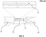
Fig. 4 is a section view ofFig. 1 , and shows the microfluidic device having roughness elements formed on inner wall of the micro flow restrictive element according to an embodiment of the present invention. -
Fig. 4A is partly enlarged view ofFig. 4 , and illustrates a part of the microfluidic device having roughness elements formed on inner wall of the micro flow restrictive element according to an embodiment of the present invention. -
Fig. 5 is a cross-section view of micro flow restrictive element showing the roughness elements formed on inner wall of the micro flow restrictive element according to an embodiment of the present invention. -
Fig. 6 shows view of the roughness elements according to an embodiment of the present invention, formed on inner wall of the micro flow restrictive element. - The present invention discloses a device (1), an integrated system (100) including said device (1), and a method for detecting circulating tumor cells (CTCs) in a biological fluid sample in vitro.
- The device (1) according to the present invention is provided for detecting CTCs in a biological fluid sample, and comprises a microfluidic device (20) and an ultrasonic signal processing system (26). Said microfluidic device (20) comprises an inlet portion (21) for receiving the biological fluid sample into said microfluidic device (20), and an outlet portion (22) for discharging the received biological fluid sample from the microfluidic device (20). Said microfluidic device (20) further houses a micro flow restrictive element (23) extending between the inlet portion (21) and the outlet portion (22). Thereby, as shown in
Figs. 1 ,3 and4 , respectively the inlet portion (21), the micro flow restrictive element (23) and the outlet portion (22) form a fluid passage within said microfluidic device (20) for the biological fluid sample to flow through the micro flow restrictive element (23). The inlet portion (21) of the microfluidic device (20) has an inner cross-section area larger than inner cross-section area of said micro flow restrictive element, which causes a sudden reduction in the inner cross-section area of said fluid passage at the location where the fluid passes from the inlet portion (21) to the micro flow restrictive element (23), i.e., especially to an inlet zone (24) of the micro flow restrictive element (23). This reduction induces pressure of the biological fluid sample flowing through the inlet zone (24) of said micro flow restrictive element (23) to rapidly drop to a critical level, which is equal to or below saturated vapor pressure of said fluid sample at room temperature (about 20 °C). - The rapid drop of pressure of the biological fluid sample to its critical level leads formation of microbubbles (small vapor-filled cavities) in said biological fluid sample while it is flowing through the micro flow restrictive element (23), especially through the inlet zone (24) which is close to the inlet portion (21) where the pressure is relatively low. As will be acknowledged by a skilled person in the art, length of the inlet zone (24) within the micro flow restrictive element (23) can appropriately be calculated, and thus be adjusted especially by considering measured pressure value on the biological fluid sample flowing through said inlet zone (24). Formation of the microbubbles is disclosed by phenomenon called as cavitation inception.
- The ultrasonic signal processing system (26) of the device (1) includes an ultrasonic transmitter (27) for transmitting ultrasound waves on said biological fluid sample while it is flowing through said micro flow restrictive element (23); and an ultrasonic receiver (28) for receiving ultrasound waves reflected from said biological fluid sample. Said ultrasonic signal processing system (26) also comprises an ultrasonic signal processor (29) analyzing information obtained from the ultrasonic transmitter (27) and the ultrasonic receiver (28); and detecting presence of CTCs, if any, in the flowing biological fluid sample considering variation of the monitored reflected ultrasound waves due to generation of cavitation inception based on said rapid pressure drop within the micro flow restrictive element (23).
- The tested biological fluid sample may be a blood or serum sample. Optionally, the tested biological fluid sample may be CTC-enriched blood or serum sample. Furthermore, the biological fluid sample may comprise at least one of white blood cells (WBCs), red blood cells (RBCs), CTCs or any combination thereof.
- Differential response of cavitation inception to micro-level adjustment of environmental conditions (such as liquid pressure) could be used as indicator of altered rheological characteristics. Furthermore, it is known that, rheological characteristics of fluids change when there are solid particles (i.e., cell) floating inside said fluid. In the technique, it is reported that size (diameter, area or volume) of a CTC is considered to be larger than any normal blood cell (WBC, RBC, etc.). As to exemplify, volume of a breast cancer CTC is measured as 851.6 ± 45.8 µm3 , and an Ovarian cancer CTC as 518.3 ± 24.5 µm3 while volume of a RBC is measured as 100.6 ± 4 µm3 , and a WBC as 234.1 ± 4.1 µm3 and Platelet as 10.5 ± 0.5 µm3 by DIC microscope [K. Phillips, A. Kolatkar, K. Rees, R. Rigg, D.Marrinucci,M. Luttgen, K. Bethel, P. Kuhn, O. McCarty, Quantification of cellular volume and sub-cellular density fluctuations: comparison of normal peripheral blood cells and circulating tumor cells identified in a breast cancer patient, Front. Oncol. 2 (2012).]. Area of a breast cancer CTC is measured as 290 ± 200 µm2, a colorectal cancer CTC as 186 ± 153 µm2, a prostate cancer CTC as 180 ± 145 µm2 while area of a WBC is measured as 71 ± 44 µm2 by Images from CellSearch® system [S.T. Ligthart, F.A. Coumans, F.-C. Bidard, L.H. Simkens, C.J. Punt, M.R. de Groot, G. Attard, J.S. de Bono, J.-Y. Pierga, L.W. Terstappen, Circulating tumor cells count and morphological features in breast, colorectal and prostate cancer, PLoS One 8 (2013) e67148.]. Thereby, the rheology of the biological fluid sample without CTCs (i.e., healthy sample) is clearly different from that of the biological fluid sample including CTCs because, as exemplified above, the biological fluid sample including CTCs (unhealthy sample) contains cells of a larger size than the healthy sample. Accordingly, compared to the healthy sample, early cavitation inception is observed for the biological fluid sample including CTCs and supercavitation condition appeared sooner where the supercavitation flow regime corresponds to a fully developed cavitating flow. Furthermore, particles in the biological fluid sample are affecting the cavitation inception behavior considerably, especially if they have surface area that contains nano/micro-level irregularities. With this type of irregular surface area, cavitation inception occurs at lower inlet pressures. CTCs are abnormal cells with irregular surfaces, and any biological fluid sample having CTCs and especially CTC-enriched sample is therefore expected to observe early cavitation inception as compared to healthy sample. Consequently, compared to the healthy sample, cavitation inception and hence the generation of microbubbles is observed earlier in the biological fluid sample containing CTCs; and the generated microbubbles are easily detected by the ultrasonic signal processing system (26) according to the present invention.
- According to a preferred embodiment of the present invention, cross-sectional area of one or more of the inlet portion (21), outlet portion (22), micro flow restrictive element (23) and inlet zone (24) disclosed in the present specification may be rectangular. Accordingly, depth of at least any one of the inlet portion (21), outlet portion (22), micro flow restrictive element (23) and inlet zone (24) may optionally be selected around 50 µm. According to an embodiment, hydraulic diameter of the micro flow restrictive element (W2) is between 10 µm to 250 µm, and preferably between 150 µm to 250 µm. As will be acknowledged by a skilled person, the hydraulic diameter of the micro flow restrictive element (W2) may be designed according to the type of the cancer that is required to be detected with said device (1) and accordingly, an optimization may be beneficial in order to realize a precise measurement, taking into account the size of the CTC to be detected, the inlet pressure of the biological fluid sample fed to the inlet portion (21) of the microfluidic device (20) and the hydraulic diameter of the micro flow restrictive element (W2). According to a preferred embodiment of the present invention, the inlet pressure of the biological fluid sample fed to the inlet portion (21) of the microfluidic device (20) is between 1 to 3 MPa. Optionally, the inlet pressure and outlet pressure of the microfluidic device (20) may be regulated through a programmable pressure controller (not shown). Main velocity of the cavitating flow inside the micro flow restrictive element (23) may optionally be selected/adjusted as to be between 20 to 52 m/s for the inlet pressures of 1 to 3 MPa. Furthermore, the length of the micro flow restrictive element (L2) extending between the inlet portion (21) and the outlet portion (22) is optionally selected between 0.5 mm and 2 mm which can be designed according to the desired outlet pressure of the microfluidic device (20). In
Fig.4 , length of the inlet portion (21) is shown with "L1" and length of the outlet portion (22) is shown with "L3". According to another embodiment, hydraulic diameter of the inlet portion (W1) may be selected around 900 µm. - According to an embodiment of the present invention, the micro flow restrictive element (23) is in structure of a micro orifice optionally having a functional inner surface. Said functional inner surface can be exemplified with roughness elements formed on inner wall (25) surface of said micro flow restrictive element (23). Optionally, said roughness elements are formed on inner wall surface of the inlet zone (24). The roughness elements may be selected from micro/nano pin fins, crevices, cavities, mechanically deformed structures, porous materials, sintered wires/meshes, micro/nano structures and any other complex geometries. Particles in the biological fluid sample affect the cavitation inception behavior considerably, especially if said sample is flowing through a fluid passage with an inner surface area containing any roughness elements. The formed roughness elements lead the biological fluid sample having particles such as CTCs to flow by providing earlier inception of cavitating microbubbles as compared to healthy blood sample and by intensifying developed cavitating flows (supercavitation condition). According to an embodiment of the present invention, height of the roughness elements (HR) can be selected from 0.01W2 to 0.1W2 where the coefficient "W2" corresponds to the hydraulic diameter of the micro flow restrictive element (23). Optionally, length of region designed with said roughness elements (LR) can be selected between 0.3L2 to L2 where the coefficient "L2" corresponds to total length of the micro flow restrictive element (23). In
Fig. 4 , W3 corresponds to the hydraulic diameter of the outlet portion (22). -
Fig. 5 provides a cross-section view of micro flow restrictive element showing the roughness elements formed on inner wall of the micro flow restrictive element according to an embodiment of the present invention. Furthermore,Fig. 6 provides surface morphology of the roughness elements formed on inner wall of the micro flow restrictive element according to an embodiment of the present invention. - Present invention further discloses an integrated system (100) for enriching and detecting circulating tumor cells (CTCs) in a biological fluid sample. The integrated system (100), provided in
Fig.1 , comprises the device (1) as provided in any one of the above disclosed embodiments of the present invention, and a microfluidic enrichment device (10) for enriching the CTCs in said biological fluid sample before feeding the same to the device (1). Said microfluidic enrichment device (10) comprises a micro-channel (11) having at least a channel inlet (12) and at least a channel outlet (13) for said biological fluid sample flow. The microfluidic enrichment device (10) is preferably carries out a process for enrichment of the CTCs in biological fluid sample (if any) as to provide typically 1×10³ to 3×10⁵ CTC cells/mL of the sample. As an embodiment, said microfluidic enrichment device (10) may be any efficient device provided for CTC enrichment. The microchannel may be selected from various types of channel geometries including straight, spiral, serpentine, curvilinear and straight channel with contraction-expansion arrays in inertial microfluidics. Preferably, the microchannel is curvilinear as shown inFigs. 1 and2 . On the other hand, the microfluidic enrichment device (10) may be selected from the categories of active or passive separation depending on its energy usage. Active techniques require external forces such as magnetic, dielectric, and acoustic to separate particles/cells, while passive techniques utilize mainly hydrodynamic forces. - According to an embodiment of the present invention, said integrated system (100) may be designed as a Lab-on-Chip (LOC) Device.
- The present invention further discloses a method for detecting circulating tumor cells (CTCs) in a biological fluid sample, comprising the steps of:
- a. supplying the biological fluid sample to the inlet portion (21) of the microfluidic device (20) housing the micro flow restrictive element (23) where inner cross-section area of the microfluidic device is larger than inner cross-section area of said micro flow restrictive element;
- b. transmitting ultrasound waves on said biological fluid sample while it is flowing through said micro flow restrictive element (23);
- c. receiving ultrasound waves reflected from said biological fluid sample;
- d. analyzing information according to values of the transmitted and received ultrasound waves, where variation of the monitored reflected ultrasound waves indicates generation of cavitation inception due to rapid drop in pressure of the biological fluid sample flowing through inlet zone (24) of said micro flow restrictive element (23), which further indicates presence of CTCs in said biological fluid sample.
- According to an embodiment of the present invention the CTC detection method further comprises a step of performing a CTC enrichment treatment on said biological fluid sample to obtain a CTC-enriched biological fluid sample, before supplying the same to the inlet portion (21) of the microfluidic device (20).
- The analyzing step of the proposed CTC detection method is performed by the ultrasonic signal processing system (26) of the device (1) according to the present invention. Thereby, the CTC detection method may optionally comprise a step regarding to detection of CTCs by real-time monitoring the values of the transmitted and received ultrasound waves during flowing of the biological fluid sample through the micro flow restrictive element (23). As disclosed above, analysing step is realized by considering variation, if any, of the monitored reflected ultrasound waves due to generation of cavitation inception or supercavitation condition based on said rapid pressure drop within the micro flow restrictive element (23).
- The present invention further discloses the use of the device (1) and also the integrated system (100) according to the present invention for in vitro detection of CTCs in a biological fluid sample.
- Reference to "embodiment" throughout this specification means that a particular feature, structure or characteristic described in connection with the embodiment is included in at least one embodiment of the present invention. Thus, throughout this specification, the phrases "in one embodiment" or "in an embodiment" may not necessarily all referring to the same embodiment, but also may. For example, in the following claims, any of the claimed embodiments can be used in any combination.
-
- 1
- device
- 10
- microfluidic enrichment device
- 11
- channel
- 12
- channel inlet
- 13
- channel outlet
- 20
- microfluidic device
- 21
- inlet portion
- 22
- outlet portion
- 23
- micro flow restrictive element
- 24
- inlet zone
- 25
- inner wall
- 26
- ultrasonic signal processing system
- 27
- ultrasonic transmitter
- 28
- ultrasonic receiver
- 29
- ultrasonic signal processor
- 100
- integrated system
- HR
- height of the roughness elements
- LR
- length of region designed with said roughness elements
- L1
- length of the inlet portion
- L2
- length of the micro flow restrictive element
- L3
- length of the outlet portion
- W1
- hydraulic diameter of the inlet portion
- W2
- hydraulic diameter of the micro flow restrictive element
- W2
- hydraulic diameter of the outlet portion
Claims (13)
- A device (1) for detecting circulating tumor cells (CTCs) in a biological fluid sample, comprising- a microfluidic device (20) having an inlet portion (21) for receiving the biological fluid sample into said microfluidic device (20), and an outlet portion (22) for discharging the received biological fluid sample from said microfluidic device (20); characterized in that said microfluidic device (20) further houses a micro flow restrictive element (23) extending between the inlet portion (21) and the outlet portion (22) of said microfluidic device (20); wherein inner cross-section area of the inlet portion of the microfluidic device (20) is larger than inner cross-section area of said micro flow restrictive element; and this reduction in inner cross-section area between the microfluidic device (20) and the micro flow restrictive element (23) configured to induce a rapid drop in pressure of the biological fluid sample flowing through inlet zone (24) of said micro flow restrictive element (23) to a critical level, which is equal to or below saturated vapor pressure of said fluid sample at room temperature;- an ultrasonic signal processing system (26) including:an ultrasonic transmitter (27) configured for transmitting ultrasound waves on said biological fluid sample while it is flowing through said micro flow restrictive element (23);an ultrasonic receiver (28) configured for receiving ultrasound waves reflected from said biological fluid sample; andan ultrasonic signal processor (29) configured for analyzing information obtained from the ultrasonic transmitter (27) and the ultrasonic receiver (28) and configured for detecting presence of CTCs within the flowing biological fluid sample by considering variation of the monitored reflected ultrasound waves due to generation of cavitation inception based on said rapid pressure drop within the micro flow restrictive element (23).
- The device (1) according to claim 1, wherein the biological fluid sample is a CTC-enriched blood or serum sample.
- The device (1) according to claim 1 or 2, wherein the biological fluid sample comprises at least one of white blood cells (WBCs), red blood cells (RBCs), CTCs or any combination thereof.
- The device (1) according to any one of the claims 1 to 3, wherein hydraulic diameter of the micro flow restrictive element (23) is between 10 µm to 250 µm.
- The device (1) according to any one of the claims 1 to 4, comprising roughness elements formed on inner wall (25) surface of said micro flow restrictive element (23).
- The device (1) according to claim 5, wherein height of the roughness elements (HR) is selected from 0.01W2 to 0.1 W2 where the hydraulic diameter of the micro flow restrictive element (23) is 1 W2.
- The device (1) according to claim 5 or 6, wherein the roughness elements are formed on inner wall surface of inlet zone (24) of the micro flow restrictive element (23).
- An integrated system (100) for enriching and detecting circulating tumor cells (CTCs) in a biological fluid sample, comprisinga microfluidic enrichment device (10) configured for enriching the circulating tumor cells (CTCs) in said biological fluid sample comprising a channel (11) having at least a channel inlet (12) and at least a channel outlet (13) for said biological fluid sample flow; andthe device (1) according to any one of the claims 1 to 7.
- A method for detecting circulating tumor cells (CTCs) in a biological fluid sample, characterized by comprising the steps of:a. supplying the biological fluid sample to an inlet portion (21) of microfluidic device (20) housing a micro flow restrictive element (23) extending between said inlet portion (21) and an outlet portion (22) of said microfluidic device (20) where inner cross-section area of the microfluidic device is larger than inner cross-section area of said micro flow restrictive element, and this reduction in inner cross-section area between the microfluidic device (20) and the micro flow restrictive element (23) induces a rapid drop in pressure of the biological fluid sample flowing through the inlet zone (24) of said micro flow restrictive element (23) to a critical level, which is equal to or below saturated vapor pressure of said fluid sample at room temperature;b. transmitting ultrasound waves on said biological fluid sample while flowing through said micro flow restrictive element (23);c. receiving ultrasound waves reflected from said biological fluid sample;d. analyzing information according to values of the transmitted and received ultrasound waves, where variation of the monitored reflected ultrasound waves indicates generation of cavitation inception due to rapid drop in pressure of the biological fluid sample flowing through inlet zone (24) of said micro flow restrictive element (23), which further indicates presence of CTCs in said biological fluid sample.
- A method according to claim 9 further comprising the step of performing a CTC enrichment treatment on said biological fluid sample to obtain a CTC-enriched biological fluid sample, before step (a).
- A method according to claim 9 or 10 wherein the detection of circulating tumor cells (CTCs) are realized by real-time monitoring the values of the transmitted and received ultrasound waves during flowing of the biological fluid sample through the micro flow restrictive element (23).
- Use of a device (1) according to any one of the claim 1-7 for detecting circulating tumor cells (CTCs) in a biological fluid sample.
- Use of an integrated system (100) according to claim 8 for detecting circulating tumor cells (CTCs) in a biological fluid sample.
Applications Claiming Priority (1)
| Application Number | Priority Date | Filing Date | Title |
|---|---|---|---|
| PCT/TR2020/050676 WO2022025836A1 (en) | 2020-07-29 | 2020-07-29 | A device, an integrated system and a method for detecting circulating tumor cells |
Publications (2)
| Publication Number | Publication Date |
|---|---|
| EP4189388A1 EP4189388A1 (en) | 2023-06-07 |
| EP4189388B1 true EP4189388B1 (en) | 2025-01-08 |
Family
ID=72802133
Family Applications (1)
| Application Number | Title | Priority Date | Filing Date |
|---|---|---|---|
| EP20788914.8A Active EP4189388B1 (en) | 2020-07-29 | 2020-07-29 | A device, an integrated system and a method for detecting circulating tumor cells |
Country Status (2)
| Country | Link |
|---|---|
| EP (1) | EP4189388B1 (en) |
| WO (1) | WO2022025836A1 (en) |
Families Citing this family (2)
| Publication number | Priority date | Publication date | Assignee | Title |
|---|---|---|---|---|
| WO2024124740A1 (en) * | 2022-12-13 | 2024-06-20 | 浙江省肿瘤医院 | Circulating tumor cell detection device based on sers technology |
| TR2024005065A1 (en) | 2024-04-27 | 2025-11-21 | Oezogul Beyzanur | LABORATORY PLATFORM ON A CHIP AND METHOD FOR THROMBOLYSIS |
Family Cites Families (5)
| Publication number | Priority date | Publication date | Assignee | Title |
|---|---|---|---|---|
| EP1984030B1 (en) | 2006-01-30 | 2013-05-08 | The Scripps Research Institute | Methods for detection of circulating tumor cells and methods of diagnosis of cancer in a mammalian subject |
| ES2326109B1 (en) * | 2007-12-05 | 2010-06-25 | Consejo Superior De Investigaciones Cientificas | SELECTIVE AND NON INVASIVE SEPARATION AND EXTRACTION MICRODISPOSITIVE OF PARTICLES IN POLIDISPERSE SUSPENSIONS, MANUFACTURING PROCEDURE AND ITS APPLICATIONS. |
| CN103608682B (en) * | 2011-05-05 | 2017-01-18 | 安派科生物医学科技有限公司 | Tumor Cell Detector |
| WO2015103039A1 (en) | 2013-12-30 | 2015-07-09 | The Scripps Research Institute | Circulating tumor cell diagnostics for lung cancer |
| US10556234B2 (en) | 2015-10-06 | 2020-02-11 | Mohammad Abdolahad | Isolation and detection of circulating tumor cells (CTCs) |
-
2020
- 2020-07-29 WO PCT/TR2020/050676 patent/WO2022025836A1/en not_active Ceased
- 2020-07-29 EP EP20788914.8A patent/EP4189388B1/en active Active
Also Published As
| Publication number | Publication date |
|---|---|
| WO2022025836A1 (en) | 2022-02-03 |
| EP4189388A1 (en) | 2023-06-07 |
Similar Documents
| Publication | Publication Date | Title |
|---|---|---|
| Zheng et al. | A comparison of virtual touch tissue quantification and digital rectal examination for discrimination between prostate cancer and benign prostatic hyperplasia | |
| CN102782498A (en) | Method for detecting rare cells with non-rare cells | |
| EP2335075A1 (en) | Methods for the detection of circulating tumor cells | |
| Strohm et al. | Classification of blood cells and tumor cells using label‐free ultrasound and photoacoustics | |
| AU2019226260A1 (en) | Methods and apparatus for enhanced detection of diseases | |
| EP4189388A1 (en) | A device, an integrated system and a method for detecting circulating tumor cells | |
| JP2018077247A (en) | Systems and methods for platelet count with clump adjustment | |
| JP5997160B2 (en) | Multiphase flow system for detecting and separating materials | |
| EP1912556B1 (en) | Blood sampling catheter | |
| US20090030618A1 (en) | System, method and software arrangement for analyzing and correlating molecular profiles associated with anatomical structures | |
| US20030149358A1 (en) | Ultrasonic system for non-invasive early prostate cancer detection | |
| RU2464574C1 (en) | Diagnostic technique for prostate cancer | |
| Ingle et al. | Fine Needle Aspiration Cytology [FNAC] | |
| KR101635510B1 (en) | In-line lab-on-a-chip system for measuring a difference in speed according to slip of red blood cell membrane and there of optical detection system | |
| Peng et al. | Correlation analysis of ultrasound features with ER, PR, HER-2, P53, nuclear proliferation factor Ki-67, TOPIIa, and cytokeratin CK5/6 immunohistochemistry in non-mass infiltrating ductal carcinoma of the breast | |
| Rezagholi et al. | Early-Stage Cancer Biomarker Detection via Intravascular Nanomachines: Modeling and Analysis | |
| WO2014122491A1 (en) | Testing unit for determining the physical characteristics of samples containing liquid components | |
| Woliński et al. | Content of RNA originating from thyroid in washouts from fine-needle and core-needle aspiration biopsy—preliminary study | |
| Potdevin et al. | Zonal analysis of 3D ultrasound Doppler quantitative measures for the discrimination of prostate cancer | |
| Mousapour | Measuring Biomechanical Properties of Cancer Cells Using a High-Throughput Microfluidic Platform and Their Correlation with Surface Rheology and Internal Elasticity | |
| Mustafa et al. | 493 The accuracy of fine-needle biopsies in renal cancer-A histologic and genetic study | |
| CN113604575A (en) | Marker for breast cancer diagnosis and application thereof | |
| Szabó et al. | Dynamic MR imaging as a predictor of prognosis in breast cancer | |
| D'Urso et al. | 495 Renal cancer detection with a new non invasive diagnostic tool (TRIMPROBTM): A scup pilot study | |
| Rioux-Leclrrcq et al. | 496 Combining clinical, pathological and biological variables allows the identification of patients who are at high risk of renal cell carcinoma related death after radical nephrectomy |
Legal Events
| Date | Code | Title | Description |
|---|---|---|---|
| STAA | Information on the status of an ep patent application or granted ep patent |
Free format text: STATUS: UNKNOWN |
|
| STAA | Information on the status of an ep patent application or granted ep patent |
Free format text: STATUS: THE INTERNATIONAL PUBLICATION HAS BEEN MADE |
|
| PUAI | Public reference made under article 153(3) epc to a published international application that has entered the european phase |
Free format text: ORIGINAL CODE: 0009012 |
|
| STAA | Information on the status of an ep patent application or granted ep patent |
Free format text: STATUS: REQUEST FOR EXAMINATION WAS MADE |
|
| 17P | Request for examination filed |
Effective date: 20230228 |
|
| AK | Designated contracting states |
Kind code of ref document: A1 Designated state(s): AL AT BE BG CH CY CZ DE DK EE ES FI FR GB GR HR HU IE IS IT LI LT LU LV MC MK MT NL NO PL PT RO RS SE SI SK SM TR |
|
| DAV | Request for validation of the european patent (deleted) | ||
| DAX | Request for extension of the european patent (deleted) | ||
| GRAP | Despatch of communication of intention to grant a patent |
Free format text: ORIGINAL CODE: EPIDOSNIGR1 |
|
| STAA | Information on the status of an ep patent application or granted ep patent |
Free format text: STATUS: GRANT OF PATENT IS INTENDED |
|
| INTG | Intention to grant announced |
Effective date: 20240909 |
|
| RAP3 | Party data changed (applicant data changed or rights of an application transferred) |
Owner name: PROGIN BILISIM MUEHENDISLIK VE DANISMANLIKHIZMETLERI LTD. STI. Owner name: SABANCI UENIVERSITESI NANOTEKNOLOJI ARASTIRMA VEUYGULAMA MERKEZI SUNUM Owner name: SABANCI UENIVERSITESI |
|
| GRAS | Grant fee paid |
Free format text: ORIGINAL CODE: EPIDOSNIGR3 |
|
| GRAA | (expected) grant |
Free format text: ORIGINAL CODE: 0009210 |
|
| STAA | Information on the status of an ep patent application or granted ep patent |
Free format text: STATUS: THE PATENT HAS BEEN GRANTED |
|
| AK | Designated contracting states |
Kind code of ref document: B1 Designated state(s): AL AT BE BG CH CY CZ DE DK EE ES FI FR GB GR HR HU IE IS IT LI LT LU LV MC MK MT NL NO PL PT RO RS SE SI SK SM TR |
|
| REG | Reference to a national code |
Ref country code: GB Ref legal event code: FG4D |
|
| REG | Reference to a national code |
Ref country code: CH Ref legal event code: EP |
|
| REG | Reference to a national code |
Ref country code: DE Ref legal event code: R096 Ref document number: 602020044562 Country of ref document: DE |
|
| REG | Reference to a national code |
Ref country code: IE Ref legal event code: FG4D |
|
| REG | Reference to a national code |
Ref country code: LT Ref legal event code: MG9D |
|
| REG | Reference to a national code |
Ref country code: NL Ref legal event code: MP Effective date: 20250108 |
|
| REG | Reference to a national code |
Ref country code: AT Ref legal event code: MK05 Ref document number: 1758634 Country of ref document: AT Kind code of ref document: T Effective date: 20250108 |
|
| PG25 | Lapsed in a contracting state [announced via postgrant information from national office to epo] |
Ref country code: NL Free format text: LAPSE BECAUSE OF FAILURE TO SUBMIT A TRANSLATION OF THE DESCRIPTION OR TO PAY THE FEE WITHIN THE PRESCRIBED TIME-LIMIT Effective date: 20250108 |
|
| PG25 | Lapsed in a contracting state [announced via postgrant information from national office to epo] |
Ref country code: RS Free format text: LAPSE BECAUSE OF FAILURE TO SUBMIT A TRANSLATION OF THE DESCRIPTION OR TO PAY THE FEE WITHIN THE PRESCRIBED TIME-LIMIT Effective date: 20250408 |
|
| PG25 | Lapsed in a contracting state [announced via postgrant information from national office to epo] |
Ref country code: FI Free format text: LAPSE BECAUSE OF FAILURE TO SUBMIT A TRANSLATION OF THE DESCRIPTION OR TO PAY THE FEE WITHIN THE PRESCRIBED TIME-LIMIT Effective date: 20250108 |
|
| PG25 | Lapsed in a contracting state [announced via postgrant information from national office to epo] |
Ref country code: PL Free format text: LAPSE BECAUSE OF FAILURE TO SUBMIT A TRANSLATION OF THE DESCRIPTION OR TO PAY THE FEE WITHIN THE PRESCRIBED TIME-LIMIT Effective date: 20250108 |
|
| PG25 | Lapsed in a contracting state [announced via postgrant information from national office to epo] |
Ref country code: ES Free format text: LAPSE BECAUSE OF FAILURE TO SUBMIT A TRANSLATION OF THE DESCRIPTION OR TO PAY THE FEE WITHIN THE PRESCRIBED TIME-LIMIT Effective date: 20250108 |
|
| PG25 | Lapsed in a contracting state [announced via postgrant information from national office to epo] |
Ref country code: NO Free format text: LAPSE BECAUSE OF FAILURE TO SUBMIT A TRANSLATION OF THE DESCRIPTION OR TO PAY THE FEE WITHIN THE PRESCRIBED TIME-LIMIT Effective date: 20250408 Ref country code: IS Free format text: LAPSE BECAUSE OF FAILURE TO SUBMIT A TRANSLATION OF THE DESCRIPTION OR TO PAY THE FEE WITHIN THE PRESCRIBED TIME-LIMIT Effective date: 20250508 |
|
| PG25 | Lapsed in a contracting state [announced via postgrant information from national office to epo] |
Ref country code: HR Free format text: LAPSE BECAUSE OF FAILURE TO SUBMIT A TRANSLATION OF THE DESCRIPTION OR TO PAY THE FEE WITHIN THE PRESCRIBED TIME-LIMIT Effective date: 20250108 |
|
| PG25 | Lapsed in a contracting state [announced via postgrant information from national office to epo] |
Ref country code: PT Free format text: LAPSE BECAUSE OF FAILURE TO SUBMIT A TRANSLATION OF THE DESCRIPTION OR TO PAY THE FEE WITHIN THE PRESCRIBED TIME-LIMIT Effective date: 20250508 Ref country code: LV Free format text: LAPSE BECAUSE OF FAILURE TO SUBMIT A TRANSLATION OF THE DESCRIPTION OR TO PAY THE FEE WITHIN THE PRESCRIBED TIME-LIMIT Effective date: 20250108 |
|
| PG25 | Lapsed in a contracting state [announced via postgrant information from national office to epo] |
Ref country code: BG Free format text: LAPSE BECAUSE OF FAILURE TO SUBMIT A TRANSLATION OF THE DESCRIPTION OR TO PAY THE FEE WITHIN THE PRESCRIBED TIME-LIMIT Effective date: 20250108 Ref country code: GR Free format text: LAPSE BECAUSE OF FAILURE TO SUBMIT A TRANSLATION OF THE DESCRIPTION OR TO PAY THE FEE WITHIN THE PRESCRIBED TIME-LIMIT Effective date: 20250409 |
|
| PG25 | Lapsed in a contracting state [announced via postgrant information from national office to epo] |
Ref country code: AT Free format text: LAPSE BECAUSE OF FAILURE TO SUBMIT A TRANSLATION OF THE DESCRIPTION OR TO PAY THE FEE WITHIN THE PRESCRIBED TIME-LIMIT Effective date: 20250108 |
|
| PG25 | Lapsed in a contracting state [announced via postgrant information from national office to epo] |
Ref country code: SE Free format text: LAPSE BECAUSE OF FAILURE TO SUBMIT A TRANSLATION OF THE DESCRIPTION OR TO PAY THE FEE WITHIN THE PRESCRIBED TIME-LIMIT Effective date: 20250108 |
|
| PG25 | Lapsed in a contracting state [announced via postgrant information from national office to epo] |
Ref country code: SM Free format text: LAPSE BECAUSE OF FAILURE TO SUBMIT A TRANSLATION OF THE DESCRIPTION OR TO PAY THE FEE WITHIN THE PRESCRIBED TIME-LIMIT Effective date: 20250108 |
|
| REG | Reference to a national code |
Ref country code: DE Ref legal event code: R097 Ref document number: 602020044562 Country of ref document: DE |
|
| PG25 | Lapsed in a contracting state [announced via postgrant information from national office to epo] |
Ref country code: DK Free format text: LAPSE BECAUSE OF FAILURE TO SUBMIT A TRANSLATION OF THE DESCRIPTION OR TO PAY THE FEE WITHIN THE PRESCRIBED TIME-LIMIT Effective date: 20250108 |
|
| PGFP | Annual fee paid to national office [announced via postgrant information from national office to epo] |
Ref country code: DE Payment date: 20250812 Year of fee payment: 6 |
|
| PGFP | Annual fee paid to national office [announced via postgrant information from national office to epo] |
Ref country code: TR Payment date: 20250729 Year of fee payment: 6 |
|
| PGFP | Annual fee paid to national office [announced via postgrant information from national office to epo] |
Ref country code: GB Payment date: 20250826 Year of fee payment: 6 |
|
| PG25 | Lapsed in a contracting state [announced via postgrant information from national office to epo] |
Ref country code: EE Free format text: LAPSE BECAUSE OF FAILURE TO SUBMIT A TRANSLATION OF THE DESCRIPTION OR TO PAY THE FEE WITHIN THE PRESCRIBED TIME-LIMIT Effective date: 20250108 Ref country code: CZ Free format text: LAPSE BECAUSE OF FAILURE TO SUBMIT A TRANSLATION OF THE DESCRIPTION OR TO PAY THE FEE WITHIN THE PRESCRIBED TIME-LIMIT Effective date: 20250108 |
|
| PG25 | Lapsed in a contracting state [announced via postgrant information from national office to epo] |
Ref country code: RO Free format text: LAPSE BECAUSE OF FAILURE TO SUBMIT A TRANSLATION OF THE DESCRIPTION OR TO PAY THE FEE WITHIN THE PRESCRIBED TIME-LIMIT Effective date: 20250108 |
|
| PG25 | Lapsed in a contracting state [announced via postgrant information from national office to epo] |
Ref country code: SK Free format text: LAPSE BECAUSE OF FAILURE TO SUBMIT A TRANSLATION OF THE DESCRIPTION OR TO PAY THE FEE WITHIN THE PRESCRIBED TIME-LIMIT Effective date: 20250108 |
|
| PLBE | No opposition filed within time limit |
Free format text: ORIGINAL CODE: 0009261 |
|
| STAA | Information on the status of an ep patent application or granted ep patent |
Free format text: STATUS: NO OPPOSITION FILED WITHIN TIME LIMIT |
|
| REG | Reference to a national code |
Ref country code: CH Ref legal event code: L10 Free format text: ST27 STATUS EVENT CODE: U-0-0-L10-L00 (AS PROVIDED BY THE NATIONAL OFFICE) Effective date: 20251119 |
|
| 26N | No opposition filed |
Effective date: 20251009 |
|
| PG25 | Lapsed in a contracting state [announced via postgrant information from national office to epo] |
Ref country code: IT Free format text: LAPSE BECAUSE OF FAILURE TO SUBMIT A TRANSLATION OF THE DESCRIPTION OR TO PAY THE FEE WITHIN THE PRESCRIBED TIME-LIMIT Effective date: 20250108 |
|
| REG | Reference to a national code |
Ref country code: CH Ref legal event code: H13 Free format text: ST27 STATUS EVENT CODE: U-0-0-H10-H13 (AS PROVIDED BY THE NATIONAL OFFICE) Effective date: 20260224 |
|
| PG25 | Lapsed in a contracting state [announced via postgrant information from national office to epo] |
Ref country code: LU Free format text: LAPSE BECAUSE OF NON-PAYMENT OF DUE FEES Effective date: 20250729 |
|
| REG | Reference to a national code |
Ref country code: BE Ref legal event code: MM Effective date: 20250731 |
|
| PG25 | Lapsed in a contracting state [announced via postgrant information from national office to epo] |
Ref country code: BE Free format text: LAPSE BECAUSE OF NON-PAYMENT OF DUE FEES Effective date: 20250731 |
|
| PG25 | Lapsed in a contracting state [announced via postgrant information from national office to epo] |
Ref country code: FR Free format text: LAPSE BECAUSE OF NON-PAYMENT OF DUE FEES Effective date: 20250731 |
|
| PG25 | Lapsed in a contracting state [announced via postgrant information from national office to epo] |
Ref country code: CH Free format text: LAPSE BECAUSE OF NON-PAYMENT OF DUE FEES Effective date: 20250731 |