EP4188812B1 - Rolling apparatus for advancing liquid through tubing - Google Patents
Rolling apparatus for advancing liquid through tubing Download PDFInfo
- Publication number
- EP4188812B1 EP4188812B1 EP21755321.3A EP21755321A EP4188812B1 EP 4188812 B1 EP4188812 B1 EP 4188812B1 EP 21755321 A EP21755321 A EP 21755321A EP 4188812 B1 EP4188812 B1 EP 4188812B1
- Authority
- EP
- European Patent Office
- Prior art keywords
- tubing
- roller
- liquid material
- length
- unit
- Prior art date
- Legal status (The legal status is an assumption and is not a legal conclusion. Google has not performed a legal analysis and makes no representation as to the accuracy of the status listed.)
- Active
Links
Images




Classifications
-
- B—PERFORMING OPERATIONS; TRANSPORTING
- B65—CONVEYING; PACKING; STORING; HANDLING THIN OR FILAMENTARY MATERIAL
- B65B—MACHINES, APPARATUS OR DEVICES FOR, OR METHODS OF, PACKAGING ARTICLES OR MATERIALS; UNPACKING
- B65B69/00—Unpacking of articles or materials, not otherwise provided for
- B65B69/005—Unpacking of articles or materials, not otherwise provided for by expelling contents, e.g. by squeezing the container
-
- F—MECHANICAL ENGINEERING; LIGHTING; HEATING; WEAPONS; BLASTING
- F04—POSITIVE - DISPLACEMENT MACHINES FOR LIQUIDS; PUMPS FOR LIQUIDS OR ELASTIC FLUIDS
- F04B—POSITIVE-DISPLACEMENT MACHINES FOR LIQUIDS; PUMPS
- F04B43/00—Machines, pumps, or pumping installations having flexible working members
- F04B43/08—Machines, pumps, or pumping installations having flexible working members having tubular flexible members
-
- F—MECHANICAL ENGINEERING; LIGHTING; HEATING; WEAPONS; BLASTING
- F04—POSITIVE - DISPLACEMENT MACHINES FOR LIQUIDS; PUMPS FOR LIQUIDS OR ELASTIC FLUIDS
- F04B—POSITIVE-DISPLACEMENT MACHINES FOR LIQUIDS; PUMPS
- F04B43/00—Machines, pumps, or pumping installations having flexible working members
- F04B43/12—Machines, pumps, or pumping installations having flexible working members having peristaltic action
- F04B43/1223—Machines, pumps, or pumping installations having flexible working members having peristaltic action the actuating elements, e.g. rollers, moving in a straight line during squeezing
-
- F—MECHANICAL ENGINEERING; LIGHTING; HEATING; WEAPONS; BLASTING
- F16—ENGINEERING ELEMENTS AND UNITS; GENERAL MEASURES FOR PRODUCING AND MAINTAINING EFFECTIVE FUNCTIONING OF MACHINES OR INSTALLATIONS; THERMAL INSULATION IN GENERAL
- F16K—VALVES; TAPS; COCKS; ACTUATING-FLOATS; DEVICES FOR VENTING OR AERATING
- F16K7/00—Diaphragm valves or cut-off apparatus, e.g. with a member deformed, but not moved bodily, to close the passage ; Pinch valves
- F16K7/02—Diaphragm valves or cut-off apparatus, e.g. with a member deformed, but not moved bodily, to close the passage ; Pinch valves with tubular diaphragm
- F16K7/04—Diaphragm valves or cut-off apparatus, e.g. with a member deformed, but not moved bodily, to close the passage ; Pinch valves with tubular diaphragm constrictable by external radial force
- F16K7/06—Diaphragm valves or cut-off apparatus, e.g. with a member deformed, but not moved bodily, to close the passage ; Pinch valves with tubular diaphragm constrictable by external radial force by means of a screw-spindle, cam, or other mechanical means
- F16K7/061—Screw clamps
Definitions
- liquids e.g. , drug materials
- the loss of reaction efficiency, or of final drug product, can have negative financial impacts as well.
- US 2009/320879 A1 discloses an apparatus for clearing tubing including a gripp assembly connected to a pair of rollers.
- US 1 699 993 A1 relates to improvements in tube cleaners and more particularly to a device for use by undertakers and surgeons.
- US 2006/081647 A1 describes a device for stripping fluid from a tube.
- the apparatus includes a first arm, including a first longitudinal member extending between a first hinged end and a first movable end. A first opening is defined by interior sidewalls of the first longitudinal member, the first hinged end, and the first movable end.
- the apparatus further includes a first roller disposed within the first opening, the first roller rotatable around a first axis extending longitudinally between the interior sidewall of the first hinged end and the interior sidewall of the first movable end.
- the apparatus further includes a second arm including a second longitudinal member extending between a second hinged end and a second movable end.
- a second opening is defined by interior sidewalls of the second longitudinal member, the second hinged end, and the second movable end.
- the apparatus further includes a second roller disposed within the second opening, the second roller rotatable around a second axis extending longitudinally between the interior sidewall of the second hinged end and the interior sidewall of the second movable end.
- the apparatus optionally includes an advancing unit coupled to the first roller and configured to rotate the first roller around the first axis.
- the first arm may be coupled to the second arm via a hinged coupling between the first hinged end and the second hinged end. The hinged coupling provides for the first movable end and the second movable end to move in relation to one another.
- a space is defined between the first roller and the second roller.
- a system in another, interrelated aspect, includes a flexible tubing and a rolling apparatus coupled to the tubing.
- the rolling apparatus is the same as, or substantially similar to, the apparatus described above such that its features and functions will not be repeated here for the sake of brevity.
- the tubing is positioned in a space defined between the first roller and the second roller.
- the system includes a transfer unit.
- the system further includes a length of tubing having a first end and a second end, the first end coupled to the transfer unit such that a liquid (e.g., drug material) can move from the transfer unit into the length of tubing and can exit the tubing.
- the system further includes a liquid material removal apparatus releasably coupled to the length of tubing. The apparatus can compress the tubing sufficiently to seal the tubing, and the apparatus can be configured to move along the length of tubing in order to move the liquid material along the length of tubing.
- the first movable end and the second movable end can be movable relative to one another to form a closed position in which the first roller and the second roller are substantially parallel to one another. In the closed position, a first end region of the first movable end can abut a second end region of the second movable end.
- the space between the first roller and the second roller can accommodate a piece of tubing such that, when the apparatus is closed with a piece of tubing inserted between the first and second rollers, the piece of tubing can be compressed in the space between the first roller and the second roller.
- the space between the first roller and the second roller can be such that when a tubing is compressed therebetween, the rollers can move relative to the piece of tubing.
- the movement can be provided by sliding the apparatus over the piece of tubing.
- the movement can be provided by manually sliding the apparatus over the piece of tubing.
- the movement can be provided by an advancing unit, and the advancing unit can be rotated to rotate the first roller.
- the advancing unit can include a crank.
- the apparatus includes a securing unit.
- the securing unit includes a first securing component coupled to the first movable end of the first arm and a second securing component coupled to the second movable end of the second arm, the first securing component and the second securing component configured to engage one another to secure together the first movable end and the second movable end.
- One or both of the first roller and the second roller can include one of a smooth outer surface, a textured outer surface, or a serrated outer surface.
- the rolling apparatus can further include an advancing unit coupled to the first roller and configured to rotate the first roller around the first axis.
- the movement of the rollers relative to the tubing can advance liquid in the tubing along the tubing.
- the system can further include a receiving unit, such that the tubing can be coupled on the second end to the receiving unit, and the liquid material can move from the transfer unit to the receiving unit through the length of tubing.
- the rolling apparatus can further include an adjustment mechanism.
- the adjustment mechanism can be present on one or both of the first roller and/or the second roller.
- the adjustment mechanism can be configured to modulate the space between the first roller and the second roller such that sufficient pressure is provided to seal the piece of tubing therebetween.
- the adjustment mechanism can be a pressure regulating mechanism.
- the pressure regulating mechanism can be any one of a screw mechanism, a plurality of notches, and a spring mechanism.
- the liquid or liquid material can include a drug material.
- the liquid or liquid material can include a cell culture medium, spent medium, cell culture supplement, cell culture additive, cell culture feed, a buffer, or water.
- the drug material can include a pharmaceutical compound or a precursor to a pharmaceutical compound.
- the pharmaceutical compound can be a biologic.
- the biologic can be selected from a peptide, a protein, a vaccine, a nucleic acid, a virion, and a cell.
- the protein can be an antibody or fragment thereof, an antigen, a cytokine, an enzyme, a hormone, a recombinant protein, or a fusion protein.
- the manufacturing of many therapeutic products is a difficult and expensive process. That is particularly true for a number of therapeutics manufactured using biotechnology.
- the failure to collect even small amounts of liquid material can result in the loss of not only important drug supply, but in a major economic loss.
- some liquid manufacturing processes require the movement of liquid material through tubing, for example, in order to transfer liquid material from one receptacle to another location. It can be difficult to remove all such liquid material from such tubing.
- the instant technology relates generally to systems, devices, and methods for collecting liquid substance, in some cases very small quantities, that otherwise might go uncollected during the manufacturing process.
- a rolling apparatus that can be used in pharmaceutical manufacturing or other applications requiring the elimination of a liquid material from a flexible tube.
- the rolling apparatus is configured to advance a liquid through flexible tubing by compressing the tubing as the rolling apparatus moves along the tubing from a first end toward a second end.
- a manufacturing or synthesis system can include a first receptacle and a second receptacle, and a length of tubing connecting the first receptacle to the second receptacle.
- the rolling apparatus can be secured around the tubing at (near) the first receptacle, and advanced along the length of the tubing, compressing the tubing as it moves along the length of the tubing and forcing liquid material along the length of the tubing from the first receptacle into the second receptacle, thereby eliminating any residual liquid material in the tubing.
- Various embodiments of the rolling apparatus, and related systems and methods, are described in detail below.
- FIGS. 1A-1E illustrate a first embodiment of a rolling apparatus 100.
- the rolling apparatus 100 includes a top arm 110a and a bottom arm 110b, connected at a hinge 140.
- the top arm 110a includes a longitudinal member extending between a first end connected to the hinge 140 and a second, moveable end.
- the top arm 110a also includes a top roller 120a disposed within an opening defined by the interior sidewalls of the top arm 110a.
- the top roller 120a is configured to rotate around a first axis that extends longitudinally from the end of the top arm 110a connected to the hinge 140 to the moveable end of the top arm 110a.
- the top roller 120a can also include an advancing unit 130.
- the advancing unit 130 can be coupled to the top roller 120a and can rotate the top roller 120a around the first axis.
- the advancing unit 130 can be, for example, a finger crank, a knob, a switch, a ratchet, a sliding mechanism, a drill connection, or the like.
- the bottom arm 110b comprises a second longitudinal member extending between a first end connected to the hinge 140 and a second, moveable end.
- the hinge 140 can be configured to provide a coupling between the top arm 110a and the bottom arm 110b such that the moveable ends of the top arm 110a and the bottom arm 110b can move in relation to one another, for example swinging between a closed position and an open position.
- the top arm 110a can abut the bottom arm 120b.
- the bottom arm 110b includes a bottom roller 120b disposed within an opening defined by the interior sidewalls of the bottom arm 110b.
- the bottom roller 120b is configured to rotate around a second axis, extending longitudinally from the end of the bottom arm 110b attached to the hinge 140 to the moveable end of the bottom arm 110b.
- the top roller 120a can be substantially parallel to the bottom roller 120b, and a space 150 can be formed between the top roller 120a and the bottom roller 120b.
- the size of the space 150 is correlated to the size and thickness of the tubing that will be used with the rolling apparatus 100.
- the space 150 can be configured to accommodate a piece of tube or tubing.
- the dimensions of the space 150 can be modified by either shifting the first axis and/or the second axis up or down, or by increasing or decreasing the diameter of the top roller 120a and/or the bottom roller 120b. Additionally and/or alternatively, the dimensions of the space 150 can be modified by increasing or decreasing the length and/or height of the top arm 110a and the bottom arm 110b.
- the tube or tubing can have an inner diameter and an outer diameter, the inner diameter defining an inner lumen. In some embodiments, the tubing can have an inner diameter of approximately 0.5 inches, and an outer diameter of approximately 0.75 inches. It should be appreciated that the size of the tubing may vary without departing from the scope of this disclosure.
- FIG. 1B illustrates a top view of the rolling apparatus 100.
- the top arm 110a and the advancing unit 130 are shown.
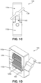
- FIG. 1C illustrates a side view of the rolling apparatus 100. As can be seen in FIG. 1C , the advancing unit 130 can be located on the same side of the rolling apparatus 100 as the hinge 140.
- FIG. 1D illustrates a front perspective view of the rolling apparatus 100
- FIG. 1E illustrates a rear perspective view.
- the top arm 110a with top roller 120a, bottom arm 110b with bottom roller 120b, hinge 140, and advancing unit 130 are illustrated.
- FIGS. 2A-2D illustrate various components of the rolling apparatus 100.
- FIG. 2A shows the top arm 110a.
- the top arm 110a can include a recess 240a.
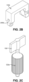
- FIG. 2B shows the bottom arm 110b. which can include a protrusion 240b.
- the recess 240a shown in FIG. 2A can be configured to receive the protrusion 240b and thereby form the hinge 140.
- FIG. 2C shows the advancing unit 130 coupled to the top roller 120a.
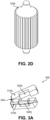
- FIG. 2D illustrates, in a perspective view, the bottom roller 120b.
- FIG. 3A illustrates another embodiment of a rolling apparatus 300.
- the rolling apparatus 300 includes a top arm 310a, a top roller 320a, a bottom arm 310b, a bottom roller 320b, and a hinge 340 which are the same as, or substantially similar to, those described above such that their features and functions will not be repeated here for the sake of brevity.
- the rolling apparatus 300 is shown in an open configuration. In some embodiments, the rolling apparatus 300 can be moved along a length of tubing, by sliding the rolling apparatus 300 over the piece of tube or tubing.
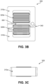
- FIG. 3B illustrates another embodiment of a rolling apparatus 300 similar to FIG. 3A .
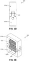
- FIGs. 3C-3E provide different views of the rolling apparatus 300 of FIG. 3B .
- FIGS. 4A-4B illustrate an embodiment of a tube rolling system 400.
- the tube rolling system includes a top arm 410a, a bottom arm 410b, a bottom roller 420b, a hinge 440, and an advancing unit 430 which are the same as, or substantially similar to, those described above such that their features and functions will not be repeated here for the sake of brevity.
- FIG. 4A shows the tube rolling system 400 in an open position.
- the tube rolling system 400 can also include a securing unit having a first securing component 460a and a second securing component 460b.
- first securing component 460a can be coupled to the moveable end of the top arm 410a
- second securing component 460b can be coupled to the moveable end of the bottom arm 410b, such that the first securing component 460a and the second securing component 460b engage one another to secure together the moveable ends of the top arm 410a and the bottom arm 410b.
- the securing unit can be any suitable fastener, such as a tie, a latch, a releasable adhesive, a snap, a button, or the like.
- FIG. 4B shows the tube rolling system 400 in a closed position around a section of tubing 480.
- the tubing 480 can be positioned in a space 450 defined between the top roller 420a and the bottom roller 420b.
- the tubing 480 can be compressed within the space 450.
- the compression of the tubing 480 within the space 450 can allow movement of the top roller 420a and the bottom roller 420b, relative to the tubing 480.
- the movement can be provided by the advancing unit 430.
- the top roller 420a and the bottom roller 420b can have surfaces configured to assist with gripping and compressing the tubing 480.
- the top arm 410a and the bottom arm 410b may be connected at one or both ends by a fastening means other than a hinge 440.
- the top arm 410a and the bottom arm 410b may be present as separate pieces. The separate pieces may be joined together at one or both ends after insertion of a tube or tubing 480 between the rollers of each arm, for example by a hinge 440 or a securing unit as described above, or by any other suitable fastening means such as a latch, a snap, a button, a hook and eye, a releasable adhesive, a magnetic connection, a friction fit, or the like.
- the top arm 410a and the bottom arm 410b may be connected at both ends prior to insertion of a tube or tubing 480 between the top roller 420a and the bottom roller 420b.
- the top arm 410a and bottom arm 410b may be permanently connected at one or both ends (e.g., the top arm 410a and bottom arm 410b may be a single piece or joined by a fastening mechanism, glue, or the like) or may be releasably connected.
- the top arm 410a and the bottom arm 410b may be a single piece, and the tube rolling system 400 may be configured such that a user inserts the tubing 480 into the space 450 between the top roller 420a and the bottom roller 420b, and pushes (e.g., manually pushes) the tubing 480 through the space 450.
- a user inserts the tubing 480 into the space 450 between the top roller 420a and the bottom roller 420b, and pushes (e.g., manually pushes) the tubing 480 through the space 450.
- rollers shown in FIGs. 1A-1E , 2C and 2D each have a serrated outer surface.
- rollers in any embodiments shown or described herein may have a smooth outer surface.
- rollers in FIG. 3 have a smooth surface, rollers in any embodiments shown or described herein may have a serrated, textured, or grooved outer surface.
- FIGS. 5A-5C the surface texture of one or both of the roller components can be varied.
- FIG. 5A shows a roller 520a having a smooth surface texture.
- FIG. 5B shows a roller 520b having a serrated surface texture.
- FIG. 5C shows a roller 520c having a grooved surface texture.
- the serrations or grooves can assist with gripping of the tubing 480 as it is compressed within the space 450 of the tube rolling system 400.
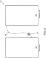
- FIG. 6 is a schematic representation of a production system 605.
- the production system 605 can include a transfer unit, such as a source tank 601, and a receiving unit, such as a receiving tank 602.
- the production system 605 can further include a length of tube 680 coupled to the source tank 601 at a first end of the tube 680 and the receiving tank 602 at a second end of the tube 680.
- the production system 600 can also include a liquid material removal apparatus such as a rolling apparatus 600.
- the rolling apparatus 600 can be releasably coupled to the tube 680 at a point near the source tank 601.
- the rolling apparatus 600 can compress the tube 680, for example the rolling apparatus 600 can provide sufficient compression to seal the tube 680.
- Sealing refers to compressing the tube 680 such that an internal lumen of the tube 680 is collapsed or closed.
- the tube 680 may be sealed by compressing the tube 680 such that two opposed, interior points on the internal lumen contact one another, thereby collapsing at least a portion of the internal lumen of the tube 680.
- the rolling apparatus 600 can be configured to move along a length of the tube 680, and thereby move the liquid material from the source tank 601 to the receiving tank 602.
- a single rolling apparatus can be used with a wide range of tubing having a variety of dimensions. To achieve this, the distance between the roller components of the single rolling apparatus can be adjustable. Described below are various embodiments of bottom roller components of a single rolling apparatus for use with varying tube sizes.
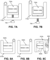
- FIGS. 7A-7B illustrate an embodiment of a bottom arm 710b of a rolling apparatus.
- the rolling apparatus can include an adjustment mechanism, such as a screw mechanism 790.
- the adjustment mechanism can be any positioning or pressure regulating mechanism capable of adjusting the height of the bottom roller 720b within the bottom arm 710b of the rolling apparatus while still providing sufficient support to seal the tube.
- the adjustment mechanisms described herein can be present on one or both of the top arm (not shown) and the bottom arm 710b of a rolling apparatus as described herein including embodiments.
- the screw mechanism 790 can be configured to raise and lower the bottom roller 720b within the bottom arm 710b.
- FIG. 7A shows the screw mechanism 790 having raised the bottom roller 720b.
- FIG. 7B shows the screw mechanism 790 having lowered the bottom roller 720b.
- FIGS. 8A-8C illustrate another embodiment of a bottom arm 810b of a rolling apparatus including an adjustment mechanism to reposition the bottom roller 820b.
- the adjustment mechanism can be notches 890 configured to receive the ends of the bottom roller 820b.
- the bottom roller 820b can be positioned within one of the notches 890 to adjust the height of the bottom roller 820b within the bottom arm 810b.
- FIG. 8A shows the bottom roller 820b positioned within the highest of the notches 890.
- FIG. 8B shows the bottom roller 820b positioned within the lowest of the notches 890.
- FIG. 8C shows the bottom roller positioned within the middle notch of the notches 890.
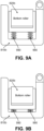
- FIGS. 9A-9B illustrate another embodiment of a bottom arm 910b of a rolling apparatus including an adjustment mechanism.
- the adjustment mechanism can be a pressure regulation mechanism, such as a spring mechanism 990.
- the spring mechanism 990 can be configured to raise or lower the bottom roller 820b while still providing sufficient support to seal the tubing.
- FIG. 9A shows the spring mechanism 990 having raised the bottom roller 820b.
- FIG. 9B shows the spring mechanism having lowered the bottom roller 820b.
- the liquid or liquid material is a drug material, cell culture medium, spent medium, cell culture supplement, cell culture additive, cell culture feed, buffer, concentrated material, or any liquid containing a valuable substance.
- the liquid material can be a drug material.
- the drug material can include a pharmaceutical compound or a precursor to a pharmaceutical compound.
- the pharmaceutical compound can be a biologic.
- the biologic can be one or more of a peptide, a protein, a vaccine, a nucleic acid, a virion, a cell, or a combination thereof.
- the peptide or protein can be an antibody or fragment thereof, an antigen, a cytokine, an enzyme, a hormone, a recombinant protein, or a fusion protein.
- the transfer unit may be, for example, a bioreactor, a filtration unit, a centrifuge unit (e.g., a tube, vessel, basket, holder, cup holder, and the like), a vessel, or a tubing assembly.
- the receiving unit may be, for example, a bioreactor, a filtration unit, a centrifuge unit (e.g., a tube, vessel, basket, holder, cup holder, and the like), a vessel, or a tubing assembly.
- the space between the first roller and the second roller can be any size that accepts a compressed piece of tubing.
- the tubing may be any flexible tubing (e.g., plastic tubing, silicone tubing, latex tubing, etc.).
- the tubing may be of a standard thickness or diameter.
- the tubing may be reinforced or not reinforced.
- the space between the first roller and the second roller can be between about 0.5 millimeters (mm) and about 15 mm.
- the space between the first roller and the second roller can be between about 0.5 mm and about 10 mm.
- the space between the first roller and the second roller can be between about 0.5 mm and about 5 mm.
- the space between the first roller and the second roller can be between about 0.5 mm and about 4 mm.
- the space between the first roller and the second roller can be between about 6 mm and about 15 mm.
- the space between the first roller and the second roller can be between about 7 mm and about 15 mm.
- the space between the first roller and the second roller can be between about 8 mm and about 15 mm.
- the space between the first roller and the second roller can be between about 9 mm and about 15 mm.
- the space between the first roller and the second roller can be between about 10 mm and about 15 mm.
- the space between the first roller and the second roller can be between about 11 mm and about 15 mm.
- the space between the first roller and the second roller can be between about 12 mm and about 15 mm.
- the space between the first roller and the second roller can be between about 13 mm and about 15 mm.
- the space between the first roller and the second roller can be between about 14 mm and about 15 mm.
- the space between the first roller and the second roller can be between about 1 mm and about 10 mm.
- the space between the first roller and the second roller can be between about 1 mm and about 5 mm.
- the space between the first roller and the second roller can be between about 5 mm and about 15 mm.
- the space between the first roller and the second roller can be between about 5 mm and about 10 mm.
- the space can be any value or subrange within the recited ranges, including endpoints.
- the space between the first roller and the second roller can be about 0.5 mm, about 1 mm, about 2 mm, about 3 mm, about 4 mm, about 5 mm, about 6 mm, about 7 mm, about 8 mm, about 9 mm, about 10 mm, about 11 mm, about 12 mm, about 13 mm, about 14 mm, about 15 mm.
- the tubing or length of tubing is open at both ends.
- the tubing can be open on both ends and have one or both ends attached to and/or in fluid contact with a receptacle or reservoir, such as a transfer unit as described herein.
- the tubing or length of tubing is not closed on one end. In embodiments, the tubing or length of tubing is not sealed on one end.
- a method in an aspect, includes coupling a rolling apparatus to tubing.
- the tubing can extend between a transfer unit and a receiving unit.
- the tubing can connect to the interior of the transfer unit at a first end of the tubing, and to the interior of the receiving unit at a second end of the tubing opposite the first end, such that a fluid can move between the transfer unit and the receiving unit along a length of an interior lumen of the tubing.
- the rolling apparatus is the same as, or substantially similar to, the apparatus described above such that its features and functions will not be repeated here for the sake of brevity.
- the tubing is positioned in a space defined between the first roller and the second roller.
- the method further includes advancing the rolling apparatus from a first portion of the tubing to a second portion of the tubing such that liquid in the tubing is advanced from the first portion of the tubing to the second portion of the tubing.
- a method of removing liquid material e.g., a drug material, a concentrated material, a medium or spent medium, a buffer, or any liquid containing a valuable substance
- the method includes providing a transfer unit including a liquid material; providing a receiving unit into which the liquid material is to be transferred; and providing a length of tubing coupled on a first end to the transfer unit and on a second end to the receiving unit.
- the method further includes transferring the liquid material from the transfer unit to the receiving unit via the length of tubing.
- the method further includes releasably coupling a liquid material removal apparatus to the length of tubing at or near the first end, and compressing a subsection of the tubing with the liquid material movement apparatus, thereby sealing the subsection of tubing such that substantially no liquid material can pass through the sealed subsection.
- the method further includes moving the liquid material removal apparatus along the length of tubing toward the receiving unit such that a quantity of liquid material in the length of tubing is moved toward the second end of the length of tubing.
- the method further includes collecting the moved liquid material in the receiving unit.
- the method can include advancing the rolling apparatus from the second portion of the tubing to an entry point of the receiving unit such that the liquid in the tubing can be advanced from the second portion of the tubing to the receiving unit.
- the tubing can be connected to a transfer unit and/or a receiving unit, wherein one or more of the transfer unit and the receiving unit include a bioreactor, a filtration unit, a centrifuge unit (e.g., a tube, vessel, basket, holder, cup holder, and the like), a vessel, or a tubing assembly.
- Coupling the rolling apparatus to the tubing can include positioning the tubing in the space between the first roller and the second roller and moving one or more of the first movable end and the second movable end to form a closed position in which the first roller and the second roller can be substantially parallel to one another.
- all or substantially all of the liquid in the tubing is removed by advancing the rolling apparatus.
- substantially all as used herein means that at least about 70%, about 75%, about 80%, about 85%, about 90%, about 95%, about 99%, or about 99.9% of the liquid that was in the tube prior to advancing the apparatus along the tube is removed from the tube.
- at least about 90% of the liquid that was in the tube prior to advancing the apparatus along the tube is removed from the tube.
- at least about 95% of the liquid that was in the tube prior to advancing the apparatus along the tube is removed from the tube.
- at least about 99% of the liquid that was in the tube prior to advancing the apparatus along the tube is removed from the tube.
- at least about 99.9% of the liquid that was in the tube prior to advancing the apparatus along the tube is removed from the tube.
- the value may be any value or subrange within the recited ranges, including endpoints.
- the liquid material can be a drug material.
- the drug material can include a pharmaceutical compound or a precursor to a pharmaceutical compound.
- the pharmaceutical compound can be a biologic.
- the biologic can be one or more of a peptide, a protein, a vaccine, a nucleic acid, a virion, a cell, or a combination thereof.
- the peptide or protein can be an antibody or fragment thereof, an antigen, a cytokine, an enzyme, a hormone, a recombinant protein, or a fusion protein.
- the precursor to a pharmaceutical compound may be any intermediate in the production of the pharmaceutical compound.
- the precursor may be an intermediate compound, a partially formed peptide, an unfolded/misfolded peptide, media or buffer containing the pharmaceutical compound (or precursor), cells containing the pharmaceutical compound (or precursor), etc.
- a hinge can allow two objects, or two pieces of an object or system, to swing between an open and a closed position.
- the hinge or hinged region can include, without limitation, a latch, a hook and eye, a spring hinge, a barrel hinge, a continuous hinge, a friction hinge, a flush hinge, a double action hinge, a spring hinge, or the like.
- the term "serrated outer surface” is used to refer to any gripping surface, or surface capable of gripping another surface, having serration that aids in the gripping.
- the serration can include, without limitation, teeth, dots, ridges, bumps, detents, protrusions, a combination thereof, or any other suitable configuration capable of aiding in the gripping of another surface.
- textured outer surface is used to refer to any gripping surface, or surface capable of gripping another surface, having a texture that aids in the gripping.
- the texture can include, without limitation, hatching, scoring, etching, laser etching, engraving, a combination thereof, or any other suitable texture capable of aiding in the gripping of another surface.
- smooth outer surface is used to refer to any gripping surface, or surface capable of gripping another surface, having a surface that lacks any serration or texture to aid in the gripping.
- the term "advancing unit" is used to refer to any physical mechanism capable of being manipulated by a user to cause movement, such as rotation of a roller around an axis.
- the advancing unit can include, without limitation, a finger crank, a knob, a drill connection, a switch, a sliding mechanism, a ratcheting mechanism, or any other mechanism suitable for such manipulation by a user to cause rotation of a roller around an axis.
- sliding is used to refer to manual sliding, automated sliding, motorized sliding, remote-controlled sliding, actuated sliding, or any other means by which an object is moved or slid along a length of another object or a medium.
- the terms “tube” or “tubing” are used to refer to an elongate material having an outer diameter and an inner diameter, the inner diameter defining a lumen extending the length of the elongate material.
- the tube may comprise a flexible material, such as a polymer, a plastic, an alloy, a silicone material, or the like.
- liquid or “liquid material” are used to refer to fluid substances exhibiting various viscosities, including inviscid fluids, or fluid substances that include some level of non-liquid material such as biomaterial.
- liquid material may include fluids, fluid-like substances, mixtures of liquid and solid material exhibiting fluid characteristics, inviscid fluids, or the like.
- amino acid refers to naturally occurring and synthetic amino acids, as well as amino acid analogs and amino acid mimetics that function in a manner similar to the naturally occurring amino acids.
- Naturally occurring amino acids are those encoded by the genetic code, as well as those amino acids that are later modified, e.g ., hydroxyproline, ⁇ -carboxyglutamate, and O-phosphoserine.
- Amino acid analogs refers to compounds that have the same basic chemical structure as a naturally occurring amino acid, i.e., an ⁇ carbon that is bound to a hydrogen, a carboxyl group, an amino group, and an R group, e.g ., homoserine, norleucine, methionine sulfoxide, methionine methyl sulfonium. Such analogs have modified R groups ( e.g ., norleucine) or modified peptide backbones, but retain the same basic chemical structure as a naturally occurring amino acid.
- Amino acid mimetics refers to chemical compounds that have a structure that is different from the general chemical structure of an amino acid, but that functions in a manner similar to a naturally occurring amino acid.
- the terms "non-naturally occurring amino acid” and "unnatural amino acid” refer to amino acid analogs, synthetic amino acids, and amino acid mimetics which are not found in nature.
- Amino acids may be referred to herein by either their commonly known three letter symbols or by the one-letter symbols recommended by the IUPAC-IUB Biochemical Nomenclature Commission. Nucleotides, likewise, may be referred to by their commonly accepted single-letter codes.
- polypeptide refers to a polymer of amino acid residues, wherein the polymer may be conjugated to a moiety that does not consist of amino acids.
- the terms apply to amino acid polymers in which one or more amino acid residue is an artificial chemical mimetic of a corresponding naturally occurring amino acid, as well as to naturally occurring amino acid polymers and non-naturally occurring amino acid polymers.
- a “fusion protein” refers to a chimeric protein encoding two or more separate protein sequences that are recombinantly expressed as a single moiety.
- antibody refers to a polypeptide encoded by an immunoglobulin gene or functional fragments thereof that specifically binds and recognizes an antigen.
- the recognized immunoglobulin genes include the kappa, lambda, alpha, gamma, delta, epsilon, and mu constant region genes, as well as the myriad immunoglobulin variable region genes.
- Light chains are classified as either kappa or lambda.
- Heavy chains are classified as gamma, mu, alpha, delta, or epsilon, which in turn define the immunoglobulin classes, IgG, IgM, IgA, IgD and IgE, respectively.
- antibody functional fragments include, but are not limited to, complete antibody molecules, antibody fragments, such as Fv, single chain Fv (scFv), complementarity determining regions (CDRs), VL (light chain variable region), VH (heavy chain variable region), Fab, F(ab)2' and any combination of those or any other functional portion of an immunoglobulin peptide capable of binding to target antigen (see, e.g. , FUNDAMENTAL IMMUNOLOGY (Paul ed., 4th ed. 2001 ).
- various antibody fragments can be obtained by a variety of methods, for example, digestion of an intact antibody with an enzyme, such as pepsin; or de novo synthesis.
- Antibody fragments are often synthesized de novo either chemically or by using recombinant DNA methodology.
- the term antibody includes antibody fragments either produced by the modification of whole antibodies, or those synthesized de novo using recombinant DNA methodologies ( e.g ., single chain Fv) or those identified using phage display libraries (see, e.g. , McCafferty et al., (1990) Nature 348:552 ).
- the term "antibody” also includes bivalent or bispecific molecules, diabodies, triabodies, and tetrabodies. Bivalent and bispecific molecules are described in, e.g. , Kostelny et al. (1992) J. Immunol.
- the term "about” means a range of values including the specified value, which a person of ordinary skill in the art would consider reasonably similar to the specified value. In embodiments, about means within a standard deviation using measurements generally acceptable in the art. In embodiments, about means a range extending to +/- 10% of the specified value. In embodiments, about includes the specified value.
Landscapes
- Engineering & Computer Science (AREA)
- General Engineering & Computer Science (AREA)
- Mechanical Engineering (AREA)
- Reciprocating Pumps (AREA)
- Apparatus Associated With Microorganisms And Enzymes (AREA)
- Infusion, Injection, And Reservoir Apparatuses (AREA)
Description
- Pharmaceutical manufacturing relies on efficient and effective transfer of liquids, e.g., drug materials, from one receptacle to another during various phases of production or synthesis. Additionally, the liquid materials being manufactured and/or transferred can be extremely valuable. Therefore, any liquid, e.g. drug material, that remains caught in a component of the manufacturing equipment, such as piping or tubing commonly used between receptacles, can cause decreased reaction efficiency and/or yield. The loss of reaction efficiency, or of final drug product, can have negative financial impacts as well.
-
US 2009/320879 A1 discloses an apparatus for clearing tubing including a gripp assembly connected to a pair of rollers. -
US 1 699 993 A1 relates to improvements in tube cleaners and more particularly to a device for use by undertakers and surgeons. -
US 2006/081647 A1 describes a device for stripping fluid from a tube. - The object is solved by an apparatus according to claim 1. Preferred embodiments are subject matter of the dependent claims. The apparatus includes a first arm, including a first longitudinal member extending between a first hinged end and a first movable end. A first opening is defined by interior sidewalls of the first longitudinal member, the first hinged end, and the first movable end. The apparatus further includes a first roller disposed within the first opening, the first roller rotatable around a first axis extending longitudinally between the interior sidewall of the first hinged end and the interior sidewall of the first movable end. The apparatus further includes a second arm including a second longitudinal member extending between a second hinged end and a second movable end. A second opening is defined by interior sidewalls of the second longitudinal member, the second hinged end, and the second movable end. The apparatus further includes a second roller disposed within the second opening, the second roller rotatable around a second axis extending longitudinally between the interior sidewall of the second hinged end and the interior sidewall of the second movable end. The apparatus optionally includes an advancing unit coupled to the first roller and configured to rotate the first roller around the first axis. The first arm may be coupled to the second arm via a hinged coupling between the first hinged end and the second hinged end. The hinged coupling provides for the first movable end and the second movable end to move in relation to one another. A space is defined between the first roller and the second roller.
- In another, interrelated aspect, a system is provided. The system includes a flexible tubing and a rolling apparatus coupled to the tubing. The rolling apparatus is the same as, or substantially similar to, the apparatus described above such that its features and functions will not be repeated here for the sake of brevity. The tubing is positioned in a space defined between the first roller and the second roller.
- In another, interrelated aspect, another system is provided. The system includes a transfer unit. The system further includes a length of tubing having a first end and a second end, the first end coupled to the transfer unit such that a liquid (e.g., drug material) can move from the transfer unit into the length of tubing and can exit the tubing. The system further includes a liquid material removal apparatus releasably coupled to the length of tubing. The apparatus can compress the tubing sufficiently to seal the tubing, and the apparatus can be configured to move along the length of tubing in order to move the liquid material along the length of tubing.
- Related methods are also described. In some variations, one or more of the following features may optionally be included in any feasible combination.
- The first movable end and the second movable end can be movable relative to one another to form a closed position in which the first roller and the second roller are substantially parallel to one another. In the closed position, a first end region of the first movable end can abut a second end region of the second movable end. The space between the first roller and the second roller can accommodate a piece of tubing such that, when the apparatus is closed with a piece of tubing inserted between the first and second rollers, the piece of tubing can be compressed in the space between the first roller and the second roller.
- The space between the first roller and the second roller can be such that when a tubing is compressed therebetween, the rollers can move relative to the piece of tubing. The movement can be provided by sliding the apparatus over the piece of tubing. The movement can be provided by manually sliding the apparatus over the piece of tubing. The movement can be provided by an advancing unit, and the advancing unit can be rotated to rotate the first roller. The advancing unit can include a crank. The apparatus includes a securing unit. The securing unit includes a first securing component coupled to the first movable end of the first arm and a second securing component coupled to the second movable end of the second arm, the first securing component and the second securing component configured to engage one another to secure together the first movable end and the second movable end. One or both of the first roller and the second roller can include one of a smooth outer surface, a textured outer surface, or a serrated outer surface.
- The rolling apparatus can further include an advancing unit coupled to the first roller and configured to rotate the first roller around the first axis. The movement of the rollers relative to the tubing can advance liquid in the tubing along the tubing. The system can further include a receiving unit, such that the tubing can be coupled on the second end to the receiving unit, and the liquid material can move from the transfer unit to the receiving unit through the length of tubing. The rolling apparatus can further include an adjustment mechanism. The adjustment mechanism can be present on one or both of the first roller and/or the second roller. The adjustment mechanism can be configured to modulate the space between the first roller and the second roller such that sufficient pressure is provided to seal the piece of tubing therebetween. The adjustment mechanism can be a pressure regulating mechanism. The pressure regulating mechanism can be any one of a screw mechanism, a plurality of notches, and a spring mechanism.
- The liquid or liquid material can include a drug material. The liquid or liquid material can include a cell culture medium, spent medium, cell culture supplement, cell culture additive, cell culture feed, a buffer, or water.
- The drug material can include a pharmaceutical compound or a precursor to a pharmaceutical compound. The pharmaceutical compound can be a biologic. The biologic can be selected from a peptide, a protein, a vaccine, a nucleic acid, a virion, and a cell. The protein can be an antibody or fragment thereof, an antigen, a cytokine, an enzyme, a hormone, a recombinant protein, or a fusion protein.
-
-
FIG. 1A is a front plan view of a rolling apparatus consistent with implementations of the current subject matter. -
FIG. 1B is a top plan view of the rolling apparatus ofFIG. 1A . -
FIG. 1C is a right side plan view of the rolling apparatus ofFIG. 1A . -
FIG. 1D is a front perspective view of the rolling apparatus ofFIG. 1A . -
FIG. 1E is a rear perspective view of the rolling apparatus ofFIG. 1A . -
FIG. 2A is a perspective view of a top arm of the rolling apparatus ofFIG. 1A . -
FIG. 2B is a perspective view of a bottom arm of the rolling apparatus ofFIG. 1A . -
FIG. 2C is a perspective view of a top roller of the rolling apparatus ofFIG. 1A . -
FIG. 2D is a perspective view of a bottom roller of the rolling apparatus ofFIG. 1A . -
FIG. 3A is a bottom perspective view of another embodiment of a rolling apparatus consistent with implementations of the current subject matter. -
FIG. 3B is a front plan view of a rolling apparatus consistent with implementations of the current subject matter. -
FIG. 3C is a top plan view of the rolling apparatus ofFIG. 3B . -
FIG. 3D is a right side plan view of the rolling apparatus ofFIG. 3B . -
FIG. 3E is a front perspective view of the rolling apparatus ofFIG. 3B . -
FIG. 4A is a bottom perspective view of another embodiment of a tube rolling system in an open configuration, consistent with implementations of the current subject matter. -
FIG. 4B is a front perspective view of the tube rolling system ofFIG. 4A in a closed position, consistent with implementations of the current subject matter. -
FIG. 5A is a perspective view of an embodiment of a bottom roller component of a rolling apparatus, consistent with implementations of the current subject matter. -
FIG. 5B is a perspective view of another embodiment of a bottom roller of a rolling apparatus, consistent with implementations of the current subject matter. -
FIG. 5C is a perspective view of yet another embodiment of a bottom roller of a rolling apparatus, consistent with implementations of the current subject matter. -
FIG. 6 is a schematic representation of a pharmaceutical manufacturing system, including a rolling apparatus consistent with implementations of the current subject matter. -
FIG. 7A is a schematic representation of components of a rolling apparatus consistent with implementations of the current subject matter. -
FIG. 7B is a schematic representation of another configuration of the rolling apparatus components ofFIG. 7A . -
FIG. 8A is a schematic representation of another embodiment of components of a rolling apparatus consistent with implementations of the current subject matter. -
FIG. 8B is a schematic representation of another configuration of the rolling apparatus components ofFIG. 8A . -
FIG. 8C is a schematic representation of yet another configuration of the rolling apparatus components ofFIG. 8A . -
FIG. 9A is a schematic representation of yet another embodiment of components of a rolling apparatus consistent with implementations of the current subject matter. -
FIG. 9B is a schematic representation of another configuration of the rolling apparatus components ofFIG. 9A . - The manufacturing of many therapeutic products is a difficult and expensive process. That is particularly true for a number of therapeutics manufactured using biotechnology. In some instances the failure to collect even small amounts of liquid material, such as manufactured biomaterial or drug products, a concentrated material, a medium or spent medium, or any liquid containing a valuable substance, can result in the loss of not only important drug supply, but in a major economic loss. In particular, some liquid manufacturing processes require the movement of liquid material through tubing, for example, in order to transfer liquid material from one receptacle to another location. It can be difficult to remove all such liquid material from such tubing. The instant technology relates generally to systems, devices, and methods for collecting liquid substance, in some cases very small quantities, that otherwise might go uncollected during the manufacturing process.
- The present disclosure describes various embodiments of a rolling apparatus that can be used in pharmaceutical manufacturing or other applications requiring the elimination of a liquid material from a flexible tube. The rolling apparatus is configured to advance a liquid through flexible tubing by compressing the tubing as the rolling apparatus moves along the tubing from a first end toward a second end. For example, a manufacturing or synthesis system can include a first receptacle and a second receptacle, and a length of tubing connecting the first receptacle to the second receptacle. The rolling apparatus can be secured around the tubing at (near) the first receptacle, and advanced along the length of the tubing, compressing the tubing as it moves along the length of the tubing and forcing liquid material along the length of the tubing from the first receptacle into the second receptacle, thereby eliminating any residual liquid material in the tubing. Various embodiments of the rolling apparatus, and related systems and methods, are described in detail below.
-
FIGS. 1A-1E illustrate a first embodiment of a rollingapparatus 100. The rollingapparatus 100 includes atop arm 110a and abottom arm 110b, connected at ahinge 140. Thetop arm 110a includes a longitudinal member extending between a first end connected to thehinge 140 and a second, moveable end. Thetop arm 110a also includes atop roller 120a disposed within an opening defined by the interior sidewalls of thetop arm 110a. Thetop roller 120a is configured to rotate around a first axis that extends longitudinally from the end of thetop arm 110a connected to thehinge 140 to the moveable end of thetop arm 110a. One or both of thetop roller 120a and thebottom roller 120b can be configured as a single solid piece of material or a piece of material having a hollow bore or lumen extending along its length. The material can be solid or can have some degree of porosity. For example, one or both of thetop roller 120a and thebottom roller 120b can be made of a plastic, a polymer, a metal, an alloy, a sponge-like material, an elastomeric material, a combination thereof, or any other material suitable to be formed into a solid or hollow roller component. - The
top roller 120a can also include an advancingunit 130. For example, the advancingunit 130 can be coupled to thetop roller 120a and can rotate thetop roller 120a around the first axis. The advancingunit 130 can be, for example, a finger crank, a knob, a switch, a ratchet, a sliding mechanism, a drill connection, or the like. - The
bottom arm 110b comprises a second longitudinal member extending between a first end connected to thehinge 140 and a second, moveable end. Thehinge 140 can be configured to provide a coupling between thetop arm 110a and thebottom arm 110b such that the moveable ends of thetop arm 110a and thebottom arm 110b can move in relation to one another, for example swinging between a closed position and an open position. When in a closed position, thetop arm 110a can abut thebottom arm 120b. Thebottom arm 110b includes abottom roller 120b disposed within an opening defined by the interior sidewalls of thebottom arm 110b. Thebottom roller 120b is configured to rotate around a second axis, extending longitudinally from the end of thebottom arm 110b attached to thehinge 140 to the moveable end of thebottom arm 110b. When the rollingapparatus 100 is in a closed position, as shown inFIG. 1A , thetop roller 120a can be substantially parallel to thebottom roller 120b, and aspace 150 can be formed between thetop roller 120a and thebottom roller 120b. The size of thespace 150, for example the distance between thetop roller 120a and thebottom roller 120b, is correlated to the size and thickness of the tubing that will be used with the rollingapparatus 100. Thespace 150 can be configured to accommodate a piece of tube or tubing. The dimensions of thespace 150 can be modified by either shifting the first axis and/or the second axis up or down, or by increasing or decreasing the diameter of thetop roller 120a and/or thebottom roller 120b. Additionally and/or alternatively, the dimensions of thespace 150 can be modified by increasing or decreasing the length and/or height of thetop arm 110a and thebottom arm 110b. The tube or tubing can have an inner diameter and an outer diameter, the inner diameter defining an inner lumen. In some embodiments, the tubing can have an inner diameter of approximately 0.5 inches, and an outer diameter of approximately 0.75 inches. It should be appreciated that the size of the tubing may vary without departing from the scope of this disclosure. -
FIG. 1B illustrates a top view of the rollingapparatus 100. Thetop arm 110a and the advancingunit 130 are shown.FIG. 1C illustrates a side view of the rollingapparatus 100. As can be seen inFIG. 1C , the advancingunit 130 can be located on the same side of the rollingapparatus 100 as thehinge 140.FIG. 1D illustrates a front perspective view of the rollingapparatus 100, whileFIG. 1E illustrates a rear perspective view. Thetop arm 110a withtop roller 120a,bottom arm 110b withbottom roller 120b, hinge 140, and advancingunit 130 are illustrated. -
FIGS. 2A-2D illustrate various components of the rollingapparatus 100.FIG. 2A shows thetop arm 110a. Thetop arm 110a can include arecess 240a.FIG. 2B shows the bottom arm 110b. which can include aprotrusion 240b. Therecess 240a shown inFIG. 2A can be configured to receive theprotrusion 240b and thereby form thehinge 140.FIG. 2C shows the advancingunit 130 coupled to thetop roller 120a.FIG. 2D illustrates, in a perspective view, thebottom roller 120b. -
FIG. 3A illustrates another embodiment of a rollingapparatus 300. The rollingapparatus 300 includes atop arm 310a, atop roller 320a, abottom arm 310b, abottom roller 320b, and ahinge 340 which are the same as, or substantially similar to, those described above such that their features and functions will not be repeated here for the sake of brevity. The rollingapparatus 300 is shown in an open configuration. In some embodiments, the rollingapparatus 300 can be moved along a length of tubing, by sliding the rollingapparatus 300 over the piece of tube or tubing.FIG. 3B illustrates another embodiment of a rollingapparatus 300 similar toFIG. 3A .FIGs. 3C-3E provide different views of the rollingapparatus 300 ofFIG. 3B . -
FIGS. 4A-4B illustrate an embodiment of atube rolling system 400. The tube rolling system includes atop arm 410a, abottom arm 410b, abottom roller 420b, ahinge 440, and an advancingunit 430 which are the same as, or substantially similar to, those described above such that their features and functions will not be repeated here for the sake of brevity.FIG. 4A shows thetube rolling system 400 in an open position. Thetube rolling system 400 can also include a securing unit having afirst securing component 460a and asecond securing component 460b. For example, thefirst securing component 460a can be coupled to the moveable end of thetop arm 410a, and thesecond securing component 460b can be coupled to the moveable end of thebottom arm 410b, such that thefirst securing component 460a and thesecond securing component 460b engage one another to secure together the moveable ends of thetop arm 410a and thebottom arm 410b. The securing unit can be any suitable fastener, such as a tie, a latch, a releasable adhesive, a snap, a button, or the like. -
FIG. 4B shows thetube rolling system 400 in a closed position around a section oftubing 480. Thetubing 480 can be positioned in aspace 450 defined between thetop roller 420a and thebottom roller 420b. Thetubing 480 can be compressed within thespace 450. The compression of thetubing 480 within thespace 450 can allow movement of thetop roller 420a and thebottom roller 420b, relative to thetubing 480. In some embodiments, the movement can be provided by the advancingunit 430. Thetop roller 420a and thebottom roller 420b can have surfaces configured to assist with gripping and compressing thetubing 480. - In embodiments of the
tube rolling system 400, thetop arm 410a and thebottom arm 410b may be connected at one or both ends by a fastening means other than ahinge 440. For example, thetop arm 410a and thebottom arm 410b may be present as separate pieces. The separate pieces may be joined together at one or both ends after insertion of a tube ortubing 480 between the rollers of each arm, for example by ahinge 440 or a securing unit as described above, or by any other suitable fastening means such as a latch, a snap, a button, a hook and eye, a releasable adhesive, a magnetic connection, a friction fit, or the like. - In embodiments of the
tube rolling system 400, thetop arm 410a and thebottom arm 410b may be connected at both ends prior to insertion of a tube ortubing 480 between thetop roller 420a and thebottom roller 420b. Thetop arm 410a andbottom arm 410b may be permanently connected at one or both ends (e.g., thetop arm 410a andbottom arm 410b may be a single piece or joined by a fastening mechanism, glue, or the like) or may be releasably connected. For example, thetop arm 410a and thebottom arm 410b may be a single piece, and thetube rolling system 400 may be configured such that a user inserts thetubing 480 into thespace 450 between thetop roller 420a and thebottom roller 420b, and pushes (e.g., manually pushes) thetubing 480 through thespace 450. - The rollers shown in
FIGs. 1A-1E ,2C and2D each have a serrated outer surface. In embodiments, rollers in any embodiments shown or described herein may have a smooth outer surface. Similarly, although the rollers shown inFIG. 3 have a smooth surface, rollers in any embodiments shown or described herein may have a serrated, textured, or grooved outer surface. - As shown in
FIGS. 5A-5C , the surface texture of one or both of the roller components can be varied.FIG. 5A shows aroller 520a having a smooth surface texture.FIG. 5B shows aroller 520b having a serrated surface texture.FIG. 5C shows aroller 520c having a grooved surface texture. The serrations or grooves can assist with gripping of thetubing 480 as it is compressed within thespace 450 of thetube rolling system 400. -
FIG. 6 is a schematic representation of aproduction system 605. Theproduction system 605 can include a transfer unit, such as asource tank 601, and a receiving unit, such as a receivingtank 602. Theproduction system 605 can further include a length oftube 680 coupled to thesource tank 601 at a first end of thetube 680 and the receivingtank 602 at a second end of thetube 680. Theproduction system 600 can also include a liquid material removal apparatus such as a rollingapparatus 600. The rollingapparatus 600 can be releasably coupled to thetube 680 at a point near thesource tank 601. The rollingapparatus 600 can compress thetube 680, for example the rollingapparatus 600 can provide sufficient compression to seal thetube 680. Sealing, as used herein, refers to compressing thetube 680 such that an internal lumen of thetube 680 is collapsed or closed. For example, thetube 680 may be sealed by compressing thetube 680 such that two opposed, interior points on the internal lumen contact one another, thereby collapsing at least a portion of the internal lumen of thetube 680. The rollingapparatus 600 can be configured to move along a length of thetube 680, and thereby move the liquid material from thesource tank 601 to the receivingtank 602. - In some embodiments, a single rolling apparatus can be used with a wide range of tubing having a variety of dimensions. To achieve this, the distance between the roller components of the single rolling apparatus can be adjustable. Described below are various embodiments of bottom roller components of a single rolling apparatus for use with varying tube sizes.
-
FIGS. 7A-7B illustrate an embodiment of abottom arm 710b of a rolling apparatus. The rolling apparatus can include an adjustment mechanism, such as ascrew mechanism 790. The adjustment mechanism can be any positioning or pressure regulating mechanism capable of adjusting the height of thebottom roller 720b within thebottom arm 710b of the rolling apparatus while still providing sufficient support to seal the tube. It should be appreciated that the adjustment mechanisms described herein can be present on one or both of the top arm (not shown) and thebottom arm 710b of a rolling apparatus as described herein including embodiments. For example, thescrew mechanism 790 can be configured to raise and lower thebottom roller 720b within thebottom arm 710b.FIG. 7A shows thescrew mechanism 790 having raised thebottom roller 720b.FIG. 7B shows thescrew mechanism 790 having lowered thebottom roller 720b. -
FIGS. 8A-8C illustrate another embodiment of abottom arm 810b of a rolling apparatus including an adjustment mechanism to reposition thebottom roller 820b. The adjustment mechanism can benotches 890 configured to receive the ends of thebottom roller 820b. Thebottom roller 820b can be positioned within one of thenotches 890 to adjust the height of thebottom roller 820b within thebottom arm 810b.FIG. 8A shows thebottom roller 820b positioned within the highest of thenotches 890.FIG. 8B shows thebottom roller 820b positioned within the lowest of thenotches 890.FIG. 8C shows the bottom roller positioned within the middle notch of thenotches 890. -
FIGS. 9A-9B illustrate another embodiment of a bottom arm 910b of a rolling apparatus including an adjustment mechanism. The adjustment mechanism can be a pressure regulation mechanism, such as aspring mechanism 990. For example, thespring mechanism 990 can be configured to raise or lower thebottom roller 820b while still providing sufficient support to seal the tubing.FIG. 9A shows thespring mechanism 990 having raised thebottom roller 820b.FIG. 9B shows the spring mechanism having lowered thebottom roller 820b. - In embodiments, the liquid or liquid material is a drug material, cell culture medium, spent medium, cell culture supplement, cell culture additive, cell culture feed, buffer, concentrated material, or any liquid containing a valuable substance. The liquid material can be a drug material. The drug material can include a pharmaceutical compound or a precursor to a pharmaceutical compound. For example, the pharmaceutical compound can be a biologic. The biologic can be one or more of a peptide, a protein, a vaccine, a nucleic acid, a virion, a cell, or a combination thereof. The peptide or protein can be an antibody or fragment thereof, an antigen, a cytokine, an enzyme, a hormone, a recombinant protein, or a fusion protein.
- The transfer unit may be, for example, a bioreactor, a filtration unit, a centrifuge unit (e.g., a tube, vessel, basket, holder, cup holder, and the like), a vessel, or a tubing assembly. The receiving unit may be, for example, a bioreactor, a filtration unit, a centrifuge unit (e.g., a tube, vessel, basket, holder, cup holder, and the like), a vessel, or a tubing assembly.
- The space between the first roller and the second roller can be any size that accepts a compressed piece of tubing. For example, the tubing may be any flexible tubing (e.g., plastic tubing, silicone tubing, latex tubing, etc.). The tubing may be of a standard thickness or diameter. The tubing may be reinforced or not reinforced. The space between the first roller and the second roller can be between about 0.5 millimeters (mm) and about 15 mm. The space between the first roller and the second roller can be between about 0.5 mm and about 10 mm. The space between the first roller and the second roller can be between about 0.5 mm and about 5 mm. The space between the first roller and the second roller can be between about 0.5 mm and about 4 mm. The space between the first roller and the second roller can be between about 0.5 mm and about 3 mm. The space between the first roller and the second roller can be between about 0.5 mm and about 2 mm. The space between the first roller and the second roller can be between about 0.5 mm and about 1 mm. The space between the first roller and the second roller can be between about 1 mm and about 15 mm. The space between the first roller and the second roller can be between about 2 mm and about 15 mm. The space between the first roller and the second roller can be between about 3 mm and about 15 mm. The space between the first roller and the second roller can be between about 4 mm and about 15 mm. The space between the first roller and the second roller can be between about 5 mm and about 15 mm. The space between the first roller and the second roller can be between about 6 mm and about 15 mm. The space between the first roller and the second roller can be between about 7 mm and about 15 mm. The space between the first roller and the second roller can be between about 8 mm and about 15 mm. The space between the first roller and the second roller can be between about 9 mm and about 15 mm. The space between the first roller and the second roller can be between about 10 mm and about 15 mm. The space between the first roller and the second roller can be between about 11 mm and about 15 mm. The space between the first roller and the second roller can be between about 12 mm and about 15 mm. The space between the first roller and the second roller can be between about 13 mm and about 15 mm. The space between the first roller and the second roller can be between about 14 mm and about 15 mm. The space between the first roller and the second roller can be between about 1 mm and about 10 mm. The space between the first roller and the second roller can be between about 1 mm and about 5 mm. The space between the first roller and the second roller can be between about 5 mm and about 15 mm. The space between the first roller and the second roller can be between about 5 mm and about 10 mm. The space can be any value or subrange within the recited ranges, including endpoints. For example, the space between the first roller and the second roller can be about 0.5 mm, about 1 mm, about 2 mm, about 3 mm, about 4 mm, about 5 mm, about 6 mm, about 7 mm, about 8 mm, about 9 mm, about 10 mm, about 11 mm, about 12 mm, about 13 mm, about 14 mm, about 15 mm.
- In embodiments, the methods, systems and apparatus described herein are used during preparation, production, and/or manufacture of a pharmaceutical product or cell/culture solution, or during the culturing of a cell. In embodiments, the liquid or liquid material is an intermediate pharmaceutical product. For example, the liquid or liquid material may not include the final formulation of a drug, pharmaceutical product, over-the-counter product, and the like. In embodiments, the liquid or liquid material is not a cell culture medium. In embodiments, the liquid or liquid material is not a topical composition. In embodiments, the liquid or liquid material is not a cream or lotion. In embodiments, the liquid or liquid material is not a cream or lotion for topical use. In embodiments, the liquid or liquid material is not toothpaste. In embodiments, the tubing or length of tubing is reusable. In embodiments, the tubing or length of tubing returns to substantially its original shape after removal of compression by the apparatus.
- In embodiments, the tubing or length of tubing is open at both ends. For example, the tubing can be open on both ends and have one or both ends attached to and/or in fluid contact with a receptacle or reservoir, such as a transfer unit as described herein. In embodiments, the tubing or length of tubing is not closed on one end. In embodiments, the tubing or length of tubing is not sealed on one end.
- In an aspect, a method is provided. The method includes coupling a rolling apparatus to tubing. In embodiments, the tubing can extend between a transfer unit and a receiving unit. For example, the tubing can connect to the interior of the transfer unit at a first end of the tubing, and to the interior of the receiving unit at a second end of the tubing opposite the first end, such that a fluid can move between the transfer unit and the receiving unit along a length of an interior lumen of the tubing. The rolling apparatus is the same as, or substantially similar to, the apparatus described above such that its features and functions will not be repeated here for the sake of brevity. The tubing is positioned in a space defined between the first roller and the second roller. The method further includes advancing the rolling apparatus from a first portion of the tubing to a second portion of the tubing such that liquid in the tubing is advanced from the first portion of the tubing to the second portion of the tubing.
- In another, interrelated aspect, a method of removing liquid material (e.g., a drug material, a concentrated material, a medium or spent medium, a buffer, or any liquid containing a valuable substance) from a length of tubing when transferring the liquid material from a transfer unit to a receiving unit is provided. The method includes providing a transfer unit including a liquid material; providing a receiving unit into which the liquid material is to be transferred; and providing a length of tubing coupled on a first end to the transfer unit and on a second end to the receiving unit. The method further includes transferring the liquid material from the transfer unit to the receiving unit via the length of tubing. The method further includes releasably coupling a liquid material removal apparatus to the length of tubing at or near the first end, and compressing a subsection of the tubing with the liquid material movement apparatus, thereby sealing the subsection of tubing such that substantially no liquid material can pass through the sealed subsection. The method further includes moving the liquid material removal apparatus along the length of tubing toward the receiving unit such that a quantity of liquid material in the length of tubing is moved toward the second end of the length of tubing. The method further includes collecting the moved liquid material in the receiving unit.
- The method can include advancing the rolling apparatus from the second portion of the tubing to an entry point of the receiving unit such that the liquid in the tubing can be advanced from the second portion of the tubing to the receiving unit. The tubing can be connected to a transfer unit and/or a receiving unit, wherein one or more of the transfer unit and the receiving unit include a bioreactor, a filtration unit, a centrifuge unit (e.g., a tube, vessel, basket, holder, cup holder, and the like), a vessel, or a tubing assembly. Coupling the rolling apparatus to the tubing can include positioning the tubing in the space between the first roller and the second roller and moving one or more of the first movable end and the second movable end to form a closed position in which the first roller and the second roller can be substantially parallel to one another.
- In embodiments, all or substantially all of the liquid in the tubing is removed by advancing the rolling apparatus. "Substantially all" as used herein means that at least about 70%, about 75%, about 80%, about 85%, about 90%, about 95%, about 99%, or about 99.9% of the liquid that was in the tube prior to advancing the apparatus along the tube is removed from the tube. In embodiments, at least about 90% of the liquid that was in the tube prior to advancing the apparatus along the tube is removed from the tube. In embodiments, at least about 95% of the liquid that was in the tube prior to advancing the apparatus along the tube is removed from the tube. In embodiments, at least about 99% of the liquid that was in the tube prior to advancing the apparatus along the tube is removed from the tube. In embodiments, at least about 99.9% of the liquid that was in the tube prior to advancing the apparatus along the tube is removed from the tube. The value may be any value or subrange within the recited ranges, including endpoints.
- In embodiments, the liquid or liquid material is a drug material, concentrated material, cell culture medium, spent medium, cell culture supplement, cell culture additive, cell culture feed, buffer, or water. In embodiments, the liquid or liquid material is a drug material. In embodiments, the liquid or liquid material is a concentrated material. In embodiments, the liquid or liquid material is a cell culture medium. In embodiments, the liquid or liquid material is a spent medium. In embodiments, the liquid or liquid material is a cell culture supplement. In embodiments, the liquid or liquid material is a cell culture additive. In embodiments, the liquid or liquid material is a cell culture feed. In embodiments, the liquid or liquid material is a buffer. In embodiments, the liquid or liquid material is water.
- In some embodiments, the liquid material can be a drug material. The drug material can include a pharmaceutical compound or a precursor to a pharmaceutical compound. For example, the pharmaceutical compound can be a biologic. The biologic can be one or more of a peptide, a protein, a vaccine, a nucleic acid, a virion, a cell, or a combination thereof. The peptide or protein can be an antibody or fragment thereof, an antigen, a cytokine, an enzyme, a hormone, a recombinant protein, or a fusion protein. The precursor to a pharmaceutical compound may be any intermediate in the production of the pharmaceutical compound. For example the precursor may be an intermediate compound, a partially formed peptide, an unfolded/misfolded peptide, media or buffer containing the pharmaceutical compound (or precursor), cells containing the pharmaceutical compound (or precursor), etc.
- As used herein, the terms "hinge," "hinged," and/or "hinged region" are used to refer to a moveable joint or mechanism that connects two objects and allows a limited range of motion. For example, a hinge can allow two objects, or two pieces of an object or system, to swing between an open and a closed position. The hinge or hinged region can include, without limitation, a latch, a hook and eye, a spring hinge, a barrel hinge, a continuous hinge, a friction hinge, a flush hinge, a double action hinge, a spring hinge, or the like.
- As used herein, the term "serrated outer surface" is used to refer to any gripping surface, or surface capable of gripping another surface, having serration that aids in the gripping. The serration can include, without limitation, teeth, dots, ridges, bumps, detents, protrusions, a combination thereof, or any other suitable configuration capable of aiding in the gripping of another surface.
- As used herein, the term "textured outer surface" is used to refer to any gripping surface, or surface capable of gripping another surface, having a texture that aids in the gripping. The texture can include, without limitation, hatching, scoring, etching, laser etching, engraving, a combination thereof, or any other suitable texture capable of aiding in the gripping of another surface.
- As used herein, the term "smooth outer surface" is used to refer to any gripping surface, or surface capable of gripping another surface, having a surface that lacks any serration or texture to aid in the gripping.
- As used herein, the term "advancing unit" is used to refer to any physical mechanism capable of being manipulated by a user to cause movement, such as rotation of a roller around an axis. The advancing unit can include, without limitation, a finger crank, a knob, a drill connection, a switch, a sliding mechanism, a ratcheting mechanism, or any other mechanism suitable for such manipulation by a user to cause rotation of a roller around an axis.
- As used herein, the term "sliding" is used to refer to manual sliding, automated sliding, motorized sliding, remote-controlled sliding, actuated sliding, or any other means by which an object is moved or slid along a length of another object or a medium.
- As used herein, the terms "tube" or "tubing" are used to refer to an elongate material having an outer diameter and an inner diameter, the inner diameter defining a lumen extending the length of the elongate material. The tube may comprise a flexible material, such as a polymer, a plastic, an alloy, a silicone material, or the like.
- As used herein, the terms "liquid" or "liquid material" are used to refer to fluid substances exhibiting various viscosities, including inviscid fluids, or fluid substances that include some level of non-liquid material such as biomaterial. For example, liquid material may include fluids, fluid-like substances, mixtures of liquid and solid material exhibiting fluid characteristics, inviscid fluids, or the like.
- The term "amino acid" refers to naturally occurring and synthetic amino acids, as well as amino acid analogs and amino acid mimetics that function in a manner similar to the naturally occurring amino acids. Naturally occurring amino acids are those encoded by the genetic code, as well as those amino acids that are later modified, e.g., hydroxyproline, γ-carboxyglutamate, and O-phosphoserine. Amino acid analogs refers to compounds that have the same basic chemical structure as a naturally occurring amino acid, i.e., an α carbon that is bound to a hydrogen, a carboxyl group, an amino group, and an R group, e.g., homoserine, norleucine, methionine sulfoxide, methionine methyl sulfonium. Such analogs have modified R groups (e.g., norleucine) or modified peptide backbones, but retain the same basic chemical structure as a naturally occurring amino acid. Amino acid mimetics refers to chemical compounds that have a structure that is different from the general chemical structure of an amino acid, but that functions in a manner similar to a naturally occurring amino acid. The terms "non-naturally occurring amino acid" and "unnatural amino acid" refer to amino acid analogs, synthetic amino acids, and amino acid mimetics which are not found in nature.
- Amino acids may be referred to herein by either their commonly known three letter symbols or by the one-letter symbols recommended by the IUPAC-IUB Biochemical Nomenclature Commission. Nucleotides, likewise, may be referred to by their commonly accepted single-letter codes.
- The terms "polypeptide," "peptide" and "protein" are used interchangeably herein to refer to a polymer of amino acid residues, wherein the polymer may be conjugated to a moiety that does not consist of amino acids. The terms apply to amino acid polymers in which one or more amino acid residue is an artificial chemical mimetic of a corresponding naturally occurring amino acid, as well as to naturally occurring amino acid polymers and non-naturally occurring amino acid polymers. A "fusion protein" refers to a chimeric protein encoding two or more separate protein sequences that are recombinantly expressed as a single moiety.
- The term "antibody" refers to a polypeptide encoded by an immunoglobulin gene or functional fragments thereof that specifically binds and recognizes an antigen. The recognized immunoglobulin genes include the kappa, lambda, alpha, gamma, delta, epsilon, and mu constant region genes, as well as the myriad immunoglobulin variable region genes. Light chains are classified as either kappa or lambda. Heavy chains are classified as gamma, mu, alpha, delta, or epsilon, which in turn define the immunoglobulin classes, IgG, IgM, IgA, IgD and IgE, respectively.
- Examples of antibody functional fragments include, but are not limited to, complete antibody molecules, antibody fragments, such as Fv, single chain Fv (scFv), complementarity determining regions (CDRs), VL (light chain variable region), VH (heavy chain variable region), Fab, F(ab)2' and any combination of those or any other functional portion of an immunoglobulin peptide capable of binding to target antigen (see, e.g., FUNDAMENTAL IMMUNOLOGY (Paul ed., 4th ed. 2001). As appreciated by one of skill in the art, various antibody fragments can be obtained by a variety of methods, for example, digestion of an intact antibody with an enzyme, such as pepsin; or de novo synthesis. Antibody fragments are often synthesized de novo either chemically or by using recombinant DNA methodology. Thus, the term antibody, as used herein, includes antibody fragments either produced by the modification of whole antibodies, or those synthesized de novo using recombinant DNA methodologies (e.g., single chain Fv) or those identified using phage display libraries (see, e.g., McCafferty et al., (1990) Nature 348:552). The term "antibody" also includes bivalent or bispecific molecules, diabodies, triabodies, and tetrabodies. Bivalent and bispecific molecules are described in, e.g., Kostelny et al. (1992) J. Immunol. 148:1547, Pack and Pluckthun (1992) Biochemistry 31:1579, Hollinger et al.( 1993), PNAS. USA 90:6444, Gruber et al. (1994) J Immunol. 152:5368, Zhu et al. (1997) Protein Sci. 6:781, Hu et al. (1996) Cancer Res. 56:3055, Adams et al. (1993) Cancer Res. 53:4026, and McCartney, et al. (1995) Protein Eng. 8:301.
- As used herein, the term "about" means a range of values including the specified value, which a person of ordinary skill in the art would consider reasonably similar to the specified value. In embodiments, about means within a standard deviation using measurements generally acceptable in the art. In embodiments, about means a range extending to +/- 10% of the specified value. In embodiments, about includes the specified value.
- In this disclosure, "comprises," "comprising," "containing" and "having" and the like can have the meaning ascribed to them in U.S. Patent law and can mean " includes," "including," and the like. "Consisting essentially of or "consists essentially" likewise has the meaning ascribed in U.S. Patent law and the term is open-ended, allowing for the presence of more than that which is recited so long as basic or novel characteristics of that which is recited is not changed by the presence of more than that which is recited, but excludes prior art embodiments.
- The terminology used herein is for the purpose of describing particular embodiments only and is not intended to be limiting. As used herein, the singular forms "a", "an" and "the" are intended to include the plural forms as well, unless the context clearly indicates otherwise.
- "Optional" or "optionally" means that the subsequently described event or circumstance can or cannot occur, and that the description includes instances where the event or circumstance occurs and instances where it does not.
- It is understood that the examples and embodiments described herein are for illustrative purposes only and that various modifications or changes in light thereof will be suggested to persons skilled in the art.
Claims (19)
- An apparatus (100), comprising:a first arm (110a) comprising a first longitudinal member extending between a first hinged end (140) and a first movable end such that a first opening is defined by interior sidewalls of the first longitudinal member, the first hinged end, and the first movable end;a first roller (120a) disposed within the first opening, the first roller (120a) rotatable around a first axis extending longitudinally between the interior sidewall of the first hinged end and the interior sidewall of the first movable end;a second arm (110b) comprising a second longitudinal member extending between a second hinged end and a second movable end such that a second opening is defined by interior sidewalls of the second longitudinal member, the second hinged end, and the second movable end;a second roller (120b) disposed within the second opening, the second roller rotatable around a second axis extending longitudinally between the interior sidewall of the second hinged end and the interior sidewall of the second movable end;wherein the first arm (110a) is coupled to the second arm (110b) via a hinged coupling (140) between the first hinged end and the second hinged end, the hinged coupling providing for the first movable end and the second movable end to move in relation to one another;wherein a space (150) is defined between the first roller (120a) and the second roller (120b), characterised in further comprising an advancing unit (130) coupled to the first roller (120a) and configured to rotate the first roller (120a) around the first axis; anda securing unit comprising a first securing component coupled to the first movable end of the first arm (110a) and a second securing component coupled to the second movable end of the second arm (110b), the first securing component and the second securing component configured to engage one another to secure together the first movable end and the second movable end.
- The apparatus (100) of claim 1, wherein the first movable end and the second movable end are movable relative to one another to form a closed position in which the first roller (120a) and the second roller (120b) are substantially parallel to one another, optionally wherein, in the closed position, a first end region of the first movable end abuts a second end region of the second movable end.
- The apparatus (100) of claim 2, wherein the space (150) accommodates a piece of flexible tubing, preferably wherein when the apparatus is closed with the piece of tubing inserted between the first and second rollers (120a, 120b), the piece of tubing is compressed in the space (150) between the first roller (120a) and the second roller (120b), more preferably wherein the space (150) between the first roller (120a) and the second roller (120b) is between about 0.5 millimeters (mm) to about 15 mm, more preferably wherein the space (150) between the first roller (120a) and the second roller (120b) is such that when the piece of tubing is compressed there between, the rollers (120a, 120b) can move relative to the piece of tubing.
- The apparatus (100) of claim 3, wherein the movement is provided by sliding the apparatus over the piece of tubing, such as by manually sliding the apparatus over the piece of tubing; or wherein the movement is provided by the advancing unit (130), wherein the advancing unit (130) is rotated to rotate the first roller (120a).
- The apparatus (100) of any one of claims 1-4, wherein the advancing unit (130) comprises a crank.
- The apparatus (100) of any one of claims 1-5, wherein one or both of the first roller (120a) and the second roller (120b) comprise one of a smooth outer surface, a textured outer surface, or a serrated outer surface.
- The apparatus (100) of any one of claims 2-6, further comprising an adjustment mechanism, preferably wherein:(i) the adjustment mechanism (790, 890, 990) is present on the first arm (110a);(ii) the adjustment mechanism (790, 890, 990) is present on the second arm (110b);(iii) the adjustment mechanism (790, 890, 990) is present on both the first arm (110a) and the second arm (110b);(iv) the adjustment mechanism (790, 890, 990) is configured to modulate the space (150) between the first roller (120a) and the second roller (120b) such that sufficient support is provided to seal the piece of tubing;(v) the adjustment mechanism (790, 890, 990) is a pressure regulating mechanism; and/or(vi) the pressure regulating mechanism is any one of a screw mechanism, a plurality of notches, and a spring mechanism.
- A system, comprising:a flexible tubing (680); anda rolling apparatus (100) coupled to the flexible tubing, the rolling apparatus comprising an apparatus (100) of any one of claims 1-7;
wherein the flexible tubing is positioned in a space (150) defined between the first roller (120a) and the second roller (120b). - The system of claim 8, wherein the movement advances liquid in the flexible tubing along the flexible tubing.
- A system comprising:a transfer unit (601);a length of tubing (680) having a first end and a second end, the first end associated with the transfer unit (601) such that a liquid material moves from the transfer unit (601) into the length of tubing (680) and exits the length tubing (680); anda liquid material removal apparatus releasably coupled to the length of tubing (680), wherein the liquid material removal apparatus compresses the length tubing sufficiently to seal the length of tubing (680), and the apparatus is configured to move along the length of tubing (680) in order to move the liquid material along the length of tubing (680);wherein the liquid material removal apparatus comprises the apparatus of any one of claims 1-7 or the length of tubing (680) and liquid material removal apparatus (600, 100, 400) comprise the system of claim 8 or 9.
- The system of claim 10, further comprising a receiving unit (602), wherein the second end of the length of tubing (680) is associated with the receiving unit (602), such that the liquid material moves from the transfer unit (601) to the receiving unit (602) through the length of tubing (680).
- The system of claim 10 or 11, wherein:(i) the liquid material is a drug material, cell culture medium, spent medium, cell culture supplement, cell culture additive, cell culture feed, buffer, or water;(ii) the drug material comprises a pharmaceutical compound or a precursor to a pharmaceutical compound;(iii) the pharmaceutical compound is a biologic;(iv) the biologic is selected from a peptide, a protein, a vaccine, a nucleic acid, a virion, and a cell; or(v) the peptide or protein is an antibody or fragment thereof, an antigen, a cytokine, an enzyme, a hormone, a recombinant protein, or a fusion protein.
- The system of any one of claims 10-12, wherein:(i) the transfer unit (601) comprises a bioreactor, a filtration unit, a centrifuge unit, a vessel, or a tubing assembly; and/or(ii) the receiving unit (602) comprises a bioreactor, a filtration unit, a centrifuge unit, a vessel, or a tubing assembly.
- A method, comprising:coupling a rolling apparatus (100, 600) to tubing (680), the rolling apparatus (100, 600) comprising an apparatus of any one of claims 1-7; andadvancing the rolling apparatus (100, 600) from a first portion of the tubing (680) to a second portion of the tubing (680) by rotating the first roller (120a) around the first axis such that liquid in the tubing (680) is advanced from the first portion of the tubing (680) to the second portion of the tubing (680).
- The method of claim 14, wherein the tubing extends between a transfer unit (601) and a receiving unit (602), optionally the method further comprising:
advancing the rolling apparatus (100, 600) from the second portion of the tubing (680) to an entry point of the receiving unit (602) such that the liquid in the tubing (680) is advanced from the second portion of the tubing (680) to the receiving unit (602). - The method of claim 14 or 15, wherein:(i) one or more of the transfer unit (601) and the receiving unit (602) comprise a bioreactor, a filtration unit, a centrifuge unit, a vessel, or a tubing assembly; and/or(ii) the coupling the rolling apparatus to the tubing comprises:positioning the tubing (680) in the space (150) between the first roller (120a) and the second roller (120b); andmoving one or more of the first movable end and the second movable end to form a closed position in which the first roller (120a) and the second roller (120b) are substantially parallel to one another.
- The method of any one of claims 14-16, wherein substantially all of the liquid in the tubing (680) is removed by advancing the rolling apparatus (100, 600).
- A method of removing liquid material from a length of tubing (680) when transferring the liquid material from a transfer unit (601) to a receiving unit (602), the method comprising:providing the transfer unit (601) comprising a liquid material;providing the receiving unit (602) into which the liquid material is to be transferred; andproviding a length of tubing (680) associated on a first end with the transfer unit (601) and on a second end with the receiving unit (602);transferring the liquid material from the transfer unit (601) to the receiving unit (602) via the length of tubing;releasably coupling a liquid material removal apparatus to the length of tubing (680) at or near the first end, and compressing a subsection of the tubing with the liquid material removal apparatus, thereby sealing the subsection of tubing such that substantially no liquid material can pass through the sealed subsection;advancing the liquid material removal apparatus along the length of tubing (680) toward the receiving unit (602) by rotating the first roller (120a) around a first axis such that a quantity of liquid material in the length of tubing (680) is moved toward the second end of the length of tubing (680); andcollecting the moved liquid material in the receiving unit (602);wherein the liquid material removal apparatus comprises the apparatus of one of claims 1-7 or the length of tubing (680), liquid material removal apparatus, transfer unit (601) and receiving unit (602) comprise the system of any one of claims 8-13.
- The method of any one of claims 14-18, wherein:(i) the liquid material is a drug material, cell culture medium, spent medium, cell culture supplement, cell culture additive, cell culture feed, buffer, or water;(ii) the liquid material comprises a drug material;(iii) the drug material comprises a pharmaceutical compound or a precursor to a pharmaceutical compound;(iv) the pharmaceutical compound is a biologic;(v) the biologic is selected from a peptide, a protein, a vaccine, a nucleic acid, a virion, and a cell; or(vi) the protein is an antibody or fragment thereof, an antigen, a cytokine, an enzyme, a hormone, a recombinant protein, or a fusion protein.
Applications Claiming Priority (2)
| Application Number | Priority Date | Filing Date | Title |
|---|---|---|---|
| US202063059125P | 2020-07-30 | 2020-07-30 | |
| PCT/US2021/043556 WO2022026611A1 (en) | 2020-07-30 | 2021-07-28 | Rolling apparatus for advancing liquid through tubing |
Publications (3)
| Publication Number | Publication Date |
|---|---|
| EP4188812A1 EP4188812A1 (en) | 2023-06-07 |
| EP4188812C0 EP4188812C0 (en) | 2025-05-07 |
| EP4188812B1 true EP4188812B1 (en) | 2025-05-07 |
Family
ID=77338960
Family Applications (1)
| Application Number | Title | Priority Date | Filing Date |
|---|---|---|---|
| EP21755321.3A Active EP4188812B1 (en) | 2020-07-30 | 2021-07-28 | Rolling apparatus for advancing liquid through tubing |
Country Status (5)
| Country | Link |
|---|---|
| US (1) | US20230304488A1 (en) |
| EP (1) | EP4188812B1 (en) |
| JP (1) | JP2023540846A (en) |
| CN (1) | CN116507557A (en) |
| WO (1) | WO2022026611A1 (en) |
Families Citing this family (1)
| Publication number | Priority date | Publication date | Assignee | Title |
|---|---|---|---|---|
| US12404063B2 (en) * | 2022-05-25 | 2025-09-02 | Indian Institute of Technology Guwahati | Sachet/pouch cutting and squeezing apparatus |
Family Cites Families (16)
| Publication number | Priority date | Publication date | Assignee | Title |
|---|---|---|---|---|
| US1699993A (en) * | 1928-04-11 | 1929-01-22 | Duke J Rosensteel | Tube cleaner |
| US2197310A (en) * | 1939-03-17 | 1940-04-16 | Hawley W Lincoln | Clamping device |
| GB1364435A (en) * | 1971-10-13 | 1974-08-21 | Taylor L | Tube squeezers |
| US3847370A (en) * | 1972-02-16 | 1974-11-12 | Horizon Ind Ltd | Tube servicing device |
| US3938474A (en) * | 1974-12-13 | 1976-02-17 | Goings Harford E | Dispenser for collapsible tubes |
| US4266751A (en) * | 1979-04-02 | 1981-05-12 | American Hospital Supply Corporation | Stripper clamp |
| AU2002951618A0 (en) * | 2002-09-25 | 2002-10-10 | Noble House Group Pty Ltd | Means for compressing tubes and the like |
| US7571889B2 (en) * | 2004-08-25 | 2009-08-11 | Jms Co., Ltd. | Tube clamp |
| US7309055B1 (en) * | 2004-09-07 | 2007-12-18 | Spiegel Aldona J | Apparatus for flushing fluids from a tube |
| US8287654B2 (en) * | 2008-06-27 | 2012-10-16 | Gulf Medical Holdings, Llc | Apparatus for clearing tubing and related method |
| JP2015117061A (en) * | 2013-12-20 | 2015-06-25 | 重弘 加藤 | Tube restrictor |
| WO2016176433A1 (en) * | 2015-04-28 | 2016-11-03 | Vector Surgical, Llc | Device and method for clearing tubing |
| GB2541221B (en) * | 2015-08-12 | 2021-04-14 | Royal United Hospitals Bath Nhs Found Trust | Pinch valve for a urinary drainage system |
| JP3216024U (en) * | 2017-12-27 | 2018-05-10 | テボン ジュン | Tube press |
| CH714913A1 (en) * | 2018-04-19 | 2019-10-31 | Mueller Drm Ag | Pinching. |
| CN211054407U (en) * | 2019-11-22 | 2020-07-21 | 山东雨中缘新材料有限公司 | Waterproofing membrane pad pasting device |
-
2021
- 2021-07-28 EP EP21755321.3A patent/EP4188812B1/en active Active
- 2021-07-28 JP JP2023505721A patent/JP2023540846A/en active Pending
- 2021-07-28 WO PCT/US2021/043556 patent/WO2022026611A1/en not_active Ceased
- 2021-07-28 CN CN202180058423.7A patent/CN116507557A/en active Pending
- 2021-07-28 US US18/018,669 patent/US20230304488A1/en not_active Abandoned
Also Published As
| Publication number | Publication date |
|---|---|
| EP4188812A1 (en) | 2023-06-07 |
| JP2023540846A (en) | 2023-09-27 |
| US20230304488A1 (en) | 2023-09-28 |
| WO2022026611A1 (en) | 2022-02-03 |
| CN116507557A (en) | 2023-07-28 |
| EP4188812C0 (en) | 2025-05-07 |
Similar Documents
| Publication | Publication Date | Title |
|---|---|---|
| US20230304488A1 (en) | Rolling apparatus for advancing liquid through tubing | |
| CN107638207B (en) | Bone cement applicator with three-way valve for pressure reduction | |
| US20100186183A1 (en) | Ice scraper | |
| US20150164568A1 (en) | Device for storing and mixing bone cement | |
| US20200370037A1 (en) | Sample extraction and preparation device | |
| JP6563970B2 (en) | Storage mixing system for paste-like cement components and method therefor | |
| EP2316564A3 (en) | Multiphasic microchannel reactions | |
| JP2013064750A (en) | Fluid processing and control | |
| EP0547503A1 (en) | Pipetting device | |
| EP2292333A3 (en) | Apparatus for volume reduction of empty containers | |
| WO2006015088A2 (en) | Spinal disc prosthesis and methods | |
| US11554367B2 (en) | Pipette for use with a pipette tip | |
| JP3268846B2 (en) | Device for pushing material out of squeezable tube | |
| CA3110855A1 (en) | High and low volume precision pipettor | |
| IL214361A (en) | Apparatus for clearing tubing and related method | |
| HK40092990A (en) | Rolling apparatus for advancing liquid through tubing | |
| CN1517050A (en) | Spoon for ice cake | |
| CN107440780A (en) | For storage of the pasty state starting ingredient with compressible inner sleeve and hybrid system | |
| JP2004293782A (en) | Variant tube and fluid device using the same | |
| US20050106718A1 (en) | Cell scraper and method of using same | |
| EP2547457B1 (en) | Tool for smoothing elastic sealant joints | |
| US20080149503A1 (en) | Device and Method For Crimping A Tube | |
| US20100237094A1 (en) | Plunger apparatus for emptying a cartridge using paint stir stick | |
| US20160143680A1 (en) | Cement cartridge dispensing device having rolling clamping bodies | |
| AU2022205206B2 (en) | Drill guide assembly |
Legal Events
| Date | Code | Title | Description |
|---|---|---|---|
| STAA | Information on the status of an ep patent application or granted ep patent |
Free format text: STATUS: UNKNOWN |
|
| STAA | Information on the status of an ep patent application or granted ep patent |
Free format text: STATUS: THE INTERNATIONAL PUBLICATION HAS BEEN MADE |
|
| PUAI | Public reference made under article 153(3) epc to a published international application that has entered the european phase |
Free format text: ORIGINAL CODE: 0009012 |
|
| STAA | Information on the status of an ep patent application or granted ep patent |
Free format text: STATUS: REQUEST FOR EXAMINATION WAS MADE |
|
| 17P | Request for examination filed |
Effective date: 20230207 |
|
| AK | Designated contracting states |
Kind code of ref document: A1 Designated state(s): AL AT BE BG CH CY CZ DE DK EE ES FI FR GB GR HR HU IE IS IT LI LT LU LV MC MK MT NL NO PL PT RO RS SE SI SK SM TR |
|
| DAV | Request for validation of the european patent (deleted) | ||
| DAX | Request for extension of the european patent (deleted) | ||
| STAA | Information on the status of an ep patent application or granted ep patent |
Free format text: STATUS: EXAMINATION IS IN PROGRESS |
|
| 17Q | First examination report despatched |
Effective date: 20240703 |
|
| GRAP | Despatch of communication of intention to grant a patent |
Free format text: ORIGINAL CODE: EPIDOSNIGR1 |
|
| STAA | Information on the status of an ep patent application or granted ep patent |
Free format text: STATUS: GRANT OF PATENT IS INTENDED |
|
| INTG | Intention to grant announced |
Effective date: 20241217 |
|
| GRAS | Grant fee paid |
Free format text: ORIGINAL CODE: EPIDOSNIGR3 |
|
| GRAA | (expected) grant |
Free format text: ORIGINAL CODE: 0009210 |
|
| STAA | Information on the status of an ep patent application or granted ep patent |
Free format text: STATUS: THE PATENT HAS BEEN GRANTED |
|
| RIN1 | Information on inventor provided before grant (corrected) |
Inventor name: ASAL, MICHAEL Inventor name: SCOTT, DUSTIN DANIEL Inventor name: CHAN, EDWARD Inventor name: MARKS, DOMINIK Inventor name: DALMACIO, HENZEL Inventor name: COSKUN, MURAT Inventor name: MARINGER, MIRKO Inventor name: CELIK, ORHAN Inventor name: FRANKMANN, DENNIS Inventor name: NARAYANAN, ARTHI Inventor name: RUMMEL, NICHOLAS Inventor name: GATDULA, RUEL G. Inventor name: AWEAU, WARREN DANA Inventor name: WIESER, SCOTT Inventor name: CATALDO, PASQUALE Inventor name: EISELE, THOMAS |
|
| AK | Designated contracting states |
Kind code of ref document: B1 Designated state(s): AL AT BE BG CH CY CZ DE DK EE ES FI FR GB GR HR HU IE IS IT LI LT LU LV MC MK MT NL NO PL PT RO RS SE SI SK SM TR |
|
| REG | Reference to a national code |
Ref country code: GB Ref legal event code: FG4D |
|
| REG | Reference to a national code |
Ref country code: CH Ref legal event code: EP |
|
| REG | Reference to a national code |
Ref country code: IE Ref legal event code: FG4D |
|
| U01 | Request for unitary effect filed |
Effective date: 20250507 |
|
| U07 | Unitary effect registered |
Designated state(s): AT BE BG DE DK EE FI FR IT LT LU LV MT NL PT RO SE SI Effective date: 20250513 |
|
| U20 | Renewal fee for the european patent with unitary effect paid |
Year of fee payment: 5 Effective date: 20250620 |
|
| PG25 | Lapsed in a contracting state [announced via postgrant information from national office to epo] |
Ref country code: ES Free format text: LAPSE BECAUSE OF FAILURE TO SUBMIT A TRANSLATION OF THE DESCRIPTION OR TO PAY THE FEE WITHIN THE PRESCRIBED TIME-LIMIT Effective date: 20250507 |
|
| PG25 | Lapsed in a contracting state [announced via postgrant information from national office to epo] |
Ref country code: NO Free format text: LAPSE BECAUSE OF FAILURE TO SUBMIT A TRANSLATION OF THE DESCRIPTION OR TO PAY THE FEE WITHIN THE PRESCRIBED TIME-LIMIT Effective date: 20250807 Ref country code: GR Free format text: LAPSE BECAUSE OF FAILURE TO SUBMIT A TRANSLATION OF THE DESCRIPTION OR TO PAY THE FEE WITHIN THE PRESCRIBED TIME-LIMIT Effective date: 20250808 |
|
| PG25 | Lapsed in a contracting state [announced via postgrant information from national office to epo] |
Ref country code: PL Free format text: LAPSE BECAUSE OF FAILURE TO SUBMIT A TRANSLATION OF THE DESCRIPTION OR TO PAY THE FEE WITHIN THE PRESCRIBED TIME-LIMIT Effective date: 20250507 |
|
| PG25 | Lapsed in a contracting state [announced via postgrant information from national office to epo] |
Ref country code: HR Free format text: LAPSE BECAUSE OF FAILURE TO SUBMIT A TRANSLATION OF THE DESCRIPTION OR TO PAY THE FEE WITHIN THE PRESCRIBED TIME-LIMIT Effective date: 20250507 |
|
| PGFP | Annual fee paid to national office [announced via postgrant information from national office to epo] |
Ref country code: CH Payment date: 20250801 Year of fee payment: 5 |
|
| PG25 | Lapsed in a contracting state [announced via postgrant information from national office to epo] |
Ref country code: RS Free format text: LAPSE BECAUSE OF FAILURE TO SUBMIT A TRANSLATION OF THE DESCRIPTION OR TO PAY THE FEE WITHIN THE PRESCRIBED TIME-LIMIT Effective date: 20250807 |
|
| PG25 | Lapsed in a contracting state [announced via postgrant information from national office to epo] |
Ref country code: IS Free format text: LAPSE BECAUSE OF FAILURE TO SUBMIT A TRANSLATION OF THE DESCRIPTION OR TO PAY THE FEE WITHIN THE PRESCRIBED TIME-LIMIT Effective date: 20250907 |
|
| PG25 | Lapsed in a contracting state [announced via postgrant information from national office to epo] |
Ref country code: SM Free format text: LAPSE BECAUSE OF FAILURE TO SUBMIT A TRANSLATION OF THE DESCRIPTION OR TO PAY THE FEE WITHIN THE PRESCRIBED TIME-LIMIT Effective date: 20250507 |
|
| PG25 | Lapsed in a contracting state [announced via postgrant information from national office to epo] |
Ref country code: CZ Free format text: LAPSE BECAUSE OF FAILURE TO SUBMIT A TRANSLATION OF THE DESCRIPTION OR TO PAY THE FEE WITHIN THE PRESCRIBED TIME-LIMIT Effective date: 20250507 |
|
| PG25 | Lapsed in a contracting state [announced via postgrant information from national office to epo] |
Ref country code: SK Free format text: LAPSE BECAUSE OF FAILURE TO SUBMIT A TRANSLATION OF THE DESCRIPTION OR TO PAY THE FEE WITHIN THE PRESCRIBED TIME-LIMIT Effective date: 20250507 |
|
| PLBE | No opposition filed within time limit |
Free format text: ORIGINAL CODE: 0009261 |
|
| STAA | Information on the status of an ep patent application or granted ep patent |
Free format text: STATUS: NO OPPOSITION FILED WITHIN TIME LIMIT |
|
| REG | Reference to a national code |
Ref country code: CH Ref legal event code: L10 Free format text: ST27 STATUS EVENT CODE: U-0-0-L10-L00 (AS PROVIDED BY THE NATIONAL OFFICE) Effective date: 20260318 |
|
| 26N | No opposition filed |
Effective date: 20260210 |
|
| PGFP | Annual fee paid to national office [announced via postgrant information from national office to epo] |
Ref country code: GB Payment date: 20260618 Year of fee payment: 6 |
|
| PG25 | Lapsed in a contracting state [announced via postgrant information from national office to epo] |
Ref country code: IE Free format text: LAPSE BECAUSE OF NON-PAYMENT OF DUE FEES Effective date: 20250728 |
|
| PG25 | Lapsed in a contracting state [announced via postgrant information from national office to epo] |
Ref country code: MC Free format text: LAPSE BECAUSE OF FAILURE TO SUBMIT A TRANSLATION OF THE DESCRIPTION OR TO PAY THE FEE WITHIN THE PRESCRIBED TIME-LIMIT Effective date: 20250507 |
|
| U1H | Name or address of the proprietor changed after the registration of the unitary effect |
Owner name: GENENTECH, INC.; US Owner name: F. HOFFMANN-LA ROCHE AG; CH |
|
| U20 | Renewal fee for the european patent with unitary effect paid |
Year of fee payment: 6 Effective date: 20260618 |
|
| REG | Reference to a national code |
Ref country code: CH Ref legal event code: U11 Free format text: ST27 STATUS EVENT CODE: U-0-0-U10-U11 (AS PROVIDED BY THE NATIONAL OFFICE) Effective date: 20260801 |
|
| PG25 | Lapsed in a contracting state [announced via postgrant information from national office to epo] |
Ref country code: CY Free format text: LAPSE BECAUSE OF FAILURE TO SUBMIT A TRANSLATION OF THE DESCRIPTION OR TO PAY THE FEE WITHIN THE PRESCRIBED TIME-LIMIT Effective date: 20250507 |