EP4187776A1 - Electric motor fault detection - Google Patents
Electric motor fault detection Download PDFInfo
- Publication number
- EP4187776A1 EP4187776A1 EP21211406.0A EP21211406A EP4187776A1 EP 4187776 A1 EP4187776 A1 EP 4187776A1 EP 21211406 A EP21211406 A EP 21211406A EP 4187776 A1 EP4187776 A1 EP 4187776A1
- Authority
- EP
- European Patent Office
- Prior art keywords
- bemf
- electric motor
- rotor speed
- rotor
- estimated
- Prior art date
- Legal status (The legal status is an assumption and is not a legal conclusion. Google has not performed a legal analysis and makes no representation as to the accuracy of the status listed.)
- Granted
Links
Images



Classifications
-
- H—ELECTRICITY
- H02—GENERATION; CONVERSION OR DISTRIBUTION OF ELECTRIC POWER
- H02P—CONTROL OR REGULATION OF ELECTRIC MOTORS, ELECTRIC GENERATORS OR DYNAMO-ELECTRIC CONVERTERS; CONTROLLING TRANSFORMERS, REACTORS OR CHOKE COILS
- H02P21/00—Arrangements or methods for the control of electric machines by vector control, e.g. by control of field orientation
- H02P21/13—Observer control, e.g. using Luenberger observers or Kalman filters
-
- H—ELECTRICITY
- H02—GENERATION; CONVERSION OR DISTRIBUTION OF ELECTRIC POWER
- H02P—CONTROL OR REGULATION OF ELECTRIC MOTORS, ELECTRIC GENERATORS OR DYNAMO-ELECTRIC CONVERTERS; CONTROLLING TRANSFORMERS, REACTORS OR CHOKE COILS
- H02P29/00—Arrangements for regulating or controlling electric motors, appropriate for both AC and DC motors
- H02P29/02—Providing protection against overload without automatic interruption of supply
- H02P29/024—Detecting a fault condition, e.g. short circuit, locked rotor, open circuit or loss of load
- H02P29/028—Detecting a fault condition, e.g. short circuit, locked rotor, open circuit or loss of load the motor continuing operation despite the fault condition, e.g. eliminating, compensating for or remedying the fault
-
- H—ELECTRICITY
- H02—GENERATION; CONVERSION OR DISTRIBUTION OF ELECTRIC POWER
- H02P—CONTROL OR REGULATION OF ELECTRIC MOTORS, ELECTRIC GENERATORS OR DYNAMO-ELECTRIC CONVERTERS; CONTROLLING TRANSFORMERS, REACTORS OR CHOKE COILS
- H02P6/00—Arrangements for controlling synchronous motors or other dynamo-electric motors using electronic commutation dependent on the rotor position; Electronic commutators therefor
- H02P6/14—Electronic commutators
- H02P6/16—Circuit arrangements for detecting position
- H02P6/18—Circuit arrangements for detecting position without separate position detecting elements
- H02P6/182—Circuit arrangements for detecting position without separate position detecting elements using back-emf in windings
Definitions
- the disclosure relates generally to the field of electric motors, and in particular to fault detection in an electric motor controller.
- PMSM Permanent Magnet Synchronous Motors
- BLDC Brushless DC
- Sensorless motor control techniques may be used to detect a motor component position status for such motors. This may be done by detecting the potential or electromotive force (EMF) generated in the windings which gives rise to secondary magnetic field that opposes the original change in magnetic flux driving the motor's rotation. In resisting the motor's natural movement, the EMF is referred to as a back EMF, BEMF.
- EMF electromotive force
- sensorless motor control techniques have a drawback that a rotor mechanical block or stall condition may not be recognized by the sensorless algorithm.
- the inability to detect a locked or stopped rotor presents potential application safety concerns which are increasingly required for household motor control application standards, such as IEC 60730 ("Automatic electrical controls for household and similar use") or IEC 60335-1 ("House and Similar Electrical appliances").
- IEC 60730 Automatic electrical controls for household and similar use
- IEC 60335-1 House and Similar Electrical appliances
- EP16190311A1 discloses a method for detecting a rotor lock condition in a sensorless PMSM by calculating an estimated rotor speed and estimated BEMF values using a BEMF observer and generating a BEMF error threshold value as a function of the estimated rotor speed subject to a minimum threshold value.
- a rotor lock condition can be detected if the BEMF falls outside a BEMF threshold.
- a problem with this approach is that the rotor lock condition can only be detected after the fault has occurred, i.e. once the rotor has physically locked. In some cases this may not provide adequate safety protection, for example when damage could occur as a result of a fault condition.
- an electric motor controller comprising:
- the detector circuit may be configured to cause the driver circuit to disable the motor if a fault is detected.
- the detector circuit may be configured to output a fault indication if a fault is detected.
- the rotor speed error threshold may be defined from the rotor speed demand signal.
- the rotor speed error threshold may be a range within around +/-5% or +/-10% of the rotor speed demand signal.
- an electric motor system comprising:
- the electric motor may be a permanent magnet synchronous motor.
- a third aspect there is provided a method of detecting a fault in an electric motor controller, the electric motor controller comprising:
- the detector circuit may cause the driver circuit to disable the motor if a fault is detected.
- the detector circuit may output a fault indication if a fault is detected.
- the rotor speed error threshold may be defined from the rotor speed demand signal.
- the rotor speed error threshold may be a range within around +/-5% or +/-10% of the rotor speed demand signal.
- FIG. 1 reproduced from EP16190311A1 referred to above, is a schematic block diagram of an electric motor system 100, which uses a sensorless locked rotor detector 120.
- the electric motor system 100 includes a motor control circuit 101, motor 102, and power source 119.
- the motor control circuit 101 includes a processor 103, driver circuit 105, and measurement circuits 106.
- Processor 103 includes a sensorless locked rotor detector 120, which may be implemented in hardware or in software by accessing or including memory to store the sensorless locked rotor detector 120.
- the sensorless locked rotor detector 120 may include first, second and third calculation modules 121, 122, 123 for calculating first and second BEMF values, a filtered BEMF value and a BEMF error threshold value based on outputs from the measurement circuits 106.
- the first calculation module 121 computes the second estimated BEMF voltage value ê q as the q coordinate component of an estimated BEMF value.
- the second calculation module 122 computes the filtered BEMF difference value as the filtered difference between the first estimated BEMF voltage value ê ⁇ and the second estimated BEMF voltage value ê q .
- the third calculation module 123 computes the BEMF error threshold value as a function of the estimated rotor angular speed value ⁇ , subject to a minimum or baseline threshold BEMF value.
- Measurement circuits 106 include a current measurement circuit 107 and a DC bus voltage measurement circuit 108.
- the motor 102 includes a rotor 109, stator 110 and shaft 111, the shaft 111 being mechanically coupled to the rotor 109. Windings are disposed in the motor 102, which are connected to the motor control circuit 101 by conductors 112, 113, 114.
- the conductors 112, 113, 114 are connected to outputs of the driver circuit 105 and to inputs of the measurement circuits 106.
- the measurement circuits 106 are connected to the processor 103 by one or more connection lines 116.
- the processor 103 is connected to the driver circuit 105 by one or more connection lines 115 to allow the processor 103 to control the driver circuit 105.
- the power source 119 is connected to the driver circuit 105 via live (L) and neutral (N) conductors 117, 118 to provide power for the driver circuit 105.
- the power source 119 may be provided with more than two outputs, for example in a three phase system.
- the current measurement circuit 107 obtains one or more current measurements i a , i b , i c of the motor 102 windings.
- the DC bus voltage measurement circuit 108 obtains corresponding voltage measurements of the motor 102 windings. Such measurements can be complex measurements, including a direct (d) component and a quadrature (q) component.
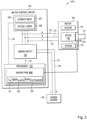
- Figure 2 illustrates an electric motor system 200 based on the electric motor system 100 described above in relation to Figure 1 but with the motor 102 comprising a rotor speed sensor 201.
- a rotor speed signal from the rotor speed sensor 201 is transmitted to the detector 220.
- the detector 220 may be configured to perform the same operations as the sensorless locked rotor detector together with a further function to detect a fault in the current measurement circuit 107 based on the above mentioned BEMF values together with a demanded rotor speed and a measured rotor speed.
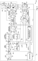
- FIG 3 illustrates a more detailed schematic diagram of the electric motor system 200 of Figure 2 , indicating in more detail the components of the motor control circuit 101, including the detector 280, motor drive circuit 105 and measurement circuits 106.
- the motor drive circuit 105 and measurement circuits 106 are distributed among the components shown in Figure 3 , with the measurement circuits comprising the Clarke transformation block 241, Park transformation block 242, and BEMF observer 271.
- Operation of the system 200 is similar to that disclosed in EP16190311A1 with the addition of a required or demanded speed input ⁇ req and a measured rotor speed input ⁇ meas input to the detector 280 together with the outputs of estimated voltage value ê ⁇ and estimated speed value ⁇ from the BEMF observer 271.
- the electric motor system 200 comprises control system elements 101 for providing fault detection based on BEMF observation with rotor speed estimation together with measured and requested speed values.
- the motor control circuit 101 includes ramp block 231, speed control block 232, quadrature-current (Q-current) control torque block 233, field control block 234, direct-current (D-current) control flux block 235, inverse Park transformation block 236, direct-current (DC) bus ripple elimination block 237, space vector modulation block 238, alternating-current-to-direct-current (AC-to-DC) power conversion block 239, inverter block 240, Clarke transformation block 241, Park transformation block 242, and BEMF tracking observer block 271 for estimating position and speed.
- the ramp block 231 receives a requested angular velocity signal ⁇ req at input 247 and provides an output 248 to adjustment block 270.
- Adjustment block 270 receives an estimated angular velocity signal ⁇ at output 249 of BEMF observer block 271. Adjustment block 270 subtracts ⁇ from ⁇ req to provide an angular velocity control signal to speed control block 232 at output 250.
- Speed control block 232 may be implemented, for example, using a proportional integral (PI) controller.
- Speed control block 232 provides an output signal to adjustment block 245 at output 251. Adjustment block 245 receives a signal from Park transformation block 242 at output 252.
- Adjustment block 245 subtracts the signal at output 252 from the signal at output 251 to provide a signal at output 253 to Q-current control torque block 233.
- Q-current control torque block 233 may be implemented, for example, using a PI controller.
- Q-current control torque block 233 provides a signal Uq at output 254 to inverse Park transformation block 236.
- the signal Uq represents the q coordinate component for the rotor related orthogonal coordinate reference frame system (d,q).
- Field control block 234 provides a field control signal to adjustment block 246 at output 255.
- Adjustment block 246 receives a motor current vector signal i d from Park transformation block 242 at output 256, where i d is the d coordinate component that is collinear to the rotor flux d coordinate.
- Adjustment block 246 subtracts the i d signal at output 256 from the field control signal at output 255 and provides a signal at output 257 to D-current control flux block 235.
- D-current control flux block 235 may be implemented, for example, using PI controller.
- D-current control flux block 235 provides a signal Ud at output 258 to inverse Park transformation block 236. In this case, the signal Ud represents the d coordinate component for the rotor related orthogonal coordinate reference frame system (d,q).
- Inverse Park transformation block 236 provides a signal U ⁇ at output 259 to DC bus ripple elimination block 237 and to the BEMF observer block 271, and also provides a signal U ⁇ at output 260 to DC bus ripple elimination block 237 and to the BEMF observer block 271.
- the signals U ⁇ , U ⁇ represent orthogonal coordinate components for the stator related orthogonal coordinate reference frame system ( ⁇ , ⁇ ).
- DC bus ripple elimination block 237 receives a signal Udcbus from output 265 of AC-to-DC power conversion block 239.
- DC bus ripple elimination block 237 provides compensation for ripple on the signal Udcbus and provides signals at outputs 261 and 262 to space vector modulation block 238.
- Space vector modulation block 238 provides pulse width modulation (PWM) motor drive signals PWM a,b,c to inverter block 240 at outputs 263.
- a line conductor 117 provides a line voltage to AC-to-DC power conversion block 239.
- a neutral conductor 118 provides a neutral voltage to AC-to-DC power conversion block 239.
- AC-to-DC power conversion block 239 provides DC voltages to inverter block 240 at one or more outputs 265 which are filtered using DC bus capacitor 264 across the 20 outputs.
- Inverter block 240 provides motor drive signals at conductors 112, 113, and 114 to electric motor 102 according to PWM motor drive signals PWM a,b,c .
- Clarke transformation block 241 provides signals i ⁇ and i ⁇ to Park transformation block 242 and to BEMF observer block 271 at outputs 266 and 267.
- Park transformation block 242 receives sin, cos( ⁇ ) -- the sine and cosine of the estimated the rotor flux angle ⁇ relative to stator phase -- at output 269 from BEMF observer block 271.
- Park transformation block 242 provides a d component motor current vector signal (e.g., i d ) at output 256 to adjustment block 246 and a q component motor current vector signal (e.g., i q ) at output 252 to adjustment block 245, where the d coordinate component of the motor current vector i d is collinear to the rotor flux d coordinate, and where the q coordinate component of the motor current vector i q is orthogonal to the rotor flux d coordinate.
- BEMF observer block 271 provides estimated angular velocity signal ⁇ to adjustment block 270 and to position and speed observer block 271 at output 249.
- BEMF observer block 271 also provides sin, cos( ⁇ ) at output 269 to inverse Park transformation block 236 and to Park transformation block 242.
- the BEMF observer block 271 provides estimated BEMF signal value ê ⁇ at output 272, though this value may also be used by the BEMF observer block 271 to generate the angle error ⁇ error .
- the motor 102 is provided with a position or rotation sensor 201, the output from which provides a measured rotor speed signal ⁇ meas .
- the detector 280 also generates an estimated angular velocity signal ⁇ (which specifies the rotor angular speed) and one or more of the BEMF voltage values ê ⁇ and ê ⁇ . Using one or more of these estimated quantities, detector 280 may execute one or more algorithms to derive a BEMF error threshold value (BEMF ErrorThreshold ) and a filtered BEMF difference value (BEMF ErrorFilt ) for processing with the estimated rotor angular speed value and measures rotor speed signal to detect one or more types of faults.
- BEMF ErrorThreshold BEMF error threshold value
- BEMF ErrorFilt filtered BEMF difference value
- EP16190311A1 describes the use of the BEMF error threshold value to determine a blocked rotation fault without the use of a position or rotation sensor on the motor.
- a motor speed sensor 201 can be used in combination with the outputs from the BEMF observer 271.
- Figure 4 illustrates an example of a series of measured and calculated values for a motor control system in which a fault may be determined using a measured motor speed in combination with calculated BEMF values.
- Figure 4 illustrates motor speed, calculated BEMF voltages, motor torque and motor currents for a simulated series of operations covering a startup period 401, a no-load period 402, a transient loaded period 403 and a fault injection period 404.
- the motor speed demand signal 405 rises and the measured and estimated motor speeds 406 (which are indistinguishable in Figure 4 due to overlap) rise along with the demand signal 405.
- the calculated BEMF values 407, 408, 409 change accordingly.
- a lower BEMF bound 409 and an upper BEMF bound 408 lie either side of a calculated BEMF value 407 during this period and during the subsequent non-load period 402 and load transient period 403.
- the upper and lower bounds 408, 409 define the BEMF error threshold and the calculated BEMF value 407 is the estimated BEMF signal ê ⁇ , as described in more detail in EP16190311A1 .
- a gradual gain fault is introduced, which leads the estimated BEMF signal ê ⁇ to move outside the BEMF error threshold defined by the upper and lower bounds 408, 409.
- a fault may be detected if the estimated BEMF signal 407 lies outside the threshold region defined by upper and lower bounds 408, 409 or if the estimated rotor angular speed value 406 falls below a minimum stall speed.
- Another type of fault may be detected if the measured rotor angular speed value 406 differs from the required rotor speed ⁇ req or estimated rotor speed ⁇ by no more than a predefined amount, for example within +/- 5% or +/-10%.
- a measure of the actual rotor speed is required for determination of such faults, which may relate to faults within the motor control circuit 101 rather than in the motor 102.
- Such faults may for example result from a gain or offset error in the current measurement circuit 107, which may be gradual or abrupt, or from an input to the current measurement circuit 107 being disconnected.
- Such faults can be detected when the estimated BEMF signal lies outside the BEMF threshold defined by the upper and lower bounds 408, 409 while the measured rotor speed value 406 is within a rotor speed error threshold.
- a fault in the motor control circuit may be detected by the detector 280 when the estimated BEMF signal ê ⁇ lies outside of a calculated BEMF error threshold and the measured rotor angular speed is within a rotor speed error threshold.
- the fault may for example be indicated, as shown in Figure 4 , by the measured rotor speed 406 being maintained after injection of the fault (i.e. at the start of the fault injection period 404) while the estimated BEMF value 407 falls outside the BEMF error threshold.
- the estimated BEMF signal 407 rises above the upper BEMF bound 408 within around 50 ms of the fault being injected, the calculated torque 411 rises above the measured torque 410 and the measured currents 413 begin to rise, while the measured rotor speed 406 remains constant.
- a fault may be indicated by the calculated torque and measured currents rising, falling or oscillating while the measured speed is maintained within the rotor speed error threshold.
- An advantage of determining a fault in the motor control circuit using a combination of the estimated BEMF signal and a measured rotor speed is that the fault can be detected prior to the motor exhibiting any changes that may result from the error. Any damage that might result from the fault could therefore be prevented by detecting the fault early and, for example, disabling the motor.
- Figure 5 illustrates a schematic diagram of a method of detecting a fault in a PMSM control circuit during operation of the PMSM.
- the detector 280 receives an estimated BEMF value ê ⁇ and an estimated rotor speed value ⁇ from the BEMF observer 271, a measured rotor speed ⁇ meas from the rotor speed sensor 201 and a required rotor speed ⁇ req from the driving circuit 105.
- the detector 280 then calculates a BEMF error threshold, BEMF ErrorThreshold and a rotor speed threshold (step 502), the rotor speed threshold being determined from either or both of the estimated rotor speed value ⁇ and the required rotor speed ⁇ req .
- the detector 280 compares the estimated BEMF value ê ⁇ to the BEMF error threshold value (step 503) and the measured rotor speed to the rotor speed threshold. If the estimated BEMF value ê ⁇ is outside the BEMF error threshold and the measured rotor speed ⁇ meas is within the rotor speed threshold, a fault is detected (step 504). The detector 280 may then disable the motor and/or output a fault indication (step 505).
- fault detection processes may also operate along with the above described process, for example to monitor the measured rotor speed compared to the required motor speed to detect a locked rotor fault.
Landscapes
- Engineering & Computer Science (AREA)
- Power Engineering (AREA)
- Control Of Motors That Do Not Use Commutators (AREA)
- Control Of Ac Motors In General (AREA)
- Control Of Electric Motors In General (AREA)
Abstract
Description
- The disclosure relates generally to the field of electric motors, and in particular to fault detection in an electric motor controller.
- Permanent Magnet Synchronous Motors (PMSM) or Brushless DC (BLDC) motors are increasingly popular electric motor designs, which replaces wear-prone brushed DC motors with an electronic controller that improves the reliability of the unit and reduces the footprint and size, making PMSMs or BLDC motors suitable for applications with restricted space. Sensorless motor control techniques may be used to detect a motor component position status for such motors. This may be done by detecting the potential or electromotive force (EMF) generated in the windings which gives rise to secondary magnetic field that opposes the original change in magnetic flux driving the motor's rotation. In resisting the motor's natural movement, the EMF is referred to as a back EMF, BEMF. However, sensorless motor control techniques have a drawback that a rotor mechanical block or stall condition may not be recognized by the sensorless algorithm. The inability to detect a locked or stopped rotor presents potential application safety concerns which are increasingly required for household motor control application standards, such as IEC 60730 ("Automatic electrical controls for household and similar use") or IEC 60335-1 ("House and Similar Electrical appliances"). As a result, some existing solutions for detecting locked rotor conditions are extremely difficult at a practical level.
-
EP16190311A1 - According to a first aspect there is provided an electric motor controller comprising:
- a driver circuit configured to drive an electric motor in response to a received speed demand signal;
- a measurement circuit configured to measure current through windings of the electric motor, the measurement circuit comprising a back emf, BEMF, observer configured to determine an estimated BEMF value, a BEMF error threshold and an estimated rotor angular speed value from the measured currents;
- a detector circuit configured to receive the rotor speed demand signal, the estimated BEMF value, the BEMF error threshold, the estimated rotor angular speed value and a measured rotor speed from a rotor speed sensor on the electric motor and to detect a fault in the electric motor controller if the estimated BEMF value lies outside the BEMF error threshold and the measured rotor speed is within a defined rotor speed error threshold.
- The detector circuit may be configured to cause the driver circuit to disable the motor if a fault is detected.
- The detector circuit may be configured to output a fault indication if a fault is detected.
- The rotor speed error threshold may be defined from the rotor speed demand signal.
- The rotor speed error threshold may be a range within around +/-5% or +/-10% of the rotor speed demand signal.
- According to a second aspect there is provided an electric motor system comprising:
- an electric motor having a stator, a rotor and a rotor speed sensor connected to the rotor; and
- an electric motor controller according to the first aspect.
- The electric motor may be a permanent magnet synchronous motor.
- According to a third aspect there is provided a method of detecting a fault in an electric motor controller, the electric motor controller comprising:
- a driver circuit configured to drive an electric motor in response to a received speed demand signal;
- a measurement circuit configured to measure current through windings of the electric motor, the measurement circuit comprising a back emf, BEMF, observer configured to determine an estimated BEMF value, a BEMF error threshold and an estimated rotor angular speed value from the measured currents; and
- a detector circuit configured to receive the rotor speed demand signal, the estimated BEMF value, the BEMF error threshold, the estimated rotor angular speed value and a measured rotor speed from a rotor speed sensor on the electric motor,
- the method comprising the detector circuit detecting a fault in the electric motor controller if the estimated BEMF value lies outside the BEMF error threshold and the measured rotor speed is within a defined rotor speed error threshold.
- The detector circuit may cause the driver circuit to disable the motor if a fault is detected.
- The detector circuit may output a fault indication if a fault is detected.
- The rotor speed error threshold may be defined from the rotor speed demand signal.
- The rotor speed error threshold may be a range within around +/-5% or +/-10% of the rotor speed demand signal.
- These and other aspects of the invention will be apparent from, and elucidated with reference to, the embodiments described hereinafter.
- Embodiments will be described, by way of example only, with reference to the drawings, in which:
-
Figure 1 is a schematic block diagram of an electric motor system comprising a motor control circuit utilizing a sensorless locked rotor detector; -
Figure 2 is a schematic block diagram of an electric motor system comprising a motor control circuit utilizing a motor speed sensor and a detector; -
Figure 3 is a more detailed schematic block diagram of the electric motor system ofFigure 2 ; -
Figure 4 is an example series of simulated plots of motor speed, calculated BEMF, motor torque and motor currents as a function of time; and -
Figure 5 is a schematic flow diagram illustrating an example method of detecting a fault in an electric motor controller. - It should be noted that the Figures are diagrammatic and not drawn to scale. Relative dimensions and proportions of parts of these Figures have been shown exaggerated or reduced in size, for the sake of clarity and convenience in the drawings. The same reference signs are generally used to refer to corresponding or similar feature in modified and different embodiments.
-
Figure 1 , reproduced fromEP16190311A1 electric motor system 100, which uses a sensorless lockedrotor detector 120. Theelectric motor system 100 includes amotor control circuit 101,motor 102, andpower source 119. Themotor control circuit 101 includes aprocessor 103,driver circuit 105, andmeasurement circuits 106.Processor 103 includes a sensorless lockedrotor detector 120, which may be implemented in hardware or in software by accessing or including memory to store the sensorless lockedrotor detector 120. In whatever form implemented, the sensorless lockedrotor detector 120 may include first, second andthird calculation modules measurement circuits 106. Thefirst calculation module 121 computes the second estimated BEMF voltage value êq as the q coordinate component of an estimated BEMF value. Thesecond calculation module 122 computes the filtered BEMF difference value as the filtered difference between the first estimated BEMF voltage value êδ and the second estimated BEMF voltage value êq. Thethird calculation module 123 computes the BEMF error threshold value as a function of the estimated rotor angular speed value ω̂, subject to a minimum or baseline threshold BEMF value. -
Measurement circuits 106 include acurrent measurement circuit 107 and a DC busvoltage measurement circuit 108. Themotor 102 includes arotor 109,stator 110 andshaft 111, theshaft 111 being mechanically coupled to therotor 109. Windings are disposed in themotor 102, which are connected to themotor control circuit 101 byconductors conductors driver circuit 105 and to inputs of themeasurement circuits 106. Themeasurement circuits 106 are connected to theprocessor 103 by one ormore connection lines 116. Theprocessor 103 is connected to thedriver circuit 105 by one ormore connection lines 115 to allow theprocessor 103 to control thedriver circuit 105. Thepower source 119 is connected to thedriver circuit 105 via live (L) and neutral (N)conductors driver circuit 105. Thepower source 119 may be provided with more than two outputs, for example in a three phase system. Thecurrent measurement circuit 107 obtains one or more current measurements ia, ib, ic of themotor 102 windings. The DC busvoltage measurement circuit 108 obtains corresponding voltage measurements of themotor 102 windings. Such measurements can be complex measurements, including a direct (d) component and a quadrature (q) component. -
Figure 2 illustrates anelectric motor system 200 based on theelectric motor system 100 described above in relation toFigure 1 but with themotor 102 comprising arotor speed sensor 201. A rotor speed signal from therotor speed sensor 201 is transmitted to thedetector 220. Thedetector 220 may be configured to perform the same operations as the sensorless locked rotor detector together with a further function to detect a fault in thecurrent measurement circuit 107 based on the above mentioned BEMF values together with a demanded rotor speed and a measured rotor speed. -
Figure 3 illustrates a more detailed schematic diagram of theelectric motor system 200 ofFigure 2 , indicating in more detail the components of themotor control circuit 101, including thedetector 280,motor drive circuit 105 andmeasurement circuits 106. Themotor drive circuit 105 andmeasurement circuits 106 are distributed among the components shown inFigure 3 , with the measurement circuits comprising theClarke transformation block 241,Park transformation block 242, and BEMF observer 271. Operation of thesystem 200 is similar to that disclosed inEP16190311A1 detector 280 together with the outputs of estimated voltage value êδ and estimated speed value ω̂ from the BEMF observer 271. - The
electric motor system 200 comprisescontrol system elements 101 for providing fault detection based on BEMF observation with rotor speed estimation together with measured and requested speed values. Themotor control circuit 101 includesramp block 231,speed control block 232, quadrature-current (Q-current)control torque block 233,field control block 234, direct-current (D-current)control flux block 235, inversePark transformation block 236, direct-current (DC) busripple elimination block 237, spacevector modulation block 238, alternating-current-to-direct-current (AC-to-DC)power conversion block 239, inverter block 240,Clarke transformation block 241,Park transformation block 242, and BEMF tracking observer block 271 for estimating position and speed. - In operation, the
ramp block 231 receives a requested angular velocity signal ωreq atinput 247 and provides anoutput 248 toadjustment block 270.Adjustment block 270 receives an estimated angular velocity signal ω̂ atoutput 249 of BEMF observer block 271.Adjustment block 270 subtracts ω̂ from ωreq to provide an angular velocity control signal to speedcontrol block 232 atoutput 250.Speed control block 232 may be implemented, for example, using a proportional integral (PI) controller.Speed control block 232 provides an output signal to adjustment block 245 atoutput 251.Adjustment block 245 receives a signal fromPark transformation block 242 atoutput 252.Adjustment block 245 subtracts the signal atoutput 252 from the signal atoutput 251 to provide a signal atoutput 253 to Q-currentcontrol torque block 233. Q-currentcontrol torque block 233 may be implemented, for example, using a PI controller. Q-currentcontrol torque block 233 provides a signal Uq atoutput 254 to inversePark transformation block 236. In this case, the signal Uq represents the q coordinate component for the rotor related orthogonal coordinate reference frame system (d,q). -
Field control block 234 provides a field control signal to adjustment block 246 atoutput 255.Adjustment block 246 receives a motor current vector signal id fromPark transformation block 242 atoutput 256, where id is the d coordinate component that is collinear to the rotor flux d coordinate.Adjustment block 246 subtracts the id signal atoutput 256 from the field control signal atoutput 255 and provides a signal atoutput 257 to D-currentcontrol flux block 235. D-currentcontrol flux block 235 may be implemented, for example, using PI controller. D-currentcontrol flux block 235 provides a signal Ud atoutput 258 to inversePark transformation block 236. In this case, the signal Ud represents the d coordinate component for the rotor related orthogonal coordinate reference frame system (d,q). - Inverse
Park transformation block 236 provides a signal Uα atoutput 259 to DC busripple elimination block 237 and to the BEMF observer block 271, and also provides a signal Uβ atoutput 260 to DC busripple elimination block 237 and to the BEMF observer block 271. In this case, the signals Uα, Uβ represent orthogonal coordinate components for the stator related orthogonal coordinate reference frame system (α, β). DC busripple elimination block 237 receives a signal Udcbus fromoutput 265 of AC-to-DCpower conversion block 239. DC busripple elimination block 237 provides compensation for ripple on the signal Udcbus and provides signals atoutputs 261 and 262 to spacevector modulation block 238. Spacevector modulation block 238 provides pulse width modulation (PWM) motor drive signals PWMa,b,c to inverter block 240 atoutputs 263. Aline conductor 117 provides a line voltage to AC-to-DCpower conversion block 239. Aneutral conductor 118 provides a neutral voltage to AC-to-DCpower conversion block 239. AC-to-DCpower conversion block 239 provides DC voltages to inverter block 240 at one ormore outputs 265 which are filtered usingDC bus capacitor 264 across the 20 outputs. Inverter block 240 provides motor drive signals atconductors electric motor 102 according to PWM motor drive signals PWMa,b,c. -
Conductors electric motor 102 provide signals (e.g., ia, ib and ic) to inputs ofClarke transformation block 241.Clarke transformation block 241 provides signals iα and iβ toPark transformation block 242 and to BEMF observer block 271 atoutputs Park transformation block 242 receives sin, cos(θ̂) -- the sine and cosine of the estimated the rotor flux angle θ̂ relative to stator phase -- atoutput 269 from BEMF observer block 271.Park transformation block 242 provides a d component motor current vector signal (e.g., id) atoutput 256 to adjustment block 246 and a q component motor current vector signal (e.g., iq) atoutput 252 to adjustment block 245, where the d coordinate component of the motor current vector id is collinear to the rotor flux d coordinate, and where the q coordinate component of the motor current vector iq is orthogonal to the rotor flux d coordinate. BEMF observer block 271 provides estimated angular velocity signal ω̂ to adjustment block 270 and to position and speed observer block 271 atoutput 249. BEMF observer block 271 also provides sin, cos(θ̂) atoutput 269 to inversePark transformation block 236 and toPark transformation block 242. In addition, the BEMF observer block 271 provides estimated BEMF signal value êδ atoutput 272, though this value may also be used by the BEMF observer block 271 to generate the angle error θerror. - The
motor 102 is provided with a position orrotation sensor 201, the output from which provides a measured rotor speed signal ωmeas. Thedetector 280 also generates an estimated angular velocity signal ω̂ (which specifies the rotor angular speed) and one or more of the BEMF voltage values êδ and êγ. Using one or more of these estimated quantities,detector 280 may execute one or more algorithms to derive a BEMF error threshold value (BEMFErrorThreshold) and a filtered BEMF difference value (BEMFErrorFilt) for processing with the estimated rotor angular speed value and measures rotor speed signal to detect one or more types of faults. - Further details of the operation of the BEMF observer 271 are described in
EP16190311A1 motor speed sensor 201 can be used in combination with the outputs from the BEMF observer 271. -
Figure 4 illustrates an example of a series of measured and calculated values for a motor control system in which a fault may be determined using a measured motor speed in combination with calculated BEMF values.Figure 4 illustrates motor speed, calculated BEMF voltages, motor torque and motor currents for a simulated series of operations covering astartup period 401, a no-load period 402, a transient loadedperiod 403 and afault injection period 404. During thestartup period 401, the motorspeed demand signal 405 rises and the measured and estimated motor speeds 406 (which are indistinguishable inFigure 4 due to overlap) rise along with thedemand signal 405. Along with this, the calculated BEMF values 407, 408, 409 change accordingly. A lower BEMF bound 409 and an upper BEMF bound 408 lie either side of acalculated BEMF value 407 during this period and during the subsequentnon-load period 402 and loadtransient period 403. The upper andlower bounds calculated BEMF value 407 is the estimated BEMF signal êδ , as described in more detail inEP16190311A1 fault injection period 404, a gradual gain fault is introduced, which leads the estimated BEMF signal êδ to move outside the BEMF error threshold defined by the upper andlower bounds - As in
EP16190311A1 lower bounds angular speed value 406 falls below a minimum stall speed. Another type of fault may be detected if the measured rotorangular speed value 406 differs from the required rotor speed ωreq or estimated rotor speed ω̂ by no more than a predefined amount, for example within +/- 5% or +/-10%. A measure of the actual rotor speed is required for determination of such faults, which may relate to faults within themotor control circuit 101 rather than in themotor 102. Such faults may for example result from a gain or offset error in thecurrent measurement circuit 107, which may be gradual or abrupt, or from an input to thecurrent measurement circuit 107 being disconnected. Such faults can be detected when the estimated BEMF signal lies outside the BEMF threshold defined by the upper andlower bounds rotor speed value 406 is within a rotor speed error threshold. In a general aspect therefore, a fault in the motor control circuit may be detected by thedetector 280 when the estimated BEMF signal êδ lies outside of a calculated BEMF error threshold and the measured rotor angular speed is within a rotor speed error threshold. - The fault may for example be indicated, as shown in
Figure 4 , by the measuredrotor speed 406 being maintained after injection of the fault (i.e. at the start of the fault injection period 404) while the estimatedBEMF value 407 falls outside the BEMF error threshold. As the estimated BEMF signal 407 rises above the upper BEMF bound 408 within around 50 ms of the fault being injected, the calculatedtorque 411 rises above the measuredtorque 410 and the measuredcurrents 413 begin to rise, while the measuredrotor speed 406 remains constant. In other examples, a fault may be indicated by the calculated torque and measured currents rising, falling or oscillating while the measured speed is maintained within the rotor speed error threshold. - An advantage of determining a fault in the motor control circuit using a combination of the estimated BEMF signal and a measured rotor speed is that the fault can be detected prior to the motor exhibiting any changes that may result from the error. Any damage that might result from the fault could therefore be prevented by detecting the fault early and, for example, disabling the motor.
-
Figure 5 illustrates a schematic diagram of a method of detecting a fault in a PMSM control circuit during operation of the PMSM. In afirst step 501, thedetector 280 receives an estimated BEMF value êδ and an estimated rotor speed value ω̂ from the BEMF observer 271, a measured rotor speed ωmeas from therotor speed sensor 201 and a required rotor speed ωreq from the drivingcircuit 105. Thedetector 280 then calculates a BEMF error threshold, BEMFErrorThreshold and a rotor speed threshold (step 502), the rotor speed threshold being determined from either or both of the estimated rotor speed value ω̂ and the required rotor speed ωreq. Thedetector 280 then compares the estimated BEMF value êδ to the BEMF error threshold value (step 503) and the measured rotor speed to the rotor speed threshold. If the estimated BEMF value êδ is outside the BEMF error threshold and the measured rotor speed ωmeas is within the rotor speed threshold, a fault is detected (step 504). Thedetector 280 may then disable the motor and/or output a fault indication (step 505). - Other fault detection processes may also operate along with the above described process, for example to monitor the measured rotor speed compared to the required motor speed to detect a locked rotor fault.
- From reading the present disclosure, other variations and modifications will be apparent to the skilled person. Such variations and modifications may involve equivalent and other features which are already known in the art of memory systems, and which may be used instead of, or in addition to, features already described herein.
- Although the appended claims are directed to particular combinations of features, it should be understood that the scope of the disclosure of the present invention also includes any novel feature or any novel combination of features disclosed herein either explicitly or implicitly or any generalisation thereof, whether or not it relates to the same invention as presently claimed in any claim and whether or not it mitigates any or all of the same technical problems as does the present invention.
- Features which are described in the context of separate embodiments may also be provided in combination in a single embodiment. Conversely, various features which are, for brevity, described in the context of a single embodiment, may also be provided separately or in any suitable sub-combination. The applicant hereby gives notice that new claims may be formulated to such features and/or combinations of such features during the prosecution of the present application or of any further application derived therefrom.
- For the sake of completeness it is also stated that the term "comprising" does not exclude other elements or steps, the term "a" or "an" does not exclude a plurality, a single processor or other unit may fulfil the functions of several means recited in the claims and reference signs in the claims shall not be construed as limiting the scope of the claims.
Claims (12)
- An electric motor controller (101) comprising:a driver circuit (105) configured to drive an electric motor (102) in response to a received speed demand signal (ωreq);a measurement circuit (106) configured to measure current through windings (112, 113, 114) of the electric motor (102), the measurement circuit comprising a back emf, BEMF, observer (271) configured to determine an estimated BEMF value (êδ ), a BEMF error threshold and an estimated rotor angular speed value (ω̂) from the measured currents;a detector circuit (280) configured to receive the rotor speed demand signal (ωreq), the estimated BEMF value (êδ ), the BEMF error threshold, the estimated rotor angular speed value (ω̂) and a measured rotor speed (ωmeas) from a rotor speed sensor (201) on the electric motor (102) and to detect a fault in the electric motor controller (101) if the estimated BEMF value (êδ ) lies outside the BEMF error threshold and the measured rotor speed (ωmeas) is within a defined rotor speed error threshold.
- The electric motor controller (101) of claim 1, wherein the detector circuit (280) is configured to cause the driver circuit (105) to disable the motor if a fault is detected.
- The electric motor controller (101) of claim 1 or claim 2, wherein the detector circuit (280) is configured to output a fault indication if a fault is detected.
- The electric motor controller (101) of any preceding claim, wherein the rotor speed error threshold is defined from the rotor speed demand signal (ωreq).
- The electric motor controller (101) of claim 4, wherein the rotor speed error threshold is a range within around +/-5% or +/-10% of the rotor speed demand signal (ωreq).
- An electric motor system (200) comprising:an electric motor (102) having a stator (110), a rotor (109) and a rotor speed sensor (201) connected to the rotor (109); andan electric motor controller (101) according to any one of claims 1 to 5.
- The electric motor system (200) of claim 6, wherein the electric motor (102) is a permanent magnet synchronous motor.
- A method of detecting a fault in an electric motor controller (101), the electric motor controller (101) comprising:a driver circuit (105) configured to drive an electric motor (102) in response to a received speed demand signal (ωreq);a measurement circuit (106) configured to measure current through windings (112, 113, 114) of the electric motor (102), the measurement circuit comprising a back emf, BEMF, observer (271) configured to determine an estimated BEMF value (êδ ), a BEMF error threshold and an estimated rotor angular speed value (ω̂) from the measured currents; anda detector circuit (280) configured to receive the rotor speed demand signal (ωreq), the estimated BEMF value (êδ ), the BEMF error threshold, the estimated rotor angular speed value (ω̂) and a measured rotor speed (ωmeas) from a rotor speed sensor (201) on the electric motor (102),the method comprising the detector circuit (280) detecting a fault in the electric motor controller (101) if the estimated BEMF value (êδ ) lies outside the BEMF error threshold and the measured rotor speed (ωmeas) is within a defined rotor speed error threshold.
- The method of claim 8, wherein the detector circuit (280) causes the driver circuit (105) to disable the motor if a fault is detected.
- The method of claim 8 or claim 9, wherein the detector circuit (280) outputs a fault indication if a fault is detected.
- The method of any one of claims 8 to 11, wherein the rotor speed error threshold is defined from the rotor speed demand signal (ωreq).
- The method of claim 11, wherein the rotor speed error threshold is a range within around +/-5% or +/-10% of the rotor speed demand signal (ωreq).
Priority Applications (2)
| Application Number | Priority Date | Filing Date | Title |
|---|---|---|---|
| EP21211406.0A EP4187776B1 (en) | 2021-11-30 | 2021-11-30 | Electric motor fault detection |
| US18/059,337 US12224692B2 (en) | 2021-11-30 | 2022-11-28 | Electric motor fault detection |
Applications Claiming Priority (1)
| Application Number | Priority Date | Filing Date | Title |
|---|---|---|---|
| EP21211406.0A EP4187776B1 (en) | 2021-11-30 | 2021-11-30 | Electric motor fault detection |
Publications (2)
| Publication Number | Publication Date |
|---|---|
| EP4187776A1 true EP4187776A1 (en) | 2023-05-31 |
| EP4187776B1 EP4187776B1 (en) | 2024-10-02 |
Family
ID=78819983
Family Applications (1)
| Application Number | Title | Priority Date | Filing Date |
|---|---|---|---|
| EP21211406.0A Active EP4187776B1 (en) | 2021-11-30 | 2021-11-30 | Electric motor fault detection |
Country Status (2)
| Country | Link |
|---|---|
| US (1) | US12224692B2 (en) |
| EP (1) | EP4187776B1 (en) |
Citations (3)
| Publication number | Priority date | Publication date | Assignee | Title |
|---|---|---|---|---|
| EP3185411A1 (en) * | 2015-11-03 | 2017-06-28 | NXP USA, Inc. | Method and apparatus for motor lock or stall detection |
| US20180115263A1 (en) * | 2016-10-20 | 2018-04-26 | Texas Instruments Incorporated | Converged motor drive control for brushless dc motor |
| US20200169204A1 (en) * | 2018-11-23 | 2020-05-28 | Texas Instruments Incorporated | Low Speed Sensorless Rotor Angle Estimation |
Family Cites Families (10)
| Publication number | Priority date | Publication date | Assignee | Title |
|---|---|---|---|---|
| US5729113A (en) * | 1997-01-21 | 1998-03-17 | General Electric Company | Sensorless rotor velocity estimation for induction motors |
| CA2513550A1 (en) * | 2003-01-24 | 2004-08-12 | Tecumseh Products Company | Brushless and sensorless dc motor control system with locked and stopped rotor detection |
| GB0916543D0 (en) * | 2009-09-21 | 2009-10-28 | Melexis Tessenderlo Nv | Control of sinusoidally driven brushless dc (bldc) motors |
| US20140097777A1 (en) * | 2012-10-04 | 2014-04-10 | Marvell World Trade Ltd. | Driving a rotating device based on a combination of speed detection by a sensor and sensor-less speed detection |
| CN103248307B (en) | 2013-05-24 | 2015-05-20 | 哈尔滨工业大学 | Fault diagnosis method for current sensor in induction motor speed regulating system |
| US9809247B2 (en) | 2015-01-30 | 2017-11-07 | Steering Solutions Ip Holding Corporation | Motor control current sensor loss of assist mitigation for electric power steering |
| DE102015102565A1 (en) * | 2015-02-23 | 2016-08-25 | Ebm-Papst Mulfingen Gmbh & Co. Kg | Sensorless commutation method |
| JP2017060276A (en) | 2015-09-16 | 2017-03-23 | 富士電機株式会社 | Three-phase inverter device |
| WO2020133113A1 (en) * | 2018-12-27 | 2020-07-02 | 广东美的白色家电技术创新中心有限公司 | Determination method and apparatus for bldc counter-electromotive force zero crossing point threshold, and storage medium |
| US11764710B2 (en) * | 2021-06-30 | 2023-09-19 | Texas Instruments Incorporated | Automatic transition of motor controller from open-loop control to closed-loop control |
-
2021
- 2021-11-30 EP EP21211406.0A patent/EP4187776B1/en active Active
-
2022
- 2022-11-28 US US18/059,337 patent/US12224692B2/en active Active
Patent Citations (3)
| Publication number | Priority date | Publication date | Assignee | Title |
|---|---|---|---|---|
| EP3185411A1 (en) * | 2015-11-03 | 2017-06-28 | NXP USA, Inc. | Method and apparatus for motor lock or stall detection |
| US20180115263A1 (en) * | 2016-10-20 | 2018-04-26 | Texas Instruments Incorporated | Converged motor drive control for brushless dc motor |
| US20200169204A1 (en) * | 2018-11-23 | 2020-05-28 | Texas Instruments Incorporated | Low Speed Sensorless Rotor Angle Estimation |
Also Published As
| Publication number | Publication date |
|---|---|
| US20230170835A1 (en) | 2023-06-01 |
| EP4187776B1 (en) | 2024-10-02 |
| US12224692B2 (en) | 2025-02-11 |
Similar Documents
| Publication | Publication Date | Title |
|---|---|---|
| US10075107B2 (en) | Method and apparatus for motor lock or stall detection | |
| US6392418B1 (en) | Torque current comparison for current reasonableness diagnostics in a permanent magnet electric machine | |
| US9825579B2 (en) | Temperature estimating apparatus for synchronous motor | |
| US6694287B2 (en) | Phase angle diagnostics for sinusoidal controlled electric machine | |
| US8269436B2 (en) | Motor control device | |
| RU2561879C2 (en) | Control device of synchronous machine with permanent magnets | |
| US8185342B2 (en) | Estimating rotor angular position and velocity and verifying accuracy of position sensor outputs | |
| US8664901B2 (en) | Method and system for estimating electrical angular speed of a permanent magnet machine | |
| CN110518857A (en) | Locked rotor state judgment method of position-sensor-free vector control permanent magnet synchronous motor | |
| US11387756B1 (en) | Motor controller with stall detection | |
| KR101989596B1 (en) | System and method for controlling motor | |
| CN118432486A (en) | Motor controller, phase failure detection method and power assembly | |
| CN111211729B (en) | Apparatus and method for detecting overload of BLDC motor | |
| JP2010239790A (en) | Rotating electrical machine control device | |
| JP3797508B2 (en) | Sensorless speed control method of permanent magnet type synchronous motor and step-out detection method thereof | |
| JP2010051151A (en) | Motor control apparatus | |
| US12224692B2 (en) | Electric motor fault detection | |
| US11031892B2 (en) | Apparatus and method for detecting overload of BLDC motor | |
| WO2001020343A1 (en) | Torque current comparison for current reasonableness diagnostics in a permanent magnet electric machine | |
| GB2375826A (en) | Method or means of estimating the DC bus voltage in an electric machine drive | |
| Otava et al. | Integrated diagnostic system for winding fault detection of the three-phase PMSM | |
| US20240356469A1 (en) | Detection method and apparatus for motor parameters | |
| JP2010252503A (en) | Position and speed sensorless controller of pm motor | |
| RU2755671C1 (en) | Monitoring apparatus for reluctance machine and method for monitoring | |
| JP2025511610A (en) | Method and device for controlling a motor using a direct flux vector control module and a constant current angular trajectory module |
Legal Events
| Date | Code | Title | Description |
|---|---|---|---|
| PUAI | Public reference made under article 153(3) epc to a published international application that has entered the european phase |
Free format text: ORIGINAL CODE: 0009012 |
|
| STAA | Information on the status of an ep patent application or granted ep patent |
Free format text: STATUS: THE APPLICATION HAS BEEN PUBLISHED |
|
| AK | Designated contracting states |
Kind code of ref document: A1 Designated state(s): AL AT BE BG CH CY CZ DE DK EE ES FI FR GB GR HR HU IE IS IT LI LT LU LV MC MK MT NL NO PL PT RO RS SE SI SK SM TR |
|
| STAA | Information on the status of an ep patent application or granted ep patent |
Free format text: STATUS: REQUEST FOR EXAMINATION WAS MADE |
|
| 17P | Request for examination filed |
Effective date: 20231130 |
|
| RBV | Designated contracting states (corrected) |
Designated state(s): AL AT BE BG CH CY CZ DE DK EE ES FI FR GB GR HR HU IE IS IT LI LT LU LV MC MK MT NL NO PL PT RO RS SE SI SK SM TR |
|
| GRAP | Despatch of communication of intention to grant a patent |
Free format text: ORIGINAL CODE: EPIDOSNIGR1 |
|
| STAA | Information on the status of an ep patent application or granted ep patent |
Free format text: STATUS: GRANT OF PATENT IS INTENDED |
|
| INTG | Intention to grant announced |
Effective date: 20240430 |
|
| GRAS | Grant fee paid |
Free format text: ORIGINAL CODE: EPIDOSNIGR3 |
|
| GRAA | (expected) grant |
Free format text: ORIGINAL CODE: 0009210 |
|
| STAA | Information on the status of an ep patent application or granted ep patent |
Free format text: STATUS: THE PATENT HAS BEEN GRANTED |
|
| AK | Designated contracting states |
Kind code of ref document: B1 Designated state(s): AL AT BE BG CH CY CZ DE DK EE ES FI FR GB GR HR HU IE IS IT LI LT LU LV MC MK MT NL NO PL PT RO RS SE SI SK SM TR |
|
| REG | Reference to a national code |
Ref country code: GB Ref legal event code: FG4D |
|
| REG | Reference to a national code |
Ref country code: CH Ref legal event code: EP |
|
| REG | Reference to a national code |
Ref country code: IE Ref legal event code: FG4D |
|
| REG | Reference to a national code |
Ref country code: DE Ref legal event code: R096 Ref document number: 602021019558 Country of ref document: DE |
|
| REG | Reference to a national code |
Ref country code: LT Ref legal event code: MG9D |
|
| REG | Reference to a national code |
Ref country code: NL Ref legal event code: MP Effective date: 20241002 |
|
| REG | Reference to a national code |
Ref country code: AT Ref legal event code: MK05 Ref document number: 1729174 Country of ref document: AT Kind code of ref document: T Effective date: 20241002 |
|
| PG25 | Lapsed in a contracting state [announced via postgrant information from national office to epo] |
Ref country code: NL Free format text: LAPSE BECAUSE OF FAILURE TO SUBMIT A TRANSLATION OF THE DESCRIPTION OR TO PAY THE FEE WITHIN THE PRESCRIBED TIME-LIMIT Effective date: 20241002 |
|
| PG25 | Lapsed in a contracting state [announced via postgrant information from national office to epo] |
Ref country code: NL Free format text: LAPSE BECAUSE OF FAILURE TO SUBMIT A TRANSLATION OF THE DESCRIPTION OR TO PAY THE FEE WITHIN THE PRESCRIBED TIME-LIMIT Effective date: 20241002 |
|
| PG25 | Lapsed in a contracting state [announced via postgrant information from national office to epo] |
Ref country code: PT Free format text: LAPSE BECAUSE OF FAILURE TO SUBMIT A TRANSLATION OF THE DESCRIPTION OR TO PAY THE FEE WITHIN THE PRESCRIBED TIME-LIMIT Effective date: 20250203 Ref country code: IS Free format text: LAPSE BECAUSE OF FAILURE TO SUBMIT A TRANSLATION OF THE DESCRIPTION OR TO PAY THE FEE WITHIN THE PRESCRIBED TIME-LIMIT Effective date: 20250202 Ref country code: HR Free format text: LAPSE BECAUSE OF FAILURE TO SUBMIT A TRANSLATION OF THE DESCRIPTION OR TO PAY THE FEE WITHIN THE PRESCRIBED TIME-LIMIT Effective date: 20241002 |
|
| PG25 | Lapsed in a contracting state [announced via postgrant information from national office to epo] |
Ref country code: FI Free format text: LAPSE BECAUSE OF FAILURE TO SUBMIT A TRANSLATION OF THE DESCRIPTION OR TO PAY THE FEE WITHIN THE PRESCRIBED TIME-LIMIT Effective date: 20241002 |
|
| PG25 | Lapsed in a contracting state [announced via postgrant information from national office to epo] |
Ref country code: BG Free format text: LAPSE BECAUSE OF FAILURE TO SUBMIT A TRANSLATION OF THE DESCRIPTION OR TO PAY THE FEE WITHIN THE PRESCRIBED TIME-LIMIT Effective date: 20241002 |
|
| PG25 | Lapsed in a contracting state [announced via postgrant information from national office to epo] |
Ref country code: ES Free format text: LAPSE BECAUSE OF FAILURE TO SUBMIT A TRANSLATION OF THE DESCRIPTION OR TO PAY THE FEE WITHIN THE PRESCRIBED TIME-LIMIT Effective date: 20241002 |
|
| PG25 | Lapsed in a contracting state [announced via postgrant information from national office to epo] |
Ref country code: NO Free format text: LAPSE BECAUSE OF FAILURE TO SUBMIT A TRANSLATION OF THE DESCRIPTION OR TO PAY THE FEE WITHIN THE PRESCRIBED TIME-LIMIT Effective date: 20250102 |
|
| PG25 | Lapsed in a contracting state [announced via postgrant information from national office to epo] |
Ref country code: GR Free format text: LAPSE BECAUSE OF FAILURE TO SUBMIT A TRANSLATION OF THE DESCRIPTION OR TO PAY THE FEE WITHIN THE PRESCRIBED TIME-LIMIT Effective date: 20250103 Ref country code: LV Free format text: LAPSE BECAUSE OF FAILURE TO SUBMIT A TRANSLATION OF THE DESCRIPTION OR TO PAY THE FEE WITHIN THE PRESCRIBED TIME-LIMIT Effective date: 20241002 Ref country code: AT Free format text: LAPSE BECAUSE OF FAILURE TO SUBMIT A TRANSLATION OF THE DESCRIPTION OR TO PAY THE FEE WITHIN THE PRESCRIBED TIME-LIMIT Effective date: 20241002 |
|
| PG25 | Lapsed in a contracting state [announced via postgrant information from national office to epo] |
Ref country code: PL Free format text: LAPSE BECAUSE OF FAILURE TO SUBMIT A TRANSLATION OF THE DESCRIPTION OR TO PAY THE FEE WITHIN THE PRESCRIBED TIME-LIMIT Effective date: 20241002 Ref country code: CZ Free format text: LAPSE BECAUSE OF FAILURE TO SUBMIT A TRANSLATION OF THE DESCRIPTION OR TO PAY THE FEE WITHIN THE PRESCRIBED TIME-LIMIT Effective date: 20241002 |
|
| PG25 | Lapsed in a contracting state [announced via postgrant information from national office to epo] |
Ref country code: RS Free format text: LAPSE BECAUSE OF FAILURE TO SUBMIT A TRANSLATION OF THE DESCRIPTION OR TO PAY THE FEE WITHIN THE PRESCRIBED TIME-LIMIT Effective date: 20250102 |
|
| REG | Reference to a national code |
Ref country code: CH Ref legal event code: PL |
|
| PG25 | Lapsed in a contracting state [announced via postgrant information from national office to epo] |
Ref country code: SM Free format text: LAPSE BECAUSE OF FAILURE TO SUBMIT A TRANSLATION OF THE DESCRIPTION OR TO PAY THE FEE WITHIN THE PRESCRIBED TIME-LIMIT Effective date: 20241002 |
|
| REG | Reference to a national code |
Ref country code: DE Ref legal event code: R097 Ref document number: 602021019558 Country of ref document: DE |
|
| PG25 | Lapsed in a contracting state [announced via postgrant information from national office to epo] |
Ref country code: MC Free format text: LAPSE BECAUSE OF FAILURE TO SUBMIT A TRANSLATION OF THE DESCRIPTION OR TO PAY THE FEE WITHIN THE PRESCRIBED TIME-LIMIT Effective date: 20241002 |
|
| PG25 | Lapsed in a contracting state [announced via postgrant information from national office to epo] |
Ref country code: DK Free format text: LAPSE BECAUSE OF FAILURE TO SUBMIT A TRANSLATION OF THE DESCRIPTION OR TO PAY THE FEE WITHIN THE PRESCRIBED TIME-LIMIT Effective date: 20241002 |
|
| PG25 | Lapsed in a contracting state [announced via postgrant information from national office to epo] |
Ref country code: LU Free format text: LAPSE BECAUSE OF NON-PAYMENT OF DUE FEES Effective date: 20241130 |
|
| REG | Reference to a national code |
Ref country code: CH Ref legal event code: PL |
|
| PG25 | Lapsed in a contracting state [announced via postgrant information from national office to epo] |
Ref country code: EE Free format text: LAPSE BECAUSE OF FAILURE TO SUBMIT A TRANSLATION OF THE DESCRIPTION OR TO PAY THE FEE WITHIN THE PRESCRIBED TIME-LIMIT Effective date: 20241002 |
|
| PG25 | Lapsed in a contracting state [announced via postgrant information from national office to epo] |
Ref country code: CH Free format text: LAPSE BECAUSE OF NON-PAYMENT OF DUE FEES Effective date: 20241130 |
|
| PG25 | Lapsed in a contracting state [announced via postgrant information from national office to epo] |
Ref country code: RO Free format text: LAPSE BECAUSE OF FAILURE TO SUBMIT A TRANSLATION OF THE DESCRIPTION OR TO PAY THE FEE WITHIN THE PRESCRIBED TIME-LIMIT Effective date: 20241002 |
|
| PG25 | Lapsed in a contracting state [announced via postgrant information from national office to epo] |
Ref country code: SK Free format text: LAPSE BECAUSE OF FAILURE TO SUBMIT A TRANSLATION OF THE DESCRIPTION OR TO PAY THE FEE WITHIN THE PRESCRIBED TIME-LIMIT Effective date: 20241002 |
|
| PG25 | Lapsed in a contracting state [announced via postgrant information from national office to epo] |
Ref country code: IT Free format text: LAPSE BECAUSE OF FAILURE TO SUBMIT A TRANSLATION OF THE DESCRIPTION OR TO PAY THE FEE WITHIN THE PRESCRIBED TIME-LIMIT Effective date: 20241002 |
|
| P01 | Opt-out of the competence of the unified patent court (upc) registered |
Free format text: CASE NUMBER: APP_29976/2025 Effective date: 20250623 |
|
| PLBE | No opposition filed within time limit |
Free format text: ORIGINAL CODE: 0009261 |
|
| STAA | Information on the status of an ep patent application or granted ep patent |
Free format text: STATUS: NO OPPOSITION FILED WITHIN TIME LIMIT |
|
| REG | Reference to a national code |
Ref country code: BE Ref legal event code: MM Effective date: 20241130 |
|
| PG25 | Lapsed in a contracting state [announced via postgrant information from national office to epo] |
Ref country code: SE Free format text: LAPSE BECAUSE OF FAILURE TO SUBMIT A TRANSLATION OF THE DESCRIPTION OR TO PAY THE FEE WITHIN THE PRESCRIBED TIME-LIMIT Effective date: 20241002 |
|
| 26N | No opposition filed |
Effective date: 20250703 |
|
| PG25 | Lapsed in a contracting state [announced via postgrant information from national office to epo] |
Ref country code: BE Free format text: LAPSE BECAUSE OF NON-PAYMENT OF DUE FEES Effective date: 20241130 |
|
| PG25 | Lapsed in a contracting state [announced via postgrant information from national office to epo] |
Ref country code: FR Free format text: LAPSE BECAUSE OF NON-PAYMENT OF DUE FEES Effective date: 20241202 |
|
| PG25 | Lapsed in a contracting state [announced via postgrant information from national office to epo] |
Ref country code: IE Free format text: LAPSE BECAUSE OF NON-PAYMENT OF DUE FEES Effective date: 20241130 |
|
| PGFP | Annual fee paid to national office [announced via postgrant information from national office to epo] |
Ref country code: DE Payment date: 20251022 Year of fee payment: 5 |
|
| PG25 | Lapsed in a contracting state [announced via postgrant information from national office to epo] |
Ref country code: CY Free format text: LAPSE BECAUSE OF FAILURE TO SUBMIT A TRANSLATION OF THE DESCRIPTION OR TO PAY THE FEE WITHIN THE PRESCRIBED TIME-LIMIT; INVALID AB INITIO Effective date: 20211130 |