EP4187762A1 - Jig plate designing method - Google Patents
Jig plate designing method Download PDFInfo
- Publication number
- EP4187762A1 EP4187762A1 EP22209263.7A EP22209263A EP4187762A1 EP 4187762 A1 EP4187762 A1 EP 4187762A1 EP 22209263 A EP22209263 A EP 22209263A EP 4187762 A1 EP4187762 A1 EP 4187762A1
- Authority
- EP
- European Patent Office
- Prior art keywords
- magnet housing
- jig plate
- housing holes
- core
- core body
- Prior art date
- Legal status (The legal status is an assumption and is not a legal conclusion. Google has not performed a legal analysis and makes no representation as to the accuracy of the status listed.)
- Pending
Links
Images



Classifications
-
- H—ELECTRICITY
- H02—GENERATION; CONVERSION OR DISTRIBUTION OF ELECTRIC POWER
- H02K—DYNAMO-ELECTRIC MACHINES
- H02K1/00—Details of the magnetic circuit
- H02K1/06—Details of the magnetic circuit characterised by the shape, form or construction
- H02K1/22—Rotating parts of the magnetic circuit
- H02K1/27—Rotor cores with permanent magnets
- H02K1/2706—Inner rotors
- H02K1/272—Inner rotors the magnetisation axis of the magnets being perpendicular to the rotor axis
- H02K1/274—Inner rotors the magnetisation axis of the magnets being perpendicular to the rotor axis the rotor consisting of two or more circumferentially positioned magnets
- H02K1/2753—Inner rotors the magnetisation axis of the magnets being perpendicular to the rotor axis the rotor consisting of two or more circumferentially positioned magnets the rotor consisting of magnets or groups of magnets arranged with alternating polarity
- H02K1/276—Magnets embedded in the magnetic core, e.g. interior permanent magnets [IPM]
-
- H—ELECTRICITY
- H02—GENERATION; CONVERSION OR DISTRIBUTION OF ELECTRIC POWER
- H02K—DYNAMO-ELECTRIC MACHINES
- H02K15/00—Processes or apparatus specially adapted for manufacturing, assembling, maintaining or repairing of dynamo-electric machines
- H02K15/12—Impregnating, moulding insulation, heating or drying of windings, stators, rotors or machines
-
- H—ELECTRICITY
- H02—GENERATION; CONVERSION OR DISTRIBUTION OF ELECTRIC POWER
- H02K—DYNAMO-ELECTRIC MACHINES
- H02K15/00—Processes or apparatus specially adapted for manufacturing, assembling, maintaining or repairing of dynamo-electric machines
- H02K15/02—Processes or apparatus specially adapted for manufacturing, assembling, maintaining or repairing of dynamo-electric machines of stator or rotor bodies
- H02K15/03—Processes or apparatus specially adapted for manufacturing, assembling, maintaining or repairing of dynamo-electric machines of stator or rotor bodies having permanent magnets
-
- Y—GENERAL TAGGING OF NEW TECHNOLOGICAL DEVELOPMENTS; GENERAL TAGGING OF CROSS-SECTIONAL TECHNOLOGIES SPANNING OVER SEVERAL SECTIONS OF THE IPC; TECHNICAL SUBJECTS COVERED BY FORMER USPC CROSS-REFERENCE ART COLLECTIONS [XRACs] AND DIGESTS
- Y02—TECHNOLOGIES OR APPLICATIONS FOR MITIGATION OR ADAPTATION AGAINST CLIMATE CHANGE
- Y02T—CLIMATE CHANGE MITIGATION TECHNOLOGIES RELATED TO TRANSPORTATION
- Y02T10/00—Road transport of goods or passengers
- Y02T10/60—Other road transportation technologies with climate change mitigation effect
- Y02T10/64—Electric machine technologies in electromobility
Definitions
- the present disclosure relates to a method for designing a jig plate used in an apparatus for manufacturing a rotor core of an interior permanent magnet motor.
- the rotor core of an interior permanent magnet motor includes a core body and magnets.
- the core body is formed by stacking core sheets, and has a center hole and magnet housing holes. The magnets are inserted into the respective magnet housing holes and fixed to the core body with thermosetting plastic.
- a known type of an apparatus for manufacturing such a rotor core fixes magnets to a core body by filling magnet housing holes with thermosetting plastic and thermally setting the plastic (see, for example, Japanese Laid-Open Patent Publication No. 2019-140842 ).
- the above-described apparatus includes a spacer on which the core body is placed.
- the apparatus also includes restriction pins attached to the spacer at positions that correspond to the magnet housing holes.
- the restriction pins project from the upper surface of the spacer. Since the lower surfaces of the magnets are lifted to be higher than the upper surface of the spacer by the restriction pins, the magnets can be fixed to the core body in a state in which the magnets are disposed at the center of the core body in the axial direction.
- the shape of the magnet housing holes varies depending on the type of the rotor core. Therefore, spacers (hereinafter, referred to as jig plates) of different arrangements of restriction pins are required for different types of rotor cores. As a result, the number of types of jig plates increases by the number of types of rotor cores, and management of the jig plates is troublesome.
- the jig plate includes a plate body and pins.
- the plate body includes a placement surface on which a core body is placed.
- the core body includes a center hole and magnet housing holes.
- the pins protrude from the placement surface and come into contact with lower surfaces of magnets housed in the magnet housing holes.
- the jig plate is capable of being used for core bodies of different types that have a same number of the magnet housing holes.
- the core bodies of the different types have different shapes of the magnet housing holes and/or different positions of the magnet housing holes.
- the magnet housing holes of the core bodies of the different types have regions in which the magnet housing holes overlap with each other in an axial direction of the core bodies.
- the jig plate designing method includes positioning the pins in the regions.
- Exemplary embodiments may have different forms, and are not limited to the examples described. However, the examples described are thorough and complete, and convey the full scope of the disclosure to one of ordinary skill in the art.
- a rotor core 10 of an interior permanent magnet motor manufactured using a jig plate according to the present embodiment will be described with reference to Figs. 1 and 2 .
- the rotor core 10 includes a core body 11, which includes a laminated body.
- the laminated body is formed by stacking core sheets 12, which include magnetic steel sheets.
- the core body 11 is substantially shaped as a cylinder having an axis C.
- the radial direction of the core body 11 will simply be referred to as a radial direction
- the circumferential direction of the core body 11 will simply be referred to as a circumferential direction.
- the core body 11 includes a center hole 11a and magnet housing holes 13.
- the magnet housing holes 13 are located on the radially outer side of the center hole 11a and arranged at intervals in the circumferential direction.
- the center hole 11a and the magnet housing holes 13 extend through the core body 11 in the axial direction (vertical direction in Figs. 1 and 2 ).
- the magnet housing holes 13 of the present embodiment each have a substantially rectangular shape in plan view and are inclined in relation to the circumferential direction.
- the core body 11 includes two key portions 11b on the inner circumferential surface of the center hole 11a to be opposed to each other in the radial direction of the core body 11.
- each magnet housing hole 13 receives two rectangular parallelepiped magnets 14, which extend along the axis C of the core body 11.
- the two magnets 14 are arranged adjacent to each other in the direction of the long sides of the magnet housing hole 13.
- Each magnet housing hole 13 is filled with a plastic 15 for fixing the magnet 14.
- the plastic 15 is preferably a thermosetting plastic such as an epoxy resin.
- the core body 11 of the present embodiment includes multiple blocks each including core sheets 12 stacked together.
- the core sheets 12 of each block include known joint portions (not shown), which are formed by the embossing technique to protrude from one side in the stacking direction (the axial direction).
- the core sheets 12 adjacent to each other are coupled together by press-fitting the protrusions of the coupling portions in one of the core sheets 12 into the recesses of the coupling portions in the other core sheet 12.
- One end of each block includes a dummy core sheet 12 having holes (not shown) formed by punching out the joint portions.
- the dummy core sheet 12 is adjacent to a core sheet 12 in the same block and another core sheet 12 in a different block.
- the dummy core sheet 12 is joined to the core sheet 12 in the same block, but is not joined to the core sheet 12 in the different block. Therefore, the blocks of the core body 11 are separated from each other before the plastic 15 is provided in the magnet housing holes 13.
- the manufacturing apparatus includes a jig plate 20 and a cull plate 40.
- the jig plate 20 includes a plate body 21, pins 26, and a post portion 30.
- the plate body 21 includes a lower plate 22 and an upper plate 23, which is arranged on the upper surface of the lower plate 22.
- the post portion 30 is cylindrical and protrudes from a center part of the lower plate 22.
- the post portion 30 is inserted into the center hole 11a of the core body 11.
- the post portion 30 includes two keyways 31, which extend in the axial direction, on the outer circumferential surface.
- the key portions 11b of the core body 11 are inserted into the keyways 31 (refer to Fig. 4 ).
- the phase of the core body 11 with respect to the lower plate 22, more specifically, the phase of each block forming the core body 11 is determined.
- the upper plate 23 includes a through-hole 24, which has a substantially circular shape in plan view centered on the axis C.
- Two restricting projections are provided on the inner circumferential surface of the through-hole 24.
- the restricting projections are inserted into the two keyways 31 of the post portion 30 to position the upper plate 23 in relation to the lower plate 22.
- a lower surface 11c of the core body 11 is in contact with an upper surface 21c of the upper plate 23.
- the upper plate 23 includes insertion holes 25 at positions overlapping with the magnet housing holes 13 in the axial direction. Two insertion holes 25 are provided for each magnet housing hole 13. Two pins 26 are inserted into and fixed to the two insertion holes 25 from below.
- Each pin 26 includes a protruding portion 26a, which protrudes upward from the upper surface 21c of the upper plate 23.
- the jig plate 20 of the present embodiment can be used for two different types of core bodies 11, 111, in which the numbers of magnet housing holes 13, 113 are the same but the positions of the magnet housing holes 13, 113 are different.
- the magnet housing holes 13, 113 of the present embodiment have the same shape.
- the magnet housing holes 113 are shifted radially outward from the magnet housing holes 13.
- the magnet housing holes 13, 113 of the core bodies 11, 111 of different types have regions A in which the magnet housing holes 13, 113 overlap with each other in the axial direction of the core bodies 11, 111.
- Each region A has an elongated shape in plan view.
- a direction orthogonal to both the longitudinal direction of the region A and the axial direction in plan view is defined as a width direction.
- the two pins 26, more specifically, the two protruding portions 26a, are positioned in the region A.
- the two pins 26 are disposed at the center in the width direction of the region A.
- the cull plate 40 is placed on an upper surface 11d of the core body 11.
- a lower surface 40a of the cull plate 40 is brought into contact with the upper surface 11d of the core body 11.
- the cull plate 40 includes filling ports 41 for injecting the plastic 15 into the magnet housing holes 13 of the core body 11 at intervals in the circumferential direction. Each filling port 41 extends through the cull plate 40 in the thickness direction and is connected to two of the magnet housing holes 13.
- the upper surface 21c of the upper plate 23 corresponds to a placement surface of the present disclosure.
- the key portions 11b of the core body 11 each correspond to an engaging portion of the present disclosure.
- the keyways 31 of the post portion 30 each correspond to an engagement portion of the present disclosure.
- the core body 11 is placed on the upper surface 21c of the upper plate 23 of the jig plate 20, and then the magnets 14 are inserted into the magnet housing holes 13 of the core body 11. At this time, the key portions 11b are inserted into the keyways 31. In each magnet housing hole 13, the lower surfaces of the magnets 14 are in contact with the protruding portions 26a of the pins 26 above the lower surface 11c of the core body 11. As a result, downward displacement of the magnet 14 is restricted, and the magnet 14 is positioned in the axial direction.
- the cull plate 40 is placed on the upper surface 11d of the core body 11 as shown in Fig. 3 .
- the plastic 15 is supplied to the filling ports 41.
- the plastic 15 is injected into the magnet housing holes 13 of the core body 11 through the filling ports 41.
- the plastic 15 is not shown.
- the entire manufacturing apparatus is heated by a heating device to thermally set the thermosetting plastic 15, thereby fixing the magnets 14 to the core body 11.
- the magnets 14 housed in the magnet housing hole 13, 113 of either core body 11, 111 come into contact with the upper surfaces of the pins 26 corresponding to the magnets 14.
- the same jig plate 20 can be used for the core bodies 11, 111 of different types.
- the present embodiment has the following advantages.
- the pins 26 were positioned closer to the magnet housing hole 13 of the first core body 11 in the width direction of the region A, the pins 26 would approach the center of the end faces of the magnets 14 housed in the magnet housing hole 13. On the other hand, the pins 26 would be separated from the center of the magnets 14 housed in the magnet housing hole 113 of the second core body 111. As a result, the magnet 14 housed in the magnet housing hole 113 of the second core body 111 may be supported in an unstable manner.
- the above-described method prevents the magnet 14 from being supported in an unstable manner.
- the jig plate 20 includes the post portion 30, which protrudes from the plate body 21 and is inserted into the center hole 11a.
- the post portion 30 includes, in the outer circumferential surface, the keyways 31, into which the key portions 11b on the inner circumferential surface of the center hole 11a are inserted.
- the key portions 11b provided in the center hole 11a of the core body 11 are engaged with the keyways 31 provided in the outer peripheral surface of the post portion 30, so that the core body 11 is positioned in the circumferential direction of the post portion 30. Accordingly, the core body 11 is easily positioned with respect to the jig plate 20.
- the jig plate 20 may lack the post portion 30.
- a post portion may be provided on a stationary base located below the jig plate 20, and a through-hole into which the post portion is inserted may be provided in the plate body.
- the protruding portions 26a of the pins 26 are arranged at the center of the region A in the width direction.
- the arrangement of the protruding portions 26a may be changed within the region A. Even in this case, it suffices if the magnets 14 are positioned at specified positions in the magnet housing hole 13 by being supported from below.
- the number of the magnets 14 accommodated in each magnet housing hole 13 is not limited to two, but may be one or three.
- three pins 26 are provided in the region A so as to correspond to the three magnets 14, respectively.
- a single pin 26 may be provided at the border of the two magnets 14.
- the above-described embodiment illustrates the jig plate 20 that can be used for two different types of core bodies 11, 111, in which the numbers of magnet housing holes 13, 113 are the same, but the positions of the magnet housing holes 13, 113 are different.
- the present disclosure may be embodied as a jig plate that can be used for different types of core bodies having the same number of magnet housing holes, but different shapes of the magnet housing holes.
- the present disclosure may be embodied as a jig plate that can be used for different types of core bodies having the same number of magnet housing holes, but different shapes and positions of the magnet housing holes.
- the plate body 21 is formed by the lower plate 22 and the upper plate 23.
- the lower plate 22 may be omitted, and the post portion 30 may be fixed to the upper plate 23.
- the plate body 21 and the pins 26 are separate components.
- the present disclosure is not limited thereto.
- the pins 26 may be formed by protruding some parts of the upper surface of the plate body 21.
- a jig plate (20) includes a plate body (21) and pins (26).
- the plate body (21) includes an upper surface (21c) on which a core body (11) is placed.
- the core body (11) includes a center hole (11a) and magnet housing holes (13).
- the pins (26) protrude from the upper surface (21c) and come into contact with lower surfaces of magnets (14) housed in the magnet housing holes (13).
- the jig plate (20) can be used for a first core body (11) and a second core body, in which the numbers of the magnet housing holes are the same, but the positions of the magnet housing holes are different.
- the magnet housing holes of the core bodies of different types have regions (A) in which the magnet housing holes overlap with each other in an axial direction on the jig plate (20).
- the jig plate designing method includes positioning the pins (26) in the regions (A).
Landscapes
- Engineering & Computer Science (AREA)
- Power Engineering (AREA)
- Manufacturing & Machinery (AREA)
- Permanent Field Magnets Of Synchronous Machinery (AREA)
- Manufacture Of Motors, Generators (AREA)
- Supply And Installment Of Electrical Components (AREA)
Abstract
A jig plate (20) includes a plate body (21) and pins (26). The plate body (21) includes an upper surface (21c) on which a core body (11) is placed. The core body (11) includes a center hole (11a) and magnet housing holes (13). The pins (26) protrude from the upper surface (21c) and come into contact with lower surfaces of magnets (14) housed in the magnet housing holes (13). The jig plate (20) can be used for a first core body (11) and a second core body, in which the numbers of the magnet housing holes are the same, but the positions of the magnet housing holes are different. The magnet housing holes of the core bodies of different types have regions (A) in which the magnet housing holes overlap with each other in an axial direction on the jig plate (20). The jig plate designing method includes positioning the pins (26) in the regions (A).
Description
- The present disclosure relates to a method for designing a jig plate used in an apparatus for manufacturing a rotor core of an interior permanent magnet motor.
- The rotor core of an interior permanent magnet motor includes a core body and magnets. The core body is formed by stacking core sheets, and has a center hole and magnet housing holes. The magnets are inserted into the respective magnet housing holes and fixed to the core body with thermosetting plastic.
- A known type of an apparatus for manufacturing such a rotor core fixes magnets to a core body by filling magnet housing holes with thermosetting plastic and thermally setting the plastic (see, for example,
Japanese Laid-Open Patent Publication No. 2019-140842 - The above-described apparatus includes a spacer on which the core body is placed. The apparatus also includes restriction pins attached to the spacer at positions that correspond to the magnet housing holes. The restriction pins project from the upper surface of the spacer. Since the lower surfaces of the magnets are lifted to be higher than the upper surface of the spacer by the restriction pins, the magnets can be fixed to the core body in a state in which the magnets are disposed at the center of the core body in the axial direction.
- The shape of the magnet housing holes varies depending on the type of the rotor core. Therefore, spacers (hereinafter, referred to as jig plates) of different arrangements of restriction pins are required for different types of rotor cores. As a result, the number of types of jig plates increases by the number of types of rotor cores, and management of the jig plates is troublesome.
- It is an objective of the present disclosure to provide a jig plate designing method that reduces the number of types of jig plates.
- This Summary is provided to introduce a selection of concepts in a simplified form that are further described below in the Detailed Description. This Summary is not intended to identify key features or essential features of the claimed subject matter, nor is it intended to be used as an aid in determining the scope of the claimed subject matter.
- One general aspect of the present disclosure provides a jig plate designing method for designing a jig plate used for an apparatus for manufacturing a rotor core of an interior permanent magnet motor. The jig plate includes a plate body and pins. The plate body includes a placement surface on which a core body is placed. The core body includes a center hole and magnet housing holes. The pins protrude from the placement surface and come into contact with lower surfaces of magnets housed in the magnet housing holes. The jig plate is capable of being used for core bodies of different types that have a same number of the magnet housing holes. The core bodies of the different types have different shapes of the magnet housing holes and/or different positions of the magnet housing holes. The magnet housing holes of the core bodies of the different types have regions in which the magnet housing holes overlap with each other in an axial direction of the core bodies. The jig plate designing method includes positioning the pins in the regions.
- Other features and aspects will be apparent from the following detailed description, the drawings, and the claims.
-
-
Fig. 1 is a perspective view showing a rotor core manufactured using a jig plate that is designed by a jig plate designing method according to one embodiment. -
Fig. 2 is a vertical cross-sectional view showing the rotor core according to the embodiment. -
Fig. 3 is a vertical cross-sectional view showing, together with the rotor core, a rotor core manufacturing apparatus according to the embodiment. -
Fig. 4 is a plan view showing a core body placed on the jig plate according to the embodiment. -
Fig. 5 is an enlarged plan view showing a part ofFig. 4 . -
Fig. 6 is an enlarged plan view corresponding toFig. 5 , showing a core body placed on a jig plate according to a first modification. -
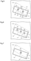
Fig. 7 is an enlarged plan view corresponding toFig. 5 , showing a core body placed on a jig plate according to a second modification. -
Fig. 8 is a vertical cross-sectional view corresponding toFig. 3 , showing, together with a rotor core, an apparatus for manufacturing a rotor core, the apparatus including a jig plate, according to a third modification. - Throughout the drawings and the detailed description, the same reference numerals refer to the same elements. The drawings may not be to scale, and the relative size, proportions, and depiction of elements in the drawings may be exaggerated for clarity, illustration, and convenience.
- This description provides a comprehensive understanding of the methods, apparatuses, and/or systems described. Modifications and equivalents of the methods, apparatuses, and/or systems described are apparent to one of ordinary skill in the art. Sequences of operations are exemplary, and may be changed as apparent to one of ordinary skill in the art, with the exception of operations necessarily occurring in a certain order. Descriptions of functions and constructions that are well known to one of ordinary skill in the art may be omitted.
- Exemplary embodiments may have different forms, and are not limited to the examples described. However, the examples described are thorough and complete, and convey the full scope of the disclosure to one of ordinary skill in the art.
- In this specification, "at least one of A and B" should be understood to mean "only A, only B, or both A and B."
- A jig plate designing method according to one embodiment will now be described with reference to
Figs. 1 to 5 . - First, a
rotor core 10 of an interior permanent magnet motor manufactured using a jig plate according to the present embodiment will be described with reference toFigs. 1 and 2 . - As shown in
Figs. 1 and 2 , therotor core 10 includes acore body 11, which includes a laminated body. The laminated body is formed by stackingcore sheets 12, which include magnetic steel sheets. Thecore body 11 is substantially shaped as a cylinder having an axis C. - In the following description, the radial direction of the
core body 11 will simply be referred to as a radial direction, and the circumferential direction of thecore body 11 will simply be referred to as a circumferential direction. - The
core body 11 includes acenter hole 11a andmagnet housing holes 13. Themagnet housing holes 13 are located on the radially outer side of thecenter hole 11a and arranged at intervals in the circumferential direction. Thecenter hole 11a and themagnet housing holes 13 extend through thecore body 11 in the axial direction (vertical direction inFigs. 1 and 2 ). - The
magnet housing holes 13 of the present embodiment each have a substantially rectangular shape in plan view and are inclined in relation to the circumferential direction. - As shown in
Fig. 1 , thecore body 11 includes twokey portions 11b on the inner circumferential surface of thecenter hole 11a to be opposed to each other in the radial direction of thecore body 11. - As shown in
Fig. 2 , eachmagnet housing hole 13 receives two rectangularparallelepiped magnets 14, which extend along the axis C of thecore body 11. - As indicated by the long-dash double-short-dash lines in
Fig. 5 , the twomagnets 14 are arranged adjacent to each other in the direction of the long sides of themagnet housing hole 13. Eachmagnet housing hole 13 is filled with aplastic 15 for fixing themagnet 14. The plastic 15 is preferably a thermosetting plastic such as an epoxy resin. - The
core body 11 of the present embodiment includes multiple blocks each includingcore sheets 12 stacked together. Thecore sheets 12 of each block include known joint portions (not shown), which are formed by the embossing technique to protrude from one side in the stacking direction (the axial direction). Thecore sheets 12 adjacent to each other are coupled together by press-fitting the protrusions of the coupling portions in one of thecore sheets 12 into the recesses of the coupling portions in theother core sheet 12. One end of each block includes adummy core sheet 12 having holes (not shown) formed by punching out the joint portions. Thedummy core sheet 12 is adjacent to acore sheet 12 in the same block and anothercore sheet 12 in a different block. Thedummy core sheet 12 is joined to thecore sheet 12 in the same block, but is not joined to thecore sheet 12 in the different block. Therefore, the blocks of thecore body 11 are separated from each other before the plastic 15 is provided in the magnet housing holes 13. - An apparatus for manufacturing the
rotor core 10 will now be described. - As shown in
Fig. 3 , the manufacturing apparatus includes ajig plate 20 and acull plate 40. - As shown in
Fig. 3 , thejig plate 20 includes aplate body 21, pins 26, and apost portion 30. - The
plate body 21 includes alower plate 22 and anupper plate 23, which is arranged on the upper surface of thelower plate 22. - The
post portion 30 is cylindrical and protrudes from a center part of thelower plate 22. Thepost portion 30 is inserted into thecenter hole 11a of thecore body 11. - The
post portion 30 includes twokeyways 31, which extend in the axial direction, on the outer circumferential surface. Thekey portions 11b of thecore body 11 are inserted into the keyways 31 (refer toFig. 4 ). When thekey portions 11b of thecore body 11 are inserted into thekeyways 31 of thepost portion 30, the phase of thecore body 11 with respect to thelower plate 22, more specifically, the phase of each block forming thecore body 11 is determined. - The
upper plate 23 includes a through-hole 24, which has a substantially circular shape in plan view centered on the axis C. - Two restricting projections (not shown) are provided on the inner circumferential surface of the through-
hole 24. The restricting projections are inserted into the twokeyways 31 of thepost portion 30 to position theupper plate 23 in relation to thelower plate 22. In a state in which thepost portion 30 is in the through-hole 24 of theupper plate 23, alower surface 11c of thecore body 11 is in contact with anupper surface 21c of theupper plate 23. - As shown in
Figs. 3 and4 , theupper plate 23 includes insertion holes 25 at positions overlapping with themagnet housing holes 13 in the axial direction. Two insertion holes 25 are provided for eachmagnet housing hole 13. Twopins 26 are inserted into and fixed to the twoinsertion holes 25 from below. - Each
pin 26 includes a protrudingportion 26a, which protrudes upward from theupper surface 21c of theupper plate 23. - The
jig plate 20 of the present embodiment can be used for two different types ofcore bodies magnet housing holes magnet housing holes - The
magnet housing holes - As shown in
Fig. 4 , themagnet housing holes 113 are shifted radially outward from the magnet housing holes 13. - As shown in
Figs. 4 and5 , themagnet housing holes core bodies magnet housing holes core bodies - Each region A has an elongated shape in plan view. A direction orthogonal to both the longitudinal direction of the region A and the axial direction in plan view is defined as a width direction.
- The two
pins 26, more specifically, the two protrudingportions 26a, are positioned in the region A. - The two
pins 26 are disposed at the center in the width direction of the region A. - A shown in
Fig. 3 , thecull plate 40 is placed on anupper surface 11d of thecore body 11. A lower surface 40a of thecull plate 40 is brought into contact with theupper surface 11d of thecore body 11. - The
cull plate 40 includes fillingports 41 for injecting the plastic 15 into themagnet housing holes 13 of thecore body 11 at intervals in the circumferential direction. Each fillingport 41 extends through thecull plate 40 in the thickness direction and is connected to two of the magnet housing holes 13. - In the present embodiment, the
upper surface 21c of theupper plate 23 corresponds to a placement surface of the present disclosure. Thekey portions 11b of thecore body 11 each correspond to an engaging portion of the present disclosure. Thekeyways 31 of thepost portion 30 each correspond to an engagement portion of the present disclosure. - Next, a procedure of fixing the
magnets 14 to thecore body 11 by using the manufacturing apparatus in which thejig plate 20 of the present embodiment is employed will be described. - First, the
core body 11 is placed on theupper surface 21c of theupper plate 23 of thejig plate 20, and then themagnets 14 are inserted into themagnet housing holes 13 of thecore body 11. At this time, thekey portions 11b are inserted into thekeyways 31. In eachmagnet housing hole 13, the lower surfaces of themagnets 14 are in contact with the protrudingportions 26a of thepins 26 above thelower surface 11c of thecore body 11. As a result, downward displacement of themagnet 14 is restricted, and themagnet 14 is positioned in the axial direction. - Next, the
cull plate 40 is placed on theupper surface 11d of thecore body 11 as shown inFig. 3 . - In this state, the plastic 15 is supplied to the filling
ports 41. The plastic 15 is injected into themagnet housing holes 13 of thecore body 11 through the fillingports 41. InFig. 3 , the plastic 15 is not shown. - Next, the entire manufacturing apparatus is heated by a heating device to thermally set the
thermosetting plastic 15, thereby fixing themagnets 14 to thecore body 11. - Operation of the present embodiment will now be described.
- As shown in
Fig. 5 , themagnets 14 housed in themagnet housing hole core body pins 26 corresponding to themagnets 14. Thus, thesame jig plate 20 can be used for thecore bodies - The present embodiment has the following advantages.
- (1) The
magnet housing holes core bodies magnet housing holes core bodies pins 26 are positioned in the regions A.
This method, which operates in the above described manner, allows the number of types of thejig plate 20 to be reduced. - (2) The
pins 26 are disposed at the center in the width direction of the region A. - If the
pins 26 were positioned closer to themagnet housing hole 13 of thefirst core body 11 in the width direction of the region A, thepins 26 would approach the center of the end faces of themagnets 14 housed in themagnet housing hole 13. On the other hand, thepins 26 would be separated from the center of themagnets 14 housed in themagnet housing hole 113 of thesecond core body 111. As a result, themagnet 14 housed in themagnet housing hole 113 of thesecond core body 111 may be supported in an unstable manner. - In this regard, the above-described method prevents the
magnet 14 from being supported in an unstable manner. - (3) The
jig plate 20 includes thepost portion 30, which protrudes from theplate body 21 and is inserted into thecenter hole 11a. Thepost portion 30 includes, in the outer circumferential surface, thekeyways 31, into which thekey portions 11b on the inner circumferential surface of thecenter hole 11a are inserted. - With this method, the
key portions 11b provided in thecenter hole 11a of thecore body 11 are engaged with thekeyways 31 provided in the outer peripheral surface of thepost portion 30, so that thecore body 11 is positioned in the circumferential direction of thepost portion 30. Accordingly, thecore body 11 is easily positioned with respect to thejig plate 20. - The above-described embodiment may be modified as follows. The above-described embodiment and the following modifications can be combined as long as the combined modifications remain technically consistent with each other.
- The
jig plate 20 may lack thepost portion 30. In this case, a post portion may be provided on a stationary base located below thejig plate 20, and a through-hole into which the post portion is inserted may be provided in the plate body. - In the above-described embodiment, the protruding
portions 26a of thepins 26 are arranged at the center of the region A in the width direction. However, the arrangement of the protrudingportions 26a may be changed within the region A. Even in this case, it suffices if themagnets 14 are positioned at specified positions in themagnet housing hole 13 by being supported from below. - The number of the
magnets 14 accommodated in eachmagnet housing hole 13 is not limited to two, but may be one or three. For example, when threemagnets 14 are housed in eachmagnet housing hole 13 as shown inFig. 6 , threepins 26 are provided in the region A so as to correspond to the threemagnets 14, respectively. - When two
magnets 14 are housed in eachmagnet housing hole 13 as shown inFig. 7 , asingle pin 26 may be provided at the border of the twomagnets 14. - The above-described embodiment illustrates the
jig plate 20 that can be used for two different types ofcore bodies magnet housing holes magnet housing holes - In the above-described embodiment, the
plate body 21 is formed by thelower plate 22 and theupper plate 23. However, thelower plate 22 may be omitted, and thepost portion 30 may be fixed to theupper plate 23. - In the above-described embodiment, the
plate body 21 and thepins 26 are separate components. However, the present disclosure is not limited thereto. As shown inFig. 8 , thepins 26 may be formed by protruding some parts of the upper surface of theplate body 21. - Various changes in form and details may be made to the examples above without departing from the spirit and scope of the claims and their equivalents. The examples are for the sake of description only, and not for purposes of limitation. Descriptions of features in each example are to be considered as being applicable to similar features or aspects in other examples. Suitable results may be achieved if sequences are performed in a different order, and/or if components in a described system, architecture, device, or circuit are combined differently, and/or replaced or supplemented by other components or their equivalents. The scope of the disclosure is not defined by the detailed description, but by the claims and their equivalents. All variations within the scope of the claims and their equivalents are included in the disclosure.
- A jig plate (20) includes a plate body (21) and pins (26). The plate body (21) includes an upper surface (21c) on which a core body (11) is placed. The core body (11) includes a center hole (11a) and magnet housing holes (13). The pins (26) protrude from the upper surface (21c) and come into contact with lower surfaces of magnets (14) housed in the magnet housing holes (13). The jig plate (20) can be used for a first core body (11) and a second core body, in which the numbers of the magnet housing holes are the same, but the positions of the magnet housing holes are different. The magnet housing holes of the core bodies of different types have regions (A) in which the magnet housing holes overlap with each other in an axial direction on the jig plate (20). The jig plate designing method includes positioning the pins (26) in the regions (A).
Claims (3)
- A jig plate designing method for designing a jig plate used for an apparatus for manufacturing a rotor core of an interior permanent magnet motor, whereinthe jig plate includes:a plate body including a placement surface on which a core body is placed, the core body including a center hole and magnet housing holes; andpins that protrude from the placement surface and come into contact with lower surfaces of magnets housed in the magnet housing holes,the jig plate is capable of being used for core bodies of different types that have a same number of the magnet housing holes, the core bodies of the different types having different shapes of the magnet housing holes and/or different positions of the magnet housing holes,the magnet housing holes of the core bodies of the different types have regions in which the magnet housing holes overlap with each other in an axial direction of the core bodies, andthe jig plate designing method comprises positioning the pins in the regions.
- The jig plate designing method according to claim 1, whereineach region has an elongated shape in plan view,a direction orthogonal to both a longitudinal direction of each region and the axial direction in plan view is defined as a width direction, andthe jig plate designing method comprises disposing each pin at a center in the width direction of a corresponding one of the regions.
- The jig plate designing method according to claim 1 or 2, whereinthe jig plate includes a post portion that protrudes from the plate body and is inserted into the center hole, andthe jig plate designing method further comprises providing, in an outer circumferential surface of the post portion, an engagement portion into which an engaging portion provided on an inner circumferential surface of the center hole is inserted.
Applications Claiming Priority (1)
| Application Number | Priority Date | Filing Date | Title |
|---|---|---|---|
| JP2021193310A JP7793957B2 (en) | 2021-11-29 | 2021-11-29 | How to design a jig plate |
Publications (1)
| Publication Number | Publication Date |
|---|---|
| EP4187762A1 true EP4187762A1 (en) | 2023-05-31 |
Family
ID=84361564
Family Applications (1)
| Application Number | Title | Priority Date | Filing Date |
|---|---|---|---|
| EP22209263.7A Pending EP4187762A1 (en) | 2021-11-29 | 2022-11-24 | Jig plate designing method |
Country Status (3)
| Country | Link |
|---|---|
| EP (1) | EP4187762A1 (en) |
| JP (1) | JP7793957B2 (en) |
| CN (1) | CN116191727A (en) |
Citations (2)
| Publication number | Priority date | Publication date | Assignee | Title |
|---|---|---|---|---|
| JP2019134566A (en) * | 2018-01-30 | 2019-08-08 | 本田技研工業株式会社 | Manufacturing method of rotor of rotary electric machine |
| JP2019140842A (en) | 2018-02-14 | 2019-08-22 | トヨタ紡織株式会社 | Rotor core manufacturing apparatus |
Family Cites Families (6)
| Publication number | Priority date | Publication date | Assignee | Title |
|---|---|---|---|---|
| JP2006166571A (en) | 2004-12-06 | 2006-06-22 | Toyota Motor Corp | Rotor structure of rotating electrical machine |
| JP5990886B2 (en) | 2011-09-22 | 2016-09-14 | 日産自動車株式会社 | Rotor |
| JP5996960B2 (en) | 2012-08-01 | 2016-09-21 | 株式会社三井ハイテック | Laminate core manufacturing equipment |
| JP6274096B2 (en) | 2014-09-17 | 2018-02-07 | トヨタ自動車株式会社 | Rotor core heating method and heating apparatus |
| JP6493257B2 (en) | 2016-03-10 | 2019-04-03 | アイシン・エィ・ダブリュ株式会社 | Manufacturing method of rotor |
| JP2019083653A (en) | 2017-10-31 | 2019-05-30 | トヨタ紡織株式会社 | Manufacturing apparatus of rotor core |
-
2021
- 2021-11-29 JP JP2021193310A patent/JP7793957B2/en active Active
-
2022
- 2022-11-24 EP EP22209263.7A patent/EP4187762A1/en active Pending
- 2022-11-24 CN CN202211485556.5A patent/CN116191727A/en active Pending
Patent Citations (2)
| Publication number | Priority date | Publication date | Assignee | Title |
|---|---|---|---|---|
| JP2019134566A (en) * | 2018-01-30 | 2019-08-08 | 本田技研工業株式会社 | Manufacturing method of rotor of rotary electric machine |
| JP2019140842A (en) | 2018-02-14 | 2019-08-22 | トヨタ紡織株式会社 | Rotor core manufacturing apparatus |
Also Published As
| Publication number | Publication date |
|---|---|
| JP2023079711A (en) | 2023-06-08 |
| JP7793957B2 (en) | 2026-01-06 |
| CN116191727A (en) | 2023-05-30 |
Similar Documents
| Publication | Publication Date | Title |
|---|---|---|
| CN101621221B (en) | Motor and method of manufacturing same | |
| JP6069250B2 (en) | Rotor manufacturing apparatus and rotor manufacturing method | |
| JP5382012B2 (en) | Rotor for rotating electrical machine and method for manufacturing the same | |
| CN111431306B (en) | Permanent magnet embedded rotor and method for manufacturing permanent magnet embedded rotor | |
| JP2009213349A (en) | Electric motor | |
| US11824405B2 (en) | Rotor of rotary electric machine | |
| JP4812787B2 (en) | Method of manufacturing rotor for pump motor, pump motor, pump and rotor for pump motor | |
| JP2019187165A (en) | Apparatus and method for manufacturing rotor core | |
| WO2016194598A1 (en) | Pump device | |
| JP2014003795A (en) | Rotor and manufacturing method for the same and permanent magnet motor | |
| CN109804533B (en) | Method for manufacturing rotor, and motor | |
| JP2018137867A (en) | Rotating electrical machine rotor and rotating electrical machine end face plate | |
| JP6028469B2 (en) | Resin molding method for mold and motor core | |
| US10476359B2 (en) | Motor rotor and method for manufacturing the same | |
| JP7442957B2 (en) | Rotor core manufacturing equipment | |
| JP4397598B2 (en) | stator | |
| JP2020099109A5 (en) | ||
| EP3223409A2 (en) | Orientation magnetization device and magnet-embedded rotor | |
| JP3796100B2 (en) | Linear motor | |
| JP2019083653A (en) | Manufacturing apparatus of rotor core | |
| JP2023079711A (en) | How to design a fixture plate | |
| JP6612713B2 (en) | Assembly method of magnetized yoke | |
| KR20070106925A (en) | Stepping motor | |
| US20240380292A1 (en) | Method for manufacturing rotor and rotor | |
| KR20220120845A (en) | split core of motor |
Legal Events
| Date | Code | Title | Description |
|---|---|---|---|
| PUAI | Public reference made under article 153(3) epc to a published international application that has entered the european phase |
Free format text: ORIGINAL CODE: 0009012 |
|
| STAA | Information on the status of an ep patent application or granted ep patent |
Free format text: STATUS: REQUEST FOR EXAMINATION WAS MADE |
|
| 17P | Request for examination filed |
Effective date: 20221124 |
|
| AK | Designated contracting states |
Kind code of ref document: A1 Designated state(s): AL AT BE BG CH CY CZ DE DK EE ES FI FR GB GR HR HU IE IS IT LI LT LU LV MC ME MK MT NL NO PL PT RO RS SE SI SK SM TR |
|
| STAA | Information on the status of an ep patent application or granted ep patent |
Free format text: STATUS: EXAMINATION IS IN PROGRESS |
|
| 17Q | First examination report despatched |
Effective date: 20260202 |