EP4187752A1 - Emergency call system and method for controlling operation of the same - Google Patents
Emergency call system and method for controlling operation of the same Download PDFInfo
- Publication number
- EP4187752A1 EP4187752A1 EP22210291.5A EP22210291A EP4187752A1 EP 4187752 A1 EP4187752 A1 EP 4187752A1 EP 22210291 A EP22210291 A EP 22210291A EP 4187752 A1 EP4187752 A1 EP 4187752A1
- Authority
- EP
- European Patent Office
- Prior art keywords
- battery
- parallel connection
- call
- switch
- bank
- Prior art date
- Legal status (The legal status is an assumption and is not a legal conclusion. Google has not performed a legal analysis and makes no representation as to the accuracy of the status listed.)
- Granted
Links
Images


Classifications
-
- H—ELECTRICITY
- H02—GENERATION; CONVERSION OR DISTRIBUTION OF ELECTRIC POWER
- H02J—ELECTRIC POWER NETWORKS; CIRCUIT ARRANGEMENTS OR SYSTEMS FOR SUPPLYING OR DISTRIBUTING ELECTRIC POWER; SYSTEMS FOR STORING ELECTRIC ENERGY
- H02J7/00—Circuit arrangements for charging or discharging batteries or for supplying loads from batteries
- H02J7/50—Circuit arrangements for charging or discharging batteries or for supplying loads from batteries acting upon multiple batteries simultaneously or sequentially
- H02J7/585—Sequential battery discharge in systems with a plurality of batteries
-
- H—ELECTRICITY
- H02—GENERATION; CONVERSION OR DISTRIBUTION OF ELECTRIC POWER
- H02J—ELECTRIC POWER NETWORKS; CIRCUIT ARRANGEMENTS OR SYSTEMS FOR SUPPLYING OR DISTRIBUTING ELECTRIC POWER; SYSTEMS FOR STORING ELECTRIC ENERGY
- H02J7/00—Circuit arrangements for charging or discharging batteries or for supplying loads from batteries
- H02J7/50—Circuit arrangements for charging or discharging batteries or for supplying loads from batteries acting upon multiple batteries simultaneously or sequentially
- H02J7/575—Parallel/serial switching of connection of batteries to charge or load circuit
-
- G—PHYSICS
- G08—SIGNALLING
- G08B—SIGNALLING SYSTEMS, e.g. PERSONAL CALLING SYSTEMS; ORDER TELEGRAPHS; ALARM SYSTEMS
- G08B29/00—Checking or monitoring of signalling or alarm systems; Prevention or correction of operating errors, e.g. preventing unauthorised operation
- G08B29/18—Prevention or correction of operating errors
- G08B29/181—Prevention or correction of operating errors due to failing power supply
-
- H—ELECTRICITY
- H01—ELECTRIC ELEMENTS
- H01M—PROCESSES OR MEANS, e.g. BATTERIES, FOR THE DIRECT CONVERSION OF CHEMICAL ENERGY INTO ELECTRICAL ENERGY
- H01M10/00—Secondary cells; Manufacture thereof
- H01M10/42—Methods or arrangements for servicing or maintenance of secondary cells or secondary half-cells
- H01M10/425—Structural combination with electronic components, e.g. electronic circuits integrated to the outside of the casing
- H01M10/4257—Smart batteries, e.g. electronic circuits inside the housing of the cells or batteries
-
- H—ELECTRICITY
- H01—ELECTRIC ELEMENTS
- H01M—PROCESSES OR MEANS, e.g. BATTERIES, FOR THE DIRECT CONVERSION OF CHEMICAL ENERGY INTO ELECTRICAL ENERGY
- H01M10/00—Secondary cells; Manufacture thereof
- H01M10/42—Methods or arrangements for servicing or maintenance of secondary cells or secondary half-cells
- H01M10/44—Methods for charging or discharging
- H01M10/443—Methods for charging or discharging in response to temperature
-
- H—ELECTRICITY
- H02—GENERATION; CONVERSION OR DISTRIBUTION OF ELECTRIC POWER
- H02J—ELECTRIC POWER NETWORKS; CIRCUIT ARRANGEMENTS OR SYSTEMS FOR SUPPLYING OR DISTRIBUTING ELECTRIC POWER; SYSTEMS FOR STORING ELECTRIC ENERGY
- H02J7/00—Circuit arrangements for charging or discharging batteries or for supplying loads from batteries
- H02J7/34—Parallel operation in networks using both storage and other DC sources, e.g. providing buffering
- H02J7/342—The other DC source being a battery actively interacting with the first one, i.e. battery to battery charging
-
- H—ELECTRICITY
- H02—GENERATION; CONVERSION OR DISTRIBUTION OF ELECTRIC POWER
- H02J—ELECTRIC POWER NETWORKS; CIRCUIT ARRANGEMENTS OR SYSTEMS FOR SUPPLYING OR DISTRIBUTING ELECTRIC POWER; SYSTEMS FOR STORING ELECTRIC ENERGY
- H02J7/00—Circuit arrangements for charging or discharging batteries or for supplying loads from batteries
- H02J7/40—Circuit arrangements for charging or discharging batteries or for supplying loads from batteries characterised by the exchange of charge or discharge related data
-
- H—ELECTRICITY
- H02—GENERATION; CONVERSION OR DISTRIBUTION OF ELECTRIC POWER
- H02J—ELECTRIC POWER NETWORKS; CIRCUIT ARRANGEMENTS OR SYSTEMS FOR SUPPLYING OR DISTRIBUTING ELECTRIC POWER; SYSTEMS FOR STORING ELECTRIC ENERGY
- H02J7/00—Circuit arrangements for charging or discharging batteries or for supplying loads from batteries
- H02J7/60—Circuit arrangements for charging or discharging batteries or for supplying loads from batteries including safety or protection arrangements
-
- H—ELECTRICITY
- H02—GENERATION; CONVERSION OR DISTRIBUTION OF ELECTRIC POWER
- H02J—ELECTRIC POWER NETWORKS; CIRCUIT ARRANGEMENTS OR SYSTEMS FOR SUPPLYING OR DISTRIBUTING ELECTRIC POWER; SYSTEMS FOR STORING ELECTRIC ENERGY
- H02J7/00—Circuit arrangements for charging or discharging batteries or for supplying loads from batteries
- H02J7/80—Circuit arrangements for charging or discharging batteries or for supplying loads from batteries including monitoring or indicating arrangements
-
- H—ELECTRICITY
- H02—GENERATION; CONVERSION OR DISTRIBUTION OF ELECTRIC POWER
- H02J—ELECTRIC POWER NETWORKS; CIRCUIT ARRANGEMENTS OR SYSTEMS FOR SUPPLYING OR DISTRIBUTING ELECTRIC POWER; SYSTEMS FOR STORING ELECTRIC ENERGY
- H02J7/00—Circuit arrangements for charging or discharging batteries or for supplying loads from batteries
- H02J7/855—Circuit arrangements for charging or discharging batteries or for supplying loads from batteries with circuits adapted for supplying loads from the battery
-
- H—ELECTRICITY
- H02—GENERATION; CONVERSION OR DISTRIBUTION OF ELECTRIC POWER
- H02J—ELECTRIC POWER NETWORKS; CIRCUIT ARRANGEMENTS OR SYSTEMS FOR SUPPLYING OR DISTRIBUTING ELECTRIC POWER; SYSTEMS FOR STORING ELECTRIC ENERGY
- H02J7/00—Circuit arrangements for charging or discharging batteries or for supplying loads from batteries
- H02J7/90—Regulation of charging or discharging current or voltage
- H02J7/971—Regulation of charging or discharging current or voltage the charge cycle being controlled or terminated in response to non-electric parameters
- H02J7/975—Regulation of charging or discharging current or voltage the charge cycle being controlled or terminated in response to non-electric parameters in response to temperature
-
- H—ELECTRICITY
- H02—GENERATION; CONVERSION OR DISTRIBUTION OF ELECTRIC POWER
- H02J—ELECTRIC POWER NETWORKS; CIRCUIT ARRANGEMENTS OR SYSTEMS FOR SUPPLYING OR DISTRIBUTING ELECTRIC POWER; SYSTEMS FOR STORING ELECTRIC ENERGY
- H02J9/00—Circuit arrangements for emergency or stand-by power supply, e.g. for emergency lighting
- H02J9/04—Circuit arrangements for emergency or stand-by power supply, e.g. for emergency lighting in which the distribution system is disconnected from the normal source and connected to a standby source
- H02J9/06—Circuit arrangements for emergency or stand-by power supply, e.g. for emergency lighting in which the distribution system is disconnected from the normal source and connected to a standby source with automatic change-over, e.g. UPS systems
- H02J9/061—Circuit arrangements for emergency or stand-by power supply, e.g. for emergency lighting in which the distribution system is disconnected from the normal source and connected to a standby source with automatic change-over, e.g. UPS systems for DC powered loads
-
- G—PHYSICS
- G08—SIGNALLING
- G08B—SIGNALLING SYSTEMS, e.g. PERSONAL CALLING SYSTEMS; ORDER TELEGRAPHS; ALARM SYSTEMS
- G08B25/00—Alarm systems in which the location of the alarm condition is signalled to a central station, e.g. fire or police telegraphic systems
- G08B25/01—Alarm systems in which the location of the alarm condition is signalled to a central station, e.g. fire or police telegraphic systems characterised by the transmission medium
- G08B25/016—Personal emergency signalling and security systems
-
- H—ELECTRICITY
- H01—ELECTRIC ELEMENTS
- H01M—PROCESSES OR MEANS, e.g. BATTERIES, FOR THE DIRECT CONVERSION OF CHEMICAL ENERGY INTO ELECTRICAL ENERGY
- H01M10/00—Secondary cells; Manufacture thereof
- H01M10/42—Methods or arrangements for servicing or maintenance of secondary cells or secondary half-cells
- H01M10/425—Structural combination with electronic components, e.g. electronic circuits integrated to the outside of the casing
- H01M2010/4271—Battery management systems including electronic circuits, e.g. control of current or voltage to keep battery in healthy state, cell balancing
-
- H—ELECTRICITY
- H01—ELECTRIC ELEMENTS
- H01M—PROCESSES OR MEANS, e.g. BATTERIES, FOR THE DIRECT CONVERSION OF CHEMICAL ENERGY INTO ELECTRICAL ENERGY
- H01M10/00—Secondary cells; Manufacture thereof
- H01M10/42—Methods or arrangements for servicing or maintenance of secondary cells or secondary half-cells
- H01M10/425—Structural combination with electronic components, e.g. electronic circuits integrated to the outside of the casing
- H01M2010/4278—Systems for data transfer from batteries, e.g. transfer of battery parameters to a controller, data transferred between battery controller and main controller
-
- H—ELECTRICITY
- H02—GENERATION; CONVERSION OR DISTRIBUTION OF ELECTRIC POWER
- H02J—ELECTRIC POWER NETWORKS; CIRCUIT ARRANGEMENTS OR SYSTEMS FOR SUPPLYING OR DISTRIBUTING ELECTRIC POWER; SYSTEMS FOR STORING ELECTRIC ENERGY
- H02J7/00—Circuit arrangements for charging or discharging batteries or for supplying loads from batteries
- H02J7/80—Circuit arrangements for charging or discharging batteries or for supplying loads from batteries including monitoring or indicating arrangements
- H02J7/82—Control of state of charge [SOC]
-
- H—ELECTRICITY
- H02—GENERATION; CONVERSION OR DISTRIBUTION OF ELECTRIC POWER
- H02J—ELECTRIC POWER NETWORKS; CIRCUIT ARRANGEMENTS OR SYSTEMS FOR SUPPLYING OR DISTRIBUTING ELECTRIC POWER; SYSTEMS FOR STORING ELECTRIC ENERGY
- H02J7/00—Circuit arrangements for charging or discharging batteries or for supplying loads from batteries
- H02J7/80—Circuit arrangements for charging or discharging batteries or for supplying loads from batteries including monitoring or indicating arrangements
- H02J7/84—Control of state of health [SOH]
-
- Y—GENERAL TAGGING OF NEW TECHNOLOGICAL DEVELOPMENTS; GENERAL TAGGING OF CROSS-SECTIONAL TECHNOLOGIES SPANNING OVER SEVERAL SECTIONS OF THE IPC; TECHNICAL SUBJECTS COVERED BY FORMER USPC CROSS-REFERENCE ART COLLECTIONS [XRACs] AND DIGESTS
- Y02—TECHNOLOGIES OR APPLICATIONS FOR MITIGATION OR ADAPTATION AGAINST CLIMATE CHANGE
- Y02E—REDUCTION OF GREENHOUSE GAS [GHG] EMISSIONS, RELATED TO ENERGY GENERATION, TRANSMISSION OR DISTRIBUTION
- Y02E60/00—Enabling technologies; Technologies with a potential or indirect contribution to GHG emissions mitigation
- Y02E60/10—Energy storage using batteries
Definitions
- the present disclosure relates to an emergency call (E-call) system and a method for controlling an operation of the same, and more particularly, to an E-call system configured to improve discharge performance of an E-call battery in a low-temperature environment and a method for controlling an operation of the same.
- E-call emergency call
- An emergency call system (hereinafter referred to as an "E-call system”) is being developed that automatically makes an emergency call at a time point of a car accident, or allows an occupant to make a direct call to report an accident and request rescue in case of an emergency situation.
- the system may be applied as part of an infotainment system of a vehicle, or separately as a telematics system of the vehicle.
- Such an emergency call system may be applied as an emergency communication system in a mobile communication system such as a mobile phone as well as a vehicle.
- the emergency call system or E-call system refers to an emergency communication system mounted on a mobile communication device as well as a vehicle.
- the E-call systems are operated by batteries that are mounted on automobiles and supply electric power to various electronic devices.
- electric power supply to the E-call system is not smooth due to a battery failure that occurs in a vehicle accident.
- a separate spare battery for the E-call system hereinafter referred to as an "E-call battery" is used.
- the operating temperature/environmental conditions are harsh and the warranty period is long.
- an internal resistance of a battery cell increases, resulting in a sudden voltage drop in the initial stage of discharging.
- the increase in the internal resistance of the battery cell at a very low temperature is a phenomenon that occurs as the electrochemical reaction inside the cell is lowered, such as the freezing of the electrolyte.
- Patent Document 1 the low-temperature driving problem is solved by raising the temperature of the battery by generating heat through low current discharge at a low temperature
- Patent Document 2 the low-temperature voltage drop problem is solved by increasing the cell voltage by connecting separate cells in series at a low temperature.
- Patent Document 1 the battery is used after the temperature is raised through heat by a separate resistor, and thus, it takes time for the battery to heat up and return to the normal temperature, and in some external situations, it is difficult for the battery to return to the normal temperature.
- Patent Document 2 a method is used in which a total cell voltage is increased by connecting additional battery cells in series to suppress a voltage drop caused by an increase in internal resistance due to a low temperature, but in the method, a difference between the voltage drop amount and the additional cell voltage occurs, the output voltage becomes higher than necessary when the additional cell is connected, and so on, which may lead to problems.
- the present disclosure has been made in consideration of the aforementioned circumstances, and provides a battery system for E-call including an auxiliary device for preventing a sudden voltage drop due to a very low temperature in a battery for E-call and a method for controlling an operation of the same.
- an emergency call (E-call) system including: an E-call battery including first and second battery cells arranged in parallel; a parallel connection switch configured to control an electrical parallel connection between the first and second battery cells of the E-call battery; a temperature data acquisition controller configured to acquire battery usage environment temperature data from an external system connected to the E-call battery at regular intervals; a comparison controller configured to compare a battery usage environment temperature value acquired by the temperature data acquisition controller with a predetermined reference temperature; and a switch controller configured to control on/off of the parallel connection switch according to a comparison result of the comparison controller.
- the system may start operation as the parallel connection switch is initially in an off state.
- the comparison controller may output a low-temperature signal when the acquired battery usage environment temperature is less than the predetermined reference temperature, and may output a normal-temperature signal when the acquired battery usage environment temperature is equal to or higher than the predetermined reference temperature.
- the switch control unit may output a turn-on signal to the parallel connection switch when the low-temperature signal is output from the comparison controller, and may output a turn-off signal to the parallel connection switch when the normal-temperature signal is output from the comparison controller.
- the predetermined reference temperature may be set in advance based on a system requirement, and in an exemplary embodiment, may be set to 0 degrees Celsius.
- the E-call battery may be driven in a 1 series 2 parallel (1S2P) mode in which the first battery cell and the second battery cell are connected in parallel, when the parallel connection switch is turned on by the switch control unit, and may be driven in a 1 series 1 parallel (1S1P) mode in which parallel connection of the first battery cell and the second battery cell is released, when the parallel connection switch is turned off by the switch control unit.
- 1S2P 1 series 2 parallel
- (1S1P) mode in which parallel connection of the first battery cell and the second battery cell is released, when the parallel connection switch is turned off by the switch control unit.
- the E-call battery may include: a first output path that connects an output of the first battery bank to a (+) output terminal of the E-call battery; a second output path that connects an output of the second battery bank to a (+) output terminal of the E-call battery; a parallel connection path that connects the first output path and the second output path in parallel to form an electrical parallel connection between the first battery bank and the second battery bank; and a parallel connection switch disposed on the parallel connection path to open or close the parallel connection path, and the E-call battery may be driven in a 1S2P mode in which the first battery bank and the second battery bank are connected in parallel, when the parallel connection switch is turned on by the switch control unit and may be driven in a IS IP mode in which parallel connection of the first battery bank and the second battery bank is released and just an output of one of the first battery bank and the second battery bank is connected to the (+) output terminal of the E-call battery, when the parallel connection switch is turned off by the switch control unit.
- the switch control unit may control on/ off of the parallel connection switch, and may control both the first discharge control switch and the second discharge control switch to be on when the parallel connection switch is controlled to be on and may control just one of the first discharge control switch and the second discharge control switch to be on when the parallel connection switch is controlled to be off.
- a method for controlling an operation of an E-call battery including first and second battery cells arranged in parallel, the method including: acquiring temperature data by acquiring battery usage environment temperature data from an external system connected to the E-call battery at regular intervals; comparing a battery usage environment temperature acquired in the acquiring of the temperature data with a predetermined reference temperature to check whether the battery usage environment temperature is less than or higher than the reference temperature; controlling a parallel connection switch to be on/off according to a comparison result in the comparing with the reference temperature, the parallel connection switch being configured to control an electrical parallel connection between the first and second battery cells; and discharging the E-call battery with an electric connection structure corresponding to the control of the parallel connection switch in the controlling of the parallel connection switch.
- the controlling of the parallel connection switch may include turning on the parallel connection switch when the acquired battery usage environment temperature is less than the predetermined reference temperature as the comparison result, and turning off the parallel connection switch when the acquired battery usage environment temperature is equal to or higher than the predetermined reference temperature as the comparison result.
- the E-call battery may be operated in a 1S2P mode in which the first and second battery cells are connected in parallel when the parallel connection switch is turned on in the controlling of the parallel connection switch, and the E-call battery may be operated in a IS IP mode in which parallel connection of the first battery cell and the second battery cell is released when the parallel connection switch is turned off in the controlling of the parallel connection switch.
- the predetermined reference temperature may be 0 degrees Celsius.
- the performing of the IS IP mode driving control may include performing output of a main use bank by selecting the main use bank out of the first and second battery banks and controlling a discharge control switch of the main use bank to be on, and the performing of the output of the main use bank may include: determining a bank use state by calculating at least one of an accumulated use time or a state of charge (SOC) or state of health (SOH) of the first battery bank or the second battery bank; and selecting the main use bank according to the at least one of the accumulated use time or the SOC or SOH of the first battery bank or the second battery bank which is calculated in the determining of the bank use state.
- SOC state of charge
- SOH state of health
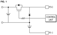
- FIG. 1 is a diagram schematically illustrating the related art.
- a controller e.g., a temperature data acquisition controller, a switch controller or a comparison controller
- processors e.g., microprocessors or microcontrollers
- FIGS. 2(a) and 2(b) are diagram schematically illustrating an emergency call (E-call) system in accordance with an exemplary embodiment.
- the E-call systems of exemplary embodiments may include the following configurations.
- a battery 100 for E-call (E-call battery 100) of an exemplary embodiment has a structure in which two battery banks 100a and 100b are arranged in parallel.
- the first and second battery banks 100a and 100b constituting the E-call battery 100 have a structure arranged in parallel, and mutual electrical parallel connection therebetween is limited according to the on/off operation of a parallel connection switch 200 to be described later.
- the E-call battery 100 may be initially driven in a 1 Series 1 Parallel (1S1P) mode in which the first and second battery banks 100a and 100b are not electrically connected in parallel, and thereafter, may be driven in the 1S1P mode or a 1 Series 2 Parallel (1S2P) mode according to the on/off of the parallel connection switch 200 to be described later.
- 1S1P 1 Series 1 Parallel
- 1S2P 1 Series 2 Parallel
- the IS IP mode is a mode in which the parallel connection switch 200 is turned off to open a parallel connection path of the two battery banks 100a and 100b, and the voltage of one battery bank is output. As shown in FIG. 2(a) , the output of the first battery bank 100a is connected to an output terminal through a resistor R.
- the 1S2P mode is a mode in which the parallel connection switch 200 is turned on and the two battery banks 100a and 100b are connected in parallel to output a parallel voltage.
- the parallel connection switch 200 is configured to control the connecting or opening of an electrical parallel connection path between the first and second battery banks 100a and 100b constituting the E-call battery 100.
- the parallel connection switch 200 may be controlled to be on or off by the control of a switch controller 500 to be described later such that the E-call battery 100 is driven in the 1S2P mode or is driven in the 1S1P mode.
- the parallel connection switch 200 is to function as an auxiliary device for preventing a phenomenon that the voltage suddenly drops in the E-call battery 100 due to the very low temperature.
- FET filed-effect transistor
- a temperature data acquisition controller 300 is configured to acquire battery usage environment temperature data from an external system (not shown) connected to the E-call battery 100 at regular intervals.
- the external system may be a communication device of an electric vehicle or a small mobile device, or a single mobile communication device.
- a comparison controller 400 is configured to perform comparison to check whether a battery usage environment temperature value T acquired by the temperature data acquisition controller 300 is equal to or higher than or less than a predetermined reference temperature.
- the predetermined reference temperature value may be 0 degrees Celsius.
- the comparison controller 400 performs the comparison to check whether the battery usage environment temperature is less than or equal to or higher than 0 degrees Celsius.
- a low-temperature signal indicating the fact may be output.
- a normal-temperature signal indicating the fact may be output.
- the switch control unit 500 is configured to control on/off of the parallel connection switch 200 according to the comparison result of the comparison controller 400.
- the parallel connection switch 200 may be turned on.
- the switch control unit 500 may output a turn-on signal to the parallel connection switch 200 to connect the parallel connection path between the first and second battery banks 100a and 100b and drive the E-call battery 100 in the 1S2P mode.
- the parallel connection switch 200 may implement its turn-on by receiving a voltage of approximately 3.3 V applied from an external control power supply (not shown), for example, a 12V auxiliary battery (not shown).
- the parallel connection switch 200 may be turned off.
- the switch control unit 500 may output a turn-off signal to the parallel connection switch 200 to open the parallel connection path between the first and second battery banks 100a and 100b and drive the E-call battery 100 in the 1S1P mode.
- the parallel connection switch 200 may implement its turn- off by receiving a voltage of 0 V applied.
- the switch control unit 500 controls on/off of a first discharge control switch 110a and a second discharge control switch 110b, as well as the parallel connection switch 200. On/off control algorithm of each switch will be described later.
- the temperature data acquisition controller 300, the comparison controller 400, and the switch control unit 500 may be included as one configuration of a battery management system.
- a battery pack is provided in which a first discharge control switch 110a and a second discharge control switch 110b are disposed between the first and second battery banks 100a and 100b and the output terminal instead of the resistor R.
- one of the first and second battery banks 100a and 100b is selectively connected to the output terminal. That is, in the present exemplary embodiment, one of the first and second battery banks may be selectively used for external output depending on the remaining amounts of the first and second batteries, and the other one may be used for coping with a low-temperature voltage drop. In this case, it is desirable to set both the first and second battery banks 100a and 100b to satisfy an output voltage/current requirement of an output cell.
- FIG. 3 is a flowchart illustrating a method for controlling an operation of the E-call battery in accordance with an exemplary embodiment.
- the method according to the present exemplary embodiment may include the following steps.
- a temperature data acquisition step S100 is a step of acquiring battery usage environment temperature data from an external system (not shown) connected to the E-call battery 100 having a 1S2P structure at regular intervals.
- the external system may be a vehicle.
- a reference temperature comparison step S200 is a step of comparing a battery usage environment temperature acquired in the temperature data acquisition step S100 with a predetermined reference temperature to check whether the battery usage environment temperature is less than or equal to or higher than the reference temperature.
- the predetermined reference temperature may be 0 degrees Celsius.
- comparison is performed to check whether the acquired battery usage environment temperature is less than or higher than the reference temperature of 0 degrees Celsius.
- a switch control step S300 is a step of controlling on/off of the parallel connection switch 200 that controls electrical parallel connection between the first and second battery banks 100a and 100b constituting the E-call battery 100 of the 1S2P structure according to the result of comparison in the reference temperature comparison step S200.
- the parallel connection switch 200 may be turned on (S310).
- the parallel connection switch 200 may be turned off (S320).
- the parallel connection switch 200 is initially set to the turn-off state, and the electrical parallel connection between the first and second battery banks 100a and 100b of the E-call battery 100 are cut off and the operation in the 1S1P mode is performed.
- a battery discharging operation step S400 is a step of discharging the E-call battery 100 with an electric connection structure corresponding to the control operation of the parallel connection switch 200 in the switch control step S300.
- the parallel connection switch 200 when the parallel connection switch 200 is turned on in the switch control step S300 (S310), the first and second battery banks 100a and 100b of the E-call battery 100 are electrically connected in parallel to each other and are operated in the 1S2P mode (S410).
- one of the first and second battery banks 100a and 100b may be selected as a use bank, that is, a battery bank for output by controlling the first and second discharge control switches.
- the selection of the battery bank for output may be made according to an accumulated use time or a state of charge (SOC) or state of health (SOH) of the battery banks, and in this case, the switch control unit transmits a switching control signal to the battery banks.
- SOC state of charge
- SOH state of health
- the cell for coping with voltage drop is able to be interchangeably used as the output cell as compared to using only one of the first and second battery banks as the output cell.
- FIG. 4 An operation procedure of the battery in accordance with the exemplary embodiment shown in FIG. 2(b) will be described with reference to FIG. 4 .
- the same reference numerals are used for the same parts as in the procedure of FIG. 3 .
- a temperature data acquisition step S100 is a step of acquiring battery usage environment temperature data from an external system (not shown) connected to the E-call battery 100 having a 1S2P structure at regular intervals.
- the external system may be a communication system of a vehicle or a small mobile device, or an independent mobile communication device.
- a reference temperature comparison step S200 is a step of comparing a battery usage environment temperature acquired in the temperature data acquisition step S100 with a predetermined reference temperature to check whether the battery usage environment temperature is less than or equal to or higher than the reference temperature.
- the predetermined reference temperature may be 0 degrees Celsius.
- comparison is performed to check whether the acquired battery usage environment temperature is less than or higher than a predetermined reference temperature, for example, 0 degrees Celsius.
- a switch control step S300 is a step of controlling on/off of the parallel connection switch 200 that controls electrical parallel connection between the first and second battery banks 100a and 100b constituting the E-call battery 100 of the 1S2P structure according to the result of comparison in the reference temperature comparison step S200.
- the parallel connection switch 200 (Q1) may be turned on (S310).
- the first and second discharge control switches 110a and 110b (Q2, Q3) are also turned on, so that the first and second battery banks 100a and 100b may be connected in parallel, and may be driven in the 1S2P mode in a battery discharging operation step to be described later.
- the driving of the battery in the 1S2P mode may be started according to a predetermined E-call mode operation control signal.
- 1S2P mode driving is performed to improve the low-temperature discharge performance.
- the parallel connection switch 200 may be turned off to prepare the IS IP mode driving (S320).
- the parallel connection switch 200 is set to the turn-off state, and the electrical parallel connection between the first and second battery banks 100a and 100b of the E-call battery 100 are cut off and the operation in the 1S1P mode is performed in the battery discharging operation step S400 to be described later.
- a battery discharging operation step S400 is a step of discharging the E-call battery 100 with an electric connection structure corresponding to the control operation of the parallel connection switch 200 in the switch control step S300.
- the parallel connection switch 200 when the parallel connection switch 200 is turned on in the switch control step S300 (S310), the first and second battery banks 100a and 100b of the E-call battery 100 are electrically connected in parallel to each other and are operated in the 1S2P mode during the E-call mode (S410).
- the mode is not the E-call mode, that is, when the E-call mode operation signal is not received, the process returns to step S100.
- the parallel connection switch 200 When the parallel connection switch 200 is turned off in the switch control step S300 (S320), the electrical parallel connection between the first and second battery banks 100a and 100b of the E-call battery 100 are cut off, and the operation in the IS IP mode is performed during operating in the E-call mode (S420).
- the mode is not the E-call mode, that is, when the E-call mode operation signal is not received, the process returns to step S100.
- a process of deciding which of the first and second battery banks is to be used as the main bank is performed.
- the parallel connection switch 200 (Q1) is turned off, and each of the output terminals the first and second battery banks outputs or blocks the bank voltage to the output terminal P(+) according to the on/off control of the first and second discharge control switches 110a and 110b (Q2 and Q3).
- a main use bank output procedure of selecting one of the first and second battery banks 100a and 100b and outputting the voltage of the selected battery bank to the output terminal P(+) is performed, and for selection of the main use bank, the switch control unit 500 may select the main use battery through a bank use state determination step (S421), a use bank maintenance step (S422), and a use bank replacement step (S423).
- the discharge control switch on the side of the bank determined as the main use bank is turned on so that only the corresponding bank is connected to the output terminal.
- the main use bank selection step may be implemented through the following procedure.
- the on/off state of the switches Q2 and Q3 may be determined so that only one battery bank is a main bank connected to an output terminal, and in this case, a determination is made as to whether the accumulated use time of the main bank exceeds a predetermined reference use time.
- the state of charge (SOC) or state of health (SOH) of each battery bank may be calculated, and the use state may be determined by determining whether the calculated value is less than a predetermined reference value.
- the main use bank may be maintained or selected through additional procedures to be described below, based on at least one calculated value of the accumulated use time or the SOC or SOH of the first or second battery bank, which are calculated according to the bank use state determination.
- the main bank discharge control switch on the side of the main bank is controlled to be on, and the discharge control switch on the other bank side is controlled to be off.
- the main bank discharge control switch is in the on state, and thus the first and second discharge control switches are maintained without the switching operation.
- the charging capacity of the main bank is equal to or greater than a predetermined reference value
- the use of the corresponding bank may be maintained. Even in this case, the switching operation of the first and second discharge control switches is not performed.
- the use bank When the main bank is determined, and when the accumulated use time of the main bank is greater than the predetermined reference time, the use bank is replaced. Alternatively, when the charging capacity of the main bank is less than the predetermined reference value, the use bank is replaced.
- the replacement of the use bank is achieved by switching the first and second discharge control switches from on to off or from off to on. In any case, in the 1S1P mode, the parallel connection switch 200 is controlled to be off, and the first and second discharge control switches 110a and 110b are selectively controlled such that one is on and the other is off.
- a bank to be used may be selected according to the control of the switch control unit 500.
- a bank to be used is selected according to the accumulated use time of each battery bank, and the SOC and the SOH of each battery bank acquired in the bank use state determination step S421 above.
- a criterion for selecting the bank to be used may be to select the one with the smaller accumulated use time or the one with the larger SOC or SOH, between the two battery banks.
- the battery bank connected in parallel and used to prevent voltage drop may be used in the 1S1P mode, thereby increasing the operating life of the E-call battery system.
- a battery bank may be a battery module of a single battery cell or of an aggregate of a plurality of battery cells, or a battery pack that is an aggregate of a plurality of battery modules.
- a battery management system for controlling the first and second battery banks may be provided, and the temperature data acquisition controller 300, the comparison controller 400, and the switch control unit 500 may be included in the BMS.
Landscapes
- Engineering & Computer Science (AREA)
- Power Engineering (AREA)
- Manufacturing & Machinery (AREA)
- General Chemical & Material Sciences (AREA)
- Electrochemistry (AREA)
- Chemical Kinetics & Catalysis (AREA)
- Chemical & Material Sciences (AREA)
- Emergency Management (AREA)
- Microelectronics & Electronic Packaging (AREA)
- General Physics & Mathematics (AREA)
- Physics & Mathematics (AREA)
- Computer Security & Cryptography (AREA)
- Business, Economics & Management (AREA)
- Secondary Cells (AREA)
- Charge And Discharge Circuits For Batteries Or The Like (AREA)
Abstract
Description
- This application claims priority to
Korean Patent Application No. 10-2021-0168988 filed on 11, 30, 2021 10-2022-0137219 filed on 10. 24. 2022 - The present disclosure relates to an emergency call (E-call) system and a method for controlling an operation of the same, and more particularly, to an E-call system configured to improve discharge performance of an E-call battery in a low-temperature environment and a method for controlling an operation of the same.
- An emergency call system (hereinafter referred to as an "E-call system") is being developed that automatically makes an emergency call at a time point of a car accident, or allows an occupant to make a direct call to report an accident and request rescue in case of an emergency situation. The system may be applied as part of an infotainment system of a vehicle, or separately as a telematics system of the vehicle. Such an emergency call system may be applied as an emergency communication system in a mobile communication system such as a mobile phone as well as a vehicle.
- As such, in the present disclosure, the emergency call system or E-call system refers to an emergency communication system mounted on a mobile communication device as well as a vehicle.
- The E-call systems are operated by batteries that are mounted on automobiles and supply electric power to various electronic devices. Here, there may be a situation in which electric power supply to the E-call system is not smooth due to a battery failure that occurs in a vehicle accident. In preparation for the above-mentioned situation, a separate spare battery for the E-call system (hereinafter referred to as an "E-call battery") is used.
- Meanwhile, in the case of an E-call battery applied to an automobile, the operating temperature/environmental conditions are harsh and the warranty period is long. In particular, in a very-low-temperature environment, an internal resistance of a battery cell increases, resulting in a sudden voltage drop in the initial stage of discharging. Here, the increase in the internal resistance of the battery cell at a very low temperature is a phenomenon that occurs as the electrochemical reaction inside the cell is lowered, such as the freezing of the electrolyte.
- Due to the increase, when the voltage falls below the minimum voltage that has to be supplied to the system connected to the E-call battery, normal operation may be impossible, which may result in the problem that performance implementation is impossible.
- However, in the case of the existing E-call battery, a separate auxiliary device/means for preventing a sudden voltage drop caused by the very low temperature is not provided, and as a consequence, a situation arises in which the performance of the battery cell has to be relied upon.
- In this regard, in Patent Document 1, the low-temperature driving problem is solved by raising the temperature of the battery by generating heat through low current discharge at a low temperature, and in Patent Document 2, the low-temperature voltage drop problem is solved by increasing the cell voltage by connecting separate cells in series at a low temperature.
- However, in Patent Document 1, the battery is used after the temperature is raised through heat by a separate resistor, and thus, it takes time for the battery to heat up and return to the normal temperature, and in some external situations, it is difficult for the battery to return to the normal temperature.
- In Patent Document 2, a method is used in which a total cell voltage is increased by connecting additional battery cells in series to suppress a voltage drop caused by an increase in internal resistance due to a low temperature, but in the method, a difference between the voltage drop amount and the additional cell voltage occurs, the output voltage becomes higher than necessary when the additional cell is connected, and so on, which may lead to problems.
-
- Patent Document 1
KR 0877675 B1 - Patent Document 2
JP Patent Publication No 1993-121102 A - The present disclosure has been made in consideration of the aforementioned circumstances, and provides a battery system for E-call including an auxiliary device for preventing a sudden voltage drop due to a very low temperature in a battery for E-call and a method for controlling an operation of the same.
- In accordance with an exemplary embodiment, there is provided an emergency call (E-call) system including: an E-call battery including first and second battery cells arranged in parallel; a parallel connection switch configured to control an electrical parallel connection between the first and second battery cells of the E-call battery; a temperature data acquisition controller configured to acquire battery usage environment temperature data from an external system connected to the E-call battery at regular intervals; a comparison controller configured to compare a battery usage environment temperature value acquired by the temperature data acquisition controller with a predetermined reference temperature; and a switch controller configured to control on/off of the parallel connection switch according to a comparison result of the comparison controller.
- The system according to an exemplary embodiment may start operation as the parallel connection switch is initially in an off state. The comparison controller may output a low-temperature signal when the acquired battery usage environment temperature is less than the predetermined reference temperature, and may output a normal-temperature signal when the acquired battery usage environment temperature is equal to or higher than the predetermined reference temperature.
- The switch control unit may output a turn-on signal to the parallel connection switch when the low-temperature signal is output from the comparison controller, and may output a turn-off signal to the parallel connection switch when the normal-temperature signal is output from the comparison controller. In this case, the predetermined reference temperature may be set in advance based on a system requirement, and in an exemplary embodiment, may be set to 0 degrees Celsius.
- The E-call battery may be driven in a 1 series 2 parallel (1S2P) mode in which the first battery cell and the second battery cell are connected in parallel, when the parallel connection switch is turned on by the switch control unit, and may be driven in a 1 series 1 parallel (1S1P) mode in which parallel connection of the first battery cell and the second battery cell is released, when the parallel connection switch is turned off by the switch control unit.
- The E-call battery may include: a first output path that connects an output of the first battery bank to a (+) output terminal of the E-call battery; a second output path that connects an output of the second battery bank to a (+) output terminal of the E-call battery; a parallel connection path that connects the first output path and the second output path in parallel to form an electrical parallel connection between the first battery bank and the second battery bank; and a parallel connection switch disposed on the parallel connection path to open or close the parallel connection path, and the E-call battery may be driven in a 1S2P mode in which the first battery bank and the second battery bank are connected in parallel, when the parallel connection switch is turned on by the switch control unit and may be driven in a IS IP mode in which parallel connection of the first battery bank and the second battery bank is released and just an output of one of the first battery bank and the second battery bank is connected to the (+) output terminal of the E-call battery, when the parallel connection switch is turned off by the switch control unit.
- In this case, the switch control unit may control on/ off of the parallel connection switch, and may control both the first discharge control switch and the second discharge control switch to be on when the parallel connection switch is controlled to be on and may control just one of the first discharge control switch and the second discharge control switch to be on when the parallel connection switch is controlled to be off.
- In accordance with another exemplary embodiment, there is provided a method for controlling an operation of an E-call battery including first and second battery cells arranged in parallel, the method including: acquiring temperature data by acquiring battery usage environment temperature data from an external system connected to the E-call battery at regular intervals; comparing a battery usage environment temperature acquired in the acquiring of the temperature data with a predetermined reference temperature to check whether the battery usage environment temperature is less than or higher than the reference temperature; controlling a parallel connection switch to be on/off according to a comparison result in the comparing with the reference temperature, the parallel connection switch being configured to control an electrical parallel connection between the first and second battery cells; and discharging the E-call battery with an electric connection structure corresponding to the control of the parallel connection switch in the controlling of the parallel connection switch.
- The controlling of the parallel connection switch may include turning on the parallel connection switch when the acquired battery usage environment temperature is less than the predetermined reference temperature as the comparison result, and turning off the parallel connection switch when the acquired battery usage environment temperature is equal to or higher than the predetermined reference temperature as the comparison result.
- In the discharging of the E-call battery, the E-call battery may be operated in a 1S2P mode in which the first and second battery cells are connected in parallel when the parallel connection switch is turned on in the controlling of the parallel connection switch, and the E-call battery may be operated in a IS IP mode in which parallel connection of the first battery cell and the second battery cell is released when the parallel connection switch is turned off in the controlling of the parallel connection switch. In this case, the predetermined reference temperature may be 0 degrees Celsius.
- The performing of the IS IP mode driving control may include performing output of a main use bank by selecting the main use bank out of the first and second battery banks and controlling a discharge control switch of the main use bank to be on, and the performing of the output of the main use bank may include: determining a bank use state by calculating at least one of an accumulated use time or a state of charge (SOC) or state of health (SOH) of the first battery bank or the second battery bank; and selecting the main use bank according to the at least one of the accumulated use time or the SOC or SOH of the first battery bank or the second battery bank which is calculated in the determining of the bank use state.
- According to exemplary embodiments of the present disclosure, it is possible to improve the discharge performance of a battery in a low-temperature environment.
-
-
FIG. 1 is a diagram of the relate art; - Each of
FIGS. 2(a) and 2(b) is a diagram schematically illustrating a battery system for E-call in accordance with an exemplary embodiment; and -
FIG. 3 is a flowchart illustrating a method for controlling an operation of the E-call battery in accordance with an exemplary embodiment. -
FIG. 4 is a flowchart illustrating a method for controlling an operation of the E-call battery in accordance with another exemplary embodiment. - Hereinafter, exemplary embodiments of the present disclosure will be described in detail with reference to the accompanying drawings so that those skilled in the art may easily perform the present disclosure. However, the present disclosure may be implemented by various modifications and is not limited to the exemplary embodiments described herein. In the drawings, in order to clarify the present disclosure, parts that are not related to description are omitted and like reference numerals represent like elements throughout the specification.
- Hereinafter, exemplary embodiments will be described in detail with reference to the drawings.
-
FIG. 1 is a diagram schematically illustrating the related art. - In the configuration of the related art, an additional battery cell is connected in series to increase the output voltage when a voltage drop occurs due to a low temperature. In the related art, it is possible to solve the driving problem at a low temperature; however, a problem of matching the voltage drop due to the low temperature to the additional voltage due to the additional battery cell, a problem that the output voltage becomes higher than necessary when the additional battery cell is connected, or the like, occurs. According to the exemplary embodiments, which will be described later, it is possible to solve the aforementioned problems and effectively cope with a voltage drop problem due to a low temperature. In this invention, a controller (e.g., a temperature data acquisition controller, a switch controller or a comparison controller) may include one or more processors (e.g., microprocessors or microcontrollers).
- Each of
FIGS. 2(a) and 2(b) is a diagram schematically illustrating an emergency call (E-call) system in accordance with an exemplary embodiment. - Referring to
FIGS. 2(a) and 2(b) , the E-call systems of exemplary embodiments may include the following configurations. - A
battery 100 for E-call (E-call battery 100) of an exemplary embodiment has a structure in which twobattery banks - In this case, the first and
second battery banks E-call battery 100 have a structure arranged in parallel, and mutual electrical parallel connection therebetween is limited according to the on/off operation of aparallel connection switch 200 to be described later. - The
E-call battery 100 may be initially driven in a 1 Series 1 Parallel (1S1P) mode in which the first andsecond battery banks parallel connection switch 200 to be described later. - The IS IP mode is a mode in which the
parallel connection switch 200 is turned off to open a parallel connection path of the twobattery banks FIG. 2(a) , the output of thefirst battery bank 100a is connected to an output terminal through a resistor R. - The 1S2P mode is a mode in which the
parallel connection switch 200 is turned on and the twobattery banks - The
parallel connection switch 200 is configured to control the connecting or opening of an electrical parallel connection path between the first andsecond battery banks E-call battery 100. Theparallel connection switch 200 may be controlled to be on or off by the control of aswitch controller 500 to be described later such that theE-call battery 100 is driven in the 1S2P mode or is driven in the 1S1P mode. - That is, the
parallel connection switch 200 is to function as an auxiliary device for preventing a phenomenon that the voltage suddenly drops in theE-call battery 100 due to the very low temperature. Although a filed-effect transistor (FET) is shown as an example of theparallel connection switch 200 in the drawing, this is only an example among various switching devices that may be employed in the exemplary embodiment, and is not limited to the FET. - A temperature
data acquisition controller 300 is configured to acquire battery usage environment temperature data from an external system (not shown) connected to theE-call battery 100 at regular intervals. - Here, the external system may be a communication device of an electric vehicle or a small mobile device, or a single mobile communication device.
- A
comparison controller 400 is configured to perform comparison to check whether a battery usage environment temperature value T acquired by the temperaturedata acquisition controller 300 is equal to or higher than or less than a predetermined reference temperature. - Here, the predetermined reference temperature value may be 0 degrees Celsius.
- In other words, the
comparison controller 400 performs the comparison to check whether the battery usage environment temperature is less than or equal to or higher than 0 degrees Celsius. - For example, as a result of the comparison, when the battery usage environment temperature is less than the reference temperature of 0 degrees Celsius, a low-temperature signal indicating the fact may be output. On the other hand, as the result of the comparison, when the battery usage environment temperature is equal to or higher than the reference temperature of 0 degrees Celsius, a normal-temperature signal indicating the fact may be output.
- The
switch control unit 500 is configured to control on/off of theparallel connection switch 200 according to the comparison result of thecomparison controller 400. - Specifically, as the result of the comparison, when the battery usage environment temperature is less than the reference temperature of 0 degrees Celsius, the
parallel connection switch 200 may be turned on. For example, when the low-temperature signal is output from thecomparison controller 400, theswitch control unit 500 may output a turn-on signal to theparallel connection switch 200 to connect the parallel connection path between the first andsecond battery banks E-call battery 100 in the 1S2P mode. Here, when the turn-on signal is output, theparallel connection switch 200 may implement its turn-on by receiving a voltage of approximately 3.3 V applied from an external control power supply (not shown), for example, a 12V auxiliary battery (not shown). - Meanwhile, as the result of the comparison, when the battery usage environment temperature is higher than the reference temperature of 0 degrees Celsius, the
parallel connection switch 200 may be turned off. For example, when the normal-temperature signal is output from thecomparison controller 400, theswitch control unit 500 may output a turn-off signal to theparallel connection switch 200 to open the parallel connection path between the first andsecond battery banks E-call battery 100 in the 1S1P mode. Here, when the turn-off signal is output, theparallel connection switch 200 may implement its turn- off by receiving a voltage of 0 V applied. - On the other hand, in another exemplary embodiment shown in
FIG. 2(b) described below, theswitch control unit 500 controls on/off of a firstdischarge control switch 110a and a seconddischarge control switch 110b, as well as theparallel connection switch 200. On/off control algorithm of each switch will be described later. - The temperature
data acquisition controller 300, thecomparison controller 400, and theswitch control unit 500 may be included as one configuration of a battery management system. - As described above, by applying a switch between the battery banks constituting the E-call battery, and when the battery usage environment temperature is very low, discharging the battery in the 1S2P mode by controlling the switch to electrically connect the battery banks to each other in parallel, it is possible to suppress a sudden voltage drop due to an increase in internal resistance of the battery.
- In another exemplary embodiment, as shown in
FIG. 2(b) , a battery pack is provided in which a firstdischarge control switch 110a and a seconddischarge control switch 110b are disposed between the first andsecond battery banks - In the present exemplary embodiment, as the
switch control unit 500 controls theparallel connection switch 200 and the first and second discharge control switches, one of the first andsecond battery banks second battery banks -
FIG. 3 is a flowchart illustrating a method for controlling an operation of the E-call battery in accordance with an exemplary embodiment. - Referring to
FIG. 3 , the method according to the present exemplary embodiment may include the following steps. - A temperature data acquisition step S100 is a step of acquiring battery usage environment temperature data from an external system (not shown) connected to the
E-call battery 100 having a 1S2P structure at regular intervals. - Here, the external system may be a vehicle.
- A reference temperature comparison step S200 is a step of comparing a battery usage environment temperature acquired in the temperature data acquisition step S100 with a predetermined reference temperature to check whether the battery usage environment temperature is less than or equal to or higher than the reference temperature.
- Here, the predetermined reference temperature may be 0 degrees Celsius.
- In other words, comparison is performed to check whether the acquired battery usage environment temperature is less than or higher than the reference temperature of 0 degrees Celsius.
- A switch control step S300 is a step of controlling on/off of the
parallel connection switch 200 that controls electrical parallel connection between the first andsecond battery banks E-call battery 100 of the 1S2P structure according to the result of comparison in the reference temperature comparison step S200. - Specifically, as the result of the comparison, when the acquired battery usage environment temperature is less than the reference temperature of 0 degrees Celsius, the
parallel connection switch 200 may be turned on (S310). - On the other hand, as the result of the comparison, when the acquired battery usage environment temperature is equal to or higher than the reference temperature of 0 degrees Celsius, the
parallel connection switch 200 may be turned off (S320). - Here, the
parallel connection switch 200 is initially set to the turn-off state, and the electrical parallel connection between the first andsecond battery banks E-call battery 100 are cut off and the operation in the 1S1P mode is performed. - A battery discharging operation step S400 is a step of discharging the
E-call battery 100 with an electric connection structure corresponding to the control operation of theparallel connection switch 200 in the switch control step S300. - Specifically, when the
parallel connection switch 200 is turned on in the switch control step S300 (S310), the first andsecond battery banks E-call battery 100 are electrically connected in parallel to each other and are operated in the 1S2P mode (S410). - On the other hand, when the
parallel connection switch 200 is turned off in the switch control step S300 (S320), the electrical parallel connection between the first andsecond battery banks E-call battery 100 are cut off, and the operation in the IS IP mode is performed (S420). - In another exemplary embodiment according to
FIG. 2(b) , one of the first andsecond battery banks - An operation procedure of the battery in accordance with the exemplary embodiment shown in
FIG. 2(b) will be described with reference toFIG. 4 . The same reference numerals are used for the same parts as in the procedure ofFIG. 3 . - A temperature data acquisition step S100 is a step of acquiring battery usage environment temperature data from an external system (not shown) connected to the
E-call battery 100 having a 1S2P structure at regular intervals. - Here, the external system may be a communication system of a vehicle or a small mobile device, or an independent mobile communication device.
- A reference temperature comparison step S200 is a step of comparing a battery usage environment temperature acquired in the temperature data acquisition step S100 with a predetermined reference temperature to check whether the battery usage environment temperature is less than or equal to or higher than the reference temperature.
- Here, the predetermined reference temperature may be 0 degrees Celsius.
- In other words, comparison is performed to check whether the acquired battery usage environment temperature is less than or higher than a predetermined reference temperature, for example, 0 degrees Celsius.
- A switch control step S300 is a step of controlling on/off of the
parallel connection switch 200 that controls electrical parallel connection between the first andsecond battery banks E-call battery 100 of the 1S2P structure according to the result of comparison in the reference temperature comparison step S200. - Specifically, as the result of the comparison, when the acquired battery usage environment temperature is less than the reference temperature of 0 degrees Celsius, the parallel connection switch 200 (Q1) may be turned on (S310). In this case, the first and second
discharge control switches second battery banks - The driving of the battery in the 1S2P mode may be started according to a predetermined E-call mode operation control signal. When the battery usage environment temperature is lower than the predetermined reference temperature at the time of driving in the E-call mode, 1S2P mode driving is performed to improve the low-temperature discharge performance.
- On the other hand, as the result of the comparison, when the acquired battery usage environment temperature is equal to or higher than a predetermined reference temperature, for example, 0 degrees Celsius, the
parallel connection switch 200 may be turned off to prepare the IS IP mode driving (S320). - In this case, the
parallel connection switch 200 is set to the turn-off state, and the electrical parallel connection between the first andsecond battery banks E-call battery 100 are cut off and the operation in the 1S1P mode is performed in the battery discharging operation step S400 to be described later. - A battery discharging operation step S400 is a step of discharging the
E-call battery 100 with an electric connection structure corresponding to the control operation of theparallel connection switch 200 in the switch control step S300. - Specifically, when the
parallel connection switch 200 is turned on in the switch control step S300 (S310), the first andsecond battery banks E-call battery 100 are electrically connected in parallel to each other and are operated in the 1S2P mode during the E-call mode (S410). When the mode is not the E-call mode, that is, when the E-call mode operation signal is not received, the process returns to step S100. - When the
parallel connection switch 200 is turned off in the switch control step S300 (S320), the electrical parallel connection between the first andsecond battery banks E-call battery 100 are cut off, and the operation in the IS IP mode is performed during operating in the E-call mode (S420). When the mode is not the E-call mode, that is, when the E-call mode operation signal is not received, the process returns to step S100. - Meanwhile, in the present exemplary embodiment, before driving in the 1S1P driving mode, a process of deciding which of the first and second battery banks is to be used as the main bank is performed. For example, in the previous steps S200 and S320, when the battery usage environment temperature is not less than a predetermined reference temperature, for example, 0 degrees Celsius, the parallel connection switch 200 (Q1) is turned off, and each of the output terminals the first and second battery banks outputs or blocks the bank voltage to the output terminal P(+) according to the on/off control of the first and second
discharge control switches second battery banks switch control unit 500 may select the main use battery through a bank use state determination step (S421), a use bank maintenance step (S422), and a use bank replacement step (S423). In the IS IP mode, the discharge control switch on the side of the bank determined as the main use bank is turned on so that only the corresponding bank is connected to the output terminal. The main use bank selection step may be implemented through the following procedure. - A determination is made as to whether the accumulated use time of each of the first and second battery banks exceeds a predetermined reference use time. In an exemplary embodiment, for the initial connection state of the battery banks, the on/off state of the switches Q2 and Q3 may be determined so that only one battery bank is a main bank connected to an output terminal, and in this case, a determination is made as to whether the accumulated use time of the main bank exceeds a predetermined reference use time.
- In another exemplary embodiment, in the bank use state determination step S421, the state of charge (SOC) or state of health (SOH) of each battery bank may be calculated, and the use state may be determined by determining whether the calculated value is less than a predetermined reference value.
- In this way, the main use bank may be maintained or selected through additional procedures to be described below, based on at least one calculated value of the accumulated use time or the SOC or SOH of the first or second battery bank, which are calculated according to the bank use state determination.
- In acquiring the accumulated use time, the SOC, and SOH of each battery bank, a well-known technique that is obvious to a person skilled in the art is used.
- When the main bank is determined, and when the accumulated use time of the main bank is less than or equal to a predetermined reference time, the use of the main bank is maintained. That is, the discharge control switch on the side of the main bank is controlled to be on, and the discharge control switch on the other bank side is controlled to be off. When the initial main bank is determined, the main bank discharge control switch is in the on state, and thus the first and second discharge control switches are maintained without the switching operation.
- In another exemplary embodiment, when the charging capacity of the main bank is equal to or greater than a predetermined reference value, the use of the corresponding bank may be maintained. Even in this case, the switching operation of the first and second discharge control switches is not performed.
- When the main bank is determined, and when the accumulated use time of the main bank is greater than the predetermined reference time, the use bank is replaced. Alternatively, when the charging capacity of the main bank is less than the predetermined reference value, the use bank is replaced. The replacement of the use bank is achieved by switching the first and second discharge control switches from on to off or from off to on. In any case, in the 1S1P mode, the
parallel connection switch 200 is controlled to be off, and the first and seconddischarge control switches - When the main bank is not determined, a bank to be used may be selected according to the control of the
switch control unit 500. A bank to be used is selected according to the accumulated use time of each battery bank, and the SOC and the SOH of each battery bank acquired in the bank use state determination step S421 above. A criterion for selecting the bank to be used may be to select the one with the smaller accumulated use time or the one with the larger SOC or SOH, between the two battery banks. - Through the procedures, in the present exemplary embodiment, at a low temperature, the battery bank connected in parallel and used to prevent voltage drop may be used in the 1S1P mode, thereby increasing the operating life of the E-call battery system.
- Meanwhile, in the exemplary embodiments, a battery bank may be a battery module of a single battery cell or of an aggregate of a plurality of battery cells, or a battery pack that is an aggregate of a plurality of battery modules. In addition, although not shown, like a typical battery structure, a battery management system (BMS) for controlling the first and second battery banks may be provided, and the temperature
data acquisition controller 300, thecomparison controller 400, and theswitch control unit 500 may be included in the BMS.
Claims (15)
- An emergency call (E-call) system, comprising:an E-call battery including first and second battery banks;a parallel connection switch configured to control an electrical parallel connection between the first and second battery banks of the E-call battery;a temperature data acquisition controller configured to acquire battery usage environment temperature data, at regular intervals, from an external system connected to the E-call battery; anda switch controller configured to control on/off of the parallel connection switch based on a battery usage environment temperature value acquired by the temperature data acquisition controller.
- The E-call system of claim 1, wherein the parallel connection switch is configured to be initially in an off state.
- The E-call system of claim 1, further comprising a comparison controller configured to compare the battery usage environment temperature value acquired by the temperature data acquisition controller with a predetermined reference temperature,
wherein the comparison controller is configured to:output a low-temperature signal when the acquired battery usage environment temperature value is less than the predetermined reference temperature; andoutput a normal-temperature signal when the acquired battery usage environment temperature value is equal to or higher than the predetermined reference temperature. - The E-call system of claim 3, wherein the switch control unit is configured tooutput a turn-on signal to the parallel connection switch when a low-temperature signal is output from the comparison controller; andoutput a turn-off signal to the parallel connection switch when a normal-temperature signal is output from the comparison controller,wherein the low-temperature signal is for a low temperature, the normal-temperature signal is of a normal temperature, and the low temperature is lower than the normal temperature.
- The E-call system of claim 3, wherein the predetermined reference temperature is 0 degrees Celsius.
- The E-call system of claim 1, wherein the E-call battery comprises:a first output path configured to connect an output of the first battery bank to an output terminal of the E-call battery;a second output path configured to connect an output of the second battery bank to the output terminal of the E-call battery; anda parallel connection path configured to connect the first output path and the second output path in parallel to form the electrical parallel connection between the first battery bank and the second battery bank,wherein:the parallel connection switch is disposed on the parallel connection path to open or close the parallel connection path; andthe E-call battery is configured to be driven in a 1 series 2 parallel (1S2P) mode in which the first battery bank and the second battery bank are connected in parallel, when the parallel connection switch is turned on by the switch control unit, and is configured to be driven in a 1 series 1 parallel (1S1P) mode in which a parallel connection of the first battery bank and the second battery bank is released and only an output of one of the first battery bank and the second battery bank is connected to the output terminal of the E-call battery, when the parallel connection switch is turned off by the switch control unit.
- The E-call system of claim 6, wherein a resistance element having a predetermined resistance component is disposed on the second output path.
- The E-call system of claim 6, wherein a first discharge control switch and a second discharge control switch for opening and closing the first output path and the second output path are disposed on the first output path and the second output path, respectively.
- The E-call system of claim 8, wherein the switch control unit is configured to:control on/off of the parallel connection switch;control both the first discharge control switch and the second discharge control switch to be on when the parallel connection switch is controlled to be on; andcontrol only one of the first discharge control switch and the second discharge control switch to be on when the parallel connection switch is controlled to be off.
- The E-call system of claim 9, wherein the switch control unit is configured to:control the first discharge control switch to be on when a period of use of the first battery bank is equal to or shorter than a predetermined reference period of use; andcontrol the second discharge control switch to be on when the period of use of the first battery bank is longer than the predetermined reference period of use.
- A method for controlling an operation of an emergency call (E-call) battery including first and second battery banks arranged in parallel, the method comprising:acquiring temperature data by acquiring battery usage environment temperature data, at regular intervals, from an external system connected to the E-call battery;comparing a battery usage environment temperature value acquired in the acquiring of the temperature data with a predetermined reference temperature to determine whether the battery usage environment temperature value is less than or equal to or higher than the predetermined reference temperature;controlling a parallel connection switch to be on/off according to a comparison result in the comparing with the predetermined reference temperature, the parallel connection switch being configured to control an electrical parallel connection between the first and second battery banks; anddischarging the E-call battery with an electric connection structure corresponding to a control of the parallel connection switch in the controlling of the parallel connection switch.
- The method of claim 11, wherein the controlling of the parallel connection switch comprises:turning on the parallel connection switch when the acquired battery usage environment temperature value is less than the predetermined reference temperature based on the comparison result; andturning off the parallel connection switch when the acquired battery usage environment temperature value is equal to or higher than the predetermined reference temperature based on the comparison result.
- The method of claim 12, wherein the discharging of the E-call battery comprises:performing a 1 series 2 parallel (1S2P) mode driving control under which the E-call battery is discharged in the 1S2P mode in which the first and second battery banks are connected in parallel when the parallel connection switch is turned on in the controlling of the parallel connection switch; andperforming a 1 series 1 parallel (1S1P) mode driving control under which the E-call battery is discharged in the IS IP mode in which a parallel connection of the first battery bank and the second battery bank is released when the parallel connection switch is turned off in the controlling of the parallel connection switch.
- The method of claim 13, wherein the performing of the 1S1P mode driving control comprises performing output of a main use bank by selecting the main use bank out of the first and second battery banks and controlling a discharge control switch of the main use bank to be on.
- The method of claim 14, wherein the performing of the output of the main use bank comprises:determining a bank use state by calculating at least one of an accumulated use time or a state of charge (SOC) or state of health (SOH) of the first battery bank or the second battery bank; andselecting the main use bank according to the at least one of the accumulated use time or the SOC or SOH of the first battery bank or the second battery bank which is calculated in the determining of the bank use state.
Applications Claiming Priority (2)
| Application Number | Priority Date | Filing Date | Title |
|---|---|---|---|
| KR20210168988 | 2021-11-30 | ||
| KR1020220137219A KR20230081609A (en) | 2021-11-30 | 2022-10-24 | Emergency call battery system and method for controlling operation of the same |
Publications (2)
| Publication Number | Publication Date |
|---|---|
| EP4187752A1 true EP4187752A1 (en) | 2023-05-31 |
| EP4187752B1 EP4187752B1 (en) | 2024-07-31 |
Family
ID=84367325
Family Applications (1)
| Application Number | Title | Priority Date | Filing Date |
|---|---|---|---|
| EP22210291.5A Active EP4187752B1 (en) | 2021-11-30 | 2022-11-29 | Emergency call system and method for controlling operation of the same |
Country Status (5)
| Country | Link |
|---|---|
| US (1) | US20230170728A1 (en) |
| EP (1) | EP4187752B1 (en) |
| CN (1) | CN116207809A (en) |
| ES (1) | ES2985544T3 (en) |
| HU (1) | HUE067996T2 (en) |
Citations (4)
| Publication number | Priority date | Publication date | Assignee | Title |
|---|---|---|---|---|
| JPH05121102A (en) | 1991-10-25 | 1993-05-18 | Fujitsu Ltd | Secondary battery pack |
| KR100877675B1 (en) | 2006-07-13 | 2009-01-12 | 주식회사 엘지화학 | Secondary Battery Protection Device |
| EP3154039A1 (en) * | 2015-10-06 | 2017-04-12 | Hyundai Motor Company | Method for operating audio, video, and navigation (avn) system, avn system, and vehicle including the same |
| EP3623201A1 (en) * | 2018-09-13 | 2020-03-18 | Alpine Electronics, Inc. | Electronic device and processing method for electronic device |
-
2022
- 2022-11-29 HU HUE22210291A patent/HUE067996T2/en unknown
- 2022-11-29 ES ES22210291T patent/ES2985544T3/en active Active
- 2022-11-29 CN CN202211511014.0A patent/CN116207809A/en active Pending
- 2022-11-29 EP EP22210291.5A patent/EP4187752B1/en active Active
- 2022-11-29 US US18/071,030 patent/US20230170728A1/en active Pending
Patent Citations (4)
| Publication number | Priority date | Publication date | Assignee | Title |
|---|---|---|---|---|
| JPH05121102A (en) | 1991-10-25 | 1993-05-18 | Fujitsu Ltd | Secondary battery pack |
| KR100877675B1 (en) | 2006-07-13 | 2009-01-12 | 주식회사 엘지화학 | Secondary Battery Protection Device |
| EP3154039A1 (en) * | 2015-10-06 | 2017-04-12 | Hyundai Motor Company | Method for operating audio, video, and navigation (avn) system, avn system, and vehicle including the same |
| EP3623201A1 (en) * | 2018-09-13 | 2020-03-18 | Alpine Electronics, Inc. | Electronic device and processing method for electronic device |
Also Published As
| Publication number | Publication date |
|---|---|
| US20230170728A1 (en) | 2023-06-01 |
| ES2985544T3 (en) | 2024-11-06 |
| HUE067996T2 (en) | 2024-12-28 |
| CN116207809A (en) | 2023-06-02 |
| EP4187752B1 (en) | 2024-07-31 |
Similar Documents
| Publication | Publication Date | Title |
|---|---|---|
| KR102253328B1 (en) | Electric power source system for vehicle | |
| US10889201B2 (en) | Power redundancy system | |
| US11031793B2 (en) | Battery and method of operating a battery | |
| US8823206B2 (en) | Power-supply control device | |
| US8334673B2 (en) | Voltage monitoring apparatus including active power source, low consumption power source, and a failure diagnosis section to disconnect active power source as a result of failure | |
| CN105556775B (en) | In-vehicle electric storage device | |
| US9387763B2 (en) | Power source device for vehicle | |
| EP2672606B1 (en) | Charging-control device and charging-control method | |
| US7019489B2 (en) | Capacity adjustment apparatus for battery pack and capacity adjustment method for battery pack | |
| KR20220157181A (en) | Battery protection apparatus and battery system including the same | |
| US20160254686A1 (en) | Method and device for the voltage-controlled self-deactivation of electronic components or battery cells | |
| US11285841B2 (en) | Multi-voltage battery device and onboard electrical system for a motor vehicle | |
| US11114877B2 (en) | Battery device and vehicle | |
| KR102575558B1 (en) | Method and device for controlling the charge level of a traction battery of an electric vehicle | |
| KR20230108596A (en) | System for controlling start of electric vehicle and operating method thereof | |
| US20170338678A1 (en) | Vehicle electrical power system for jumpstarting | |
| EP3621173B1 (en) | Cell module equalization and precharge device and method | |
| EP4187752A1 (en) | Emergency call system and method for controlling operation of the same | |
| WO2018012302A1 (en) | Power supply device | |
| US20250233446A1 (en) | Apparatus for supplying emergency power | |
| EP4068547A1 (en) | Vehicle-mounted battery system | |
| US10658850B2 (en) | Battery module and battery system having the same | |
| CN216819393U (en) | Multi-voltage battery device for a motor vehicle and multi-voltage on-board electrical system | |
| KR20240145251A (en) | Battery system and method for balancing battery | |
| KR20230081609A (en) | Emergency call battery system and method for controlling operation of the same |
Legal Events
| Date | Code | Title | Description |
|---|---|---|---|
| PUAI | Public reference made under article 153(3) epc to a published international application that has entered the european phase |
Free format text: ORIGINAL CODE: 0009012 |
|
| STAA | Information on the status of an ep patent application or granted ep patent |
Free format text: STATUS: REQUEST FOR EXAMINATION WAS MADE |
|
| 17P | Request for examination filed |
Effective date: 20221129 |
|
| AK | Designated contracting states |
Kind code of ref document: A1 Designated state(s): AL AT BE BG CH CY CZ DE DK EE ES FI FR GB GR HR HU IE IS IT LI LT LU LV MC ME MK MT NL NO PL PT RO RS SE SI SK SM TR |
|
| GRAP | Despatch of communication of intention to grant a patent |
Free format text: ORIGINAL CODE: EPIDOSNIGR1 |
|
| STAA | Information on the status of an ep patent application or granted ep patent |
Free format text: STATUS: GRANT OF PATENT IS INTENDED |
|
| INTG | Intention to grant announced |
Effective date: 20240223 |
|
| INTG | Intention to grant announced |
Effective date: 20240226 |
|
| P01 | Opt-out of the competence of the unified patent court (upc) registered |
Effective date: 20240301 |
|
| GRAS | Grant fee paid |
Free format text: ORIGINAL CODE: EPIDOSNIGR3 |
|
| GRAA | (expected) grant |
Free format text: ORIGINAL CODE: 0009210 |
|
| STAA | Information on the status of an ep patent application or granted ep patent |
Free format text: STATUS: THE PATENT HAS BEEN GRANTED |
|
| AK | Designated contracting states |
Kind code of ref document: B1 Designated state(s): AL AT BE BG CH CY CZ DE DK EE ES FI FR GB GR HR HU IE IS IT LI LT LU LV MC ME MK MT NL NO PL PT RO RS SE SI SK SM TR |
|
| REG | Reference to a national code |
Ref country code: CH Ref legal event code: EP Ref country code: GB Ref legal event code: FG4D |
|
| REG | Reference to a national code |
Ref country code: DE Ref legal event code: R096 Ref document number: 602022004980 Country of ref document: DE |
|
| REG | Reference to a national code |
Ref country code: IE Ref legal event code: FG4D |
|
| REG | Reference to a national code |
Ref country code: ES Ref legal event code: FG2A Ref document number: 2985544 Country of ref document: ES Kind code of ref document: T3 Effective date: 20241106 |
|
| REG | Reference to a national code |
Ref country code: LT Ref legal event code: MG9D |
|
| REG | Reference to a national code |
Ref country code: NL Ref legal event code: MP Effective date: 20240731 |
|
| PG25 | Lapsed in a contracting state [announced via postgrant information from national office to epo] |
Ref country code: PT Free format text: LAPSE BECAUSE OF FAILURE TO SUBMIT A TRANSLATION OF THE DESCRIPTION OR TO PAY THE FEE WITHIN THE PRESCRIBED TIME-LIMIT Effective date: 20241202 |
|
| REG | Reference to a national code |
Ref country code: AT Ref legal event code: MK05 Ref document number: 1709415 Country of ref document: AT Kind code of ref document: T Effective date: 20240731 |
|
| REG | Reference to a national code |
Ref country code: HU Ref legal event code: AG4A Ref document number: E067996 Country of ref document: HU |
|
| PG25 | Lapsed in a contracting state [announced via postgrant information from national office to epo] |
Ref country code: PT Free format text: LAPSE BECAUSE OF FAILURE TO SUBMIT A TRANSLATION OF THE DESCRIPTION OR TO PAY THE FEE WITHIN THE PRESCRIBED TIME-LIMIT Effective date: 20241202 |
|
| PG25 | Lapsed in a contracting state [announced via postgrant information from national office to epo] |
Ref country code: NO Free format text: LAPSE BECAUSE OF FAILURE TO SUBMIT A TRANSLATION OF THE DESCRIPTION OR TO PAY THE FEE WITHIN THE PRESCRIBED TIME-LIMIT Effective date: 20241031 |
|
| PG25 | Lapsed in a contracting state [announced via postgrant information from national office to epo] |
Ref country code: NL Free format text: LAPSE BECAUSE OF FAILURE TO SUBMIT A TRANSLATION OF THE DESCRIPTION OR TO PAY THE FEE WITHIN THE PRESCRIBED TIME-LIMIT Effective date: 20240731 Ref country code: GR Free format text: LAPSE BECAUSE OF FAILURE TO SUBMIT A TRANSLATION OF THE DESCRIPTION OR TO PAY THE FEE WITHIN THE PRESCRIBED TIME-LIMIT Effective date: 20241101 Ref country code: FI Free format text: LAPSE BECAUSE OF FAILURE TO SUBMIT A TRANSLATION OF THE DESCRIPTION OR TO PAY THE FEE WITHIN THE PRESCRIBED TIME-LIMIT Effective date: 20240731 Ref country code: PL Free format text: LAPSE BECAUSE OF FAILURE TO SUBMIT A TRANSLATION OF THE DESCRIPTION OR TO PAY THE FEE WITHIN THE PRESCRIBED TIME-LIMIT Effective date: 20240731 |
|
| PG25 | Lapsed in a contracting state [announced via postgrant information from national office to epo] |
Ref country code: BG Free format text: LAPSE BECAUSE OF FAILURE TO SUBMIT A TRANSLATION OF THE DESCRIPTION OR TO PAY THE FEE WITHIN THE PRESCRIBED TIME-LIMIT Effective date: 20240731 |
|
| PG25 | Lapsed in a contracting state [announced via postgrant information from national office to epo] |
Ref country code: LV Free format text: LAPSE BECAUSE OF FAILURE TO SUBMIT A TRANSLATION OF THE DESCRIPTION OR TO PAY THE FEE WITHIN THE PRESCRIBED TIME-LIMIT Effective date: 20240731 |
|
| PG25 | Lapsed in a contracting state [announced via postgrant information from national office to epo] |
Ref country code: AT Free format text: LAPSE BECAUSE OF FAILURE TO SUBMIT A TRANSLATION OF THE DESCRIPTION OR TO PAY THE FEE WITHIN THE PRESCRIBED TIME-LIMIT Effective date: 20240731 Ref country code: IS Free format text: LAPSE BECAUSE OF FAILURE TO SUBMIT A TRANSLATION OF THE DESCRIPTION OR TO PAY THE FEE WITHIN THE PRESCRIBED TIME-LIMIT Effective date: 20241130 |
|
| PG25 | Lapsed in a contracting state [announced via postgrant information from national office to epo] |
Ref country code: HR Free format text: LAPSE BECAUSE OF FAILURE TO SUBMIT A TRANSLATION OF THE DESCRIPTION OR TO PAY THE FEE WITHIN THE PRESCRIBED TIME-LIMIT Effective date: 20240731 |
|
| PG25 | Lapsed in a contracting state [announced via postgrant information from national office to epo] |
Ref country code: RS Free format text: LAPSE BECAUSE OF FAILURE TO SUBMIT A TRANSLATION OF THE DESCRIPTION OR TO PAY THE FEE WITHIN THE PRESCRIBED TIME-LIMIT Effective date: 20241031 |
|
| PG25 | Lapsed in a contracting state [announced via postgrant information from national office to epo] |
Ref country code: RS Free format text: LAPSE BECAUSE OF FAILURE TO SUBMIT A TRANSLATION OF THE DESCRIPTION OR TO PAY THE FEE WITHIN THE PRESCRIBED TIME-LIMIT Effective date: 20241031 Ref country code: PL Free format text: LAPSE BECAUSE OF FAILURE TO SUBMIT A TRANSLATION OF THE DESCRIPTION OR TO PAY THE FEE WITHIN THE PRESCRIBED TIME-LIMIT Effective date: 20240731 Ref country code: NO Free format text: LAPSE BECAUSE OF FAILURE TO SUBMIT A TRANSLATION OF THE DESCRIPTION OR TO PAY THE FEE WITHIN THE PRESCRIBED TIME-LIMIT Effective date: 20241031 Ref country code: NL Free format text: LAPSE BECAUSE OF FAILURE TO SUBMIT A TRANSLATION OF THE DESCRIPTION OR TO PAY THE FEE WITHIN THE PRESCRIBED TIME-LIMIT Effective date: 20240731 Ref country code: LV Free format text: LAPSE BECAUSE OF FAILURE TO SUBMIT A TRANSLATION OF THE DESCRIPTION OR TO PAY THE FEE WITHIN THE PRESCRIBED TIME-LIMIT Effective date: 20240731 Ref country code: IS Free format text: LAPSE BECAUSE OF FAILURE TO SUBMIT A TRANSLATION OF THE DESCRIPTION OR TO PAY THE FEE WITHIN THE PRESCRIBED TIME-LIMIT Effective date: 20241130 Ref country code: HR Free format text: LAPSE BECAUSE OF FAILURE TO SUBMIT A TRANSLATION OF THE DESCRIPTION OR TO PAY THE FEE WITHIN THE PRESCRIBED TIME-LIMIT Effective date: 20240731 Ref country code: GR Free format text: LAPSE BECAUSE OF FAILURE TO SUBMIT A TRANSLATION OF THE DESCRIPTION OR TO PAY THE FEE WITHIN THE PRESCRIBED TIME-LIMIT Effective date: 20241101 Ref country code: FI Free format text: LAPSE BECAUSE OF FAILURE TO SUBMIT A TRANSLATION OF THE DESCRIPTION OR TO PAY THE FEE WITHIN THE PRESCRIBED TIME-LIMIT Effective date: 20240731 Ref country code: BG Free format text: LAPSE BECAUSE OF FAILURE TO SUBMIT A TRANSLATION OF THE DESCRIPTION OR TO PAY THE FEE WITHIN THE PRESCRIBED TIME-LIMIT Effective date: 20240731 Ref country code: AT Free format text: LAPSE BECAUSE OF FAILURE TO SUBMIT A TRANSLATION OF THE DESCRIPTION OR TO PAY THE FEE WITHIN THE PRESCRIBED TIME-LIMIT Effective date: 20240731 |
|
| PG25 | Lapsed in a contracting state [announced via postgrant information from national office to epo] |
Ref country code: SM Free format text: LAPSE BECAUSE OF FAILURE TO SUBMIT A TRANSLATION OF THE DESCRIPTION OR TO PAY THE FEE WITHIN THE PRESCRIBED TIME-LIMIT Effective date: 20240731 Ref country code: DK Free format text: LAPSE BECAUSE OF FAILURE TO SUBMIT A TRANSLATION OF THE DESCRIPTION OR TO PAY THE FEE WITHIN THE PRESCRIBED TIME-LIMIT Effective date: 20240731 Ref country code: RO Free format text: LAPSE BECAUSE OF FAILURE TO SUBMIT A TRANSLATION OF THE DESCRIPTION OR TO PAY THE FEE WITHIN THE PRESCRIBED TIME-LIMIT Effective date: 20240731 |
|
| PG25 | Lapsed in a contracting state [announced via postgrant information from national office to epo] |
Ref country code: EE Free format text: LAPSE BECAUSE OF FAILURE TO SUBMIT A TRANSLATION OF THE DESCRIPTION OR TO PAY THE FEE WITHIN THE PRESCRIBED TIME-LIMIT Effective date: 20240731 |
|
| PG25 | Lapsed in a contracting state [announced via postgrant information from national office to epo] |
Ref country code: CZ Free format text: LAPSE BECAUSE OF FAILURE TO SUBMIT A TRANSLATION OF THE DESCRIPTION OR TO PAY THE FEE WITHIN THE PRESCRIBED TIME-LIMIT Effective date: 20240731 |
|
| PG25 | Lapsed in a contracting state [announced via postgrant information from national office to epo] |
Ref country code: SK Free format text: LAPSE BECAUSE OF FAILURE TO SUBMIT A TRANSLATION OF THE DESCRIPTION OR TO PAY THE FEE WITHIN THE PRESCRIBED TIME-LIMIT Effective date: 20240731 Ref country code: IT Free format text: LAPSE BECAUSE OF FAILURE TO SUBMIT A TRANSLATION OF THE DESCRIPTION OR TO PAY THE FEE WITHIN THE PRESCRIBED TIME-LIMIT Effective date: 20240731 |
|
| REG | Reference to a national code |
Ref country code: DE Ref legal event code: R097 Ref document number: 602022004980 Country of ref document: DE |
|
| PLBE | No opposition filed within time limit |
Free format text: ORIGINAL CODE: 0009261 |
|
| STAA | Information on the status of an ep patent application or granted ep patent |
Free format text: STATUS: NO OPPOSITION FILED WITHIN TIME LIMIT |
|
| PG25 | Lapsed in a contracting state [announced via postgrant information from national office to epo] |
Ref country code: MC Free format text: LAPSE BECAUSE OF FAILURE TO SUBMIT A TRANSLATION OF THE DESCRIPTION OR TO PAY THE FEE WITHIN THE PRESCRIBED TIME-LIMIT Effective date: 20240731 |
|
| 26N | No opposition filed |
Effective date: 20250501 |
|
| PG25 | Lapsed in a contracting state [announced via postgrant information from national office to epo] |
Ref country code: LU Free format text: LAPSE BECAUSE OF NON-PAYMENT OF DUE FEES Effective date: 20241129 |
|
| PG25 | Lapsed in a contracting state [announced via postgrant information from national office to epo] |
Ref country code: SE Free format text: LAPSE BECAUSE OF FAILURE TO SUBMIT A TRANSLATION OF THE DESCRIPTION OR TO PAY THE FEE WITHIN THE PRESCRIBED TIME-LIMIT Effective date: 20240731 |
|
| PG25 | Lapsed in a contracting state [announced via postgrant information from national office to epo] |
Ref country code: IE Free format text: LAPSE BECAUSE OF NON-PAYMENT OF DUE FEES Effective date: 20241129 |
|
| PGFP | Annual fee paid to national office [announced via postgrant information from national office to epo] |
Ref country code: DE Payment date: 20251020 Year of fee payment: 4 |
|
| PGFP | Annual fee paid to national office [announced via postgrant information from national office to epo] |
Ref country code: FR Payment date: 20251021 Year of fee payment: 4 |
|
| PGFP | Annual fee paid to national office [announced via postgrant information from national office to epo] |
Ref country code: BE Payment date: 20251020 Year of fee payment: 4 |
|
| PGFP | Annual fee paid to national office [announced via postgrant information from national office to epo] |
Ref country code: ES Payment date: 20251215 Year of fee payment: 4 |
|
| PG25 | Lapsed in a contracting state [announced via postgrant information from national office to epo] |
Ref country code: CY Free format text: LAPSE BECAUSE OF FAILURE TO SUBMIT A TRANSLATION OF THE DESCRIPTION OR TO PAY THE FEE WITHIN THE PRESCRIBED TIME-LIMIT; INVALID AB INITIO Effective date: 20221129 |
|
| PGFP | Annual fee paid to national office [announced via postgrant information from national office to epo] |
Ref country code: HU Payment date: 20251127 Year of fee payment: 4 |