EP4187729A1 - Method of cutting shielding conductor of a high voltage cable and apparatus to be used therefore - Google Patents
Method of cutting shielding conductor of a high voltage cable and apparatus to be used therefore Download PDFInfo
- Publication number
- EP4187729A1 EP4187729A1 EP22204357.2A EP22204357A EP4187729A1 EP 4187729 A1 EP4187729 A1 EP 4187729A1 EP 22204357 A EP22204357 A EP 22204357A EP 4187729 A1 EP4187729 A1 EP 4187729A1
- Authority
- EP
- European Patent Office
- Prior art keywords
- electrical cable
- cutting
- shielded electrical
- shield conductor
- clamping die
- Prior art date
- Legal status (The legal status is an assumption and is not a legal conclusion. Google has not performed a legal analysis and makes no representation as to the accuracy of the status listed.)
- Pending
Links
Images




Classifications
-
- B—PERFORMING OPERATIONS; TRANSPORTING
- B21—MECHANICAL METAL-WORKING WITHOUT ESSENTIALLY REMOVING MATERIAL; PUNCHING METAL
- B21F—WORKING OR PROCESSING OF METAL WIRE
- B21F11/00—Cutting wire
-
- H—ELECTRICITY
- H02—GENERATION; CONVERSION OR DISTRIBUTION OF ELECTRIC POWER
- H02G—INSTALLATION OF ELECTRIC CABLES OR LINES, OR OF COMBINED OPTICAL AND ELECTRIC CABLES OR LINES
- H02G1/00—Methods or apparatus specially adapted for installing, maintaining, repairing or dismantling electric cables or lines
- H02G1/12—Methods or apparatus specially adapted for installing, maintaining, repairing or dismantling electric cables or lines for removing insulation or armouring from cables, e.g. from the end thereof
- H02G1/1202—Methods or apparatus specially adapted for installing, maintaining, repairing or dismantling electric cables or lines for removing insulation or armouring from cables, e.g. from the end thereof by cutting and withdrawing insulation
- H02G1/1248—Machines
- H02G1/1265—Machines the cutting element rotating about the wire or cable
-
- H—ELECTRICITY
- H02—GENERATION; CONVERSION OR DISTRIBUTION OF ELECTRIC POWER
- H02G—INSTALLATION OF ELECTRIC CABLES OR LINES, OR OF COMBINED OPTICAL AND ELECTRIC CABLES OR LINES
- H02G1/00—Methods or apparatus specially adapted for installing, maintaining, repairing or dismantling electric cables or lines
- H02G1/12—Methods or apparatus specially adapted for installing, maintaining, repairing or dismantling electric cables or lines for removing insulation or armouring from cables, e.g. from the end thereof
- H02G1/1202—Methods or apparatus specially adapted for installing, maintaining, repairing or dismantling electric cables or lines for removing insulation or armouring from cables, e.g. from the end thereof by cutting and withdrawing insulation
- H02G1/1248—Machines
- H02G1/1251—Machines the cutting element not rotating about the wire or cable
- H02G1/1253—Machines the cutting element not rotating about the wire or cable making a transverse cut
- H02G1/1256—Machines the cutting element not rotating about the wire or cable making a transverse cut using wire or cable-clamping means
-
- H—ELECTRICITY
- H02—GENERATION; CONVERSION OR DISTRIBUTION OF ELECTRIC POWER
- H02G—INSTALLATION OF ELECTRIC CABLES OR LINES, OR OF COMBINED OPTICAL AND ELECTRIC CABLES OR LINES
- H02G1/00—Methods or apparatus specially adapted for installing, maintaining, repairing or dismantling electric cables or lines
- H02G1/005—Methods or apparatus specially adapted for installing, maintaining, repairing or dismantling electric cables or lines for cutting cables or wires, or splicing
-
- H—ELECTRICITY
- H02—GENERATION; CONVERSION OR DISTRIBUTION OF ELECTRIC POWER
- H02G—INSTALLATION OF ELECTRIC CABLES OR LINES, OR OF COMBINED OPTICAL AND ELECTRIC CABLES OR LINES
- H02G1/00—Methods or apparatus specially adapted for installing, maintaining, repairing or dismantling electric cables or lines
- H02G1/12—Methods or apparatus specially adapted for installing, maintaining, repairing or dismantling electric cables or lines for removing insulation or armouring from cables, e.g. from the end thereof
- H02G1/1297—Removing armouring from cables
Definitions
- This disclosure is directed to a method of cutting or trimming a shielding conductor of a high voltage electrical cable and an apparatus for cutting or trimming a shielding conductor of a high voltage electrical cable.
- High voltage electrical cables have a metallic braided shield conductor that surrounds the a metallic central conductor to provide protection against electromagnetic interference from or with the high voltage electrical cable.
- the shield conductor is located underneath the outer insulation layer of the high voltage electrical cable.
- a metallic tube is used to squeeze the shield conductor against a metallic ring that is then rotated with force to cut the shield conductor to the desired length for subsequent processing.
- the high voltage electrical cable is first inserted through the cutting surface, the shield conductor is then manually flared by a human operator, the cutting tube is manually inserted underneath the flared shield, and the shield conductor is pressed against the cutting surface while being rotated.
- Some of the problems observed with the prior art methods and apparatus illustrated in Figs. 1-5 include operator induced variation to the process, the process being reliant upon a person manually flaring the shield conductor prior to the cutting cycle, incomplete cutting of the shield conductor, e.g., long strands of the shield conductor remaining, and bunching up of the shield conductor when the cutting tube moves underneath the flared portion of the shield conductor. Due to the design of the current apparatus, the high voltage electrical cable must be inserted through the cutting surface before the shield conductor can be flared, which also presents an ergonomic challenge because the operator.
- the two pieces of the clamping die are configured to be opened and closed around the electrical cable.
- the apparatus further includes a cutting tube configured to receive an end of the electrical cable and to press against the cutting surface while the flared shield conductor is disposed between the cutting tube and the cutting surface, thereby cutting a portion of a free end of the flared shield conductor.
- the apparatus further includes a die clamping mechanism configured to move at least one of the two pieces of the clamping die relative to the other of the two pieces of the clamping die in a direction perpendicular to a longitudinal axis of the electrical cable.
- the apparatus further includes a die translation mechanism configured to move the clamping die in a direction parallel to a longitudinal axis of the electrical cable relative to the cutting tube.
- the apparatus further includes a cutting tube rotation mechanism configured to rotate the cutting tube around a longitudinal axis of the electrical cable.
- the apparatus further includes a cable stop configured to contact the end of the electrical cable, thereby positioning the flared shield conductor relative to the cutting tube and cutting surface.
- the cutting surface defines an annular shape.
- the cutting tube further comprises a frustoconical guiding tool configured to position the flared shield conductor between with the cutting surface and the cutting tube.
- a method of cutting a shield conductor of a high voltage electrical cable includes flaring a free end of the shield conductor outwardly from the high voltage electrical cable, placing the electrical cable in an aperture of a two-piece clamping die, and moving at least one of the two pieces of the clamping die toward the other of the two pieces of the clamping die in a direction perpendicular to a longitudinal axis of the electrical cable, thereby clamping the electrical cable within the aperture of the clamping die.
- the method further includes disposing an end of the electrical cable within a cutting tube, moving the clamping die in a direction parallel to a longitudinal axis of the electrical cable towards the cutting tube, and pressing the cutting tube against a cutting surface of the clamping die with the flared shield conductor disposed between the cutting tube and the cutting surface.
- the method additionally includes rotating the cutting tube relative to the cutting surface of the clamping die and cutting through the flared shield conductor with an edge of the cutting tube as it is pressed against the cutting surface.
- the step of flaring the free end of the shield conductor outwardly from the high voltage electrical cable is performed prior to all of the other steps of the method.
- the method further includes retracting the clamping die from being in contact with the cutting tube, moving the at least one of the two pieces of the clamping die away from the other of the two pieces of the clamping die in a direction perpendicular to a longitudinal axis of the electrical cable, thereby releasing the electrical cable from the aperture of the clamping die, and removing the high voltage electrical cable from the clamping die.
- the steps of moving at least one of the two pieces of the clamping die toward the other of the two pieces of the clamping die in a direction perpendicular to a longitudinal axis of the electrical cable and moving the at least one of the two pieces of the clamping die away from the other of the two pieces of the clamping die in a direction perpendicular to a longitudinal axis of the electrical cable are performed using a linear actuator having a lever configured to rotate about a pivot and a connecting rod attached between the lever and the at least one of the two pieces of the clamping die.
- the steps of moving the clamping die in a direction parallel to a longitudinal axis of the electrical cable towards the cutting tube and moving the at least one of the two pieces of the clamping die away from the other of the two pieces of the clamping die in a direction perpendicular to a longitudinal axis of the electrical cable are performed using a linear actuator having a lever configured to rotate about a pivot and a connecting rod attached between the lever and the at least one of the two pieces of the clamping die.
- the linear actuator further comprises a guide rail.
- the step of rotating the cutting tube relative to the cutting surface of the clamping die is performed using a lever attached to the cutting tube.
- the method further includes removing a portion of an outer insulating jacket of the high voltage electrical cable to expose the shield conductor.
- the apparatus further includes a cable stop configured to contact the end of the electrical cable, thereby positioning the flared shield conductor relative to the cutting tube and cutting surface.
- the apparatus further includes a frustoconical guiding tool surrounding the aperture configured to guide the flared shield conductor into contact with the cutting surface.
- the two parts of the cutting tube each have a semi-cylindrical shape and are joined along a longitudinal edge by a hinge feature, thereby forming a cylindrical cutting tube when closed about the electrical cable.
- a diameter of the aperture is greater than a diameter of the flared shield conductor.
- FIG. 1-6 A non-limiting example of an apparatus 100 for cutting a shield conductor 10 of a shielded electrical cable 12 that has been previously flared outwardly from the shielded electrical cable 12 is shown in Figs. 1-6 .
- the apparatus 100 is built up from a base plate 102 to which the other components of the apparatus 100 are attached.
- the apparatus 100 contains a two-piece clamping die 104 having an aperture 106 extending therethrough in which the shielded electrical cable 12 is secured.
- the two pieces or halves of the clamping die 104 are opened and closed around the shielded electrical cable 12 by a die clamping mechanism configured to move one or both the halves of the clamping die 104 relative to the other in a direction that is perpendicular to a longitudinal axis X of the shielded electrical cable 12, hereafter referred to as the lateral direction Y.
- the die clamping mechanism includes a first lever 108 connected by a first pivot 110 to a side upright plate 112 attached to a sliding plate 114.
- the first lever 108 is also attached to a first half 104A of the clamping die 104 by a first connecting rod 116.
- the first lever 108 is configured to laterally move first half 104A of the clamping die 104 relative to the second half 104B of the clamping die 104 as shown by comparing Figs. 1 and 2 .
- the die clamping mechanism also includes a T-shaped first guide rail 118 and corresponding first guide clamp 120 to ensure that the first half 104A of the clamping die 104 moves in the desired lateral direction Y as the first lever 108 is activated.
- the shielded electrical cable 12 is placed in the aperture 106 of the clamping die 104 so that the previously flared shield conductor 10 is proximate a side surface of the clamping die that serves as a cutting surface 122.
- the apparatus 100 further includes a die translation mechanism that is configured to move the clamping die 104 in a direction parallel to a longitudinal axis X of the shielded electrical cable, hereafter referred to as the longitudinal direction X.
- This longitudinal movement is configured to move the clamping die 104 and the shielded electrical cable 12 retained within it relative to a cutting tube 124 that is configured to remove a portion of a free end 14 of the flared shield conductor 10.
- the die translation mechanism includes a second lever 126 connected by a second pivot 128 to the base plate 102.
- the second lever 126 is also attached to the sliding plate 114 by a second connecting rod 130.
- the second lever 126 is configured to longitudinally move the sliding plate 114 and thereby the clamping die 104 relative to the cutting tube 124 as shown by comparing Figs. 1 and 2 .
- the cutting tube 124 is a hollow tube that is configured to receive an end 16 of the shielded electrical cable 12.
- the cutting surface 122 is pressed against the cutting tube 124 by the die translation mechanism while the flared shield conductor 10 is disposed between the cutting surface 122 and the cutting tube 124.
- the cutting tube 124 is then rotated while the cutting surface 122 is pressed against the cutting tube 124, thereby cutting a portion of the free end 14 of the flared shield conductor 10 and trimming the shield conductor 10 to the desired length for further processing, such as attachment of a connector or ferrule (not shown).
- the cutting surface 122 may be characterized as having an annular shape.
- the apparatus 100 also contains a cutting tube rotation mechanism that is configured to rotate the cutting tube 124 around the longitudinal axis X of the shielded electrical cable 12 while it is in contact with the cutting surface 122.
- the cutting tube rotation mechanism includes a third lever 132 connected to the cutting tube 124.
- the cutting tube rotation mechanism further includes a bearing 134 through which the cutting tube 124 is secured to the base plate 102 and allows the cutting tube 124 to rotate about the longitudinal axis of the shielded electrical cable 12.
- the cutting tube 124 further comprises a frustoconical guiding tool 136 configured to position the flared shield conductor 10 between with the cutting surface 122 and the cutting tube 124.
- the apparatus 100 additionally includes a cable stop 138 that is configured to contact the end 16 of the shielded electrical cable 12, thereby positioning the flared shield conductor 10 relative to the cutting surface 122 and the cutting tube 124.
- FIG. 7-9 Another non-limiting example of an apparatus 200 for cutting a shield conductor similar to the apparatus 100 is shown in Figs. 7-9 .
- This apparatus includes a two-piece clamshell-style cutting tube 224 (instead of the hollow one-piece cutting tube 124) that can be opened and closed around a stationary high voltage shielded electrical cable 12 (instead of requiring the cable to be inserted into the cutting tube 124).
- the cutting tube 224 may include two semi-cylindrical halves 224A, 224B that are joined by a hinge 240 along a longitudinal seam as shown in Fig. 9 .
- the die 204 further comprises a frustoconical guiding tool 236 configured to position the flared shield conductor 10 between with the cutting surface 222 and the cutting tube 224.
- the cutting tube 224 is located on the opposite side of a die 204 defining a cutting surface 222 compared to apparatus 100, thereby eliminating the need for the operator to reach past the die 204 and thus improving operator ergonomics and
- the apparatus 200 additionally includes a cable stop 238 that is configured to contact the end 16 of the shielded electrical cable 12, thereby positioning the flared shield conductor 10 relative to the cutting surface 222 and the cutting tube 224.
- a method 300 of cutting the shield conductor of a high voltage shielded electrical cable illustrated in Fig. 10 includes the following steps:
- 'one or more' includes a function being performed by one element, a function being performed by more than one element, e.g., in a distributed fashion, several functions being performed by one element, several functions being performed by several elements, or any combination of the above.
- first, second, etc. are, in some instances, used herein to describe various elements, these elements should not be limited by these terms. These terms are only used to distinguish one element from another.
- a first contact could be termed a second contact, and, similarly, a second contact could be termed a first contact, without departing from the scope of the various described embodiments.
- the first contact and the second contact are both contacts, but they are not the same contact.
- the term “if' is, optionally, construed to mean “when” or “upon” or “in response to determining” or “in response to detecting,” depending on the context.
- the phrase “if it is determined” or “if [a stated condition or event] is detected” is, optionally, construed to mean “upon determining” or “in response to determining” or “upon detecting [the stated condition or event]” or “in response to detecting [the stated condition or event],” depending on the context.
Landscapes
- Engineering & Computer Science (AREA)
- Mechanical Engineering (AREA)
- Removal Of Insulation Or Armoring From Wires Or Cables (AREA)
- Processing Of Terminals (AREA)
Abstract
Description
- This disclosure is directed to a method of cutting or trimming a shielding conductor of a high voltage electrical cable and an apparatus for cutting or trimming a shielding conductor of a high voltage electrical cable.
- High voltage electrical cables have a metallic braided shield conductor that surrounds the a metallic central conductor to provide protection against electromagnetic interference from or with the high voltage electrical cable. The shield conductor is located underneath the outer insulation layer of the high voltage electrical cable. In order to process and terminate the high voltage electrical cable, it is necessary to cut or trim the shield conductor to a specified length that is determined by the design of the connector to be attached to the high voltage electrical cable. Currently, a metallic tube is used to squeeze the shield conductor against a metallic ring that is then rotated with force to cut the shield conductor to the desired length for subsequent processing. The high voltage electrical cable is first inserted through the cutting surface, the shield conductor is then manually flared by a human operator, the cutting tube is manually inserted underneath the flared shield, and the shield conductor is pressed against the cutting surface while being rotated.
- Some of the problems observed with the prior art methods and apparatus illustrated in
Figs. 1-5 include operator induced variation to the process, the process being reliant upon a person manually flaring the shield conductor prior to the cutting cycle, incomplete cutting of the shield conductor, e.g., long strands of the shield conductor remaining, and bunching up of the shield conductor when the cutting tube moves underneath the flared portion of the shield conductor. Due to the design of the current apparatus, the high voltage electrical cable must be inserted through the cutting surface before the shield conductor can be flared, which also presents an ergonomic challenge because the operator. - According to one or more aspects of the present disclosure, an apparatus configured to cut a shield conductor of an electrical cable that is flared outwardly from the electrical cable includes a two-piece clamping die an aperture extending therethrough in which the electrical cable is secured and a cutting surface. The two pieces of the clamping die are configured to be opened and closed around the electrical cable. The apparatus further includes a cutting tube configured to receive an end of the electrical cable and to press against the cutting surface while the flared shield conductor is disposed between the cutting tube and the cutting surface, thereby cutting a portion of a free end of the flared shield conductor.
- In one or more embodiments of the apparatus according to the previous paragraph, the apparatus further includes a die clamping mechanism configured to move at least one of the two pieces of the clamping die relative to the other of the two pieces of the clamping die in a direction perpendicular to a longitudinal axis of the electrical cable.
- In one or more embodiments of the apparatus according to any one of the previous paragraphs, the apparatus further includes a die translation mechanism configured to move the clamping die in a direction parallel to a longitudinal axis of the electrical cable relative to the cutting tube.
- In one or more embodiments of the apparatus according to any one of the previous paragraphs, the apparatus further includes a cutting tube rotation mechanism configured to rotate the cutting tube around a longitudinal axis of the electrical cable.
- In one or more embodiments of the apparatus according to any one of the previous paragraphs, the apparatus further includes a cable stop configured to contact the end of the electrical cable, thereby positioning the flared shield conductor relative to the cutting tube and cutting surface.
- In one or more embodiments of the apparatus according to any one of the previous paragraphs, the cutting surface defines an annular shape.
- In one or more embodiments of the apparatus according to any one of the previous paragraphs, the cutting tube further comprises a frustoconical guiding tool configured to position the flared shield conductor between with the cutting surface and the cutting tube.
- According to one or more aspects of the present disclosure, a method of cutting a shield conductor of a high voltage electrical cable includes flaring a free end of the shield conductor outwardly from the high voltage electrical cable, placing the electrical cable in an aperture of a two-piece clamping die, and moving at least one of the two pieces of the clamping die toward the other of the two pieces of the clamping die in a direction perpendicular to a longitudinal axis of the electrical cable, thereby clamping the electrical cable within the aperture of the clamping die. The method further includes disposing an end of the electrical cable within a cutting tube, moving the clamping die in a direction parallel to a longitudinal axis of the electrical cable towards the cutting tube, and pressing the cutting tube against a cutting surface of the clamping die with the flared shield conductor disposed between the cutting tube and the cutting surface. The method additionally includes rotating the cutting tube relative to the cutting surface of the clamping die and cutting through the flared shield conductor with an edge of the cutting tube as it is pressed against the cutting surface.
- In one or more embodiments of the method according to the previous paragraph, the step of flaring the free end of the shield conductor outwardly from the high voltage electrical cable is performed prior to all of the other steps of the method.
- In one or more embodiments of the method according to the any one of the previous paragraphs, the method further includes retracting the clamping die from being in contact with the cutting tube, moving the at least one of the two pieces of the clamping die away from the other of the two pieces of the clamping die in a direction perpendicular to a longitudinal axis of the electrical cable, thereby releasing the electrical cable from the aperture of the clamping die, and removing the high voltage electrical cable from the clamping die.
- In one or more embodiments of the method according to the any one of the previous paragraphs, the steps of moving at least one of the two pieces of the clamping die toward the other of the two pieces of the clamping die in a direction perpendicular to a longitudinal axis of the electrical cable and moving the at least one of the two pieces of the clamping die away from the other of the two pieces of the clamping die in a direction perpendicular to a longitudinal axis of the electrical cable are performed using a linear actuator having a lever configured to rotate about a pivot and a connecting rod attached between the lever and the at least one of the two pieces of the clamping die.
- In one or more embodiments of the method according to the any one of the previous paragraphs, the steps of moving the clamping die in a direction parallel to a longitudinal axis of the electrical cable towards the cutting tube and moving the at least one of the two pieces of the clamping die away from the other of the two pieces of the clamping die in a direction perpendicular to a longitudinal axis of the electrical cable are performed using a linear actuator having a lever configured to rotate about a pivot and a connecting rod attached between the lever and the at least one of the two pieces of the clamping die.
- In one or more embodiments of the method according to the any one of the previous paragraphs, the linear actuator further comprises a guide rail.
- In one or more embodiments of the method according to the any one of the previous paragraphs, the step of rotating the cutting tube relative to the cutting surface of the clamping die is performed using a lever attached to the cutting tube.
- In one or more embodiments of the method according to the any one of the previous paragraphs, the method further includes removing a portion of an outer insulating jacket of the high voltage electrical cable to expose the shield conductor.
- According to one or more aspects of the present disclosure, an apparatus configured to cut a shield conductor of an electrical cable that is flared outwardly from the electrical cable includes a die comprising a cutting surface and an aperture extending therethrough, wherein the aperture is configured to receive an end of the electrical cable and a cutting tube having two parts that are configured to be closed about the electrical cable and pressed against the cutting surface while the flared shield conductor is disposed between the cutting tube and the cutting surface, thereby cutting a portion of a free end of the flared shield conductor.
- In one or more embodiments of the apparatus according to the previous paragraph, the apparatus further includes a cable stop configured to contact the end of the electrical cable, thereby positioning the flared shield conductor relative to the cutting tube and cutting surface.
- In one or more embodiments of the apparatus according to any one of the previous paragraphs, the apparatus further includes a frustoconical guiding tool surrounding the aperture configured to guide the flared shield conductor into contact with the cutting surface.
- In one or more embodiments of the apparatus according to any one of the previous paragraphs, the two parts of the cutting tube each have a semi-cylindrical shape and are joined along a longitudinal edge by a hinge feature, thereby forming a cylindrical cutting tube when closed about the electrical cable.
- In one or more embodiments of the apparatus according to any one of the previous paragraphs, a diameter of the aperture is greater than a diameter of the flared shield conductor.
- The present invention will now be described, by way of example with reference to the accompanying drawings, in which:
-
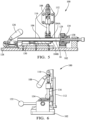
Fig. 1 shows a perspective view of an apparatus for a cutting shield conductor of a shielded electrical cable in an open condition according to an embodiment; -
Fig. 2 shows a perspective view of the apparatus ofFig. 1 in a closed condition according to an embodiment; -
Fig. 3 shows a top view of the apparatus ofFig. 1 according to an embodiment; -
Fig. 4 shows a side view of the apparatus ofFig. 1 according to an embodiment; -
Fig. 5 shows a cross-section side view of the apparatus ofFig. 1 along section line A-A ofFig. 5 according to an embodiment; -
Fig. 6 shows a top view of the apparatus ofFig. 1 according to an embodiment; and -
Fig. 7 shows a schematic side view of an arrangement of a cutting surface and cutting tube according to another embodiment; -
Fig. 8 shows a schematic side view of an arrangement of the shield conductor and the cutting surface in the apparatus ofFig. 7 after cutting according to the other embodiment; -
Fig. 9 shows a perspective view of a hinged cutting tube of the apparatus ofFig. 7 after cutting according to the other embodiment; and -
Fig. 10 shows a flow chart of a method of cutting a shield conductor of a shielded electrical cable using the apparatus ofFig. 1 . - Similar elements in the various examples illustrated herein may share the last two digits of the their reference numbers.
- The problem of operator-caused variation and the difficulty of flaring a shield conductor after it is secured within a shield cutting apparatus when trimming it to the desired length is solved by redesigning the apparatus and method to allow the shield conductor to be flared prior to inserting the high voltage electrical cable in the shield cutting apparatus. This innovative design also addresses some of the ergonomic shortcomings of prior shield cutting apparatus.
- A non-limiting example of an
apparatus 100 for cutting ashield conductor 10 of a shieldedelectrical cable 12 that has been previously flared outwardly from the shieldedelectrical cable 12 is shown inFigs. 1-6 . - The
apparatus 100 is built up from abase plate 102 to which the other components of theapparatus 100 are attached. Theapparatus 100 contains a two-piece clamping die 104 having anaperture 106 extending therethrough in which the shieldedelectrical cable 12 is secured. The two pieces or halves of theclamping die 104 are opened and closed around the shieldedelectrical cable 12 by a die clamping mechanism configured to move one or both the halves of theclamping die 104 relative to the other in a direction that is perpendicular to a longitudinal axis X of the shieldedelectrical cable 12, hereafter referred to as the lateral direction Y. In the illustrated example, the die clamping mechanism includes afirst lever 108 connected by afirst pivot 110 to a sideupright plate 112 attached to asliding plate 114. Thefirst lever 108 is also attached to afirst half 104A of theclamping die 104 by a first connectingrod 116. Thefirst lever 108 is configured to laterally movefirst half 104A of theclamping die 104 relative to thesecond half 104B of theclamping die 104 as shown by comparingFigs. 1 and2 . The die clamping mechanism also includes a T-shapedfirst guide rail 118 and correspondingfirst guide clamp 120 to ensure that thefirst half 104A of theclamping die 104 moves in the desired lateral direction Y as thefirst lever 108 is activated. - As best shown in
Figs. 2 and4 , the shieldedelectrical cable 12 is placed in theaperture 106 of theclamping die 104 so that the previously flaredshield conductor 10 is proximate a side surface of the clamping die that serves as acutting surface 122. - The
apparatus 100 further includes a die translation mechanism that is configured to move theclamping die 104 in a direction parallel to a longitudinal axis X of the shielded electrical cable, hereafter referred to as the longitudinal direction X. This longitudinal movement is configured to move theclamping die 104 and the shieldedelectrical cable 12 retained within it relative to acutting tube 124 that is configured to remove a portion of afree end 14 of theflared shield conductor 10. In the illustrated example, the die translation mechanism includes asecond lever 126 connected by asecond pivot 128 to thebase plate 102. Thesecond lever 126 is also attached to thesliding plate 114 by a second connectingrod 130. Thesecond lever 126 is configured to longitudinally move thesliding plate 114 and thereby theclamping die 104 relative to thecutting tube 124 as shown by comparingFigs. 1 and2 . - The
cutting tube 124 is a hollow tube that is configured to receive anend 16 of the shieldedelectrical cable 12. Thecutting surface 122 is pressed against thecutting tube 124 by the die translation mechanism while theflared shield conductor 10 is disposed between thecutting surface 122 and thecutting tube 124. Thecutting tube 124 is then rotated while thecutting surface 122 is pressed against thecutting tube 124, thereby cutting a portion of thefree end 14 of theflared shield conductor 10 and trimming theshield conductor 10 to the desired length for further processing, such as attachment of a connector or ferrule (not shown). Thecutting surface 122 may be characterized as having an annular shape. Theapparatus 100 also contains a cutting tube rotation mechanism that is configured to rotate thecutting tube 124 around the longitudinal axis X of the shieldedelectrical cable 12 while it is in contact with thecutting surface 122. The cutting tube rotation mechanism includes athird lever 132 connected to the cuttingtube 124. The cutting tube rotation mechanism further includes abearing 134 through which the cuttingtube 124 is secured to thebase plate 102 and allows the cuttingtube 124 to rotate about the longitudinal axis of the shieldedelectrical cable 12. The cuttingtube 124 further comprises afrustoconical guiding tool 136 configured to position the flaredshield conductor 10 between with the cuttingsurface 122 and the cuttingtube 124. - The
apparatus 100 additionally includes acable stop 138 that is configured to contact theend 16 of the shieldedelectrical cable 12, thereby positioning the flaredshield conductor 10 relative to the cuttingsurface 122 and the cuttingtube 124. - Another non-limiting example of an
apparatus 200 for cutting a shield conductor similar to theapparatus 100 is shown inFigs. 7-9 . This apparatus includes a two-piece clamshell-style cutting tube 224 (instead of the hollow one-piece cutting tube 124) that can be opened and closed around a stationary high voltage shielded electrical cable 12 (instead of requiring the cable to be inserted into the cutting tube 124). The cuttingtube 224 may include twosemi-cylindrical halves hinge 240 along a longitudinal seam as shown inFig. 9 . The die 204 further comprises afrustoconical guiding tool 236 configured to position the flaredshield conductor 10 between with the cuttingsurface 222 and the cuttingtube 224. The cuttingtube 224 is located on the opposite side of a die 204 defining a cuttingsurface 222 compared toapparatus 100, thereby eliminating the need for the operator to reach past thedie 204 and thus improving operator ergonomics and safety. - The
apparatus 200 additionally includes acable stop 238 that is configured to contact theend 16 of the shieldedelectrical cable 12, thereby positioning the flaredshield conductor 10 relative to the cuttingsurface 222 and the cuttingtube 224. - A
method 300 of cutting the shield conductor of a high voltage shielded electrical cable illustrated inFig. 10 includes the following steps: -
STEP 302, REMOVE THE OUTER INSULATION JACKET, includes removing a portion of the outer insulatingjacket 18 of the high voltage shieldedelectrical cable 12 to expose theshield conductor 10.STEP 302 may be performed manually or automatically using an insulation stripping tool; -
STEP 304, FLARE THE SHIELD CONDUCTOR, includes flaring the wires of thebraided shield conductor 10 outwardly from the high voltage shieldedelectrical cable 12.STEP 304 may be performed manually by a human operator or semiautomatically using a flaring tool; -
STEP 306, PLACE THE ELECTRICAL CABLE IN AN APERTURE OF A TWO-PIECE CLAMPING DIE, includes placing the shieldedelectrical cable 12 in anaperture 106 of a two-piece clamping die 104; -
STEP 308, MOVE PIECE OF THE CLAMPING DIE TOWARD THE OTHER PIECE OF THE CLAMPING DIE, includes moving at least one of the twopieces 104A of the clamping die 104 toward the other of the twopieces 104B of the clamping die 104 in a lateral direction Y perpendicular to the longitudinal axis X of the shieldedelectrical cable 12, thereby clamping the shieldedelectrical cable 12 within theaperture 106 of the clamping die 104; -
STEP 310, PRESS THE CUTTING TUBE AGAINST A CUTTING SURFACE OF THE CLAMPING DIE, includes pressing the cuttingtube 124 against a cuttingsurface 122 of the clamping die 104 with the flaredshield conductor 10 disposed between the cuttingtube 124 and the cuttingsurface 122; -
STEP 312, ROTATE THE CUTTING TUBE, includes rotating the cuttingtube 124 relative to the cuttingsurface 122 of the clamping die 104; -
STEP 314, CUT THROUGH THE FLARED SHIELD CONDUCTOR WITH AN EDGE OF THE CUTTING TUBE AS IT IS PRESSED AGAINST THE CUTTING SURFACE, includes cutting through the flaredshield conductor 10 with an edge of the cuttingtube 124 as it is pressed and rotated against the cuttingsurface 122; -
STEP 316, RETRACT THE CLAMPING DIE FROM BEING IN CONTACT WITH THE CUTTING TUBE, includes retracting the clamping die 104 from being in contact with the cuttingtube 124; -
STEP 318, MOVE ONE PIECE OF THE CLAMPING DIE AWAY FROM THE OTHER PIECE OF THE CLAMPING DIE, includes moving the at least one of the twopieces 104A of the clamping die 104 away from the other of the twopieces 104B of the clamping die 104 in the lateral direction Y, thereby releasing the shieldedelectrical cable 12 from theaperture 106 of the clamping die 104; and -
STEP 320, REMOVE THE HIGH VOLTAGE ELECTRICAL CABLE FROM THE CLAMPING DIE, includes removing the high voltage shieldedelectrical cable 12 from the clamping die 104 and thereby from theapparatus 100. - While the illustrated embodiments have been directed to high voltage shielded electrical cables, this apparatus and method may also be used with other shielded electrical cables, for example coaxial cables used to carry radio frequency or high frequency data signals.
- While the invention has been described with reference to an exemplary embodiment(s), it will be understood by those skilled in the art that various changes may be made, and equivalents may be substituted for elements thereof without departing from the scope of the invention. In addition, many modifications may be made to adapt a particular situation or material to the teachings of the invention without departing from the essential scope thereof. Therefore, it is intended that the invention is not limited to the disclosed embodiment(s), but that the invention will include all embodiments falling within the scope of the appended claims.
- As used herein, 'one or more' includes a function being performed by one element, a function being performed by more than one element, e.g., in a distributed fashion, several functions being performed by one element, several functions being performed by several elements, or any combination of the above.
- It will also be understood that, although the terms first, second, etc. are, in some instances, used herein to describe various elements, these elements should not be limited by these terms. These terms are only used to distinguish one element from another. For example, a first contact could be termed a second contact, and, similarly, a second contact could be termed a first contact, without departing from the scope of the various described embodiments. The first contact and the second contact are both contacts, but they are not the same contact.
- The terminology used in the description of the various described embodiments herein is for the purpose of describing particular embodiments only and is not intended to be limiting. As used in the description of the various described embodiments and the appended claims, the singular forms "a", "an" and "the" are intended to include the plural forms as well, unless the context clearly indicates otherwise. It will also be understood that the term "and/or" as used herein refers to and encompasses any and all possible combinations of one or more of the associated listed items. It will be further understood that the terms "includes," "including," "comprises," and/or "comprising," when used in this specification, specify the presence of stated features, integers, steps, operations, elements, and/or components, but do not preclude the presence or addition of one or more other features, integers, steps, operations, elements, components, and/or groups thereof.
- As used herein, the term "if' is, optionally, construed to mean "when" or "upon" or "in response to determining" or "in response to detecting," depending on the context. Similarly, the phrase "if it is determined" or "if [a stated condition or event] is detected" is, optionally, construed to mean "upon determining" or "in response to determining" or "upon detecting [the stated condition or event]" or "in response to detecting [the stated condition or event]," depending on the context.
- Additionally, while terms of ordinance or orientation may be used herein these elements should not be limited by these terms. All terms of ordinance or orientation, unless stated otherwise, are used for purposes distinguishing one element from another, and do not denote any particular order, order of operations, direction or orientation unless stated otherwise.
Claims (15)
- An apparatus (100) configured to cut a shield conductor (10) of a shielded electrical cable (12) that is flared outwardly from the shielded electrical cable, said apparatus (100) comprising:a two-piece clamping die (104) having an aperture extending therethrough in which the shielded electrical cable is secured and a cutting surface (122), wherein the two pieces of the clamping die (104A, 104B) are configured to be opened and closed around the shielded electrical cable (12); anda cutting tube (124) configured to receive an end (16) of the shielded electrical cable (12) and to press against the cutting surface (122) while the flared shield conductor (10) is disposed between the cutting tube (124) and the cutting surface (122), thereby cutting a portion of a free end (14) of the flared shield conductor (10).
- The apparatus (100) in accordance with claim 1, further comprising a die clamping mechanism (108, 110, 112, 114) configured to move at least one of the two pieces (104A, 104B) of the clamping die (104) relative to the other of the two pieces (104A, 104B) of the clamping die (104) in a direction perpendicular to a longitudinal axis (X) of the shielded electrical cable (12).
- The apparatus (100) in accordance with claim 1 or 2, further comprising a die translation mechanism (126, 128) configured to move the clamping die (104) in a direction parallel to a longitudinal axis (X) of the shielded electrical cable (12) relative to the cutting tube (124).
- The apparatus (100) in accordance with any one of the preceding claims, further comprising a cutting tube rotation mechanism (132, 134) configured to rotate the cutting tube (124) around a longitudinal axis (X) of the shielded electrical cable (12).
- The apparatus (100) in accordance with any one of the preceding claims, further comprising a cable stop (138) configured to contact the end (16) of the shielded electrical cable (12), thereby positioning the flared shield conductor (10) relative to the cutting tube (124) and cutting surface (122).
- The apparatus (100) in accordance with any one of the preceding claims, wherein the cutting surface (122) defines an annular shape.
- The apparatus (100) in accordance with any one of the preceding claims, wherein the cutting tube (124) further comprises a frustoconical guiding tool (136) configured to position the flared shield conductor (10) between with the cutting surface (122) and the cutting tube (124).
- A method (300) of cutting a shield conductor (10) of a high voltage shielded electrical cable (12), comprising:flaring (304) a free end (14) of the shield conductor ()10) outwardly from the high voltage shielded electrical cable (12);placing (306) the shielded electrical cable (12) in an aperture of a two-piece clamping die (104);moving (308) at least one of the two pieces (104A, 104B) of the clamping die (104) toward the other of the two pieces (104A, 104B) of the clamping die (104) in a direction perpendicular to a longitudinal axis (X) of the shielded electrical cable (12), thereby clamping the shielded electrical cable (12) within the aperture of the clamping die (104);disposing an end (16) of the shielded electrical cable (12) within a cutting tube (124);moving the clamping die (104) in a direction parallel to a longitudinal axis (X) of the shielded electrical cable (12) towards the cutting tube (124);pressing (310) the cutting tube (124) against a cutting surface (122) of the clamping die (104) with the flared shield conductor (10) disposed between the cutting tube (124) and the cutting surface (122);rotating (312) the cutting tube (124) relative to the cutting surface (122) of the clamping die (104); andcutting (314) through the flared shield conductor (12) with an edge of the cutting tube (124) as the cutting tube (124) is pressed against the cutting surface (122).
- The method (300) in accordance with claim 8, further comprising:retracting (316) the clamping die (104) from being in contact with the cutting tube (122);moving (318) the at least one of the two pieces (104A, 104B) of the clamping die (104) away from the other of the two pieces (104A, 104B) of the clamping die (104) in the direction perpendicular to the longitudinal axis (X) of the shielded electrical cable (12), thereby releasing the shielded electrical cable (12) from the aperture of the clamping die (104); andremoving (320) the high voltage shielded electrical cable (12) from the clamping die (104).
- The method (300) in accordance with claim 8 or 9, further comprising:
removing (302) a portion of an outer insulating jacket (18) of the high voltage shielded electrical cable (12) to expose the shield conductor (10). - An apparatus (200) configured to cut a shield conductor (10) of a shielded electrical cable (12) that is flared outwardly from the shielded electrical cable (12), said apparatus (200) comprising:a die (204) comprising a cutting surface (222) and an aperture extending therethrough, wherein the aperture is configured to receive an end (16) of the shielded electrical cable (12); anda cutting tube (224) having two parts (224A, 224B) that are configured to be closed about the shielded electrical cable (12) and pressed against the cutting surface (222) while the flared shield conductor (10) is disposed between the cutting tube (224) and the cutting surface (222), thereby cutting a portion of a free end (14) of the flared shield conductor (10).
- The apparatus (200) in accordance with claim 11, further comprising a cable stop (238) configured to contact the end (16) of the shielded electrical cable (12), thereby positioning the flared shield conductor (10) relative to the cutting tube (224) and cutting surface (222).
- The apparatus (200) in accordance with claim 11 or 12, wherein the apparatus (200) further comprises a frustoconical guiding tool (236) surrounding the aperture configured to guide the flared shield conductor (10) into contact with the cutting surface (222).
- The apparatus (200) in accordance with any one of the claims 11 to 13, wherein the two parts (224A, 224B) of the cutting tube (224) each have a semi-cylindrical shape and are joined along a longitudinal edge by a hinge feature (240), thereby forming a cylindrical cutting tube (224) when closed about the shielded electrical cable (12).
- The apparatus (200) in accordance with any one of the claims 11 to 14, wherein a diameter of the aperture is greater than a diameter of the flared shield conductor (10).
Applications Claiming Priority (2)
| Application Number | Priority Date | Filing Date | Title |
|---|---|---|---|
| US202163283952P | 2021-11-29 | 2021-11-29 | |
| US17/883,831 US12438347B2 (en) | 2021-11-29 | 2022-08-09 | Method of cutting shielding conductor of a high voltage cable and apparatus to be used therefore |
Publications (1)
| Publication Number | Publication Date |
|---|---|
| EP4187729A1 true EP4187729A1 (en) | 2023-05-31 |
Family
ID=84045000
Family Applications (1)
| Application Number | Title | Priority Date | Filing Date |
|---|---|---|---|
| EP22204357.2A Pending EP4187729A1 (en) | 2021-11-29 | 2022-10-28 | Method of cutting shielding conductor of a high voltage cable and apparatus to be used therefore |
Country Status (3)
| Country | Link |
|---|---|
| US (1) | US12438347B2 (en) |
| EP (1) | EP4187729A1 (en) |
| CN (1) | CN116174615A (en) |
Families Citing this family (1)
| Publication number | Priority date | Publication date | Assignee | Title |
|---|---|---|---|---|
| US20250385496A1 (en) * | 2024-06-17 | 2025-12-18 | Te Connectivity Solutions Gmbh | Method for Cable Braid Folding |
Citations (5)
| Publication number | Priority date | Publication date | Assignee | Title |
|---|---|---|---|---|
| US3721138A (en) * | 1969-09-04 | 1973-03-20 | Nippon Electric Co | Device for cutting an outer layer of the concentric multilayer rod-like structure |
| JPS5725113A (en) * | 1980-07-21 | 1982-02-09 | Hirose Electric Co Ltd | Method and device for treating terminal of coaxial cable |
| GB2099237A (en) * | 1981-05-27 | 1982-12-01 | Liney & Partners Ltd | Braid-cutting apparatus |
| EP1054494A2 (en) * | 1999-05-21 | 2000-11-22 | Harness System Technologies Research, Ltd. | Method and apparatus for cutting braided sheath of shielding wire |
| CN208226281U (en) * | 2018-03-21 | 2018-12-11 | 常州市禾昌机械有限公司 | A kind of gauze screen cutting machine |
Family Cites Families (18)
| Publication number | Priority date | Publication date | Assignee | Title |
|---|---|---|---|---|
| GB678181A (en) * | 1949-03-29 | 1952-08-27 | Gabriel Victor Alphonse Duch | Method and device for cutting cables, tubes, and the like |
| JP2829126B2 (en) * | 1990-11-28 | 1998-11-25 | 住友電装株式会社 | Winding type wire stripping method and device |
| US6243947B1 (en) * | 1998-09-22 | 2001-06-12 | Sumitomo Wiring Systems, Ltd. | Method for processing an end of a shielded cable |
| ATE270792T1 (en) * | 1999-11-01 | 2004-07-15 | Schleuniger Holding Ag | METHOD AND DEVICE FOR SEPARATING THE SHIELD FROM A CABLE |
| US6536103B1 (en) * | 2000-08-24 | 2003-03-25 | Holland Electronics, Llc | Tool for installing a coaxial cable connector |
| JP3790416B2 (en) * | 2000-11-06 | 2006-06-28 | 矢崎総業株式会社 | Shielding wire processing method and processing equipment |
| JP3908915B2 (en) * | 2001-03-02 | 2007-04-25 | 矢崎総業株式会社 | Braided cutting device for shielded wire and braided cutting method |
| JP2002262429A (en) * | 2001-03-02 | 2002-09-13 | Yazaki Corp | Shield wire braiding device and braid folding method |
| JP2005229770A (en) | 2004-02-16 | 2005-08-25 | Yazaki Corp | Braided cutting device for shielded wire |
| JP5362270B2 (en) * | 2008-07-03 | 2013-12-11 | 矢崎総業株式会社 | Shielded wire, braided terminal processing method of shielded wire, and braided terminal processing apparatus |
| DE102012020798B3 (en) * | 2012-10-23 | 2014-04-10 | Rosenberger Hochfrequenztechnik Gmbh & Co. Kg | Apparatus and method for processing an end of a cable |
| JP5725113B2 (en) * | 2013-09-20 | 2015-05-27 | 日本電気株式会社 | Battery pack and film-covered electrical device |
| CN104682168B (en) | 2015-02-18 | 2017-09-01 | 深圳市中海通机器人有限公司 | Metal braid processing device and automatic processing machine based on shielded cable |
| EP3163697B1 (en) | 2015-10-29 | 2020-09-02 | Lisa Dräxlmaier GmbH | Separating a shielding of a coaxial cable |
| JP6414272B1 (en) * | 2017-04-26 | 2018-10-31 | 住友電装株式会社 | Braiding processing apparatus and braided cable processing method |
| CN207165264U (en) * | 2017-08-16 | 2018-03-30 | 东莞市耀丰电线电缆有限公司 | A kind of anti-hydrolysis stretchable control line |
| DE102018117132B4 (en) * | 2018-07-16 | 2024-05-02 | Metzner Maschinenbau Gmbh | Apparatus and method for processing an end of an electrical cable |
| US11018483B2 (en) * | 2018-09-04 | 2021-05-25 | Te Connectivity Corporation | Cable preparation machine |
-
2022
- 2022-08-09 US US17/883,831 patent/US12438347B2/en active Active
- 2022-10-28 EP EP22204357.2A patent/EP4187729A1/en active Pending
- 2022-11-28 CN CN202211504072.0A patent/CN116174615A/en active Pending
Patent Citations (5)
| Publication number | Priority date | Publication date | Assignee | Title |
|---|---|---|---|---|
| US3721138A (en) * | 1969-09-04 | 1973-03-20 | Nippon Electric Co | Device for cutting an outer layer of the concentric multilayer rod-like structure |
| JPS5725113A (en) * | 1980-07-21 | 1982-02-09 | Hirose Electric Co Ltd | Method and device for treating terminal of coaxial cable |
| GB2099237A (en) * | 1981-05-27 | 1982-12-01 | Liney & Partners Ltd | Braid-cutting apparatus |
| EP1054494A2 (en) * | 1999-05-21 | 2000-11-22 | Harness System Technologies Research, Ltd. | Method and apparatus for cutting braided sheath of shielding wire |
| CN208226281U (en) * | 2018-03-21 | 2018-12-11 | 常州市禾昌机械有限公司 | A kind of gauze screen cutting machine |
Also Published As
| Publication number | Publication date |
|---|---|
| US12438347B2 (en) | 2025-10-07 |
| US20230170675A1 (en) | 2023-06-01 |
| CN116174615A (en) | 2023-05-30 |
Similar Documents
| Publication | Publication Date | Title |
|---|---|---|
| EP3618207B2 (en) | Cable braid flare mechanism for cable preparation machine | |
| US6363604B1 (en) | Method and apparatus for cutting braided sheath of shielding wire | |
| US6604268B1 (en) | Apparatus for processing an end of a shielded cable | |
| KR20010070183A (en) | Method and apparatus for stripping and removing the shielding from a cable | |
| TWI631784B (en) | Device for processing cable end | |
| US12438347B2 (en) | Method of cutting shielding conductor of a high voltage cable and apparatus to be used therefore | |
| EP3163697B1 (en) | Separating a shielding of a coaxial cable | |
| US9997886B2 (en) | Method of forming termination end on cable | |
| KR102686605B1 (en) | Apparatus and process for manufacturing terminal sections of shielded electrical cables | |
| JP7157100B2 (en) | Braid cuff cutting device and braid cuff cutting method | |
| JP2021114464A (en) | Apparatus, tool, and method for forming apparatus | |
| GB2063583A (en) | Coaxial cable end connection | |
| US8609989B2 (en) | Electrical cable and method and device for the manufacture thereof | |
| US4953428A (en) | Tool for stripping cables, in particular constituted cables | |
| US5619790A (en) | Method and apparatus for making an electrical connection | |
| JP7181243B2 (en) | Braid folding device and braid folding method | |
| CN113224691B (en) | Fabric cutting unit and fabric cutting method | |
| EP4340144A1 (en) | Apparatus and process for removing an end portion of the shielding foil of a shielded electric cable | |
| US3707041A (en) | Shield termination apparatus | |
| HK40033330A (en) | Apparatus and process for preparing an end portion of a shielded electrical cable | |
| HK40033330B (en) | Apparatus and process for preparing an end portion of a shielded electrical cable | |
| JPH079549Y2 (en) | Stripper for flat shielded cable | |
| EP1655812A1 (en) | Connector removal device |
Legal Events
| Date | Code | Title | Description |
|---|---|---|---|
| PUAI | Public reference made under article 153(3) epc to a published international application that has entered the european phase |
Free format text: ORIGINAL CODE: 0009012 |
|
| STAA | Information on the status of an ep patent application or granted ep patent |
Free format text: STATUS: THE APPLICATION HAS BEEN PUBLISHED |
|
| AK | Designated contracting states |
Kind code of ref document: A1 Designated state(s): AL AT BE BG CH CY CZ DE DK EE ES FI FR GB GR HR HU IE IS IT LI LT LU LV MC ME MK MT NL NO PL PT RO RS SE SI SK SM TR |
|
| STAA | Information on the status of an ep patent application or granted ep patent |
Free format text: STATUS: REQUEST FOR EXAMINATION WAS MADE |
|
| 17P | Request for examination filed |
Effective date: 20231124 |
|
| RBV | Designated contracting states (corrected) |
Designated state(s): AL AT BE BG CH CY CZ DE DK EE ES FI FR GB GR HR HU IE IS IT LI LT LU LV MC ME MK MT NL NO PL PT RO RS SE SI SK SM TR |
|
| RAP1 | Party data changed (applicant data changed or rights of an application transferred) |
Owner name: APTIV TECHNOLOGIES AG |
|
| RAP3 | Party data changed (applicant data changed or rights of an application transferred) |
Owner name: APTIV TECHNOLOGIES AG |
|
| STAA | Information on the status of an ep patent application or granted ep patent |
Free format text: STATUS: EXAMINATION IS IN PROGRESS |
|
| 17Q | First examination report despatched |
Effective date: 20260408 |