EP4187692A1 - Battery cell and battery module comprising same - Google Patents
Battery cell and battery module comprising same Download PDFInfo
- Publication number
- EP4187692A1 EP4187692A1 EP22749900.1A EP22749900A EP4187692A1 EP 4187692 A1 EP4187692 A1 EP 4187692A1 EP 22749900 A EP22749900 A EP 22749900A EP 4187692 A1 EP4187692 A1 EP 4187692A1
- Authority
- EP
- European Patent Office
- Prior art keywords
- battery cell
- lead film
- lead
- dented portion
- cell according
- Prior art date
- Legal status (The legal status is an assumption and is not a legal conclusion. Google has not performed a legal analysis and makes no representation as to the accuracy of the status listed.)
- Granted
Links
Images



Classifications
-
- H—ELECTRICITY
- H01—ELECTRIC ELEMENTS
- H01M—PROCESSES OR MEANS, e.g. BATTERIES, FOR THE DIRECT CONVERSION OF CHEMICAL ENERGY INTO ELECTRICAL ENERGY
- H01M50/00—Constructional details or processes of manufacture of the non-active parts of electrochemical cells other than fuel cells, e.g. hybrid cells
- H01M50/10—Primary casings; Jackets or wrappings
- H01M50/183—Sealing members
- H01M50/186—Sealing members characterised by the disposition of the sealing members
-
- H—ELECTRICITY
- H01—ELECTRIC ELEMENTS
- H01M—PROCESSES OR MEANS, e.g. BATTERIES, FOR THE DIRECT CONVERSION OF CHEMICAL ENERGY INTO ELECTRICAL ENERGY
- H01M50/00—Constructional details or processes of manufacture of the non-active parts of electrochemical cells other than fuel cells, e.g. hybrid cells
- H01M50/10—Primary casings; Jackets or wrappings
- H01M50/183—Sealing members
- H01M50/184—Sealing members characterised by their shape or structure
-
- H—ELECTRICITY
- H01—ELECTRIC ELEMENTS
- H01M—PROCESSES OR MEANS, e.g. BATTERIES, FOR THE DIRECT CONVERSION OF CHEMICAL ENERGY INTO ELECTRICAL ENERGY
- H01M50/00—Constructional details or processes of manufacture of the non-active parts of electrochemical cells other than fuel cells, e.g. hybrid cells
- H01M50/10—Primary casings; Jackets or wrappings
- H01M50/102—Primary casings; Jackets or wrappings characterised by their shape or physical structure
- H01M50/105—Pouches or flexible bags
-
- H—ELECTRICITY
- H01—ELECTRIC ELEMENTS
- H01M—PROCESSES OR MEANS, e.g. BATTERIES, FOR THE DIRECT CONVERSION OF CHEMICAL ENERGY INTO ELECTRICAL ENERGY
- H01M50/00—Constructional details or processes of manufacture of the non-active parts of electrochemical cells other than fuel cells, e.g. hybrid cells
- H01M50/10—Primary casings; Jackets or wrappings
- H01M50/172—Arrangements of electric connectors penetrating the casing
- H01M50/174—Arrangements of electric connectors penetrating the casing adapted for the shape of the cells
- H01M50/178—Arrangements of electric connectors penetrating the casing adapted for the shape of the cells for pouch or flexible bag cells
-
- H—ELECTRICITY
- H01—ELECTRIC ELEMENTS
- H01M—PROCESSES OR MEANS, e.g. BATTERIES, FOR THE DIRECT CONVERSION OF CHEMICAL ENERGY INTO ELECTRICAL ENERGY
- H01M50/00—Constructional details or processes of manufacture of the non-active parts of electrochemical cells other than fuel cells, e.g. hybrid cells
- H01M50/10—Primary casings; Jackets or wrappings
- H01M50/183—Sealing members
- H01M50/186—Sealing members characterised by the disposition of the sealing members
- H01M50/188—Sealing members characterised by the disposition of the sealing members the sealing members being arranged between the lid and terminal
-
- H—ELECTRICITY
- H01—ELECTRIC ELEMENTS
- H01M—PROCESSES OR MEANS, e.g. BATTERIES, FOR THE DIRECT CONVERSION OF CHEMICAL ENERGY INTO ELECTRICAL ENERGY
- H01M50/00—Constructional details or processes of manufacture of the non-active parts of electrochemical cells other than fuel cells, e.g. hybrid cells
- H01M50/10—Primary casings; Jackets or wrappings
- H01M50/183—Sealing members
- H01M50/19—Sealing members characterised by the material
-
- H—ELECTRICITY
- H01—ELECTRIC ELEMENTS
- H01M—PROCESSES OR MEANS, e.g. BATTERIES, FOR THE DIRECT CONVERSION OF CHEMICAL ENERGY INTO ELECTRICAL ENERGY
- H01M50/00—Constructional details or processes of manufacture of the non-active parts of electrochemical cells other than fuel cells, e.g. hybrid cells
- H01M50/10—Primary casings; Jackets or wrappings
- H01M50/183—Sealing members
- H01M50/19—Sealing members characterised by the material
- H01M50/193—Organic material
-
- H—ELECTRICITY
- H01—ELECTRIC ELEMENTS
- H01M—PROCESSES OR MEANS, e.g. BATTERIES, FOR THE DIRECT CONVERSION OF CHEMICAL ENERGY INTO ELECTRICAL ENERGY
- H01M50/00—Constructional details or processes of manufacture of the non-active parts of electrochemical cells other than fuel cells, e.g. hybrid cells
- H01M50/10—Primary casings; Jackets or wrappings
- H01M50/183—Sealing members
- H01M50/19—Sealing members characterised by the material
- H01M50/198—Sealing members characterised by the material characterised by physical properties, e.g. adhesiveness or hardness
-
- H—ELECTRICITY
- H01—ELECTRIC ELEMENTS
- H01M—PROCESSES OR MEANS, e.g. BATTERIES, FOR THE DIRECT CONVERSION OF CHEMICAL ENERGY INTO ELECTRICAL ENERGY
- H01M50/00—Constructional details or processes of manufacture of the non-active parts of electrochemical cells other than fuel cells, e.g. hybrid cells
- H01M50/20—Mountings; Secondary casings or frames; Racks, modules or packs; Suspension devices; Shock absorbers; Transport or carrying devices; Holders
- H01M50/204—Racks, modules or packs for multiple batteries or multiple cells
- H01M50/207—Racks, modules or packs for multiple batteries or multiple cells characterised by their shape
- H01M50/211—Racks, modules or packs for multiple batteries or multiple cells characterised by their shape adapted for pouch cells
-
- H—ELECTRICITY
- H01—ELECTRIC ELEMENTS
- H01M—PROCESSES OR MEANS, e.g. BATTERIES, FOR THE DIRECT CONVERSION OF CHEMICAL ENERGY INTO ELECTRICAL ENERGY
- H01M50/00—Constructional details or processes of manufacture of the non-active parts of electrochemical cells other than fuel cells, e.g. hybrid cells
- H01M50/30—Arrangements for facilitating escape of gases
-
- H—ELECTRICITY
- H01—ELECTRIC ELEMENTS
- H01M—PROCESSES OR MEANS, e.g. BATTERIES, FOR THE DIRECT CONVERSION OF CHEMICAL ENERGY INTO ELECTRICAL ENERGY
- H01M50/00—Constructional details or processes of manufacture of the non-active parts of electrochemical cells other than fuel cells, e.g. hybrid cells
- H01M50/30—Arrangements for facilitating escape of gases
- H01M50/342—Non-re-sealable arrangements
- H01M50/3425—Non-re-sealable arrangements in the form of rupturable membranes or weakened parts, e.g. pierced with the aid of a sharp member
-
- H—ELECTRICITY
- H01—ELECTRIC ELEMENTS
- H01M—PROCESSES OR MEANS, e.g. BATTERIES, FOR THE DIRECT CONVERSION OF CHEMICAL ENERGY INTO ELECTRICAL ENERGY
- H01M50/00—Constructional details or processes of manufacture of the non-active parts of electrochemical cells other than fuel cells, e.g. hybrid cells
- H01M50/30—Arrangements for facilitating escape of gases
- H01M50/394—Gas-pervious parts or elements
-
- H—ELECTRICITY
- H01—ELECTRIC ELEMENTS
- H01M—PROCESSES OR MEANS, e.g. BATTERIES, FOR THE DIRECT CONVERSION OF CHEMICAL ENERGY INTO ELECTRICAL ENERGY
- H01M50/00—Constructional details or processes of manufacture of the non-active parts of electrochemical cells other than fuel cells, e.g. hybrid cells
- H01M50/50—Current conducting connections for cells or batteries
- H01M50/531—Electrode connections inside a battery casing
- H01M50/54—Connection of several leads or tabs of plate-like electrode stacks, e.g. electrode pole straps or bridges
-
- Y—GENERAL TAGGING OF NEW TECHNOLOGICAL DEVELOPMENTS; GENERAL TAGGING OF CROSS-SECTIONAL TECHNOLOGIES SPANNING OVER SEVERAL SECTIONS OF THE IPC; TECHNICAL SUBJECTS COVERED BY FORMER USPC CROSS-REFERENCE ART COLLECTIONS [XRACs] AND DIGESTS
- Y02—TECHNOLOGIES OR APPLICATIONS FOR MITIGATION OR ADAPTATION AGAINST CLIMATE CHANGE
- Y02E—REDUCTION OF GREENHOUSE GAS [GHG] EMISSIONS, RELATED TO ENERGY GENERATION, TRANSMISSION OR DISTRIBUTION
- Y02E60/00—Enabling technologies; Technologies with a potential or indirect contribution to GHG emissions mitigation
- Y02E60/10—Energy storage using batteries
Definitions
- the dented portion may be located in at least one of the first lead film and the second lead film.
- the dented portion 450 may be preserved in a non-sealed state by the inner layer 410.
- the width of the lead film 400 may be greater than the width of the sealing portion 250 and may be smaller than the length of the electrode lead 300.
- the length of the lead film 400 means a maximum value of the distance between one end and the other end of the lead film 400 in the protruding direction of the electrode lead 300.
- the width of the sealing portion 250 means a maximum value of the distance between one end and the other end of the sealing portion 250 in the protruding direction of the electrode lead 300.
- the length of the electrode lead 300 means a maximum value of the distance between one end and the other end of the electrode lead 300 in the protruding direction of the electrode lead 300.
- the second dented portion 455 may be located between the end of the sealing portion 250 and the end of the lead film 400.
- the second dented portion 455 may be entirely located at a position that does not correspond to the sealing portion 250.
Landscapes
- Chemical & Material Sciences (AREA)
- Chemical Kinetics & Catalysis (AREA)
- Electrochemistry (AREA)
- General Chemical & Material Sciences (AREA)
- Sealing Battery Cases Or Jackets (AREA)
- Gas Exhaust Devices For Batteries (AREA)
- Connection Of Batteries Or Terminals (AREA)
Abstract
Description
- The present application claims priority to
Korean Patent Application No. 10-2021-0016111 filed on February 4, 2021 - The present disclosure relates to a battery cell and a battery module including the same, and more particularly, to a battery cell with improved external emission of gas generated inside the battery cell, and a battery module including the same.
- As technology development and demand for mobile devices increase, the demand for secondary batteries as an energy source is rapidly increasing. In particular, secondary batteries are of great interest as energy sources not only for mobile devices such as mobile phones, digital cameras, notebooks and wearable devices, but also for power devices such as electric bicycles, electric vehicles and hybrid electric vehicles.
- Depending on the shape of a battery case, these secondary batteries are classified into a cylindrical battery and a prismatic battery in which a battery assembly is included in a cylindrical or prismatic metal can, and a pouch-type battery in which the battery assembly is included in a pouch-type case of an aluminum laminate sheet. Here, the battery assembly included in the battery case is a power element including a positive electrode, a negative electrode, and a separator interposed between the positive electrode and the negative electrode, and capable of charging and discharging, and is classified into a jelly-roll type in which long sheet-type positive and negative electrodes coated with an active material are wound with a separator being interposed therebetween, and a stack type in which a plurality of positive and negative electrodes are sequentially stacked with a separator being interposed therebetween.
- Among them, in particular, a pouch-type battery in which a stack-type or stack/folding-type battery assembly is included in a pouch-type battery case made of an aluminum laminate sheet is being used more and more due to low manufacturing cost, small weight, and easy modification.
-
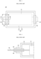
FIG. 1 is a top view showing a conventional battery cell.FIG. 2 is a cross-sectional view, taken along the axis a-a' ofFIG. 1 . Referring toFIGS. 1 and 2 , aconventional battery cell 10 includes abattery case 20 having anaccommodation portion 21 in which abattery assembly 11 is mounted, and asealing portion 25 formed by sealing an outer periphery thereof. Here, thebattery cell 10 includes anelectrode lead 30 protruding out of thebattery case 20 via thesealing portion 25, and alead film 40 is located between upper and lower portions of theelectrode lead 30 and thesealing portion 25. - However, as the energy density of the battery cell increases in recent years, there is a problem that the amount of gas generated inside the battery cell also increases. In the case of the
conventional battery cell 10, a component capable of discharging the gas generated inside the battery cell is not included, so a venting may occur in the battery cell due to gas generation. In addition, moisture may penetrate into the battery cell damaged by the venting, which may cause side reactions, and there is a problem that battery performance deteriorates and additional gas is generated. Accordingly, there is an increasing need to develop a battery cell with improved external emission of gas generated inside the battery cell. - The present disclosure is directed to providing a battery cell with improved external emission of gas generated inside the battery cell, and a battery module including the same.
- The object to be solved by the present disclosure is not limited to the above-mentioned object, and the objects not mentioned here may be clearly understood by those skilled in the art from this specification and the accompanying drawings.
- In one aspect of the present disclosure, there is provided a battery cell, comprising:
a battery case having an accommodation portion in which an electrode assembly is mounted, and a sealing portion formed by sealing an outer periphery thereof; an electrode lead electrically connected to an electrode tab included in the electrode assembly and protruding out of the battery case via the sealing portion; and a lead film located at a portion corresponding to the sealing portion in at least one of an upper portion and a lower portion of the electrode lead, wherein the lead film has a dented portion that is recessed in an outer direction of the battery case, the dented portion is opened toward the inside of the battery case, the dented portion includes a first dented portion and a second dented portion, and a width of the second dented portion is greater than a width of the first dented portion. - The second dented portion may be located farther from the accommodated electrode assembly than the first dented portion.
- A part of the first dented portion may be located at a position corresponding to the sealing portion.
- A part of the second dented portion may be located at a positon not corresponding to the sealing portion.
- The lead film may have a width greater than a width of the sealing portion and smaller than a length of the electrode lead.
- The second dented portion may be located between an end of the sealing portion and an end of the lead film.
- The first dented portion may extend along a protruding direction of the electrode lead, and the second dented portion may extend along a longitudinal direction of the sealing portion.
- The second dented portion may have a circular, triangular, rectangular or uneven shape.
- An inner surface of the dented portion may be closed based on a protruding direction of the electrode lead.
- The lead film may further include an inner layer configured to cover at least one surface of inner surfaces of the dented portion of the lead film.
- A material of the inner layer may have a higher melting point compared to a material of the lead film and may not react with an electrolytic solution.
- The lead film may contain a polyolefin-based material.
- The inner layer may contain at least one of polyolefin-based materials, fluorine-based materials and porous ceramic-based materials.
- The dented portion may be located over the electrode lead.
- The lead film may have a length greater than a width of the electrode lead.
- The dented portion may be located between an end of the electrode lead and an end of the lead film.
- The lead film may include a first lead film and a second lead film, the first lead film may be located at an upper portion of the electrode lead, and the second lead film may be located at a lower portion of the electrode lead.
- The electrode lead may be located between the first lead film and the second lead film, and the first lead film and the second lead film may be connected to each other.
- The dented portion may be located in at least one of the first lead film and the second lead film.
- An end of the dented portion at an outermost side of the battery case may be located outer than an outer surface of the battery case.
- An end of the dented portion opened toward the inside of the battery case may be located inner than an inner surface of the battery case.
- Based on a protruding direction of the electrode lead, a width of the lead film surrounding a front surface of the dented portion may be 2 mm or more.
- A thickness of the lead film surrounding an upper surface of the dented portion may be 100 µm to 300 µm.
- The lead film may have gas permeability of 20 Barrer to 60 Barrer at 60°C.
- The lead film may have a moisture penetration amount of 0.02 g to 0.2 g for 10 years at 25°C, 50 %RH.
- In another aspect of the present disclosure, there is also provided a battery module, comprising the battery cell described above.
- According to the embodiments, the present disclosure provides a battery cell, which includes an electrode lead to which a lead film having a dented portion dented in the outer direction of the battery case and opened toward the inside of the battery case is formed, and a battery module including the battery cell, thereby improving the external emission of gas generated inside the battery cell.
- According to embodiments, in the present disclosure, since the dented portion includes a first dented portion and a second dented portion so that the width of the second dented portion is greater than the width of the first dented portion, it is possible to improve the external emission of gas generated inside the battery cell and to improve the durability of the lead film.
- The effect of the present disclosure is not limited to the above effects, and the effects not mentioned here will be clearly understood by those skilled in the art from this specification and the accompanying drawings.
-
-
FIG. 1 is a top view showing a conventional battery cell. -
FIG. 2 is a cross-sectional view, taken along the axis a-a' ofFIG. 1 . -
FIG. 3 is a top view showing a battery cell according to this embodiment. -
FIG. 4 is a perspective view showing an electrode lead included in the battery cell ofFIG. 3 . -
FIG. 5 is a cross-sectional view, taken along the axis c-c' ofFIG. 4 . -
FIG. 6 is a cross-sectional view, taken along the axis d-d' ofFIG. 4 . -
FIG. 7 is a cross-sectional view, taken along the axis e-e' ofFIG. 4 . -
FIG. 8 is an enlarged view showing the electrode lead in the battery cell ofFIG. 3 . -
FIG. 9 is an enlarged view showing the electrode lead according to a location of the sealing portion in (a) ofFIG. 8 . -
FIG. 10 is an enlarged view showing the electrode lead in the battery cell ofFIG. 3 according to another embodiment of the present disclosure. -
FIG. 11 is an enlarged view showing the electrode lead in the battery cell ofFIG. 3 according to another embodiment of the present disclosure. -
FIG. 12 is an enlarged view showing the electrode lead in the battery cell ofFIG. 3 according to another embodiment of the present disclosure. -
FIG. 13 is a cross-sectional view, taken along the axis b-b' ofFIG. 3 . -
FIG. 14 is a diagram showing the flow of gas generated in the battery cell and discharged to the outside inFIG. 13 . - Hereinafter, with reference to the accompanying drawings, various embodiments of the present disclosure will be described in detail so as to be easily implemented by those skilled in the art. The present disclosure may be implemented in various different forms and is not limited to the embodiments described herein.
- In order to clearly explain the present disclosure, parts irrelevant to the description are omitted, and identical or similar components are endowed with the same reference signs throughout the specification.
- In addition, since the size and thickness of each component shown in the drawings are arbitrarily expressed for convenience of description, the present disclosure is not necessarily limited to the drawings. In order to clearly express various layers and regions in the drawings, the thicknesses are enlarged. Also, in the drawings, for convenience of explanation, the thickness of some layers and regions is exaggerated.
- In addition, throughout the specification, when a part "includes" a certain component, it means that other components may be further included, rather than excluding other components, unless otherwise stated.
- In addition, throughout the specification, when referring to "top view", it means that the target part is viewed from above, and when referring to "cross-sectional view", it means that a vertically-cut section of the target part is viewed from a side.
- Hereinafter, a
pouch battery cell 100 according to an embodiment of the present disclosure will be described. However, here, the description will be made based on one side surface of both side surfaces of thepouch battery cell 100, but it is not necessarily limited thereto, and the same or similar contents may be described in the case of the other side surface. -
FIG. 3 is a top view showing a battery cell according to this embodiment. - Referring to
FIG. 3 , thebattery cell 100 according to this embodiment includes abattery case 200, anelectrode lead 300, and alead film 400. - The
battery case 200 includes anaccommodation portion 210 in which anelectrode assembly 110 is mounted, and a sealingportion 250 formed by sealing an outer periphery thereof. The sealingportion 250 may be sealed by heat, laser, or the like. Thebattery case 200 may be a laminate sheet including a resin layer and a metal layer. More specifically, thebattery case 200 may be made of a laminate sheet, and may include an outer resin layer forming the outermost layer, a barrier metal layer preventing penetration of materials, and an inner resin layer for sealing. - Also, the
electrode assembly 110 may have a structure of a jelly-roll type (winding type), a stack type (lamination type), or a composite type (stack/folding type). More specifically, theelectrode assembly 110 may include a positive electrode, a negative electrode, and a separator disposed therebetween. - Hereinafter, the
electrode lead 300 and thelead film 400 will be mainly described. -
FIG. 4 is a perspective view showing an electrode lead included in the battery cell ofFIG. 3 . - Referring to
FIGS. 3 and 4 , theelectrode lead 300 is electrically connected to an electrode tab (not shown) included in theelectrode assembly 110, and protrudes out of thebattery case 200 via the sealingportion 250. In addition, thelead film 400 is located at a portion corresponding to the sealingportion 250 in at least one of an upper portion and a lower portion of theelectrode lead 300. Accordingly, thelead film 400 may improve the sealing properties of the sealingportion 250 and theelectrode lead 300 while preventing a short circuit from occurring in theelectrode lead 300 during sealing. -
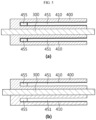
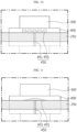
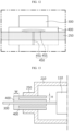
FIG. 5 is a cross-sectional view, taken along the axis c-c' ofFIG. 4 .FIG. 6 is a cross-sectional view, taken along the axis d-d' ofFIG. 4 .FIG. 7 is a cross-sectional view, taken along the axis e-e' ofFIG. 4 . - Referring to
FIG. 5 , thelead film 400 has a dentedportion 450 that is recessed in an outer direction of thebattery case 200, and the dentedportion 450 is opened toward the inside of thebattery case 200. In addition, the inner surface of the dentedportion 450 may be closed based on the protruding direction of theelectrode lead 300. - Accordingly, in the
lead film 400, if the gas generated inside thebattery case 200 exceeds a predetermined pressure, the gas may be discharged to the dentedportion 450, and the gas introduced into the dentedportion 450 may be discharged to the outside of the battery according to the pressure difference between the inside and outside. In addition, since the dentedportion 450 of thelead film 400 is opened toward the inside and simultaneously the inner surface of the dented portion recessed in the outward direction of thelead film 400 is closed, there is an advantage in that airtightness and durability of the pouch can also be secured. In addition, in thelead film 400, the gas permeation area may be maximized by the dentedportion 450, so that a large amount of gas can be discharged. - Referring to
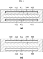
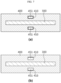
FIGS. 6 and7 , the dentedportion 450 includes a first dentedportion 451 and a second dentedportion 455, and the width of the second dentedportion 455 is greater than the width of the first dentedportion 451. - In this specification, the width of the second dented
portion 455 refers to a maximum value of the distance between one end and the other end of the second dentedportion 455 in a direction orthogonal to the protruding direction of theelectrode lead 300, and the width of the first dentedportion 451 refers to a maximum value of the distance between one end and the other end of the first dentedportion 451 in a direction orthogonal to the protruding direction of theelectrode lead 300. - If the curvature generated as the
lead film 400 expands to the outside by pressure increases since the gas inside thebattery case 200 flows into the dentedportion 450, the stress applied to the interface between thelead film 400 and theelectrode lead 300 also increases. - If the dented
portion 450 has the same width entirely, as the curvature of the expandedlead film 400 increases, the durability of thelead film 400 may be weakened due to the stress applied to the interface between thelead film 400 and theelectrode lead 300. - Meanwhile, if the dented
portion 450 includes the first dentedportion 451 and the second dentedportion 455 having different widths, since the curvature of thelead film 400 expanded in the first dentedportion 451 having a relatively small width is smaller than the curvature of thelead film 400 expanded in the second dentedportion 455 having a relatively great width, the stress applied to the interface of thelead film 400 and theelectrode lead 300 is small, so it is possible to improve durability and improve gas emission. - In addition, referring to
FIGS. 5 to 7 , thelead film 400 may further include aninner layer 410 covering at least one of the inner surfaces of the dentedportion 450. - For example, referring to
FIGS. 5(a) to 7(a) , theinner layer 410 in the dentedportion 450 may cover the entire surface of thelead film 400. That is, theinner layer 410 may be formed on the entire inner surface of the dentedportion 450, except for the opened surface. - Accordingly, even if the
lead film 400 is sealed together with the sealingportion 250 in a state of being located in at least one of the upper and lower portions of theelectrode lead 300, the dentedportion 450 may be preserved in a non-sealed state by theinner layer 410. - As another example, referring to
FIGS. 5(b) to 7(b) , theinner layer 410 may cover an upper surface or a lower surface among the inner surfaces of the dentedportion 450. That is, the dentedportion 450 may have aninner layer 410 formed on at least one of the upper and lower surfaces facing each other. - Accordingly, while the
lead film 400 minimizes theinner layer 410 formed in the dentedportion 450, the dentedportion 450 may be preserved in a non-sealed state by theinner layer 410. In addition, the manufacturing process may be simplified and the cost may be reduced. - More specifically, the
inner layer 410 may be made of a material having a higher melting point compared to the material constituting thelead film 400. In addition, theinner layer 410 may be made of a material that does not react with the electrolytic solution contained in thebattery case 200. Accordingly, since theinner layer 410 is made of the above-described material, theinner layer 410 does not separately react with the electrolytic solution and does not cause heat fusion, thermal deformation, or the like in the high-temperature sealing process, so that the dentedportion 450 may be kept blank. In addition, the gas generated in thebattery case 200 may be easily discharged to the outside. - In one embodiment of the present disclosure, the thickness of the
inner layer 410 may be 100 µm or less. - In one embodiment of the present disclosure, the gas permeability of the
inner layer 410 may be 40 Barrer or more. For example, the carbon dioxide permeability of theinner layer 410 may satisfy the above range. - For example, the
inner layer 410 may include at least one of polyolefin-based materials, fluorine-based materials, and porous ceramic-based materials. For example, theinner layer 410 may include at least one of polyolefin-based materials, fluorine-based materials, and porous ceramic-based materials that satisfies the above gas permeability value. The polyolefin-based material may include at least one material selected from the group consisting of polypropylene, polyethylene, and polyvinyl difluoride (PVDF). The fluorine-based material may include at least one material selected from the group consisting of polytetrafluoroethylene and polyvinylidene fluoride. In addition, theinner layer 410 may include a getter material, so that gas permeability may be increased while water permeability may be minimized. As an example, the getter material may be calcium oxide (CaO), barium oxide (BaO), lithium chloride (LiCl), silica (SiO2), or the like, and any material reacting with water (H2O) can be used without being limited thereto. - The
inner layer 410 may have an adhesive material between thelead film 400 and theinner layer 410 or may be extruded together with thelead film 400 and adhered to thelead film 400. The adhesive material may include an acryl-based material. In particular, when theinner layer 410 is extruded together with thelead film 400, the gas permeability of theinner layer 410 may be 40 Barrer or more. - Referring to
FIGS. 4 to 7 , thelead film 400 may include a first lead film and a second lead film, the first lead film may be located at an upper portion of theelectrode lead 300, and the second lead film may be located at a lower portion of theelectrode lead 300. At this time, theelectrode lead 300 may be sealed together with the sealingportion 250 in a state of being located between the first lead film and the second lead film, so that the first lead film and the second lead film may be connected to each other. - Accordingly, the
lead film 400 may prevent the side surface of theelectrode lead 300 from being exposed to the outside, while improving the sealing properties of the sealingportion 250 and theelectrode lead 300. - For example, in the
lead film 400, the dentedportion 450 may be located in at least one of the first lead film and the second lead film. More specifically, in thelead film 400, the dentedportion 450 may be formed in the first lead film or the second lead film based on theelectrode lead 300, or the dentedportion 450 may be formed in both the first lead film and the second lead film based on theelectrode lead 300. However, the number of the dentedportion 450 is not limited to the above, and thelead film 400 may be formed in an appropriate number. - Accordingly, by adjusting the number of the dented
portions 450 formed in thelead film 400, the durability and airtightness of thelead film 400 may be controlled. In addition, by minimizing the number of the dentedportion 450 as necessary, it is possible to simplify the manufacturing process and reduce the cost. -
FIG. 8 is an enlarged view showing the electrode lead in the battery cell ofFIG. 3 .FIG. 9 is an enlarged view showing the electrode lead according to a location of the sealing portion in (a) ofFIG. 8 . - Referring to
FIG. 8 , the second dentedportion 455 may be located farther from the accommodatedelectrode assembly 110 than the first dentedportion 451. - At this time, the second dented
portion 455 may play a role of discharging the gas generated inside thebattery case 200 to the outside of thebattery case 200. Accordingly, since the width of the second dentedportion 455 is greater than the width of the first dentedportion 451, the area through which the gas is discharged to the outside is further increased, and thus it may be easier to increase the emission of gas. - In addition, the first dented
portion 451 having a relatively smaller width may serve as a passage through which the gas generated inside thebattery case 200 flows into the dentedportion 450, and may increase durability of thelead film 400. - Referring to
FIG. 8 , a part of the first dentedportion 451 may be located at a position corresponding to the sealingportion 250. For example, the second dentedportion 455 may be located farther from the accommodatedelectrode assembly 110 than the first dentedportion 451, and also a part of the first dentedportion 451 may be located at a position corresponding to the sealingportion 250. - Referring to
FIG. 8 , a part of the second dentedportion 455 may be located at a position that does not correspond to the sealingportion 250. In this case, as the area in which the second dentedportion 455 does not correspond to the sealingportion 250 increases, the area in which the gas inside thebattery case 200 is discharged to the outside of thebattery case 200 may increase. For example, while the second dentedportion 455 is located farther from the accommodatedelectrode assembly 110 than the first dentedportion 451, a part of the second dentedportion 455 may be located at a position that does not correspond to the sealingportion 250. - In an embodiment of the present disclosure, the width of the
lead film 400 may be greater than the width of the sealingportion 250 and may be smaller than the length of theelectrode lead 300. In this specification, the length of thelead film 400 means a maximum value of the distance between one end and the other end of thelead film 400 in the protruding direction of theelectrode lead 300. The width of the sealingportion 250 means a maximum value of the distance between one end and the other end of the sealingportion 250 in the protruding direction of theelectrode lead 300. The length of theelectrode lead 300 means a maximum value of the distance between one end and the other end of theelectrode lead 300 in the protruding direction of theelectrode lead 300. At this time, the second dentedportion 455 may be located between the end of the sealingportion 250 and the end of thelead film 400. For example, the second dentedportion 455 may be entirely located at a position that does not correspond to the sealingportion 250. - In the
lead film 400, the dentedportion 450 may be formed in various shapes. - Referring to
FIG. 8 , the first dentedportion 451 may extend along the protruding direction of theelectrode lead 400, and the second dentedportion 455 may extend along the longitudinal direction of the sealingportion 250. In this specification, the longitudinal direction of the sealingportion 250 refers to a direction orthogonal to the protruding direction of theelectrode lead 300. - In the
lead film 400, the dentedportion 450 may be formed at various positions with respect to theelectrode lead 300. - For example, as shown in
FIG. 8(a) , in thelead film 400, the dentedportion 450 may be located over theelectrode lead 300. More specifically, the dentedportion 450 may be formed at a position corresponding to the center of theelectrode lead 300. - As another example, as shown in
FIG. 8(b) , the length of thelead film 400 may be greater than the width of theelectrode lead 300, and the dentedportion 450 may be located between the end of theelectrode lead 300 and the end of thelead film 400. Here, the length of thelead film 400 means a maximum value of the distance between one end and the other end of thelead film 400 in a direction orthogonal to the protruding direction of theelectrode lead 300, and the width of theelectrode lead 300 means a maximum value of the distance between one end and the other end of theelectrode lead 300 in a direction orthogonal to the protruding direction of theelectrode lead 300. In other words, in thelead film 400, the dentedportion 450 may be formed at a position avoiding theelectrode lead 300. However, the position of the dentedportion 450 is not limited to the above, and the dentedportion 450 may be formed at an appropriate position within thelead film 400. - Accordingly, by adjusting the position of the dented
portion 450 formed in thelead film 400, the durability and airtightness of thelead film 400 may be controlled. In addition, if necessary, by adjusting the size of the dentedportion 450 according to the position of the dentedportion 450, it is possible to simplify the manufacturing process and reduce the cost. - Referring to
FIG. 9 , in thelead film 400, an end of the dentedportion 450 opened toward the inside may be formed adjacent to the end of thelead film 400 toward the inner side of thebattery case 200, and an end of the dentedportion 450 at the outermost side of thebattery case 200, which is recessed toward the outside, may be located between the end of the sealingportion 250 and the end of thelead film 400. In this specification, the term "the end at the outermost side of thebattery case 200" refers to an end of the dentedportion 450 located at the outermost side with respect to the protruding direction of theelectrode lead 300 among the ends of the dented portion. - In addition, the end of the dented
portion 450 recessed toward the outside may be spaced apart from the end of the sealingportion 250 by a predetermined distance, or may be located adjacent thereto. - For example, if comparing
FIGS. 9(a) and 9(b) , even if the position of the sealingportion 250 in contact with thelead film 400 is changed, it may be found that the area of the dentedportion 450 located outside thebattery case 200 is not affected. - Accordingly, in this embodiment, within the error range according to the positions of the
lead film 400 and the sealingportion 250 generated during the sealing process, the area where the dentedportion 450 is located outside with respect to thebattery case 200 may be uniformly maintained, and the area in which the gas in thebattery case 200 can be introduced into and discharged from the dentedportion 450 may also be maintained uniformly. Accordingly, there is an advantage in that the gas exhaust effect by the dentedportion 450 can also be maintained. -
FIGS. 10 to 12 are enlarged views showing the electrode lead in the battery cell ofFIG. 3 according to other embodiments of the present disclosure. - Referring to
FIGS. 10 to 12 , the second dentedportion 455 may have a circular, triangular, or uneven shape, but is not limited thereto, and may have, for example, a rectangular shape as shown inFIG. 8 . - Accordingly, by adjusting the shape of the dented
portion 450 formed in thelead film 400, durability and airtightness of thelead film 400 can be controlled. In addition, if necessary, the shape of the dentedportion 450 may be changed to simplify the manufacturing process and reduce cost. -
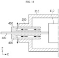
FIG. 13 is a cross-sectional view, taken along the axis b-b' ofFIG. 3 .FIG. 14 is a diagram showing the flow of gas generated in the battery cell and discharged to the outside inFIG. 13 . - Referring to
FIG. 13 , the end of the dentedportion 450 at the outermost side of thebattery case 200 may be located outer than the outer surface of thebattery case 200. In this specification, the outer surface of thebattery case 200 means an end of the sealingportion 250 of thebattery case 200 at an outer side of the battery. Accordingly, it may be easier to sufficiently secure an area through which the gas can be discharged to the outside of the battery. - In addition, the end of the dented
portion 450 that is opened toward the inside of thebattery case 200 may be located inner than the inner surface of thebattery case 200. In this specification, the inner surface of thebattery case 200 means an end of the sealingportion 250 of thebattery case 200 at an inner side of the battery. Accordingly, the gas in the battery may more easily flow into the dentedportion 450. - In the above case, the
lead film 400 may maximize the area of the dentedportion 450 so that the permeation area of the gas generated inside thebattery case 200 may be maximized, so a large amount of gas may be discharged. - Referring to
FIG. 13 , the thickness H of thelead film 400 surrounding the upper surface of the dentedportion 450 may be 100 µm to 300 µm, or 100 µm to 200 µm. If the thickness H of thelead film 400 surrounding the upper surface of the dentedportion 450 satisfies the above range, the gas inside thebattery case 200 may be more easily discharged to the outside. In this specification, thelead film 400 surrounding the upper surface of the dentedportion 450 refers to thelead film 400 between the dentedportion 450 and theelectrode lead 300. - Referring to
FIG. 13 , based on the protruding direction of theelectrode lead 300, the width W of thelead film 400 surrounding the front surface of the dentedportion 450 may be 2 mm or more, or 2 mm to 3 mm. In this specification, the width of thelead film 400 surrounding the front surface of the dentedportion 450 means a maximum value of the distance between the recessed end of thelead film 400 at the outermost side of thebattery case 200 and the end of thelead film 400 at the outer side of thebattery case 200. If the width W of thelead film 400 surrounding the front surface of the dentedportion 450 satisfies the above range, it may be easier to prevent thelead film 400 from being torn while the gas generated inside thebattery case 200 is discharged to the outside. - Referring to
FIG. 14 , the gas generated inside thebattery cell 100 may be discharged toward the dentedportion 450 of thelead film 400. Here, since the dentedportion 450 is opened toward the inside, the pressure inside the dentedportion 450 may be the same as the pressure inside thebattery case 200. - The pressure inside the dented
portion 450 is higher than the pressure outside thebattery cell 100, and the resulting pressure difference may act as a driving force of the gas. Accordingly, the gas introduced into the dentedportion 450 may be easily discharged toward the outside. In addition, the emission amount of gas generated inside thebattery cell 100 may also be increased. - At this time, the gas generated inside the
battery case 200 may be discharged along the Z-axis direction via the dentedportion 450 and thelead film 400 surrounding the upper surface of the dented portion. For example, when the dentedportion 450 is exposed to the outside of thebattery case 200, the gas generated inside thebattery case 200 may be discharged along the Z-axis direction via the dentedportion 450 and thelead film 400 surrounding the upper surface of the dented portion. In particular, when the recessed end of the dentedportion 450 at the outermost side of the battery case is located outer than the outer surface of thebattery case 200, gas may be discharged along the Z-axis direction through thelead film 400 between the recessed end the dentedportion 450 at the outermost side of thebattery case 200 and the outer surface of thebattery case 200. - In one embodiment of the present disclosure, the gas permeability of the
lead film 400 may be 20 Barrer to 60 Barrer, or 30 Barrer to 40 Barrer at 60°C. For example, the carbon dioxide permeability of thelead film 400 may satisfy the above range. In addition, the gas permeability may satisfy the above range at 60°C based on the thickness of thelead film 400 of 200 µm. If the gas permeability of thelead film 400 satisfies the above range, the gas generated inside the secondary battery may be more effectively discharged. - In this specification, the gas permeability may be measured by ASTM F2476-20.
- In one embodiment of the present disclosure, the moisture penetration amount of the
lead film 400 may be 0.02 g to 0.2 g, or 0.02 g to 0.04 g, or 0.06 g, or 0.15 g for 10 years at 25°C, 50 %RH. If the moisture penetration amount of thelead film 400 satisfies the above range, the penetration of moisture from thelead film 400 may be more effectively prevented. - The moisture penetration amount of the
lead film 400 may be measured by adopting the ASTM F 1249 method. At this time, the moisture penetration amount may be measured using equipment officially certified by MCOON. - In one embodiment of the present disclosure, the
lead film 400 may have a gas permeability of 20 Barrer to 60 Barrer at 60°C and a moisture penetration amount of 0.02 g to 0.2 g at 25°C, 50 %RH for 10 years. If the gas permeability and the moisture penetration amount of thelead film 400 satisfy the above ranges, the penetration of moisture from the outside may be more effectively prevented while discharging the gas generated inside the secondary battery. - In one embodiment of the present disclosure, the
lead film 400 may include a polyolefin-based resin. For example, thelead film 400 may include a polyolefin-based resin satisfying the gas permeability and/or moisture penetration amount values described above. The polyolefin-based resin may include at least one material selected from the group consisting of polypropylene, polyethylene, and polyvinyl difluoride (PVDF). While thelead film 400 contains polypropylene, the gas permeability of thelead film 400 may be 20 Barrer to 60 Barrer at 60°C. Also, the moisture penetration amount may be 0.06 g to 0.15 g. In this case, the gas generated inside the secondary battery may be more effectively discharged, and the penetration of moisture from the outside may be easily prevented. - In addition, since the
lead film 400 is made of the above-described material, thelead film 400 may maintain the airtightness of thebattery cell 100 and prevent leakage of the internal electrolytic solution. - A battery module according to another embodiment of the present disclosure includes the battery cell described above. Meanwhile, one or more battery modules according to this embodiment may be packaged in a pack case to form a battery pack.
- The battery module described above and the battery pack including the same may be applied to various devices. These devices may be transportation means such as electric bicycles, electric vehicles, hybrid electric vehicles, and the like, but the present disclosure is not limited thereto, and the present disclosure may be applied various devices that can use a battery module and a battery pack including the same, which is also within the scope of the right of the present disclosure.
- Although the preferred embodiment of the present disclosure has been described in detail above, the scope of the right of the present disclosure is not limited thereto, and various modifications and improvements made by those skilled in the art using the basic concept of the present disclosure defined in the appended claims also fall within the scope of the right of the present disclosure.
Claims (26)
- A battery cell, comprising:a battery case having an accommodation portion in which an electrode assembly is mounted, and a sealing portion formed by sealing an outer periphery thereof;an electrode lead electrically connected to an electrode tab included in the electrode assembly and protruding out of the battery case via the sealing portion; anda lead film located at a portion corresponding to the sealing portion in at least one of an upper portion and a lower portion of the electrode lead,wherein the lead film has a dented portion that is recessed in an outer direction of the battery case,the dented portion is opened toward the inside of the battery case,the dented portion includes a first dented portion and a second dented portion, anda width of the second dented portion is greater than a width of the first dented portion.
- The battery cell according to claim 1,
wherein the second dented portion is located farther from the accommodated electrode assembly than the first dented portion. - The battery cell according to claim 1,
wherein a part of the first dented portion is located at a position corresponding to the sealing portion. - The battery cell according to claim 1,
wherein a part of the second dented portion is located at a positon not corresponding to the sealing portion. - The battery cell according to claim 1,
wherein the lead film has a width greater than a width of the sealing portion and smaller than a length of the electrode lead. - The battery cell according to claim 5,
wherein the second dented portion is located between an end of the sealing portion and an end of the lead film. - The battery cell according to claim 1,wherein the first dented portion extends along a protruding direction of the electrode lead, andthe second dented portion extends along a longitudinal direction of the sealing portion.
- The battery cell according to claim 1,
wherein the second dented portion has a circular, triangular, rectangular or uneven shape. - The battery cell according to claim 1,
wherein an inner surface of the dented portion is closed based on a protruding direction of the electrode lead. - The battery cell according to claim 9,
wherein the lead film further includes an inner layer configured to cover at least one of inner surfaces of the dented portion. - The battery cell according to claim 10,
wherein a material of the inner layer has a higher melting point compared to a material of the lead film and does not react with an electrolytic solution. - The battery cell according to claim 1,
wherein the lead film contains a polyolefin-based material. - The battery cell according to claim 11,
wherein the inner layer contains at least one of polyolefin-based materials, fluorine-based materials and porous ceramic-based materials. - The battery cell according to claim 1,
wherein the dented portion is located over the electrode lead. - The battery cell according to claim 1,
wherein the lead film has a length greater than a width of the electrode lead. - The battery cell according to claim 15,
wherein the dented portion is located between an end of the electrode lead and an end of the lead film. - The battery cell according to claim 1,wherein the lead film includes a first lead film and a second lead film,the first lead film is located at an upper portion of the electrode lead, andthe second lead film is located at a lower portion of the electrode lead.
- The battery cell according to claim 17,
wherein the electrode lead is located between the first lead film and the second lead film, and the first lead film and the second lead film are connected to each other. - The battery cell according to claim 17,
wherein the dented portion is located in at least one of the first lead film and the second lead film. - The battery cell according to claim 1,
wherein an end of the dented portion at an outermost side of the battery case is located outer than an outer surface of the battery case. - The battery cell according to claim 1,
wherein an end of the dented portion opened toward the inside of the battery case is located inner than an inner surface of the battery case. - The battery cell according to claim 1,
wherein based on a protruding direction of the electrode lead, a width of the lead film surrounding a front surface of the dented portion is 2 mm or more. - The battery cell according to claim 1,
wherein a thickness of the lead film surrounding an upper surface of the dented portion is 100 µm to 300 µm. - The battery cell according to claim 1,
wherein the lead film has gas permeability of 20 Barrer to 60 Barrer at 60°C. - The battery cell according to claim 1,
wherein the lead film has a moisture penetration amount of 0.02 g to 0.2 g for 10 years at 25°C, 50 %RH. - A battery module, comprising the battery cell according to claim 1.
Applications Claiming Priority (2)
| Application Number | Priority Date | Filing Date | Title |
|---|---|---|---|
| KR20210016111 | 2021-02-04 | ||
| PCT/KR2022/001174 WO2022169146A1 (en) | 2021-02-04 | 2022-01-21 | Battery cell and battery module comprising same |
Publications (3)
| Publication Number | Publication Date |
|---|---|
| EP4187692A1 true EP4187692A1 (en) | 2023-05-31 |
| EP4187692A4 EP4187692A4 (en) | 2025-01-01 |
| EP4187692B1 EP4187692B1 (en) | 2026-01-21 |
Family
ID=82741381
Family Applications (1)
| Application Number | Title | Priority Date | Filing Date |
|---|---|---|---|
| EP22749900.1A Active EP4187692B1 (en) | 2021-02-04 | 2022-01-21 | Battery cell and battery module including the same |
Country Status (8)
| Country | Link |
|---|---|
| US (1) | US12482887B2 (en) |
| EP (1) | EP4187692B1 (en) |
| JP (2) | JP7508581B2 (en) |
| KR (2) | KR102562812B1 (en) |
| CN (2) | CN120657338A (en) |
| ES (1) | ES3062692T3 (en) |
| PL (1) | PL4187692T3 (en) |
| WO (1) | WO2022169146A1 (en) |
Families Citing this family (4)
| Publication number | Priority date | Publication date | Assignee | Title |
|---|---|---|---|---|
| KR102498916B1 (en) | 2022-02-14 | 2023-02-09 | 주식회사 엘지에너지솔루션 | Battery cell and battery module including the same |
| JPWO2024248106A1 (en) * | 2023-05-31 | 2024-12-05 | ||
| KR102785789B1 (en) * | 2023-08-11 | 2025-03-26 | 주식회사 엘지에너지솔루션 | Pouch cell and gas emission member |
| WO2026079652A1 (en) * | 2024-10-08 | 2026-04-16 | 주식회사 엘지에너지솔루션 | Electrode lead assembly and secondary battery |
Family Cites Families (18)
| Publication number | Priority date | Publication date | Assignee | Title |
|---|---|---|---|---|
| KR100684724B1 (en) | 2005-04-26 | 2007-02-20 | 삼성에스디아이 주식회사 | Secondary Battery and Safety Device Used in It |
| KR100959090B1 (en) * | 2007-12-18 | 2010-05-20 | 주식회사 엘지화학 | Pouch type secondary battery with improved safety |
| US20110033769A1 (en) | 2009-08-10 | 2011-02-10 | Kevin Huang | Electrical Storage Device Including Oxide-ion Battery Cell Bank and Module Configurations |
| KR101240753B1 (en) | 2011-07-06 | 2013-03-11 | 삼성에스디아이 주식회사 | Secondary battery |
| CN202150520U (en) | 2011-08-08 | 2012-02-22 | 海洋王照明科技股份有限公司 | Lithium ion battery |
| JP5969368B2 (en) | 2012-11-30 | 2016-08-17 | 昭和電工パッケージング株式会社 | Exterior body for electrochemical element |
| KR20140129600A (en) | 2013-04-30 | 2014-11-07 | 주식회사 엘지화학 | Secondary battery and Component for secondary battery applied for it |
| KR102188446B1 (en) * | 2014-04-22 | 2020-12-08 | 에스케이이노베이션 주식회사 | Pouch for secondary battery and secondary battery using the same |
| KR102318043B1 (en) * | 2015-04-22 | 2021-10-28 | 에스케이이노베이션 주식회사 | Secondary battery and battery module having the same |
| KR101904587B1 (en) * | 2015-09-01 | 2018-10-04 | 주식회사 엘지화학 | Battery cell and method for manufacturing the same |
| KR102066013B1 (en) * | 2016-02-17 | 2020-01-14 | 주식회사 엘지화학 | Rechargeable battery |
| US10141550B2 (en) | 2016-10-20 | 2018-11-27 | Ford Global Technologies, Llc | Pouch battery cell assembly for traction battery |
| KR102258822B1 (en) * | 2017-04-25 | 2021-06-07 | 주식회사 엘지에너지솔루션 | Reusable pouch type secondary battery, battery module comprising the same and method of reusing battery module |
| JP7136102B2 (en) | 2017-07-24 | 2022-09-13 | 大日本印刷株式会社 | Adhesive film for metal terminal, metal terminal with adhesive film for metal terminal, battery using said adhesive film for metal terminal, and method for manufacturing battery |
| KR102361569B1 (en) | 2018-04-23 | 2022-02-10 | 주식회사 엘지에너지솔루션 | Pouch Type Secondary Battery With Gas Venting Means |
| JP6780725B2 (en) | 2019-03-22 | 2020-11-04 | 大日本印刷株式会社 | Packaging container and batteries equipped with it |
| KR20220034036A (en) * | 2019-07-10 | 2022-03-17 | 다이니폰 인사츠 가부시키가이샤 | The adhesive film for metal terminals, the metal terminal with the adhesive film for metal terminals, the electrical storage device using the said adhesive film for metal terminals, and the manufacturing method of the electrical storage device |
| KR102813697B1 (en) | 2019-07-31 | 2025-05-28 | 삼성디스플레이 주식회사 | Display device |
-
2022
- 2022-01-21 CN CN202510833613.1A patent/CN120657338A/en active Pending
- 2022-01-21 ES ES22749900T patent/ES3062692T3/en active Active
- 2022-01-21 PL PL22749900.1T patent/PL4187692T3/en unknown
- 2022-01-21 JP JP2022563199A patent/JP7508581B2/en active Active
- 2022-01-21 KR KR1020220009551A patent/KR102562812B1/en active Active
- 2022-01-21 US US17/915,022 patent/US12482887B2/en active Active
- 2022-01-21 CN CN202280003610.XA patent/CN115461916B/en active Active
- 2022-01-21 EP EP22749900.1A patent/EP4187692B1/en active Active
- 2022-01-21 WO PCT/KR2022/001174 patent/WO2022169146A1/en not_active Ceased
-
2023
- 2023-07-27 KR KR1020230098456A patent/KR102645005B1/en active Active
-
2024
- 2024-06-17 JP JP2024097496A patent/JP7804723B2/en active Active
Also Published As
| Publication number | Publication date |
|---|---|
| PL4187692T3 (en) | 2026-04-20 |
| JP2024116376A (en) | 2024-08-27 |
| ES3062692T3 (en) | 2026-04-13 |
| KR20230118535A (en) | 2023-08-11 |
| KR102645005B1 (en) | 2024-03-07 |
| KR102562812B1 (en) | 2023-08-02 |
| CN120657338A (en) | 2025-09-16 |
| KR20220112682A (en) | 2022-08-11 |
| EP4187692A4 (en) | 2025-01-01 |
| JP7508581B2 (en) | 2024-07-01 |
| CN115461916B (en) | 2025-07-11 |
| US12482887B2 (en) | 2025-11-25 |
| EP4187692B1 (en) | 2026-01-21 |
| JP7804723B2 (en) | 2026-01-22 |
| US20230163386A1 (en) | 2023-05-25 |
| JP2023522347A (en) | 2023-05-30 |
| CN115461916A (en) | 2022-12-09 |
| WO2022169146A1 (en) | 2022-08-11 |
Similar Documents
| Publication | Publication Date | Title |
|---|---|---|
| EP4195379A1 (en) | Battery cell, manufacturing method therefor, and battery module comprising same | |
| EP4187692B1 (en) | Battery cell and battery module including the same | |
| EP4191761B1 (en) | Battery cell and battery cell manufacturing apparatus | |
| EP4170804A1 (en) | Battery cell and battery module including same | |
| US12603366B2 (en) | Battery cell and battery module including the same | |
| EP4178015B1 (en) | Battery cell and battery module including same | |
| EP4203149A1 (en) | Battery cell and battery module including same | |
| EP4195377A1 (en) | Battery cell and battery module comprising same | |
| US12614790B2 (en) | Battery cell and battery module comprising same | |
| EP4195378B1 (en) | Battery cell and battery cell manufacturing apparatus | |
| EP4106090B1 (en) | Battery cell and battery module including the same | |
| EP4391186B1 (en) | Battery cell and battery module comprising same |
Legal Events
| Date | Code | Title | Description |
|---|---|---|---|
| STAA | Information on the status of an ep patent application or granted ep patent |
Free format text: STATUS: THE INTERNATIONAL PUBLICATION HAS BEEN MADE |
|
| PUAI | Public reference made under article 153(3) epc to a published international application that has entered the european phase |
Free format text: ORIGINAL CODE: 0009012 |
|
| STAA | Information on the status of an ep patent application or granted ep patent |
Free format text: STATUS: REQUEST FOR EXAMINATION WAS MADE |
|
| 17P | Request for examination filed |
Effective date: 20230224 |
|
| AK | Designated contracting states |
Kind code of ref document: A1 Designated state(s): AL AT BE BG CH CY CZ DE DK EE ES FI FR GB GR HR HU IE IS IT LI LT LU LV MC MK MT NL NO PL PT RO RS SE SI SK SM TR |
|
| DAV | Request for validation of the european patent (deleted) | ||
| DAX | Request for extension of the european patent (deleted) | ||
| A4 | Supplementary search report drawn up and despatched |
Effective date: 20241204 |
|
| RIC1 | Information provided on ipc code assigned before grant |
Ipc: H01M 50/211 20210101ALI20241128BHEP Ipc: H01M 50/342 20210101ALI20241128BHEP Ipc: H01M 50/178 20210101ALI20241128BHEP Ipc: H01M 50/193 20210101ALI20241128BHEP Ipc: H01M 50/198 20210101ALI20241128BHEP Ipc: H01M 50/186 20210101ALI20241128BHEP Ipc: H01M 50/105 20210101ALI20241128BHEP Ipc: H01M 50/184 20210101AFI20241128BHEP |
|
| STAA | Information on the status of an ep patent application or granted ep patent |
Free format text: STATUS: EXAMINATION IS IN PROGRESS |
|
| 17Q | First examination report despatched |
Effective date: 20250408 |
|
| GRAP | Despatch of communication of intention to grant a patent |
Free format text: ORIGINAL CODE: EPIDOSNIGR1 |
|
| STAA | Information on the status of an ep patent application or granted ep patent |
Free format text: STATUS: GRANT OF PATENT IS INTENDED |
|
| INTG | Intention to grant announced |
Effective date: 20250806 |
|
| P01 | Opt-out of the competence of the unified patent court (upc) registered |
Free format text: CASE NUMBER: UPC_APP_6745_4187692/2025 Effective date: 20250911 |
|
| GRAS | Grant fee paid |
Free format text: ORIGINAL CODE: EPIDOSNIGR3 |
|
| GRAA | (expected) grant |
Free format text: ORIGINAL CODE: 0009210 |
|
| STAA | Information on the status of an ep patent application or granted ep patent |
Free format text: STATUS: THE PATENT HAS BEEN GRANTED |
|
| AK | Designated contracting states |
Kind code of ref document: B1 Designated state(s): AL AT BE BG CH CY CZ DE DK EE ES FI FR GB GR HR HU IE IS IT LI LT LU LV MC MK MT NL NO PL PT RO RS SE SI SK SM TR |
|
| REG | Reference to a national code |
Ref country code: CH Ref legal event code: F10 Free format text: ST27 STATUS EVENT CODE: U-0-0-F10-F00 (AS PROVIDED BY THE NATIONAL OFFICE) Effective date: 20260121 |
|
| REG | Reference to a national code |
Ref country code: DE Ref legal event code: R096 Ref document number: 602022028885 Country of ref document: DE |
|
| REG | Reference to a national code |
Ref country code: IE Ref legal event code: FG4D |
|
| PGFP | Annual fee paid to national office [announced via postgrant information from national office to epo] |
Ref country code: HU Payment date: 20260227 Year of fee payment: 5 |
|
| PGFP | Annual fee paid to national office [announced via postgrant information from national office to epo] |
Ref country code: SE Payment date: 20260206 Year of fee payment: 5 |
|
| PGFP | Annual fee paid to national office [announced via postgrant information from national office to epo] |
Ref country code: GB Payment date: 20260209 Year of fee payment: 5 |
|
| PGFP | Annual fee paid to national office [announced via postgrant information from national office to epo] |
Ref country code: ES Payment date: 20260324 Year of fee payment: 5 |
|
| PGFP | Annual fee paid to national office [announced via postgrant information from national office to epo] |
Ref country code: DE Payment date: 20260205 Year of fee payment: 5 |
|
| REG | Reference to a national code |
Ref country code: ES Ref legal event code: FG2A Ref document number: 3062692 Country of ref document: ES Kind code of ref document: T3 Effective date: 20260413 |
|
| PGFP | Annual fee paid to national office [announced via postgrant information from national office to epo] |
Ref country code: AT Payment date: 20260301 Year of fee payment: 5 |
|
| PGFP | Annual fee paid to national office [announced via postgrant information from national office to epo] |
Ref country code: BE Payment date: 20260206 Year of fee payment: 5 |
|
| PGFP | Annual fee paid to national office [announced via postgrant information from national office to epo] |
Ref country code: FR Payment date: 20260209 Year of fee payment: 5 |