EP4187691A1 - Secondary battery having vent unit formed on insulation film and manufacturing method therefor - Google Patents
Secondary battery having vent unit formed on insulation film and manufacturing method therefor Download PDFInfo
- Publication number
- EP4187691A1 EP4187691A1 EP22746267.8A EP22746267A EP4187691A1 EP 4187691 A1 EP4187691 A1 EP 4187691A1 EP 22746267 A EP22746267 A EP 22746267A EP 4187691 A1 EP4187691 A1 EP 4187691A1
- Authority
- EP
- European Patent Office
- Prior art keywords
- negative electrode
- positive electrode
- insulation film
- electrode lead
- lead
- Prior art date
- Legal status (The legal status is an assumption and is not a legal conclusion. Google has not performed a legal analysis and makes no representation as to the accuracy of the status listed.)
- Granted
Links
Images

Classifications
-
- H—ELECTRICITY
- H01—ELECTRIC ELEMENTS
- H01M—PROCESSES OR MEANS, e.g. BATTERIES, FOR THE DIRECT CONVERSION OF CHEMICAL ENERGY INTO ELECTRICAL ENERGY
- H01M50/00—Constructional details or processes of manufacture of the non-active parts of electrochemical cells other than fuel cells, e.g. hybrid cells
- H01M50/10—Primary casings; Jackets or wrappings
- H01M50/172—Arrangements of electric connectors penetrating the casing
- H01M50/174—Arrangements of electric connectors penetrating the casing adapted for the shape of the cells
- H01M50/178—Arrangements of electric connectors penetrating the casing adapted for the shape of the cells for pouch or flexible bag cells
-
- H—ELECTRICITY
- H01—ELECTRIC ELEMENTS
- H01M—PROCESSES OR MEANS, e.g. BATTERIES, FOR THE DIRECT CONVERSION OF CHEMICAL ENERGY INTO ELECTRICAL ENERGY
- H01M50/00—Constructional details or processes of manufacture of the non-active parts of electrochemical cells other than fuel cells, e.g. hybrid cells
- H01M50/10—Primary casings; Jackets or wrappings
- H01M50/172—Arrangements of electric connectors penetrating the casing
-
- H—ELECTRICITY
- H01—ELECTRIC ELEMENTS
- H01M—PROCESSES OR MEANS, e.g. BATTERIES, FOR THE DIRECT CONVERSION OF CHEMICAL ENERGY INTO ELECTRICAL ENERGY
- H01M50/00—Constructional details or processes of manufacture of the non-active parts of electrochemical cells other than fuel cells, e.g. hybrid cells
- H01M50/10—Primary casings; Jackets or wrappings
- H01M50/183—Sealing members
- H01M50/184—Sealing members characterised by their shape or structure
-
- H—ELECTRICITY
- H01—ELECTRIC ELEMENTS
- H01M—PROCESSES OR MEANS, e.g. BATTERIES, FOR THE DIRECT CONVERSION OF CHEMICAL ENERGY INTO ELECTRICAL ENERGY
- H01M50/00—Constructional details or processes of manufacture of the non-active parts of electrochemical cells other than fuel cells, e.g. hybrid cells
- H01M50/10—Primary casings; Jackets or wrappings
- H01M50/183—Sealing members
- H01M50/186—Sealing members characterised by the disposition of the sealing members
-
- H—ELECTRICITY
- H01—ELECTRIC ELEMENTS
- H01M—PROCESSES OR MEANS, e.g. BATTERIES, FOR THE DIRECT CONVERSION OF CHEMICAL ENERGY INTO ELECTRICAL ENERGY
- H01M50/00—Constructional details or processes of manufacture of the non-active parts of electrochemical cells other than fuel cells, e.g. hybrid cells
- H01M50/10—Primary casings; Jackets or wrappings
- H01M50/183—Sealing members
- H01M50/19—Sealing members characterised by the material
- H01M50/191—Inorganic material
-
- H—ELECTRICITY
- H01—ELECTRIC ELEMENTS
- H01M—PROCESSES OR MEANS, e.g. BATTERIES, FOR THE DIRECT CONVERSION OF CHEMICAL ENERGY INTO ELECTRICAL ENERGY
- H01M50/00—Constructional details or processes of manufacture of the non-active parts of electrochemical cells other than fuel cells, e.g. hybrid cells
- H01M50/10—Primary casings; Jackets or wrappings
- H01M50/183—Sealing members
- H01M50/19—Sealing members characterised by the material
- H01M50/193—Organic material
-
- H—ELECTRICITY
- H01—ELECTRIC ELEMENTS
- H01M—PROCESSES OR MEANS, e.g. BATTERIES, FOR THE DIRECT CONVERSION OF CHEMICAL ENERGY INTO ELECTRICAL ENERGY
- H01M50/00—Constructional details or processes of manufacture of the non-active parts of electrochemical cells other than fuel cells, e.g. hybrid cells
- H01M50/30—Arrangements for facilitating escape of gases
-
- H—ELECTRICITY
- H01—ELECTRIC ELEMENTS
- H01M—PROCESSES OR MEANS, e.g. BATTERIES, FOR THE DIRECT CONVERSION OF CHEMICAL ENERGY INTO ELECTRICAL ENERGY
- H01M50/00—Constructional details or processes of manufacture of the non-active parts of electrochemical cells other than fuel cells, e.g. hybrid cells
- H01M50/30—Arrangements for facilitating escape of gases
- H01M50/342—Non-re-sealable arrangements
- H01M50/3425—Non-re-sealable arrangements in the form of rupturable membranes or weakened parts, e.g. pierced with the aid of a sharp member
-
- H—ELECTRICITY
- H01—ELECTRIC ELEMENTS
- H01M—PROCESSES OR MEANS, e.g. BATTERIES, FOR THE DIRECT CONVERSION OF CHEMICAL ENERGY INTO ELECTRICAL ENERGY
- H01M50/00—Constructional details or processes of manufacture of the non-active parts of electrochemical cells other than fuel cells, e.g. hybrid cells
- H01M50/30—Arrangements for facilitating escape of gases
- H01M50/394—Gas-pervious parts or elements
-
- H—ELECTRICITY
- H01—ELECTRIC ELEMENTS
- H01M—PROCESSES OR MEANS, e.g. BATTERIES, FOR THE DIRECT CONVERSION OF CHEMICAL ENERGY INTO ELECTRICAL ENERGY
- H01M50/00—Constructional details or processes of manufacture of the non-active parts of electrochemical cells other than fuel cells, e.g. hybrid cells
- H01M50/50—Current conducting connections for cells or batteries
- H01M50/531—Electrode connections inside a battery casing
- H01M50/533—Electrode connections inside a battery casing characterised by the shape of the leads or tabs
-
- H—ELECTRICITY
- H01—ELECTRIC ELEMENTS
- H01M—PROCESSES OR MEANS, e.g. BATTERIES, FOR THE DIRECT CONVERSION OF CHEMICAL ENERGY INTO ELECTRICAL ENERGY
- H01M50/00—Constructional details or processes of manufacture of the non-active parts of electrochemical cells other than fuel cells, e.g. hybrid cells
- H01M50/50—Current conducting connections for cells or batteries
- H01M50/543—Terminals
- H01M50/552—Terminals characterised by their shape
- H01M50/553—Terminals adapted for prismatic, pouch or rectangular cells
- H01M50/557—Plate-shaped terminals
-
- H—ELECTRICITY
- H01—ELECTRIC ELEMENTS
- H01M—PROCESSES OR MEANS, e.g. BATTERIES, FOR THE DIRECT CONVERSION OF CHEMICAL ENERGY INTO ELECTRICAL ENERGY
- H01M2220/00—Batteries for particular applications
- H01M2220/30—Batteries in portable systems, e.g. mobile phone, laptop
-
- Y—GENERAL TAGGING OF NEW TECHNOLOGICAL DEVELOPMENTS; GENERAL TAGGING OF CROSS-SECTIONAL TECHNOLOGIES SPANNING OVER SEVERAL SECTIONS OF THE IPC; TECHNICAL SUBJECTS COVERED BY FORMER USPC CROSS-REFERENCE ART COLLECTIONS [XRACs] AND DIGESTS
- Y02—TECHNOLOGIES OR APPLICATIONS FOR MITIGATION OR ADAPTATION AGAINST CLIMATE CHANGE
- Y02E—REDUCTION OF GREENHOUSE GAS [GHG] EMISSIONS, RELATED TO ENERGY GENERATION, TRANSMISSION OR DISTRIBUTION
- Y02E60/00—Enabling technologies; Technologies with a potential or indirect contribution to GHG emissions mitigation
- Y02E60/10—Energy storage using batteries
-
- Y—GENERAL TAGGING OF NEW TECHNOLOGICAL DEVELOPMENTS; GENERAL TAGGING OF CROSS-SECTIONAL TECHNOLOGIES SPANNING OVER SEVERAL SECTIONS OF THE IPC; TECHNICAL SUBJECTS COVERED BY FORMER USPC CROSS-REFERENCE ART COLLECTIONS [XRACs] AND DIGESTS
- Y02—TECHNOLOGIES OR APPLICATIONS FOR MITIGATION OR ADAPTATION AGAINST CLIMATE CHANGE
- Y02P—CLIMATE CHANGE MITIGATION TECHNOLOGIES IN THE PRODUCTION OR PROCESSING OF GOODS
- Y02P70/00—Climate change mitigation technologies in the production process for final industrial or consumer products
- Y02P70/50—Manufacturing or production processes characterised by the final manufactured product
Definitions
- the present disclosure relates to a secondary battery having a vent portion formed on an insulation film and a method for manufacturing the same.
- a typical example of electrochemical devices using electrochemical energy includes a secondary battery, and the area of the use of secondary batteries is gradually expanding.
- lithium secondary batteries which show high charge/discharge characteristics and life characteristics and are eco-friendly have been studied intensively, and have been commercialized and used widely.
- lithium secondary batteries cause an increase in gases generated inside of the secondary batteries due to such increased energy density.
- the present disclosure is designed to solve the problems of the related art.
- the present disclosure is directed to providing a secondary battery having improved safety by structuralizing a gas discharge path efficiently through a simpler method to release gases to the outside efficiently, while minimizing water diffused from the outside, and a method for manufacturing the secondary battery.
- a secondary battery which includes an electrode assembly including a positive electrode, a negative electrode and a separator interposed between the positive electrode and the negative electrode, and received in a battery casing together with an electrolyte,
- the vent portion may be a coating layer formed by transferring a non-adhesive material from a roll onto the insulation film through roll pressing.
- the non-adhesive material may be a material cured after coating a polymer having a melting point of 220°C or higher, or gelled ceramic particles, and particularly, may be a material cured after coating at least one polymer selected from the group consisting of a polyimide-based material, polytetrafluoroethylene and polymethyl pentene, or at least one ceramic particle selected from the group consisting of SiOz, TiOz, ZnO, CaO and BaO in a gelled state.
- vent portion has a planar shape selected from a circular shape, an oval shape and a polygonal shape.
- At least one electrode lead of the positive electrode lead and the negative electrode lead may include a metal substrate and a coating layer formed on the surface of the metal substrate.
- a method for manufacturing the secondary battery including the steps of:
- the non-adhesive material may be a material cured after coating a polymer having a melting point of 220°C or higher, or gelled ceramic particles, and particularly, may be a material cured after coating at least one polymer selected from the group consisting of a polyimide-based material, polytetrafluoroethylene and polymethyl pentene, or at least one ceramic particle selected from the group consisting of SiOz, TiOz, ZnO, CaO and BaO in a gelled state.
- vent portion has a planar shape selected from a circular shape, an oval shape and a polygonal shape.
- a gas discharge path may be formed on a lead portion by forming a vent portion on the insulation film attached to an electrode lead, thereby providing an increased effective value.
- vent film is formed through a simplified method of coating a non-adhesive material on the insulation film adhered with the electrode lead through a roll pressing process, and thus can be formed rapidly and efficiently.
- a secondary battery which includes an electrode assembly including a positive electrode, a negative electrode and a separator interposed between the positive electrode and the negative electrode, and received in a battery casing together with an electrolyte,
- the secondary battery cannot be used any longer, once it is vented. Therefore, the life of the secondary battery is reduced significantly, or a separate member is required additionally, and thus the methods cannot have an edge in price competitiveness.
- a vent portion is formed in an electrode lead portion through a simpler method, and thus it is possible to improve the life of the secondary battery significantly, while ensuring the safety of the secondary battery.
- the vent portion can be formed through a very simple and inexpensive process.
- the vent portion may be formed by using any method known to those skilled in the art with no particular limitation. For example, spin coating, blade coating, spray coating and ink jet printing processes may be used. Particularly, the vent portion may be a coating layer formed by transferring a non-adhesive material from a roll onto an insulation film through roll pressing.
- the vent portion may be formed in a very simple manner by forming a coating layer of non-adhesive material on the insulation film adhered with the lead, and attaching the insulation film to the lead in such a manner that the coating layer may be interposed between the lead and the insulation film, in a significantly efficient manner in terms of process and cost.
- the non-adhesive material refers to a material which is not adhered with the positive electrode lead or negative electrode lead subsequently.
- the non-adhesive material may be a material cured after coating a polymer having a melting point of 220°C or higher, or gelled ceramic particles, and particularly, may be a material cured after coating at least one polymer selected from the group consisting of a polyimide-based material, polytetrafluoroethylene and polymethyl pentene, or at least one ceramic particle selected from the group consisting of SiOz, TiOz, ZnO, CaO and BaO in a gelled state.
- the non-adhesive material may be formed with a coating thickness of 30 nm to 1 mm.
- the coating thickness of the non-adhesive material satisfies the above-defined range, there is an advantage in terms of process, and it is possible to prevent a problem in which portions except the non-adhesive material are not sealed. Therefore, it is possible to easily prevent a problem of electrolyte leakage.
- the vent portion may be formed with an area of 10-70%, particularly 20-50%, based on the total area where the positive electrode lead is attached to the positive electrode insulation film, or the negative electrode lead is attached to the negative electrode insulation film.
- the vent portion is not particularly limited in terms of its planar shape, and may have various forms, such as a circular shape, an oval shape and a polygonal shape, with the proviso that it may be formed with a pattern capable of preventing a problem, such as electrolyte leakage, and discharging gases efficiently.
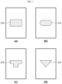
- FIG. 1 is a schematic view illustrating some embodiments of the shape of a vent portion 101 on the insulation film 100.
- FIG. 1(a) illustrates a rectangular vent portion
- FIG. 1(b) illustrates an oval vent portion
- FIG. 1(c) illustrates an irregularity-like polygonal vent portion
- FIG. 1(d) illustrates a triangular vent portion 101.
- FIG. 2 is a schematic view illustrating the secondary battery 200 according to an embodiment of the present disclosure.
- an electrode assembly 201 including a positive electrode, a negative electrode and a separator interposed between the positive electrode and the negative electrode is received in a battery casing 202 together with an electrolyte, wherein the positive electrode includes a positive electrode tab 203, the negative electrode includes a negative electrode tab 204, the positive electrode tab 203 is connected electrically to a positive electrode lead 205, the negative electrode tab 204 is connected electrically to a negative electrode lead 206, the positive electrode lead 205 and the negative electrode lead 206 are exposed to the outside through a sealing portion of the battery casing, each of a positive electrode insulation film 110 and a negative electrode insulation film 100 is attached to a portion where each of the positive electrode lead 205 and the negative electrode lead 206 is in contact with the sealing portion of the battery casing 202.
- the vent portion 101 is disposed between the negative electrode insulation film 100 and the negative electrode lead 206 and is not adhered with the negative electrode lead 206, and thus functions as a gas discharge path.
- a vent portion may be formed in the positive electrode insulation film 110, or may be formed in both of the positive electrode insulation film 110 and the negative electrode insulation film 100.
- vent portion 101 may be formed with an area of 20-90%, particularly 30-80%, based on the area where the negative electrode lead 206 is in contact with the negative electrode insulation film 100.
- the area of the vent portion 101 satisfies the above-defined range, it is possible to ensure a sufficient area for the adhesion of the lead with the insulation film, while ensuring a vent effect, and thus to ensure sealability with ease.
- vent portion is the same as described hereinabove.
- the positive electrode insulation film 110 and the negative electrode insulation film 100 may be made of any one material selected from electrically insulating thermoplastic, thermosetting and photocurable resins.
- Particular examples of the material include polyolefin resin, styrene butadiene resin, styrene resin, epoxy resin, urethane resin, acrylic resin, phenolic resin, amide-based resin, acrylate resin and modified resin thereof, but the material is not particularly limited, as long as it can perform the above-described functions.
- At least one electrode lead of the positive electrode lead 205 and the negative electrode lead 206 may be made of a metal substrate, but may include the metal substrate and a coating layer formed on the surface of the metal substrate.
- the metal substrate may include at least one selected from the group consisting of nickel (Ni), aluminum (Al), copper (Cu) and stainless steel.
- a preferred material for the metal substrate may be different depending on whether the electrode lead is a positive electrode lead or a negative electrode lead.
- the metal substrate may include aluminum, nickel or alloy containing at least one of them.
- the metal substrate may include copper, nickel or alloy containing at least one of them.
- the coating layer is used to prevent the electrode lead from corrosion caused by a strong acid generated by the reaction between water infiltrating to the secondary battery and an electrolyte, while improving the adhesion between the electrode lead and the insulation film.
- the coating layer may include a metal or metal oxide, and particularly, may include at least one selected from the group consisting of chrome (Cr), nickel (Ni), iron (Fe), molybdenum (Mo), silicon (Si), titanium (Ti), columbium (Cb), silicon oxide, tin oxide and titanium oxide.
- the coating layer may have a thickness of 100 ⁇ m or less, particularly 30-100 ⁇ m, more particularly 30-80 ⁇ m, and most particularly 30-70 ⁇ m.
- the coating layer may be formed by using a method well known to those skilled in the art with no particular limitation.
- the coating layer may be formed by electroplating, or the like.
- the battery casing is not particularly limited, it may be a pouch-type battery casing which allows suitable application of the above-described structure.
- a method for manufacturing the secondary battery including the steps of:
- the vent portion may be formed by a roll pressing process.
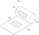
- the method is shown schematically in FIG.3 .
- a roll 300 having a non-adhesive material 111 corresponding to the shape of a vent portion 101 formed on the surface thereof is used to carry out pressing so that the non-adhesive material 111 may be transferred to and coated on the surface of the insulation film 100, thereby forming a vent portion 101.
- the shape of the vent portion 101 is a rectangular shape.
- the vent portion may have a planar shape selected from a circular shape, an oval shape and a polygonal shape with no particular limitation.
Landscapes
- Chemical & Material Sciences (AREA)
- Chemical Kinetics & Catalysis (AREA)
- Electrochemistry (AREA)
- General Chemical & Material Sciences (AREA)
- Inorganic Chemistry (AREA)
- Connection Of Batteries Or Terminals (AREA)
- Sealing Battery Cases Or Jackets (AREA)
- Gas Exhaust Devices For Batteries (AREA)
- Secondary Cells (AREA)
Abstract
Description
- The present application claims priority to
Korean Patent Application No. 10-2021-0011775 filed on January 27, 2021 - The present disclosure relates to a secondary battery having a vent portion formed on an insulation film and a method for manufacturing the same.
- Due to the rapid increase in the use of fossil fuels, the demand for the use of alternative energy or clean energy is increasing, and the most actively studied filed as a part thereof is the field of power generation and power storage using electrochemistry.
- Currently, a typical example of electrochemical devices using electrochemical energy includes a secondary battery, and the area of the use of secondary batteries is gradually expanding.
- Recently, as technical development and demand for mobile instruments, such as portable computers, cellular phones and cameras, have been increased, secondary batteries as energy sources have been increasingly in demand. Particularly, lithium secondary batteries which show high charge/discharge characteristics and life characteristics and are eco-friendly have been studied intensively, and have been commercialized and used widely.
- However, as the application spectrum of lithium secondary batteries has been expanded as mentioned above, there is a need for an increase in energy density. Therefore, such lithium secondary batteries cause an increase in gases generated inside of the secondary batteries due to such increased energy density.
- Moreover, when water infiltrates into secondary batteries, side reactions occur, and thus the problems of degradation of the performance of secondary batteries and gas generation are accelerated undesirably.
- Under these circumstances, the above-mentioned safety problem has been solved by forming a vent portion in a secondary battery so that the gases generated inside of the secondary battery may be released to the outside. However, when the secondary battery is vented, the life of the secondary battery is reduced significantly. Therefore, there is an imminent need for the solution of the above-mentioned problem.
- The present disclosure is designed to solve the problems of the related art.
- Particularly, the present disclosure is directed to providing a secondary battery having improved safety by structuralizing a gas discharge path efficiently through a simpler method to release gases to the outside efficiently, while minimizing water diffused from the outside, and a method for manufacturing the secondary battery.
- In one aspect of the present disclosure, there is provided a secondary battery which includes an electrode assembly including a positive electrode, a negative electrode and a separator interposed between the positive electrode and the negative electrode, and received in a battery casing together with an electrolyte,
- wherein the positive electrode includes a positive electrode tab, and the negative electrode includes a negative electrode tab,
- the positive electrode tab is connected electrically to a positive electrode lead, the negative electrode tab is connected electrically to a negative electrode lead, and the positive electrode lead and the negative electrode lead are exposed to the outside through a sealing portion of the battery casing,
- each of a positive electrode insulation film and a negative electrode insulation film is attached to a portion where each of the positive electrode lead and the negative electrode lead is in contact with the sealing portion of the battery casing, and
- at least one insulation film of the positive electrode insulation film and the negative electrode insulation film has a vent portion surface-treated with a non-adhesive material between the insulation film and the positive electrode lead or the negative electrode lead, at the portion where the positive electrode lead or the negative electrode lead is attached.
- Herein, the vent portion may be a coating layer formed by transferring a non-adhesive material from a roll onto the insulation film through roll pressing.
- The non-adhesive material may be a material cured after coating a polymer having a melting point of 220°C or higher, or gelled ceramic particles, and particularly, may be a material cured after coating at least one polymer selected from the group consisting of a polyimide-based material, polytetrafluoroethylene and polymethyl pentene, or at least one ceramic particle selected from the group consisting of SiOz, TiOz, ZnO, CaO and BaO in a gelled state.
- In addition, the vent portion has a planar shape selected from a circular shape, an oval shape and a polygonal shape.
- Meanwhile, at least one electrode lead of the positive electrode lead and the negative electrode lead may include a metal substrate and a coating layer formed on the surface of the metal substrate.
- In another aspect of the present disclosure, there is provided a method for manufacturing the secondary battery, including the steps of:
- (a) preparing at least one positive electrode and at least one negative electrode each having a structure including an electrode active material layer formed on a current collector having a tab formed in at least one side thereof;
- (b) interposing a separator between the positive electrode and the negative electrode;
- (c) transferring a non-adhesive material to at least one of a positive electrode insulation film and a negative electrode insulation film through a roll pressing process by using a roll including the non-adhesive material corresponding to the shape of a vent portion, thereby forming a vent portion; and
- (d) connecting the positive electrode lead electrically to the positive electrode tab and connecting the negative electrode lead electrically to the negative electrode tab, and attaching the positive electrode insulation film and the negative electrode insulation film to the positive electrode lead and the negative electrode lead, respectively,
wherein the vent portion is interposed between the positive electrode lead and the portion to which the positive electrode insulation film is attached, between the negative electrode lead and the portion to which the negative electrode insulation film is attached, or both. - Herein, the non-adhesive material may be a material cured after coating a polymer having a melting point of 220°C or higher, or gelled ceramic particles, and particularly, may be a material cured after coating at least one polymer selected from the group consisting of a polyimide-based material, polytetrafluoroethylene and polymethyl pentene, or at least one ceramic particle selected from the group consisting of SiOz, TiOz, ZnO, CaO and BaO in a gelled state.
- In addition, the vent portion has a planar shape selected from a circular shape, an oval shape and a polygonal shape.
- According to an embodiment of the present disclosure, a gas discharge path may be formed on a lead portion by forming a vent portion on the insulation film attached to an electrode lead, thereby providing an increased effective value.
- In addition, the vent film is formed through a simplified method of coating a non-adhesive material on the insulation film adhered with the electrode lead through a roll pressing process, and thus can be formed rapidly and efficiently.
-
-
FIG. 1 is a schematic view illustrating some embodiments of the shape of a vent portion formed on an insulation film according to an embodiment of the present disclosure. -
FIG. 2 is a schematic view illustrating the secondary battery according to another embodiment of the present disclosure. -
FIG. 3 is a schematic view illustrating the method for forming a vent portion according to still another embodiment of the present disclosure. - Hereinafter, preferred embodiments of the present disclosure will be described in detail with reference to the accompanying drawings.
- Prior to the description, it should be understood that the terms used in the specification and the appended claims should not be construed as limited to general and dictionary meanings, but interpreted based on the meanings and concepts corresponding to technical aspects of the present disclosure on the basis of the principle that the inventor is allowed to define terms appropriately for the best explanation.
- The terminology used herein is for the purpose of describing particular embodiments only and is not intended to be limiting of the present disclosure. As used herein, the singular forms "a", "an" and "the" are intended to include the plural forms as well, unless the context clearly indicates otherwise.
- It will be understood that the terms "include", "is provided with" or "have" when used in this specification, refer to the presence of any stated features, numbers, steps, elements and/or combinations thereof, but do not preclude the addition of one or more other features, numbers, steps, elements and/or combinations thereof.
- In one aspect of the present disclosure, there is provided a secondary battery which includes an electrode assembly including a positive electrode, a negative electrode and a separator interposed between the positive electrode and the negative electrode, and received in a battery casing together with an electrolyte,
- wherein the positive electrode includes a positive electrode tab, and the negative electrode includes a negative electrode tab,
- the positive electrode tab is connected electrically to a positive electrode lead, the negative electrode tab is connected electrically to a negative electrode lead, and the positive electrode lead and the negative electrode lead are exposed to the outside through a sealing portion of the battery casing,
- each of a positive electrode insulation film and a negative electrode insulation film is attached to a portion where each of the positive electrode lead and the negative electrode lead is in contact with the sealing portion of the battery casing, and
- at least one insulation film of the positive electrode insulation film and the negative electrode insulation film has a vent portion surface-treated with a non-adhesive material between the insulation film and the positive electrode lead or the negative electrode lead, at the portion where the positive electrode lead or the negative electrode lead is attached.
- According to the related art, various methods have been developed to discharge gases generated inside of a secondary battery to the outside, when such gases are generated. For example, there have been attempts to ensure the safety of a secondary battery by discharging the gases generated inside of a secondary battery to the outside through the formation of a notch in a pouch, formation of a separate gas discharge member in a gap with a lead portion, or the like.
- However, according to the above-mentioned methods, the secondary battery cannot be used any longer, once it is vented. Therefore, the life of the secondary battery is reduced significantly, or a separate member is required additionally, and thus the methods cannot have an edge in price competitiveness.
- On the contrary, according to the present disclosure, a vent portion is formed in an electrode lead portion through a simpler method, and thus it is possible to improve the life of the secondary battery significantly, while ensuring the safety of the secondary battery.
- Particularly, the vent portion can be formed through a very simple and inexpensive process.
- For example, the vent portion may be formed by using any method known to those skilled in the art with no particular limitation. For example, spin coating, blade coating, spray coating and ink jet printing processes may be used. Particularly, the vent portion may be a coating layer formed by transferring a non-adhesive material from a roll onto an insulation film through roll pressing.
- The vent portion may be formed in a very simple manner by forming a coating layer of non-adhesive material on the insulation film adhered with the lead, and attaching the insulation film to the lead in such a manner that the coating layer may be interposed between the lead and the insulation film, in a significantly efficient manner in terms of process and cost.
- Herein, the non-adhesive material refers to a material which is not adhered with the positive electrode lead or negative electrode lead subsequently. For example, the non-adhesive material may be a material cured after coating a polymer having a melting point of 220°C or higher, or gelled ceramic particles, and particularly, may be a material cured after coating at least one polymer selected from the group consisting of a polyimide-based material, polytetrafluoroethylene and polymethyl pentene, or at least one ceramic particle selected from the group consisting of SiOz, TiOz, ZnO, CaO and BaO in a gelled state.
- Herein, the non-adhesive material may be formed with a coating thickness of 30 nm to 1 mm.
- When the coating thickness of the non-adhesive material satisfies the above-defined range, there is an advantage in terms of process, and it is possible to prevent a problem in which portions except the non-adhesive material are not sealed. Therefore, it is possible to easily prevent a problem of electrolyte leakage.
- Herein, the vent portion may be formed with an area of 10-70%, particularly 20-50%, based on the total area where the positive electrode lead is attached to the positive electrode insulation film, or the negative electrode lead is attached to the negative electrode insulation film.
- When the area of the vent portion satisfies the above-defined range, it is possible to prevent a sealability-related problem, such as electrolyte leakage, while ensuring a vent effect.
- Meanwhile, the vent portion is not particularly limited in terms of its planar shape, and may have various forms, such as a circular shape, an oval shape and a polygonal shape, with the proviso that it may be formed with a pattern capable of preventing a problem, such as electrolyte leakage, and discharging gases efficiently.
-
FIG. 1 is a schematic view illustrating some embodiments of the shape of avent portion 101 on theinsulation film 100. - Referring to
FIG. 1, FIG. 1(a) illustrates a rectangular vent portion,FIG. 1(b) illustrates an oval vent portion,FIG. 1(c) illustrates an irregularity-like polygonal vent portion, andFIG. 1(d) illustrates atriangular vent portion 101. - However, the shapes as shown in the drawings are for illustrative purposes only, and the scope of the present disclosure is not limited thereto.
-
FIG. 2 is a schematic view illustrating thesecondary battery 200 according to an embodiment of the present disclosure. - Referring to
FIG. 2 , anelectrode assembly 201 including a positive electrode, a negative electrode and a separator interposed between the positive electrode and the negative electrode is received in abattery casing 202 together with an electrolyte, wherein the positive electrode includes apositive electrode tab 203, the negative electrode includes anegative electrode tab 204, thepositive electrode tab 203 is connected electrically to apositive electrode lead 205, thenegative electrode tab 204 is connected electrically to anegative electrode lead 206, thepositive electrode lead 205 and thenegative electrode lead 206 are exposed to the outside through a sealing portion of the battery casing, each of a positiveelectrode insulation film 110 and a negativeelectrode insulation film 100 is attached to a portion where each of thepositive electrode lead 205 and thenegative electrode lead 206 is in contact with the sealing portion of thebattery casing 202. - Herein, when the portion where the negative
electrode insulation film 100 is attached to thenegative electrode lead 206 is enlarged (A) and the structure thereof is reviewed, it can be seen that avent portion 101 is formed partially at the portion where the negativeelectrode insulation film 100 is attached to thenegative electrode lead 206. - Herein, the
vent portion 101 is disposed between the negativeelectrode insulation film 100 and thenegative electrode lead 206 and is not adhered with thenegative electrode lead 206, and thus functions as a gas discharge path. - Although it is not shown in the drawing, a vent portion may be formed in the positive
electrode insulation film 110, or may be formed in both of the positiveelectrode insulation film 110 and the negativeelectrode insulation film 100. - Meanwhile, the
vent portion 101 may be formed with an area of 20-90%, particularly 30-80%, based on the area where thenegative electrode lead 206 is in contact with the negativeelectrode insulation film 100. - When the area of the
vent portion 101 satisfies the above-defined range, it is possible to ensure a sufficient area for the adhesion of the lead with the insulation film, while ensuring a vent effect, and thus to ensure sealability with ease. - In addition, the shape of the vent portion is the same as described hereinabove.
- The positive
electrode insulation film 110 and the negativeelectrode insulation film 100 may be made of any one material selected from electrically insulating thermoplastic, thermosetting and photocurable resins. Particular examples of the material include polyolefin resin, styrene butadiene resin, styrene resin, epoxy resin, urethane resin, acrylic resin, phenolic resin, amide-based resin, acrylate resin and modified resin thereof, but the material is not particularly limited, as long as it can perform the above-described functions. - Reference will be made to the contents known to date about the other detailed description of the insulation film.
- Meanwhile, at least one electrode lead of the
positive electrode lead 205 and thenegative electrode lead 206 may be made of a metal substrate, but may include the metal substrate and a coating layer formed on the surface of the metal substrate. - Herein, the metal substrate may include at least one selected from the group consisting of nickel (Ni), aluminum (Al), copper (Cu) and stainless steel. Particularly, a preferred material for the metal substrate may be different depending on whether the electrode lead is a positive electrode lead or a negative electrode lead. For example, in the case of the positive electrode lead, the metal substrate may include aluminum, nickel or alloy containing at least one of them. In the case of the negative electrode lead, the metal substrate may include copper, nickel or alloy containing at least one of them.
- Meanwhile, the coating layer is used to prevent the electrode lead from corrosion caused by a strong acid generated by the reaction between water infiltrating to the secondary battery and an electrolyte, while improving the adhesion between the electrode lead and the insulation film. For example, the coating layer may include a metal or metal oxide, and particularly, may include at least one selected from the group consisting of chrome (Cr), nickel (Ni), iron (Fe), molybdenum (Mo), silicon (Si), titanium (Ti), columbium (Cb), silicon oxide, tin oxide and titanium oxide.
- Herein, the coating layer may have a thickness of 100 µm or less, particularly 30-100 µm, more particularly 30-80 µm, and most particularly 30-70 µm.
- When the above-defined range is satisfied, it is possible to prevent the positive electrode lead and the negative electrode lead from corrosion caused by the strong acid generated inside of a secondary battery, while preventing an excessive increase in the thickness of the leads, preferably.
- In addition, the coating layer may be formed by using a method well known to those skilled in the art with no particular limitation. For example, the coating layer may be formed by electroplating, or the like.
- Although the battery casing is not particularly limited, it may be a pouch-type battery casing which allows suitable application of the above-described structure.
- The constitution of the positive electrode, negative electrode, separator, positive electrode tab, negative electrode tab, battery casing, electrolyte, or the like, is known to those skilled in the art, and detailed description thereof will be omitted herein.
- Meanwhile, in another aspect of the present disclosure, there is provided a method for manufacturing the secondary battery, including the steps of:
- (a) preparing at least one positive electrode and at least one negative electrode each having a structure including an electrode active material layer formed on a current collector having a tab formed in at least one side thereof;
- (b) interposing a separator between the positive electrode and the negative electrode;
- (c) transferring a non-adhesive material to at least one of a positive electrode insulation film and a negative electrode insulation film through a roll pressing process by using a roll including the non-adhesive material corresponding to the shape of a vent portion, thereby forming a vent portion; and
- (d) connecting the positive electrode lead electrically to the positive electrode tab and connecting the negative electrode lead electrically to the negative electrode tab, and attaching the positive electrode insulation film and the negative electrode insulation film to the positive electrode lead and the negative electrode lead, respectively,
wherein the vent portion is interposed between the positive electrode lead and the portion to which the positive electrode insulation film is attached, between the negative electrode lead and the portion to which the negative electrode insulation film is attached, or both. - Particularly, according to the present disclosure, the vent portion may be formed by a roll pressing process.
- The method is shown schematically in
FIG.3 . - Referring to
FIG. 3 , aroll 300 having anon-adhesive material 111 corresponding to the shape of avent portion 101 formed on the surface thereof is used to carry out pressing so that thenon-adhesive material 111 may be transferred to and coated on the surface of theinsulation film 100, thereby forming avent portion 101. - Herein, particular examples of the
non-adhesive material 111 are the same as described above. In the drawing, the shape of thevent portion 101 is a rectangular shape. However, the vent portion may have a planar shape selected from a circular shape, an oval shape and a polygonal shape with no particular limitation. - The present disclosure has been described in detail. However, it should be understood that the detailed description and specific examples, while indicating preferred embodiments of the disclosure, are given by way of illustration only, since various changes and modifications within the scope of the disclosure will become apparent to those skilled in the art from this detailed description.
Claims (8)
- A secondary battery which comprises an electrode assembly comprising a positive electrode, a negative electrode and a separator interposed between the positive electrode and the negative electrode, and received in a battery casing together with an electrolyte,wherein the positive electrode comprises a positive electrode tab, and the negative electrode comprises a negative electrode tab,the positive electrode tab is connected electrically to a positive electrode lead, the negative electrode tab is connected electrically to a negative electrode lead, and the positive electrode lead and the negative electrode lead are exposed to the outside through a sealing portion of the battery casing,each of a positive electrode insulation film and a negative electrode insulation film is attached to a portion where each of the positive electrode lead and the negative electrode lead is in contact with the sealing portion of the battery casing, andat least one insulation film of the positive electrode insulation film and the negative electrode insulation film has a vent portion surface-treated with a non-adhesive material between the insulation film and the positive electrode lead or the negative electrode lead, at the portion where the positive electrode lead or the negative electrode lead is attached.
- The secondary battery according to claim 1, wherein the vent portion is a coating layer formed by transferring a non-adhesive material from a roll onto the insulation film through roll pressing.
- The secondary battery according to claim 1, wherein the non-adhesive material is a material cured after coating at least one polymer selected from the group consisting of a polyimide-based material, polytetrafluoroethylene and polymethyl pentene, or at least one ceramic particle selected from the group consisting of SiOz, TiOz, ZnO, CaO and BaO in a gelled state.
- The secondary battery according to claim 1, wherein the vent portion has a planar shape selected from a circular shape, an oval shape and a polygonal shape.
- The secondary battery according to claim 1, wherein at least one electrode lead of the positive electrode lead and the negative electrode lead comprises a metal substrate and a coating layer formed on the surface of the metal substrate.
- A method for manufacturing the secondary battery as defined in claim 1, comprising the steps of:(a) preparing at least one positive electrode and at least one negative electrode each having a structure comprising an electrode active material layer formed on a current collector having a tab formed in at least one side thereof;(b) interposing a separator between the positive electrode and the negative electrode;(c) transferring a non-adhesive material to at least one of a positive electrode insulation film and a negative electrode insulation film through a roll pressing process by using a roll including the non-adhesive material corresponding to the shape of a vent portion, thereby forming a vent portion; and(d) connecting the positive electrode lead electrically to the positive electrode tab and connecting the negative electrode lead electrically to the negative electrode tab, and attaching the positive electrode insulation film and the negative electrode insulation film to the positive electrode lead and the negative electrode lead, respectively,
wherein the vent portion is interposed between the positive electrode lead and the portion to which the positive electrode insulation film is attached, between the negative electrode lead and the portion to which the negative electrode insulation film is attached, or both. - The method for manufacturing the secondary battery according to claim 6, wherein the non-adhesive material is a material cured after coating at least one polymer selected from the group consisting of a polyimide-based material, polytetrafluoroethylene and polymethyl pentene, or at least one ceramic particle selected from the group consisting of SiOz, TiOz, ZnO, CaO and BaO in a gelled state.
- The method for manufacturing the secondary battery according to claim 6, wherein the vent portion has a planar shape selected from a circular shape, an oval shape and a polygonal shape.
Applications Claiming Priority (2)
| Application Number | Priority Date | Filing Date | Title |
|---|---|---|---|
| KR20210011775 | 2021-01-27 | ||
| PCT/KR2022/001526 WO2022164241A1 (en) | 2021-01-27 | 2022-01-27 | Secondary battery having vent unit formed on insulation film and manufacturing method therefor |
Publications (3)
| Publication Number | Publication Date |
|---|---|
| EP4187691A1 true EP4187691A1 (en) | 2023-05-31 |
| EP4187691A4 EP4187691A4 (en) | 2024-12-04 |
| EP4187691B1 EP4187691B1 (en) | 2025-12-24 |
Family
ID=82653631
Family Applications (1)
| Application Number | Title | Priority Date | Filing Date |
|---|---|---|---|
| EP22746267.8A Active EP4187691B1 (en) | 2021-01-27 | 2022-01-27 | Secondary battery having vent portion formed on insulation film and method for manufacturing the same |
Country Status (8)
| Country | Link |
|---|---|
| US (1) | US20230335838A1 (en) |
| EP (1) | EP4187691B1 (en) |
| JP (1) | JP7617245B2 (en) |
| KR (1) | KR102842087B1 (en) |
| CN (1) | CN115868075A (en) |
| ES (1) | ES3058983T3 (en) |
| PL (1) | PL4187691T3 (en) |
| WO (1) | WO2022164241A1 (en) |
Family Cites Families (18)
| Publication number | Priority date | Publication date | Assignee | Title |
|---|---|---|---|---|
| JP2001229904A (en) * | 2000-02-21 | 2001-08-24 | Yuasa Corp | Sealed battery |
| JP2003132868A (en) * | 2001-10-25 | 2003-05-09 | Mitsubishi Cable Ind Ltd | Sheet battery |
| JP4472259B2 (en) * | 2002-12-27 | 2010-06-02 | パナソニック株式会社 | Electrochemical element |
| US8551574B2 (en) * | 2004-03-29 | 2013-10-08 | The Procter & Gamble Company | Method of gravure printing elastomeric compositions |
| KR100684724B1 (en) * | 2005-04-26 | 2007-02-20 | 삼성에스디아이 주식회사 | Secondary Battery and Safety Device Used in It |
| KR101370265B1 (en) * | 2012-04-17 | 2014-03-04 | 주식회사 엘지화학 | Secondary battery, Element for secondary battery applied for it and Method of manufacturing the same |
| KR101808312B1 (en) * | 2013-09-26 | 2017-12-12 | 주식회사 엘지화학 | Secondary battery and Electrode lead assembly applied for the same |
| KR101787636B1 (en) * | 2014-09-26 | 2017-10-19 | 주식회사 엘지화학 | Battery cell and device comprising thereof |
| KR102318043B1 (en) * | 2015-04-22 | 2021-10-28 | 에스케이이노베이션 주식회사 | Secondary battery and battery module having the same |
| KR101904587B1 (en) * | 2015-09-01 | 2018-10-04 | 주식회사 엘지화학 | Battery cell and method for manufacturing the same |
| JP7259752B2 (en) * | 2017-08-21 | 2023-04-18 | 日本ゼオン株式会社 | Laminate for non-aqueous secondary battery, method for producing the same, wound body for non-aqueous secondary battery, and method for producing electrode for non-aqueous secondary battery |
| KR102096983B1 (en) * | 2017-09-08 | 2020-04-03 | 주식회사 엘지화학 | Battery module with a structure to break a connector using venting gas |
| JP7020266B2 (en) * | 2018-04-19 | 2022-02-16 | トヨタ自動車株式会社 | Fuel cell and manufacturing method of fuel cell |
| KR102078918B1 (en) * | 2018-05-28 | 2020-02-18 | (주)에스엘씨 | A battery electrode lead tab coating composition |
| KR102884642B1 (en) * | 2019-07-05 | 2025-11-10 | 현대자동차주식회사 | Lithium ion secondary battery |
| KR102712754B1 (en) | 2019-07-23 | 2024-10-02 | 한화오션 주식회사 | Insulation Panel Arrangement Structure of Liquefied Natural Gas Storage Tank |
| CN111490276B (en) * | 2020-04-14 | 2021-12-17 | 武汉理工新能源有限公司 | Fuel cell membrane electrode, production method thereof and fuel cell |
| EP4178027A4 (en) * | 2020-12-28 | 2025-01-08 | LG Energy Solution, Ltd. | ELECTRODE LEAD FOR SECONDARY BATTERY WITH GAS DISCHARGE PART MOLDED THEREIN AND SECONDARY BATTERY THEREOF |
-
2022
- 2022-01-27 EP EP22746267.8A patent/EP4187691B1/en active Active
- 2022-01-27 US US18/028,915 patent/US20230335838A1/en active Pending
- 2022-01-27 WO PCT/KR2022/001526 patent/WO2022164241A1/en not_active Ceased
- 2022-01-27 JP JP2023507813A patent/JP7617245B2/en active Active
- 2022-01-27 KR KR1020220012364A patent/KR102842087B1/en active Active
- 2022-01-27 PL PL22746267.8T patent/PL4187691T3/en unknown
- 2022-01-27 ES ES22746267T patent/ES3058983T3/en active Active
- 2022-01-27 CN CN202280005656.5A patent/CN115868075A/en active Pending
Also Published As
| Publication number | Publication date |
|---|---|
| KR102842087B1 (en) | 2025-08-07 |
| JP7617245B2 (en) | 2025-01-17 |
| EP4187691A4 (en) | 2024-12-04 |
| PL4187691T3 (en) | 2026-03-09 |
| CN115868075A (en) | 2023-03-28 |
| ES3058983T3 (en) | 2026-03-16 |
| WO2022164241A1 (en) | 2022-08-04 |
| JP2023536984A (en) | 2023-08-30 |
| EP4187691B1 (en) | 2025-12-24 |
| US20230335838A1 (en) | 2023-10-19 |
| KR20220108744A (en) | 2022-08-03 |
Similar Documents
| Publication | Publication Date | Title |
|---|---|---|
| JP5186529B2 (en) | Lithium secondary battery | |
| US9853274B2 (en) | Solid battery | |
| CN101312244B (en) | Electrode assembly and secondary battery using the electrode assembly | |
| EP1453123B1 (en) | Secondary battery and manufacturing method thereof | |
| US20040126650A1 (en) | Electrode assembly for lithium ion cell and lithium cell using the same | |
| KR20040066412A (en) | Battery unit and lithium secondary battery applying the same | |
| CN115461928B (en) | Electrode lead of secondary battery and secondary battery including the electrode lead | |
| EP4290598B1 (en) | Electrode manufacturing device | |
| KR102888139B1 (en) | Electrode assembly and secondary battery comprising same | |
| CN116802882A (en) | An electrode assembly, a button battery and a manufacturing method of a button battery | |
| CN116547829A (en) | Battery pole piece, electrode assembly, battery monomer, battery and power utilization device | |
| KR20040005243A (en) | Battery unit and the lithium secondary battery applying the same | |
| EP4187691B1 (en) | Secondary battery having vent portion formed on insulation film and method for manufacturing the same | |
| KR100303829B1 (en) | Lithium polymer battery and method for manufacturing the same | |
| KR20050121905A (en) | Secondary battery and electrodes assembly using the same | |
| JP2024086836A (en) | battery | |
| CN117096470A (en) | Electrode assembly and battery containing same | |
| CN221529981U (en) | Pole piece, battery core and lithium ion battery | |
| CN222980558U (en) | Secondary battery, battery pack and electronic device | |
| EP4604230A1 (en) | Secondary battery | |
| JP2000251866A (en) | Lithium ion battery | |
| CN224067828U (en) | Battery cell diaphragm structure, battery cell and secondary battery | |
| JP7468635B2 (en) | Secondary battery | |
| CN220569862U (en) | A secondary battery, battery pack and electronic equipment | |
| US20250210829A1 (en) | Rechargeable battery |
Legal Events
| Date | Code | Title | Description |
|---|---|---|---|
| STAA | Information on the status of an ep patent application or granted ep patent |
Free format text: STATUS: THE INTERNATIONAL PUBLICATION HAS BEEN MADE |
|
| PUAI | Public reference made under article 153(3) epc to a published international application that has entered the european phase |
Free format text: ORIGINAL CODE: 0009012 |
|
| STAA | Information on the status of an ep patent application or granted ep patent |
Free format text: STATUS: REQUEST FOR EXAMINATION WAS MADE |
|
| 17P | Request for examination filed |
Effective date: 20230222 |
|
| AK | Designated contracting states |
Kind code of ref document: A1 Designated state(s): AL AT BE BG CH CY CZ DE DK EE ES FI FR GB GR HR HU IE IS IT LI LT LU LV MC MK MT NL NO PL PT RO RS SE SI SK SM TR |
|
| DAV | Request for validation of the european patent (deleted) | ||
| DAX | Request for extension of the european patent (deleted) | ||
| REG | Reference to a national code |
Ref legal event code: R079 Ipc: H01M0050342000 Ref country code: DE Ref legal event code: R079 Ref document number: 602022027460 Country of ref document: DE Free format text: PREVIOUS MAIN CLASS: H01M0050178000 Ipc: H01M0050342000 |
|
| A4 | Supplementary search report drawn up and despatched |
Effective date: 20241106 |
|
| RIC1 | Information provided on ipc code assigned before grant |
Ipc: H01M 50/193 20210101ALI20241030BHEP Ipc: H01M 50/191 20210101ALI20241030BHEP Ipc: H01M 50/557 20210101ALI20241030BHEP Ipc: H01M 50/186 20210101ALI20241030BHEP Ipc: H01M 50/184 20210101ALI20241030BHEP Ipc: H01M 50/342 20210101AFI20241030BHEP |
|
| GRAP | Despatch of communication of intention to grant a patent |
Free format text: ORIGINAL CODE: EPIDOSNIGR1 |
|
| STAA | Information on the status of an ep patent application or granted ep patent |
Free format text: STATUS: GRANT OF PATENT IS INTENDED |
|
| INTG | Intention to grant announced |
Effective date: 20250731 |
|
| P01 | Opt-out of the competence of the unified patent court (upc) registered |
Free format text: CASE NUMBER: UPC_APP_4895_4187691/2025 Effective date: 20250827 |
|
| GRAS | Grant fee paid |
Free format text: ORIGINAL CODE: EPIDOSNIGR3 |
|
| GRAA | (expected) grant |
Free format text: ORIGINAL CODE: 0009210 |
|
| STAA | Information on the status of an ep patent application or granted ep patent |
Free format text: STATUS: THE PATENT HAS BEEN GRANTED |
|
| AK | Designated contracting states |
Kind code of ref document: B1 Designated state(s): AL AT BE BG CH CY CZ DE DK EE ES FI FR GB GR HR HU IE IS IT LI LT LU LV MC MK MT NL NO PL PT RO RS SE SI SK SM TR |
|
| REG | Reference to a national code |
Ref country code: CH Ref legal event code: F10 Free format text: ST27 STATUS EVENT CODE: U-0-0-F10-F00 (AS PROVIDED BY THE NATIONAL OFFICE) Effective date: 20251224 Ref country code: GB Ref legal event code: FG4D |
|
| REG | Reference to a national code |
Ref country code: DE Ref legal event code: R096 Ref document number: 602022027460 Country of ref document: DE |
|
| REG | Reference to a national code |
Ref country code: ES Ref legal event code: FG2A Ref document number: 3058983 Country of ref document: ES Kind code of ref document: T3 Effective date: 20260316 |
|
| PGFP | Annual fee paid to national office [announced via postgrant information from national office to epo] |
Ref country code: HU Payment date: 20260227 Year of fee payment: 5 |
|
| PGFP | Annual fee paid to national office [announced via postgrant information from national office to epo] |
Ref country code: SE Payment date: 20260121 Year of fee payment: 5 |
|
| PGFP | Annual fee paid to national office [announced via postgrant information from national office to epo] |
Ref country code: GB Payment date: 20260122 Year of fee payment: 5 |
|
| PGFP | Annual fee paid to national office [announced via postgrant information from national office to epo] |
Ref country code: ES Payment date: 20260213 Year of fee payment: 5 |
|
| REG | Reference to a national code |
Ref country code: LT Ref legal event code: MG9D |
|
| PG25 | Lapsed in a contracting state [announced via postgrant information from national office to epo] |
Ref country code: NO Free format text: LAPSE BECAUSE OF FAILURE TO SUBMIT A TRANSLATION OF THE DESCRIPTION OR TO PAY THE FEE WITHIN THE PRESCRIBED TIME-LIMIT Effective date: 20260324 |
|
| PGFP | Annual fee paid to national office [announced via postgrant information from national office to epo] |
Ref country code: DE Payment date: 20260120 Year of fee payment: 5 |
|
| PG25 | Lapsed in a contracting state [announced via postgrant information from national office to epo] |
Ref country code: FI Free format text: LAPSE BECAUSE OF FAILURE TO SUBMIT A TRANSLATION OF THE DESCRIPTION OR TO PAY THE FEE WITHIN THE PRESCRIBED TIME-LIMIT Effective date: 20251224 Ref country code: HR Free format text: LAPSE BECAUSE OF FAILURE TO SUBMIT A TRANSLATION OF THE DESCRIPTION OR TO PAY THE FEE WITHIN THE PRESCRIBED TIME-LIMIT Effective date: 20251224 |
|
| PGFP | Annual fee paid to national office [announced via postgrant information from national office to epo] |
Ref country code: AT Payment date: 20260301 Year of fee payment: 5 |
|
| PGFP | Annual fee paid to national office [announced via postgrant information from national office to epo] |
Ref country code: BE Payment date: 20260121 Year of fee payment: 5 |
|
| PG25 | Lapsed in a contracting state [announced via postgrant information from national office to epo] |
Ref country code: RS Free format text: LAPSE BECAUSE OF FAILURE TO SUBMIT A TRANSLATION OF THE DESCRIPTION OR TO PAY THE FEE WITHIN THE PRESCRIBED TIME-LIMIT Effective date: 20260324 |
|
| PGFP | Annual fee paid to national office [announced via postgrant information from national office to epo] |
Ref country code: FR Payment date: 20260121 Year of fee payment: 5 |
|
| PGFP | Annual fee paid to national office [announced via postgrant information from national office to epo] |
Ref country code: PL Payment date: 20260116 Year of fee payment: 5 |
|
| PG25 | Lapsed in a contracting state [announced via postgrant information from national office to epo] |
Ref country code: LV Free format text: LAPSE BECAUSE OF FAILURE TO SUBMIT A TRANSLATION OF THE DESCRIPTION OR TO PAY THE FEE WITHIN THE PRESCRIBED TIME-LIMIT Effective date: 20251224 |
|
| REG | Reference to a national code |
Ref country code: NL Ref legal event code: MP Effective date: 20251224 |
|
| PG25 | Lapsed in a contracting state [announced via postgrant information from national office to epo] |
Ref country code: BG Free format text: LAPSE BECAUSE OF FAILURE TO SUBMIT A TRANSLATION OF THE DESCRIPTION OR TO PAY THE FEE WITHIN THE PRESCRIBED TIME-LIMIT Effective date: 20251224 |