EP4187685A1 - Battery cell - Google Patents
Battery cell Download PDFInfo
- Publication number
- EP4187685A1 EP4187685A1 EP22207841.2A EP22207841A EP4187685A1 EP 4187685 A1 EP4187685 A1 EP 4187685A1 EP 22207841 A EP22207841 A EP 22207841A EP 4187685 A1 EP4187685 A1 EP 4187685A1
- Authority
- EP
- European Patent Office
- Prior art keywords
- battery cell
- exterior container
- film
- electrode terminals
- insulating sheet
- Prior art date
- Legal status (The legal status is an assumption and is not a legal conclusion. Google has not performed a legal analysis and makes no representation as to the accuracy of the status listed.)
- Pending
Links
Images
Classifications
-
- H—ELECTRICITY
- H01—ELECTRIC ELEMENTS
- H01M—PROCESSES OR MEANS, e.g. BATTERIES, FOR THE DIRECT CONVERSION OF CHEMICAL ENERGY INTO ELECTRICAL ENERGY
- H01M50/00—Constructional details or processes of manufacture of the non-active parts of electrochemical cells other than fuel cells, e.g. hybrid cells
- H01M50/10—Primary casings; Jackets or wrappings
- H01M50/183—Sealing members
- H01M50/184—Sealing members characterised by their shape or structure
-
- H—ELECTRICITY
- H01—ELECTRIC ELEMENTS
- H01M—PROCESSES OR MEANS, e.g. BATTERIES, FOR THE DIRECT CONVERSION OF CHEMICAL ENERGY INTO ELECTRICAL ENERGY
- H01M50/00—Constructional details or processes of manufacture of the non-active parts of electrochemical cells other than fuel cells, e.g. hybrid cells
- H01M50/50—Current conducting connections for cells or batteries
- H01M50/572—Means for preventing undesired use or discharge
- H01M50/584—Means for preventing undesired use or discharge for preventing incorrect connections inside or outside the batteries
- H01M50/59—Means for preventing undesired use or discharge for preventing incorrect connections inside or outside the batteries characterised by the protection means
- H01M50/593—Spacers; Insulating plates
-
- H—ELECTRICITY
- H01—ELECTRIC ELEMENTS
- H01M—PROCESSES OR MEANS, e.g. BATTERIES, FOR THE DIRECT CONVERSION OF CHEMICAL ENERGY INTO ELECTRICAL ENERGY
- H01M50/00—Constructional details or processes of manufacture of the non-active parts of electrochemical cells other than fuel cells, e.g. hybrid cells
- H01M50/10—Primary casings; Jackets or wrappings
- H01M50/102—Primary casings; Jackets or wrappings characterised by their shape or physical structure
- H01M50/103—Primary casings; Jackets or wrappings characterised by their shape or physical structure prismatic or rectangular
-
- H—ELECTRICITY
- H01—ELECTRIC ELEMENTS
- H01M—PROCESSES OR MEANS, e.g. BATTERIES, FOR THE DIRECT CONVERSION OF CHEMICAL ENERGY INTO ELECTRICAL ENERGY
- H01M50/00—Constructional details or processes of manufacture of the non-active parts of electrochemical cells other than fuel cells, e.g. hybrid cells
- H01M50/10—Primary casings; Jackets or wrappings
- H01M50/102—Primary casings; Jackets or wrappings characterised by their shape or physical structure
- H01M50/105—Pouches or flexible bags
-
- H—ELECTRICITY
- H01—ELECTRIC ELEMENTS
- H01M—PROCESSES OR MEANS, e.g. BATTERIES, FOR THE DIRECT CONVERSION OF CHEMICAL ENERGY INTO ELECTRICAL ENERGY
- H01M50/00—Constructional details or processes of manufacture of the non-active parts of electrochemical cells other than fuel cells, e.g. hybrid cells
- H01M50/10—Primary casings; Jackets or wrappings
- H01M50/116—Primary casings; Jackets or wrappings characterised by the material
- H01M50/124—Primary casings; Jackets or wrappings characterised by the material having a layered structure
- H01M50/1245—Primary casings; Jackets or wrappings characterised by the material having a layered structure characterised by the external coating on the casing
-
- H—ELECTRICITY
- H01—ELECTRIC ELEMENTS
- H01M—PROCESSES OR MEANS, e.g. BATTERIES, FOR THE DIRECT CONVERSION OF CHEMICAL ENERGY INTO ELECTRICAL ENERGY
- H01M50/00—Constructional details or processes of manufacture of the non-active parts of electrochemical cells other than fuel cells, e.g. hybrid cells
- H01M50/10—Primary casings; Jackets or wrappings
- H01M50/131—Primary casings; Jackets or wrappings characterised by physical properties, e.g. gas permeability, size or heat resistance
- H01M50/136—Flexibility or foldability
-
- H—ELECTRICITY
- H01—ELECTRIC ELEMENTS
- H01M—PROCESSES OR MEANS, e.g. BATTERIES, FOR THE DIRECT CONVERSION OF CHEMICAL ENERGY INTO ELECTRICAL ENERGY
- H01M50/00—Constructional details or processes of manufacture of the non-active parts of electrochemical cells other than fuel cells, e.g. hybrid cells
- H01M50/10—Primary casings; Jackets or wrappings
- H01M50/147—Lids or covers
- H01M50/148—Lids or covers characterised by their shape
- H01M50/15—Lids or covers characterised by their shape for prismatic or rectangular cells
-
- H—ELECTRICITY
- H01—ELECTRIC ELEMENTS
- H01M—PROCESSES OR MEANS, e.g. BATTERIES, FOR THE DIRECT CONVERSION OF CHEMICAL ENERGY INTO ELECTRICAL ENERGY
- H01M50/00—Constructional details or processes of manufacture of the non-active parts of electrochemical cells other than fuel cells, e.g. hybrid cells
- H01M50/10—Primary casings; Jackets or wrappings
- H01M50/172—Arrangements of electric connectors penetrating the casing
- H01M50/174—Arrangements of electric connectors penetrating the casing adapted for the shape of the cells
- H01M50/176—Arrangements of electric connectors penetrating the casing adapted for the shape of the cells for prismatic or rectangular cells
-
- H—ELECTRICITY
- H01—ELECTRIC ELEMENTS
- H01M—PROCESSES OR MEANS, e.g. BATTERIES, FOR THE DIRECT CONVERSION OF CHEMICAL ENERGY INTO ELECTRICAL ENERGY
- H01M50/00—Constructional details or processes of manufacture of the non-active parts of electrochemical cells other than fuel cells, e.g. hybrid cells
- H01M50/10—Primary casings; Jackets or wrappings
- H01M50/183—Sealing members
- H01M50/19—Sealing members characterised by the material
- H01M50/198—Sealing members characterised by the material characterised by physical properties, e.g. adhesiveness or hardness
-
- H—ELECTRICITY
- H01—ELECTRIC ELEMENTS
- H01M—PROCESSES OR MEANS, e.g. BATTERIES, FOR THE DIRECT CONVERSION OF CHEMICAL ENERGY INTO ELECTRICAL ENERGY
- H01M50/00—Constructional details or processes of manufacture of the non-active parts of electrochemical cells other than fuel cells, e.g. hybrid cells
- H01M50/50—Current conducting connections for cells or batteries
- H01M50/543—Terminals
- H01M50/547—Terminals characterised by the disposition of the terminals on the cells
- H01M50/55—Terminals characterised by the disposition of the terminals on the cells on the same side of the cell
-
- H—ELECTRICITY
- H01—ELECTRIC ELEMENTS
- H01M—PROCESSES OR MEANS, e.g. BATTERIES, FOR THE DIRECT CONVERSION OF CHEMICAL ENERGY INTO ELECTRICAL ENERGY
- H01M50/00—Constructional details or processes of manufacture of the non-active parts of electrochemical cells other than fuel cells, e.g. hybrid cells
- H01M50/50—Current conducting connections for cells or batteries
- H01M50/572—Means for preventing undesired use or discharge
- H01M50/584—Means for preventing undesired use or discharge for preventing incorrect connections inside or outside the batteries
- H01M50/588—Means for preventing undesired use or discharge for preventing incorrect connections inside or outside the batteries outside the batteries, e.g. incorrect connections of terminals or busbars
-
- H—ELECTRICITY
- H01—ELECTRIC ELEMENTS
- H01M—PROCESSES OR MEANS, e.g. BATTERIES, FOR THE DIRECT CONVERSION OF CHEMICAL ENERGY INTO ELECTRICAL ENERGY
- H01M50/00—Constructional details or processes of manufacture of the non-active parts of electrochemical cells other than fuel cells, e.g. hybrid cells
- H01M50/50—Current conducting connections for cells or batteries
- H01M50/572—Means for preventing undesired use or discharge
- H01M50/584—Means for preventing undesired use or discharge for preventing incorrect connections inside or outside the batteries
- H01M50/59—Means for preventing undesired use or discharge for preventing incorrect connections inside or outside the batteries characterised by the protection means
- H01M50/591—Covers
-
- Y—GENERAL TAGGING OF NEW TECHNOLOGICAL DEVELOPMENTS; GENERAL TAGGING OF CROSS-SECTIONAL TECHNOLOGIES SPANNING OVER SEVERAL SECTIONS OF THE IPC; TECHNICAL SUBJECTS COVERED BY FORMER USPC CROSS-REFERENCE ART COLLECTIONS [XRACs] AND DIGESTS
- Y02—TECHNOLOGIES OR APPLICATIONS FOR MITIGATION OR ADAPTATION AGAINST CLIMATE CHANGE
- Y02E—REDUCTION OF GREENHOUSE GAS [GHG] EMISSIONS, RELATED TO ENERGY GENERATION, TRANSMISSION OR DISTRIBUTION
- Y02E60/00—Enabling technologies; Technologies with a potential or indirect contribution to GHG emissions mitigation
- Y02E60/10—Energy storage using batteries
Definitions
- the present technology relates to a battery cell.
- the insulating film may be deformed into an unintended shape.
- the deformed insulating film protrudes on the upper surface of the exterior container or the like, it is concerned that the deformed insulating film interferes with other components included in the battery module.
- An object of the present technology is to provide a battery cell in which an insulating sheet that covers an exterior container is suppressed from interfering with a member located therearound.
- a battery cell includes: an electrode assembly; an exterior container that accommodates the electrode assembly and that has a prismatic shape with an outer surface including an upper surface, a long side surface, and a short side surface; two electrode terminals provided on the upper surface of the exterior container and arranged side by side in a first direction; and an insulating sheet that is in a form of a film and that is provided on the outer surface of the exterior container.
- the insulating sheet has a folded portion that reaches the upper surface from the short side surface of the exterior container.
- the folded portion includes a peak portion and valley portions, the peak portion protruding from the short side surface side to the two electrode terminals side along the first direction, the valley portions being located on both sides with respect to the peak portion in a second direction orthogonal to the first direction, each of the valley portions being recessed toward a side away from the two electrode terminals.
- the terms “comprise”, “include”, and “have” are open-end terms. That is, when a certain configuration is included, a configuration other than the foregoing configuration may or may not be included.
- the term “battery” is not limited to a lithium ion battery, and may include another battery such as a nickel-metal hydride battery.
- the term “electrode” may collectively represent a positive electrode and a negative electrode.
- the term “electrode plate” may collectively represent a positive electrode plate and a negative electrode plate.
- the “power storage cell” or the “power storage module” is not limited to a battery cell or a battery module, and may include a capacitor cell or a capacitor module.
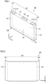
- Fig. 1 is a perspective view showing a configuration of a battery cell 100.
- Battery cell 100 is a lithium ion battery, for example.
- battery cell 100 includes electrode terminals 110, a housing 120 (exterior container), a gas-discharge valve 130, and an electrolyte solution injection portion 140.
- Electrode terminals 110 are formed on housing 120. Electrode terminals 110 have a positive electrode terminal 111 and a negative electrode terminal 112 as two electrode terminals 110 arranged side by side along a first direction (X direction). Positive electrode terminal 111 and negative electrode terminal 112 are provided to be separated from each other in the X direction.
- Housing 120 has a rectangular parallelepiped shape (prismatic shape), and forms the external appearance of battery cell 100.
- An electrode assembly (not shown) and an electrolyte solution (not shown) are accommodated in housing 120.
- Housing 120 is an exterior container having an upper surface 121, a lower surface 122, long side surfaces 123, 124, and short side surfaces 125, 126.
- the long side surfaces 123, 124 face each other along a second direction (Y direction) orthogonal to the first direction (X direction).
- Electrode terminals 110 are disposed on upper surface 121.
- Lower surface 122 faces upper surface 121 along the third direction (Z direction) orthogonal to the first direction (X direction) and the second direction (Y direction).
- Z direction third direction orthogonal to the first direction (X direction) and the second direction (Y direction).
- Each of upper surface 121 and lower surface 122 is a flat surface orthogonal to the Z direction.
- Each of long side surfaces 123, 124 is constituted of a flat surface orthogonal to the Y direction. Each of long side surfaces 123, 124 has the largest area among those of the plurality of side surfaces of housing 120. Each of long side surfaces 123, 124 has a rectangular shape when viewed in the Y direction. Each of long side surfaces 123, 124 has a rectangular shape in which the X direction corresponds to the long-side direction and the Z direction corresponds to the short-side direction when viewed in the Y direction.
- a plurality of battery cells 100 are stacked such that long side surfaces 123 of battery cells 100 adjacent to each other in the Y direction face each other and long side surfaces 124 of battery cells 100 adjacent to each other in the Y direction face each other.
- positive electrode terminals 111 and negative electrode terminals 112 are alternately arranged in the Y direction in which the plurality of battery cells 100 are stacked.
- Gas-discharge valve 130 is provided in upper surface 121. When internal pressure of housing 120 becomes more than or equal to a predetermined value due to gas generated inside housing 120, gas-discharge valve 130 discharges the gas to the outside of housing 120.
- Electrolyte solution injection portion 140 is provided on upper surface 121. Electrolyte solution injection portion 140 is provided with an injection hole that extends through upper surface 121 and that communicates with the inside of housing 120, and includes a rivet that closes the injection hole. After the electrolyte solution is injected into housing 120 through the injection hole, the injection hole is closed by the rivet.
- Shoulder portions 150 are regions located at upper surface 121 of housing 120 on the outer sides with respect to electrode terminal 110 in the X direction. Shoulder portions 150 include a shoulder portion 151 on the positive electrode terminal 111 side and a shoulder portion 152 on the negative electrode terminal 112 side.
- Fig. 2 is a plan view showing a film 200 (insulating sheet) provided on the outer surface of housing 120.
- film 200 includes a main body portion 210 and protrusions 220 protruding from main body portion 210 in the Z direction.
- Protrusions 220 include protrusions 221, 222 positioned at both ends in the X direction.
- Battery cell 100 is accommodated in main body portion 210 that has a shape of pouch.
- Each of protrusions 220 is folded toward upper surface 121 of housing 120.
- Film 200 is a shrink film shrunk by heat.
- Film 200 can be composed of a PET (polyethylene terephthalate) material having a thickness of, for example, about 0.07 mm.
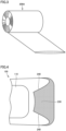
- Fig. 3 is a diagram showing a roll 200A of a pouch-shaped sheet material for forming film 200.
- Pouch-shaped film 200 can be formed by cutting, per predetermined length, roll 200A that is continuous in the Z direction.
- Fig. 4 is a top view showing shoulder portion 150
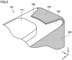
- Fig. 5 is a perspective view of shoulder portion 150.
- film 200 provided on the outer surface of housing 120 is formed to cover long side surfaces 123, 124 and short side surfaces 125, 126 of housing 120.
- Each of protrusions 220 (folded portions) of film 200 includes a peak portion 230 and valley portions 240, peak portion 230 protruding from the short side surface 125, 126 side to the electrode terminal 110 side along the first direction (X direction), valley portions 240 being located on both sides with respect to peak portion 230 in the second direction (Y direction) orthogonal to the X direction, each of the valley portions 240 being recessed toward a side away from electrode terminal 110.
- valley portions 240 At each of valley portions 240, upper surface 121 is not covered by film 200 and is exposed.
- the contour of the top portion of peak portion 230 has a substantially flat portion along the second direction (Y direction).
- the expression "substantially flat” does not mean a complete flatness, and also encompasses a case where a slight curvature is included. It should be noted that the top portion of peak portion 230 may be acute.
- the top portion of peak portion 230 is located at a position separated from electrode terminals 110 along the first direction (X direction).
- film 200 When film 200 is thermally shrunk, film 200 may be deformed into an unintended shape. For example, when no valley portion 240 (exposed portion) is formed and film 200 is shrunk with film 200 being laid over itself on upper surface 121 of housing 120, it is concerned that deformed film 200 protrudes in the Z direction and interferes with other components (components located therearound) included in the battery module, such as a separator member provided between adjacent battery cells 100.
- a box-shaped film instead of pouch-shaped film 200 shown in Fig. 2 .
- control can be performed more precisely than the control of an amount of insertion of battery cell 100 into main body portion 210 of pouch-shaped film 200.
- film 200 of the present embodiment since main body portion 210 and protrusions 220 are formed to form valley portions 240 (exposed portions) on both sides with respect to peak portion 230, film 200 is suppressed from being shrunk with film 200 being laid over itself on upper surface 121 of housing 120 of battery cell 100. As a result, film 200 is suppressed from protruding too much unintendedly, thereby suppressing interference with a member located therearound. As a result, a function of the separator between battery cells 100 can be suppressed from being decreased and welding between electrode terminal 110 and a bus bar that electrically connects the plurality of battery cells 100 together can be suppressed from being failed due to a variation in height among the plurality of battery cells 100.
Landscapes
- Chemical & Material Sciences (AREA)
- Chemical Kinetics & Catalysis (AREA)
- Electrochemistry (AREA)
- General Chemical & Material Sciences (AREA)
- Sealing Battery Cases Or Jackets (AREA)
- Electric Double-Layer Capacitors Or The Like (AREA)
- Connection Of Batteries Or Terminals (AREA)
- Filling, Topping-Up Batteries (AREA)
- Battery Mounting, Suspending (AREA)
Abstract
A battery cell (100) includes: an electrode assembly; an exterior container (120); two electrode terminals (111, 112) provided on an upper surface (121) of the exterior container (120) and arranged side by side in a first direction; and an insulating sheet (200) that is in a form of a film and that is provided on the outer surface of the exterior container (120). The insulating sheet (200) has a folded portion (220) that reaches the upper surface (121) from a short side surface (125, 126) of the exterior container (120). The folded portion (220) includes a peak portion (230) and valley portions (240), the peak portion (230) protruding from the short side surface (125, 126) side to the two electrode terminals (111, 112) side along the first direction, the valley portions (240) being located on both sides with respect to the peak portion (230) in a second direction orthogonal to the first direction, each of the valley portions (240) being recessed toward a side away from the two electrode terminals (111, 112).
Description
- This nonprovisional application is based on
Japanese Patent Application No. 2021-194227 filed on November 30, 2021 - The present technology relates to a battery cell.
- There has been conventionally known a battery cell including an insulating film that covers an outer surface of an exterior container having a prismatic shape. Such an insulating film and a battery cell including the insulating film are described, for example, in
Japanese Patent Laying-Open No. 2014-63686 Japanese Patent Laying-Open No. 2016-154147 - In a step of bringing the insulating film into close contact with the exterior container, the insulating film may be deformed into an unintended shape. For example, when the deformed insulating film protrudes on the upper surface of the exterior container or the like, it is concerned that the deformed insulating film interferes with other components included in the battery module.
- An object of the present technology is to provide a battery cell in which an insulating sheet that covers an exterior container is suppressed from interfering with a member located therearound.
- A battery cell according to the present technology includes: an electrode assembly; an exterior container that accommodates the electrode assembly and that has a prismatic shape with an outer surface including an upper surface, a long side surface, and a short side surface; two electrode terminals provided on the upper surface of the exterior container and arranged side by side in a first direction; and an insulating sheet that is in a form of a film and that is provided on the outer surface of the exterior container. The insulating sheet has a folded portion that reaches the upper surface from the short side surface of the exterior container. The folded portion includes a peak portion and valley portions, the peak portion protruding from the short side surface side to the two electrode terminals side along the first direction, the valley portions being located on both sides with respect to the peak portion in a second direction orthogonal to the first direction, each of the valley portions being recessed toward a side away from the two electrode terminals.
- The foregoing and other objects, features, aspects and advantages of the present invention will become more apparent from the following detailed description of the present invention when taken in conjunction with the accompanying drawings.
-
-
Fig. 1 is a perspective view showing a configuration of a battery cell. -
Fig. 2 is a plan view showing an insulating sheet provided on an outer surface of an exterior container. -
Fig. 3 is a diagram showing a roll of a pouch-shaped sheet material for forming the insulating sheet. -
Fig. 4 is a top view showing a shoulder portion of the exterior container. -
Fig. 5 is a perspective view showing the shoulder portion of the exterior container. - Hereinafter, embodiments of the present technology will be described. It should be noted that the same or corresponding portions are denoted by the same reference characters, and may not be described repeatedly.
- It should be noted that in the embodiments described below, when reference is made to number, amount, and the like, the scope of the present technology is not necessarily limited to the number, amount, and the like unless otherwise stated particularly. Further, in the embodiments described below, each component is not necessarily essential to the present technology unless otherwise stated particularly. Further, the present technology is not limited to one that necessarily exhibits all the functions and effects stated in the present embodiment.
- It should be noted that in the present specification, the terms "comprise", "include", and "have" are open-end terms. That is, when a certain configuration is included, a configuration other than the foregoing configuration may or may not be included.
- Also, in the present specification, when geometric terms and terms representing positional/directional relations are used, for example, when terms such as "parallel", "orthogonal", "obliquely at 45°", "coaxial", and "along" are used, these terms permit manufacturing errors or slight fluctuations. In the present specification, when terms representing relative positional relations such as "upper side" and "lower side" are used, each of these terms is used to indicate a relative positional relation in one state, and the relative positional relation may be reversed or turned at any angle in accordance with an installation direction of each mechanism (for example, the entire mechanism is reversed upside down).
- In the present specification, the term "battery" is not limited to a lithium ion battery, and may include another battery such as a nickel-metal hydride battery. In the present specification, the term "electrode" may collectively represent a positive electrode and a negative electrode. Further, the term "electrode plate" may collectively represent a positive electrode plate and a negative electrode plate.
- In the present specification, when the terms "power storage cell" or "power storage module" are used, the "power storage cell" or the "power storage module" is not limited to a battery cell or a battery module, and may include a capacitor cell or a capacitor module.
-
Fig. 1 is a perspective view showing a configuration of abattery cell 100.Battery cell 100 is a lithium ion battery, for example. - As shown in
Fig. 1 ,battery cell 100 includeselectrode terminals 110, a housing 120 (exterior container), a gas-discharge valve 130, and an electrolytesolution injection portion 140. -
Electrode terminals 110 are formed onhousing 120.Electrode terminals 110 have apositive electrode terminal 111 and anegative electrode terminal 112 as twoelectrode terminals 110 arranged side by side along a first direction (X direction).Positive electrode terminal 111 andnegative electrode terminal 112 are provided to be separated from each other in the X direction. -
Housing 120 has a rectangular parallelepiped shape (prismatic shape), and forms the external appearance ofbattery cell 100. An electrode assembly (not shown) and an electrolyte solution (not shown) are accommodated inhousing 120.Housing 120 is an exterior container having anupper surface 121, alower surface 122,long side surfaces short side surfaces long side surfaces -
Electrode terminals 110 are disposed onupper surface 121.Lower surface 122 facesupper surface 121 along the third direction (Z direction) orthogonal to the first direction (X direction) and the second direction (Y direction). Each ofupper surface 121 andlower surface 122 is a flat surface orthogonal to the Z direction. - Each of
long side surfaces long side surfaces housing 120. Each oflong side surfaces long side surfaces - A plurality of
battery cells 100 are stacked such thatlong side surfaces 123 ofbattery cells 100 adjacent to each other in the Y direction face each other andlong side surfaces 124 ofbattery cells 100 adjacent to each other in the Y direction face each other. Thus,positive electrode terminals 111 andnegative electrode terminals 112 are alternately arranged in the Y direction in which the plurality ofbattery cells 100 are stacked. - Gas-
discharge valve 130 is provided inupper surface 121. When internal pressure ofhousing 120 becomes more than or equal to a predetermined value due to gas generated insidehousing 120, gas-discharge valve 130 discharges the gas to the outside ofhousing 120. - Electrolyte
solution injection portion 140 is provided onupper surface 121. Electrolytesolution injection portion 140 is provided with an injection hole that extends throughupper surface 121 and that communicates with the inside ofhousing 120, and includes a rivet that closes the injection hole. After the electrolyte solution is injected intohousing 120 through the injection hole, the injection hole is closed by the rivet. -
Shoulder portions 150 are regions located atupper surface 121 ofhousing 120 on the outer sides with respect toelectrode terminal 110 in the X direction.Shoulder portions 150 include ashoulder portion 151 on thepositive electrode terminal 111 side and ashoulder portion 152 on thenegative electrode terminal 112 side. -
Fig. 2 is a plan view showing a film 200 (insulating sheet) provided on the outer surface ofhousing 120. As shown inFig. 2 ,film 200 includes amain body portion 210 andprotrusions 220 protruding frommain body portion 210 in the Z direction.Protrusions 220 includeprotrusions Battery cell 100 is accommodated inmain body portion 210 that has a shape of pouch. Each ofprotrusions 220 is folded towardupper surface 121 ofhousing 120. -
Film 200 is a shrink film shrunk by heat.Film 200 can be composed of a PET (polyethylene terephthalate) material having a thickness of, for example, about 0.07 mm. - After
battery cell 100 is accommodated in pouch-shapedfilm 200, an excess portion offilm 200 is thermally shrunk by causing it to pass through a shrink furnace. Thus,film 200 is brought into close contact with the outer surface ofbattery cell 100. -
Fig. 3 is a diagram showing aroll 200A of a pouch-shaped sheet material for formingfilm 200. Pouch-shapedfilm 200 can be formed by cutting, per predetermined length,roll 200A that is continuous in the Z direction. -
Fig. 4 is a top view showingshoulder portion 150, andFig. 5 is a perspective view ofshoulder portion 150. As shown inFigs. 4 and5 ,film 200 provided on the outer surface ofhousing 120 is formed to cover long side surfaces 123, 124 and short side surfaces 125, 126 ofhousing 120. Each of protrusions 220 (folded portions) offilm 200 includes apeak portion 230 andvalley portions 240,peak portion 230 protruding from theshort side surface electrode terminal 110 side along the first direction (X direction),valley portions 240 being located on both sides with respect topeak portion 230 in the second direction (Y direction) orthogonal to the X direction, each of thevalley portions 240 being recessed toward a side away fromelectrode terminal 110. At each ofvalley portions 240,upper surface 121 is not covered byfilm 200 and is exposed. - In the example of
Figs. 4 and5 , the contour of the top portion ofpeak portion 230 has a substantially flat portion along the second direction (Y direction). The expression "substantially flat" does not mean a complete flatness, and also encompasses a case where a slight curvature is included. It should be noted that the top portion ofpeak portion 230 may be acute. The top portion ofpeak portion 230 is located at a position separated fromelectrode terminals 110 along the first direction (X direction). - When
film 200 is thermally shrunk,film 200 may be deformed into an unintended shape. For example, when no valley portion 240 (exposed portion) is formed andfilm 200 is shrunk withfilm 200 being laid over itself onupper surface 121 ofhousing 120, it is concerned thatdeformed film 200 protrudes in the Z direction and interferes with other components (components located therearound) included in the battery module, such as a separator member provided betweenadjacent battery cells 100. - In order to precisely control the size after the thermal shrinkage, it is considered to form a box-shaped film instead of pouch-shaped
film 200 shown inFig. 2 . By forming the box-shaped film, control can be performed more precisely than the control of an amount of insertion ofbattery cell 100 intomain body portion 210 of pouch-shapedfilm 200. However, it is concerned that the use of such a box-shaped film results in complicated manufacturing process or increased manufacturing cost. - On the other hand, according to
film 200 of the present embodiment, sincemain body portion 210 andprotrusions 220 are formed to form valley portions 240 (exposed portions) on both sides with respect topeak portion 230,film 200 is suppressed from being shrunk withfilm 200 being laid over itself onupper surface 121 ofhousing 120 ofbattery cell 100. As a result,film 200 is suppressed from protruding too much unintendedly, thereby suppressing interference with a member located therearound. As a result, a function of the separator betweenbattery cells 100 can be suppressed from being decreased and welding betweenelectrode terminal 110 and a bus bar that electrically connects the plurality ofbattery cells 100 together can be suppressed from being failed due to a variation in height among the plurality ofbattery cells 100. - Although the embodiments of the present invention have been described and illustrated in detail, it is clearly understood that the same is by way of illustration and example only and is not to be taken by way of limitation, the scope of the present invention being interpreted by the terms of the appended claims. The scope of the present invention is defined by the terms of the claims, and is intended to include any modifications within the scope and meaning equivalent to the terms of the claims.
Claims (5)
- A battery cell comprising:an electrode assembly;an exterior container (120) that accommodates the electrode assembly and that has a prismatic shape with an outer surface including an upper surface (121), a long side surface (123, 124), and a short side surface (125, 126);two electrode terminals (111, 112) provided on the upper surface (121) of the exterior container (120) and arranged side by side in a first direction; andan insulating sheet (200) that is in a form of a film and that is provided on the outer surface of the exterior container (120), whereinthe insulating sheet (200) has a folded portion (220) that reaches the upper surface (121) from the short side surface (125, 126) of the exterior container (120), andthe folded portion (220) includes a peak portion (230) and valley portions (240), the peak portion (230) protruding from the short side surface (125, 126) side to the two electrode terminals (111, 112) side along the first direction, the valley portions (240) being located on both sides with respect to the peak portion (230) in a second direction orthogonal to the first direction, each of the valley portions (240) being recessed toward a side away from the two electrode terminals (111, 112).
- The battery cell according to claim 1, wherein the insulating sheet (200) is a shrink film shrunk by heat.
- The battery cell according to claim 1 or 2, wherein the insulating sheet (200) at least covers the long side surface (123, 124) and the short side surface (125, 126) of the exterior container (120).
- The battery cell according to any one of claims 1 to 3, wherein a contour of a top portion of the peak portion (230) has a substantially flat portion along the second direction.
- The battery cell according to claim 4, wherein the top portion is located at a position separated from the two electrode terminals (111, 112) along the first direction.
Applications Claiming Priority (1)
| Application Number | Priority Date | Filing Date | Title |
|---|---|---|---|
| JP2021194227A JP7470091B2 (en) | 2021-11-30 | 2021-11-30 | Battery Cell |
Publications (1)
| Publication Number | Publication Date |
|---|---|
| EP4187685A1 true EP4187685A1 (en) | 2023-05-31 |
Family
ID=84359145
Family Applications (1)
| Application Number | Title | Priority Date | Filing Date |
|---|---|---|---|
| EP22207841.2A Pending EP4187685A1 (en) | 2021-11-30 | 2022-11-16 | Battery cell |
Country Status (5)
| Country | Link |
|---|---|
| US (1) | US12586878B2 (en) |
| EP (1) | EP4187685A1 (en) |
| JP (2) | JP7470091B2 (en) |
| KR (1) | KR102835811B1 (en) |
| CN (1) | CN116207458A (en) |
Families Citing this family (1)
| Publication number | Priority date | Publication date | Assignee | Title |
|---|---|---|---|---|
| KR20250128704A (en) * | 2024-02-21 | 2025-08-28 | 삼성에스디아이 주식회사 | Secondary battery with exterior insulating tape and manufacturing method thereof |
Citations (5)
| Publication number | Priority date | Publication date | Assignee | Title |
|---|---|---|---|---|
| US20110195301A1 (en) * | 2010-02-05 | 2011-08-11 | Sanyo Electric Co., Ltd. | Prismatic cell, method of manufacturing thereof, and assembled battery using the same |
| JP2014063686A (en) | 2012-09-24 | 2014-04-10 | Gs Yuasa Corp | Battery |
| JP2016154147A (en) | 2016-03-31 | 2016-08-25 | 株式会社Gsユアサ | Battery |
| JP2018028964A (en) * | 2014-12-26 | 2018-02-22 | 日立オートモティブシステムズ株式会社 | Prismatic secondary battery |
| JP2021194227A (en) | 2020-06-12 | 2021-12-27 | 竹内工業株式会社 | Stick-shaped cosmetic storage container |
Family Cites Families (10)
| Publication number | Priority date | Publication date | Assignee | Title |
|---|---|---|---|---|
| JPH0628987U (en) * | 1992-09-10 | 1994-04-15 | 日本電池株式会社 | Sealed storage battery |
| WO2012067045A1 (en) | 2010-11-18 | 2012-05-24 | 三洋電機株式会社 | Battery assembly, separator for battery assembly, and vehicle provided with same |
| JP5743791B2 (en) | 2011-08-02 | 2015-07-01 | 三洋電機株式会社 | Power supply device and vehicle equipped with power supply device |
| JP6179285B2 (en) | 2012-10-12 | 2017-08-16 | 株式会社Gsユアサ | Storage element, covering sheet, and container covering method |
| JP2015228359A (en) | 2014-05-02 | 2015-12-17 | 住友電気工業株式会社 | Rectangular parallelepiped power storage device, and manufacturing method thereof |
| US20170250388A1 (en) | 2014-09-03 | 2017-08-31 | Hitachi Automotive Systems, Ltd. | Prismatic secondary battery |
| JP2016139532A (en) * | 2015-01-28 | 2016-08-04 | 日立オートモティブシステムズ株式会社 | Rectangular secondary battery |
| CN111052433A (en) * | 2017-10-24 | 2020-04-21 | 松下知识产权经营株式会社 | Battery cells and battery packs using the same |
| JP7031300B2 (en) * | 2017-12-27 | 2022-03-08 | 株式会社Gsユアサ | Power storage element and power storage device |
| EP3920295B1 (en) | 2019-01-29 | 2026-01-07 | Panasonic Holdings Corporation | Stacked secondary battery |
-
2021
- 2021-11-30 JP JP2021194227A patent/JP7470091B2/en active Active
-
2022
- 2022-11-16 EP EP22207841.2A patent/EP4187685A1/en active Pending
- 2022-11-16 US US18/056,021 patent/US12586878B2/en active Active
- 2022-11-22 KR KR1020220156946A patent/KR102835811B1/en active Active
- 2022-11-29 CN CN202211508992.XA patent/CN116207458A/en active Pending
-
2024
- 2024-04-04 JP JP2024060826A patent/JP7725649B2/en active Active
Patent Citations (5)
| Publication number | Priority date | Publication date | Assignee | Title |
|---|---|---|---|---|
| US20110195301A1 (en) * | 2010-02-05 | 2011-08-11 | Sanyo Electric Co., Ltd. | Prismatic cell, method of manufacturing thereof, and assembled battery using the same |
| JP2014063686A (en) | 2012-09-24 | 2014-04-10 | Gs Yuasa Corp | Battery |
| JP2018028964A (en) * | 2014-12-26 | 2018-02-22 | 日立オートモティブシステムズ株式会社 | Prismatic secondary battery |
| JP2016154147A (en) | 2016-03-31 | 2016-08-25 | 株式会社Gsユアサ | Battery |
| JP2021194227A (en) | 2020-06-12 | 2021-12-27 | 竹内工業株式会社 | Stick-shaped cosmetic storage container |
Also Published As
| Publication number | Publication date |
|---|---|
| JP7470091B2 (en) | 2024-04-17 |
| US20230170591A1 (en) | 2023-06-01 |
| JP7725649B2 (en) | 2025-08-19 |
| KR102835811B1 (en) | 2025-07-21 |
| US12586878B2 (en) | 2026-03-24 |
| CN116207458A (en) | 2023-06-02 |
| JP2024094343A (en) | 2024-07-09 |
| KR20230081642A (en) | 2023-06-07 |
| JP2023080728A (en) | 2023-06-09 |
Similar Documents
| Publication | Publication Date | Title |
|---|---|---|
| KR100553753B1 (en) | Pouch Type Secondary Battery | |
| EP2348557B1 (en) | Secondary battery | |
| US12525667B2 (en) | Battery module | |
| EP4187685A1 (en) | Battery cell | |
| CN117280540A (en) | Secondary battery with improved terminal structure | |
| EP4333157A1 (en) | Battery module | |
| US20240170794A1 (en) | Battery Module | |
| JP7705379B2 (en) | Battery Module | |
| US20240079710A1 (en) | Battery module | |
| JP7696939B2 (en) | Battery pack and manufacturing method thereof | |
| US20240234996A9 (en) | Battery module | |
| US20240234890A9 (en) | Battery module | |
| US20250233258A1 (en) | Separator and battery assembly | |
| EP4723356A1 (en) | Busbar holder and battery module including same | |
| US20240088456A1 (en) | Battery module | |
| JP7804728B2 (en) | Battery cell, battery, power receiving device, and method of manufacturing battery cell | |
| EP4333156A1 (en) | Battery module | |
| US20260066479A1 (en) | Battery assembly and battery pack | |
| US20260058253A1 (en) | Battery assembly | |
| US20250105412A1 (en) | Secondary battery and battery assembly | |
| US20240429519A1 (en) | Battery pack | |
| US20250015447A1 (en) | Battery pack | |
| US20240234914A9 (en) | Battery module | |
| US20240291096A1 (en) | Battery pack | |
| KR20250015704A (en) | Battery pack |
Legal Events
| Date | Code | Title | Description |
|---|---|---|---|
| PUAI | Public reference made under article 153(3) epc to a published international application that has entered the european phase |
Free format text: ORIGINAL CODE: 0009012 |
|
| STAA | Information on the status of an ep patent application or granted ep patent |
Free format text: STATUS: REQUEST FOR EXAMINATION WAS MADE |
|
| 17P | Request for examination filed |
Effective date: 20221116 |
|
| AK | Designated contracting states |
Kind code of ref document: A1 Designated state(s): AL AT BE BG CH CY CZ DE DK EE ES FI FR GB GR HR HU IE IS IT LI LT LU LV MC ME MK MT NL NO PL PT RO RS SE SI SK SM TR |