EP4187636A1 - Electrode drying device - Google Patents
Electrode drying device Download PDFInfo
- Publication number
- EP4187636A1 EP4187636A1 EP22767308.4A EP22767308A EP4187636A1 EP 4187636 A1 EP4187636 A1 EP 4187636A1 EP 22767308 A EP22767308 A EP 22767308A EP 4187636 A1 EP4187636 A1 EP 4187636A1
- Authority
- EP
- European Patent Office
- Prior art keywords
- electrode
- interrupting member
- electrode sheet
- region
- inflow port
- Prior art date
- Legal status (The legal status is an assumption and is not a legal conclusion. Google has not performed a legal analysis and makes no representation as to the accuracy of the status listed.)
- Granted
Links
Images


Classifications
-
- F—MECHANICAL ENGINEERING; LIGHTING; HEATING; WEAPONS; BLASTING
- F26—DRYING
- F26B—DRYING SOLID MATERIALS OR OBJECTS BY REMOVING LIQUID THEREFROM
- F26B13/00—Machines and apparatus for drying fabrics, fibres, yarns, or other materials in long lengths, with progressive movement
- F26B13/001—Drying and oxidising yarns, ribbons or the like
- F26B13/002—Drying coated, e.g. enamelled, varnished, wires
-
- F—MECHANICAL ENGINEERING; LIGHTING; HEATING; WEAPONS; BLASTING
- F26—DRYING
- F26B—DRYING SOLID MATERIALS OR OBJECTS BY REMOVING LIQUID THEREFROM
- F26B13/00—Machines and apparatus for drying fabrics, fibres, yarns, or other materials in long lengths, with progressive movement
- F26B13/008—Controlling the moisture profile across the width of the material
-
- F—MECHANICAL ENGINEERING; LIGHTING; HEATING; WEAPONS; BLASTING
- F26—DRYING
- F26B—DRYING SOLID MATERIALS OR OBJECTS BY REMOVING LIQUID THEREFROM
- F26B13/00—Machines and apparatus for drying fabrics, fibres, yarns, or other materials in long lengths, with progressive movement
- F26B13/10—Arrangements for feeding, heating or supporting materials; Controlling movement, tension or position of materials
- F26B13/12—Controlling movement, tension or position of material
-
- F—MECHANICAL ENGINEERING; LIGHTING; HEATING; WEAPONS; BLASTING
- F26—DRYING
- F26B—DRYING SOLID MATERIALS OR OBJECTS BY REMOVING LIQUID THEREFROM
- F26B25/00—Details of general application not covered by group F26B21/00 or F26B23/00
- F26B25/008—Seals, locks, e.g. gas barriers or air curtains, for drying enclosures
-
- F—MECHANICAL ENGINEERING; LIGHTING; HEATING; WEAPONS; BLASTING
- F26—DRYING
- F26B—DRYING SOLID MATERIALS OR OBJECTS BY REMOVING LIQUID THEREFROM
- F26B25/00—Details of general application not covered by group F26B21/00 or F26B23/00
- F26B25/06—Chambers, containers, or receptacles
- F26B25/08—Parts thereof
- F26B25/12—Walls or sides; Doors
-
- H—ELECTRICITY
- H01—ELECTRIC ELEMENTS
- H01M—PROCESSES OR MEANS, e.g. BATTERIES, FOR THE DIRECT CONVERSION OF CHEMICAL ENERGY INTO ELECTRICAL ENERGY
- H01M4/00—Electrodes
- H01M4/02—Electrodes composed of, or comprising, active material
- H01M4/04—Processes of manufacture in general
-
- H—ELECTRICITY
- H01—ELECTRIC ELEMENTS
- H01M—PROCESSES OR MEANS, e.g. BATTERIES, FOR THE DIRECT CONVERSION OF CHEMICAL ENERGY INTO ELECTRICAL ENERGY
- H01M4/00—Electrodes
- H01M4/02—Electrodes composed of, or comprising, active material
- H01M4/04—Processes of manufacture in general
- H01M4/0402—Methods of deposition of the material
- H01M4/0404—Methods of deposition of the material by coating on electrode collectors
-
- H—ELECTRICITY
- H01—ELECTRIC ELEMENTS
- H01M—PROCESSES OR MEANS, e.g. BATTERIES, FOR THE DIRECT CONVERSION OF CHEMICAL ENERGY INTO ELECTRICAL ENERGY
- H01M4/00—Electrodes
- H01M4/02—Electrodes composed of, or comprising, active material
- H01M4/04—Processes of manufacture in general
- H01M4/0471—Processes of manufacture in general involving thermal treatment, e.g. firing, sintering, backing particulate active material, thermal decomposition, pyrolysis
-
- H—ELECTRICITY
- H01—ELECTRIC ELEMENTS
- H01M—PROCESSES OR MEANS, e.g. BATTERIES, FOR THE DIRECT CONVERSION OF CHEMICAL ENERGY INTO ELECTRICAL ENERGY
- H01M4/00—Electrodes
- H01M4/02—Electrodes composed of, or comprising, active material
- H01M4/13—Electrodes for accumulators with non-aqueous electrolyte, e.g. for lithium-accumulators; Processes of manufacture thereof
- H01M4/139—Processes of manufacture
-
- F—MECHANICAL ENGINEERING; LIGHTING; HEATING; WEAPONS; BLASTING
- F26—DRYING
- F26B—DRYING SOLID MATERIALS OR OBJECTS BY REMOVING LIQUID THEREFROM
- F26B21/00—Arrangements for supplying or controlling air or other gases for drying solid materials or objects
- F26B21/40—Arrangements for supplying or controlling air or other gases for drying solid materials or objects using gases other than air
-
- F—MECHANICAL ENGINEERING; LIGHTING; HEATING; WEAPONS; BLASTING
- F26—DRYING
- F26B—DRYING SOLID MATERIALS OR OBJECTS BY REMOVING LIQUID THEREFROM
- F26B3/00—Drying solid materials or objects by processes involving the application of heat
- F26B3/02—Drying solid materials or objects by processes involving the application of heat by convection, i.e. heat being conveyed from a heat source to the materials or objects to be dried by a gas or vapour, e.g. air
- F26B3/04—Drying solid materials or objects by processes involving the application of heat by convection, i.e. heat being conveyed from a heat source to the materials or objects to be dried by a gas or vapour, e.g. air the gas or vapour circulating over or surrounding the materials or objects to be dried
-
- F—MECHANICAL ENGINEERING; LIGHTING; HEATING; WEAPONS; BLASTING
- F26—DRYING
- F26B—DRYING SOLID MATERIALS OR OBJECTS BY REMOVING LIQUID THEREFROM
- F26B3/00—Drying solid materials or objects by processes involving the application of heat
- F26B3/28—Drying solid materials or objects by processes involving the application of heat by radiation, e.g. from the sun
- F26B3/30—Drying solid materials or objects by processes involving the application of heat by radiation, e.g. from the sun from infrared-emitting elements
-
- Y—GENERAL TAGGING OF NEW TECHNOLOGICAL DEVELOPMENTS; GENERAL TAGGING OF CROSS-SECTIONAL TECHNOLOGIES SPANNING OVER SEVERAL SECTIONS OF THE IPC; TECHNICAL SUBJECTS COVERED BY FORMER USPC CROSS-REFERENCE ART COLLECTIONS [XRACs] AND DIGESTS
- Y02—TECHNOLOGIES OR APPLICATIONS FOR MITIGATION OR ADAPTATION AGAINST CLIMATE CHANGE
- Y02E—REDUCTION OF GREENHOUSE GAS [GHG] EMISSIONS, RELATED TO ENERGY GENERATION, TRANSMISSION OR DISTRIBUTION
- Y02E60/00—Enabling technologies; Technologies with a potential or indirect contribution to GHG emissions mitigation
- Y02E60/10—Energy storage using batteries
-
- Y—GENERAL TAGGING OF NEW TECHNOLOGICAL DEVELOPMENTS; GENERAL TAGGING OF CROSS-SECTIONAL TECHNOLOGIES SPANNING OVER SEVERAL SECTIONS OF THE IPC; TECHNICAL SUBJECTS COVERED BY FORMER USPC CROSS-REFERENCE ART COLLECTIONS [XRACs] AND DIGESTS
- Y02—TECHNOLOGIES OR APPLICATIONS FOR MITIGATION OR ADAPTATION AGAINST CLIMATE CHANGE
- Y02P—CLIMATE CHANGE MITIGATION TECHNOLOGIES IN THE PRODUCTION OR PROCESSING OF GOODS
- Y02P70/00—Climate change mitigation technologies in the production process for final industrial or consumer products
- Y02P70/50—Manufacturing or production processes characterised by the final manufactured product
Definitions
- the present disclosure relates to an electrode drying device, and more particularly, to an electrode drying device that removes moisture from an electrode sheet in a battery manufacturing process.
- a secondary battery has attracted considerable attention as an energy source for power-driven devices, such as an electric bicycle, an electric vehicle, and a hybrid electric vehicle, as well as an energy source for mobile devices, such as a mobile phone, a digital camera, a laptop computer and a wearable device.
- the secondary battery may be classified based on the shape of a battery case into a cylindrical battery having an electrode assembly mounted in a cylindrical metal can, a prismatic battery having an electrode assembly mounted in a prismatic metal can, and a pouch type battery having an electrode assembly mounted in a pouch-shaped case made of a laminated aluminum sheet.
- the secondary battery may be classified based on the structure of an electrode assembly having a structure in which a positive electrode and a negative electrode are stacked with a separator being interposed between the positive electrode and the negative electrode.
- a jelly-roll (wound) type structure in which a long sheet type positive electrode and a long sheet type negative electrode are wound with a separator being interposed between the positive electrode and the negative electrode
- a stacked (laminated) type structure in which pluralities of positive electrodes and negative electrodes, cut into predetermined unit sizes, are sequentially stacked with separators being interposed between the positive electrodes and the negative electrodes, or the like.
- a stacked/folded type electrode assembly which is a combination of the jelly-roll type electrode assembly and the stacked type electrode assembly.
- the electrode for a secondary battery there are a method of dispersing an active material, a conductive material and/or a binder, etc. in a solvent to prepare a slurry, and then applying the slurry directly to a current collector to form the electrode, or a method of applying the slurry onto a separate support and laminating a film peeled from the support on a current collector to form the electrode.
- the electrode sheet formed by the above-mentioned method undergoes a drying process for removing residual solvent (NMP) or residual moisture, wherein the dry condition of the electrode sheet can greatly affect the quality of the battery.
- the moisture remaining in the electrode sheet may reduce an oxidation-reduction reaction between the positive electrode and the negative electrode, whereby the rated energy of the battery may not be generated, or the charge/discharge cycle characteristics of the battery may be deteriorated.
- the remaining moisture can react with the electrolyte to produce hydrogen fluoride, and the produced hydrogen fluoride may cause a decrease in ionic conductivity of the secondary battery, and a safety problem such as electrode corrosion.
- a vacuum heating and drying method is mainly used in which the chamber is converted to a vacuum state and a heater or hot air system disposed in the chamber heats the airflow in the chamber, but in recent years, electrode high-speed running drying (Roll to Roll Drying, R2R Drying, hereinafter referred to as 'roll-to-roll') process is mainly used.
- electrode high-speed running drying Roll to Roll Drying, R2R Drying, hereinafter referred to as 'roll-to-roll'
- the roll-to-roll process has an advantage in that a continuous process is possible by directly heating the electrode surface while running the electrode roll, but has a disadvantage in that nonuniform pressure gradient or temperature gradient may be generated in the chamber due to the inflow of air outside the chamber through an inlet port for inputting the electrode. If the pressure or temperature gradient inside the chamber is not uniform, a part of the electrode sheet is excessively dried, and a deviation in the dry condition may occur, which may cause the increase in the defect rate of the final product.
- an electrode drying device comprising: a transfer unit that transfers an electrode sheet having an electrode slurry coated onto the current collector, and a drying chamber including an inflow port where the electrode sheet transferred by the transfer unit enters, wherein an interrupting member for adjusting the flow amount or flow velocity of outside air flowing in a drying chamber is formed at the inflow port, and a height of a central part of the interrupting member is different from a height of a peripheral part of the interrupting member.
- the height of the central part is larger than the height of the peripheral part, and the central part may be a part different from the peripheral part including both ends in the width direction of the interrupting member.
- the drying chamber includes at least one heating element, and the interrupting member may be disposed at one end of the inflow port close to the heating member.
- At least one heating element is disposed at an upper part of the drying chamber, and when the electrode sheet is transferred to the lower part of the drying chamber by the transfer unit, the interrupting member may be disposed at an upper end of the inflow port close to the upper part of the drying chamber.
- a height of the first portion of the interrupting member corresponding to the first region may be smaller than a height of a second portion of the interrupting member corresponding to the second region, and a position in the width direction of the first region in the electrode sheet may be different from a position in the width direction of the second region.
- the interrupting member includes a protrusion part, and a side end of the protrusion part is formed so as to form an acute angle with the upper end of the inflow port, and the protrusion part may refer to a portion having a larger height value in the interrupting member.
- the interrupting member includes a protrusion part, and a corner of the protrusion part has a round shape, and the protrusion part may refer to a portion having a larger height value in the interrupting member.
- the interrupting member may be integrated with the drying chamber.
- the electrode drying device of the present disclosure can dry the electrode sheet uniformly, thereby reducing the product defect rate due to the deviation in the dry condition of the electrode sheet, and improving the uniformity or reliability of the product.
- planar when referred to as “planar”, it means when a target portion is viewed from the upper side, and when referred to as “cross-sectional”, it means when a target portion is viewed from the side of a cross section cut vertically.
- Fig. 1 is a side view of an electrode drying device according to an embodiment of the present disclosure.
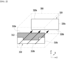
- Fig. 2 is a perspective view of a chamber according to an embodiment of the present disclosure.
- the electrode drying device 1 includes a transfer unit 200 for transferring an electrode sheet 100, and a chamber 300 through which the electrode sheet 100 transferred by the transfer unit 200 passes.
- the drying process of the electrode sheet 100 may utilize a roll-to-roll process, and in the electrode drying process utilizing the roll-to-roll process, the electrode drying process of the electrode sheet 100 can be continuously performed.
- the electrode sheet 100 may be an object of the electrode drying device 1.
- the electrode sheet 100 may be a long rectangular sheet in which an electrode slurry is coated onto a current collector.
- a current collector stainless steel, aluminum, copper, nickel, titanium, calcined carbon, and the like can be used.
- the current collector can be provided in various forms such as a film, a sheet, a foil, a net, a porous body, a foam, a nonwoven fabric structure, and the like.
- the electrode slurry herein may typically include an electrode active material, a conductive material, a binder, and a solvent, but is not limited thereto.
- the electrode sheet 100 may be either a positive electrode or a negative electrode.
- the electrode sheet 100 when the electrode sheet 100 is a positive electrode, the electrode sheet 100 can be manufactured by coating a positive electrode slurry including a positive electrode active material onto a positive electrode current collector.
- the electrode sheet 100 when the electrode sheet 100 is a negative electrode, the electrode sheet 100 can be manufactured by coating the negative electrode slurry including the negative electrode active material onto the negative electrode current collector.
- the transfer unit 200 may be for the purpose of supplying the electrode sheet 100 into the chamber 300 and out of the chamber 300.
- the transfer unit 200 may include at least one roller for guiding the moving direction of the electrode sheet 100 and/or a driving unit for driving the roller.
- the transfer unit 200 that supplies the electrode sheet 100 to the inside of the chamber 300 may be referred to as an unwinder, and the transfer unit 200 that recovers the electrode sheet 100 to the outside of the chamber 300 may be referred to as a rewinder.
- the transfer unit 200 can adjust the moving speed of the electrode sheet 100. Specifically, the transfer unit 200 can adjust the time for which the electrode sheet 100 stays in the electrode drying device 1, thereby adjusting the drying level of the electrode sheet.
- the chamber 300 may be for the purpose of providing a drying space that dries the electrode sheet 100.
- the chamber 300 may also be referred to as a drying chamber.
- the chamber 300 may include an inflow port 310 where the electrode sheet 100 enters and an outflow port 320 where the electrode sheet 100 exits.
- the chamber 300 may continuously dry the electrode sheet 100 moving from the inflow port 310 to the outflow port 320 by a roll-to-roll process, through the drying space formed between the inflow port 310 and the outflow port 320.
- the electrode sheet 100 can be moved from the inflow port 310 to the outflow port 320 by the transfer unit 200, and the transfer direction of the electrode sheet 100 is shown by arrows in Fig. 2 .
- the longitudinal direction (x-axis direction) of the electrode sheet 100 may be defined as a direction parallel to the transfer direction
- the width direction (y-axis direction) of the electrode sheet 100 may be defined as a direction perpendicular to the above-mentioned longitudinal direction.
- At least one heating member may be disposed in the inside of the chamber 300, and the airflow in the chamber 300 may be heated by the heating member, or the electrode sheet 100 entering the inner space of the chamber 300 may be heated.
- the heating member may be a hot air system including a heater, a nozzle/fan, or the like.
- the heater provided in the chamber 300 may be an IR (Infrared) heater, and may be provided in plural numbers.
- the drying efficiency and drying time of the electrode drying device 1 can be determined according to the arrangement and number of heating elements provided in the chamber 300.
- the chamber 300 may be filled with nitrogen (N 2 ) gas or an inert gas such as argon or helium while being isolated from the outside. Since the internal temperature of the chamber 300 is maintained at a high temperature, the inside can be filled with the gas as described above, thereby preventing other chemical reactions such as an oxidation reaction from occurring in the electrode sheet 100 passing through the chamber 300.
- the chamber 300 is filled with nitrogen gas that is inexpensive and is safe even if it leaks to the outside.
- the heating member such as a heater, a nozzle, or a fan disposed inside the chamber 300 may be designed so that heat can be evenly transferred to the electrode sheet 100, and specifically, it may be formed long along the width direction (y-axis direction) or may be arranged long. If a greater number of heating elements are provided in the chamber 300, it may be arranged in rows or columns along the longitudinal direction (x-axis direction).
- the magnitude of heat energy transferred to the central region and the peripheral region of the electrode sheet 100 may be different.
- the heat energy transferred to the central region of the electrode sheet 100 may be larger than that of the peripheral region.
- the heating member is a nozzle or a fan that supplies hot air
- the hot air may be transferred to the electrode sheet 100 and then move toward the edge (both ends in the y-axis direction) of the electrode sheet 100, whereby heat energy transferred to the peripheral region of the electrode sheet 100 may be larger than that of the central region.
- the central region may mean a central part in the width direction (y-axis direction), and the peripheral region may mean a peripheral part in the width direction (y-axis direction).
- the central part herein may be a part including the center in the width direction
- the peripheral part may be a part including an edge in the width direction.
- the central part may include a part located in the center when a specific part is divided equally into N
- the peripheral part may include parts located at both ends when a specific part is divided equally into N.
- the central part may be a part located in the center when a specific part is divided equally into three
- the peripheral part may be the remaining two parts excluding the part located in the center.
- the central region may be referred to as a central part
- the peripheral region may be referred to as a peripheral part.
- the expressions such as the central region or the central part, the peripheral region or the peripheral part are not used only for the electrode sheet 100, and for convenience of explanation, they can also be used for explaining the inflow port 310 or the interrupting member 312 described later.
- the internal temperature and pressure of the chamber 300 may be maintained relatively constant, but outside air flows in or inside air flows out through the opened inflow port 310 and outflow port 320, so that a temperature gradient or a pressure gradient inside the chamber 300 may change. Since the inflow of outside air or the outflow of inside air may be accompanied mainly by the movement of the electrode sheet 100, the drying environment inside the chamber 300 may change depending on the shape of the inflow port 310 or the outflow port 320, the speed at which the electrode sheet 100 is moved by the transfer unit 200, and the like.
- the flow of outside air may be concentrated in the central region of the electrode sheet 100 or may be concentrated in the peripheral region, and such a phenomenon may be accelerated according to the moving speed of the electrode sheet 100.
- the electrode sheet 100 may not be dried uniformly. As the deviation in the drying level of the electrode sheet 100 is larger, the defective rate of the battery cell may more increase.
- an interrupting member 312 for adjusting the environment in the chamber 300 may be provided at the inflow port 310 of the chamber 300 according to the present embodiment.
- the interrupting member 312 may also be referred to as a shield, a partition wall, a shade, a shutter, an awning, a cover, a screen, or the like.
- the interrupting member 312 may be additionally provided to the inflow port 310 of the chamber 300, or may be integrated with one surface of the chamber 300 on which the inflow port 310 is formed.
- the interrupting member 312 of the present disclosure is not a separate member, but may be mentioned to distinguish a part of the chamber 300 or the inflow port 310 in order to explain the shape of the inflow port 310 formed on one surface of the chamber 300.
- the interrupting member 312 can be for adjusting the opening shape of the inflow port 310 by covering a part of the inflow port 310.
- the opening shape of the inflow port 310 is adjusted, the flow amount or flow velocity of outside air flowing into the chamber 300 may change, which may affect the drying environment in the chamber 300.
- the interrupting member 312 may be disposed at a position close to the heating member of the chamber 300. This may be for minimizing the deviation of heat energy due to outside air when the heating member provides heat to the electrode sheet 100. For example, when the heating member is positioned in the upper part of the chamber 300 and the electrode sheet 100 is moved in the lower part of the chamber 300, the interrupting member 312 may be disposed at the upper end 310a of the inflow port 310 close to the upper part of the chamber 300.
- the upper part or lower part of the chamber 300 refers to a relative position in a direction perpendicular to the coating surface of the electrode sheet 100, and may not necessarily refer to a specific position.
- the interrupting member 312 will be described below based on the position of the upper end 310a and a part of the side end 310c of the inflow port 310, but the interrupting member 312 can be positioned at the lower end 310b according to the embodiment.
- the interrupting member 312 may be provided so as to adjust the outflow of inside air by being positioned at a part of the upper end 320a, the lower end 320b or the side end 320c of the outflow port 320.
- the influence of the inflow port 310 on the drying environment of the chamber 300 may be larger than that of the outflow port 320, the actual benefit obtained by providing the interrupting member 312 at the outflow port 320 may not be larger than when the interrupting member 312 is provided at the inflow port 310.
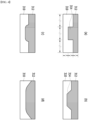
- Fig. 3 is a diagram for explaining the effect due to the opening shape of the inflow port of the chamber according to an embodiment of the present disclosure.
- the drying level of the electrode sheet 100 processed by the chamber 300 may be described as 'drying efficiency', but due to the various reasons described above, the drying efficiency of the electrode sheet 100 may vary depending on its position.
- the heat supplied to the central region of the electrode sheet 100 from a heater or the like located on the upper side of the electrode sheet 100 may be transferred from the central region to the peripheral region and then be discharged to the lower side of the electrode sheet 100.
- the peripheral region may additionally receive heat energy transferred from the central region to the peripheral region in addition to the heat energy transferred from the heating member, and a greater heat energy may be applied to the peripheral region than to the central region.
- heat energy is concentrated in the peripheral region in this way, drying of the peripheral region of the electrode sheet 100 can be performed faster than drying of the central region, and the drying efficiency of the central region may appear to be relatively lower than that of the peripheral region.
- the deviation in drying efficiency as described above may be caused by a deviation in the flow velocity or flow amount of the outside air flowing in through the inflow port 310.
- the deviation of drying efficiency may be promoted because the flow of outside air flowing in through the inflow port 310 is concentrated in the central region, or the flow velocity of the central region is slower than the flow velocity of the peripheral region.
- the outside air flowing in through the peripheral region of the inflow port 310 may be concentrated in the central region by diffraction, and the drying deviation may occur by reducing the heat energy that the outside air transfers to the central region.
- this deviation in drying efficiency can be minimized by adjusting the shape of the interrupting member 312. This may be because the opening shape of the inflow port 310 is formed differently by the interrupting member 312 and thereby, the flow of outside air is adjusted.
- the interrupting member 312 may be provided so that the heights of the central part and the peripheral part are different, and consequently, the outside air flowing into a specific region of the inflow port 310 can be interrupted.
- the interrupting member 312 may be provided so that the height of the central part is larger than the height of the peripheral part, and consequently, the outside air flowing into the central region of the inflow port 310 can be interrupted.
- the drying efficiency of the electrode sheet 100 may appear uniformly in the width direction as compared with Fig. 3(a), wherein the height may mean a length on the z-axis.
- the central part of the interrupting member 312 may be provided in a form protruding along the z-axis.
- the 'protruding shape' of the interrupting member 312 may be referred to as a protrusion part 314.
- the protrusion part 314 may refer to a portion having a large height value in of the interrupting member 312.
- the interrupting member 312 may change the flow of outside air flowing in through the inflow port 310.
- the height of the opening possessed by the inflow port 310 is changed by the interrupting member 312, whereby the flow velocity of the outside air flowing in through the inflow port 310 may change.
- the opening is narrowly formed in the region where the protrusion part 314 is provided, the flow amount in the corresponding region may decrease and the flow velocity may increase.
- the drying efficiency of the central region of the electrode sheet 100 corresponding to the protrusion part 314 may be improved.
- the outside air flowing in through the peripheral region of the inflow port 310 may be concentrated in the central region by diffraction, wherein if the interrupting member 312 is provided to cover the central region of the inflow port 310, the outside air can be distributed to the surrounding region, whereby the amount or velocity of the external air flowing in the width direction can be adjusted relatively evenly.
- the protrusion part 314 of the interrupting member 312 is formed in the central region of the inflow port 310 to improve the flow amount of outside air flowing into the peripheral region, whereby an effect of decreasing the temperature of the region around the slightly overheated electrode sheet 100 may appear.
- the electrode drying device 1 may be designed such that the protrusion part 314 is formed at a position corresponding to the second region, when a first heat energy transferred to a first region of the electrode sheet 100 in the chamber 300 is larger than a second heat energy transferred to a second region of the electrode sheet 100.
- the magnitude of the heat energy transferred to the first region and the second region may be calculated based on when there is no influence of outside air.
- the height of a first portion of the interrupting member 312 corresponding to the first region may be smaller than the height of a second portion of the interrupting member 312 corresponding to the second region.
- first region and the second region may be regions having different positions in the width direction of the electrode sheet 100, and when referring to the above description, the first region may be a peripheral region, and the second region may be a central region. Further, in this case, the first portion may be a peripheral part, and the second portion may be a central part. However, since this may vary depending on the design of the chamber 300, and the like, and thus, the first region can be the central region and the second region can be the peripheral region.
- a protrusion part 314 may be formed on the peripheral part of the interrupting member 312 in order to interrupt the outside air flowing into the peripheral region of the inflow port 310.
- Fig. 4 is a diagram showing examples of the opening shape of the inflow port of the chamber according to an embodiment of the present disclosure.
- the opening shape of the inflow port 310 is determined according to the shape of the interrupting member 312, whereby the flow amount or velocity of the outside air flowing into the chamber 300 is adjusted, so that the shape of the interrupting member 312 may be provided differently depending on the specifications or design of the electrode drying device.
- the protrusion part 314 of the interrupting member 312 may be provided so as to cover a region in which the height and width are divided equally into three, as shown in Fig. 4(a).
- the shape and position of the protrusion part 314 may be variously modified in consideration of various factors.
- the height of the protrusion part 314 formed on the interrupting member 312 may be determined according to the height at which the electrode sheet 100 enters, and the width of the protrusion part 314 may be appropriately designed in order to adjust the flow amount or flow velocity of outside air flowing into the central region and the peripheral region of the inflow port 310.
- the protrusion part 314 of the interrupting member 312 may be provided so that its side end forms an acute angle with the upper end 310a or the lower end 310b of the inflow port 310 as shown in Fig. 4(b), whereby the amount or velocity of the outside air flowing into the inflow port 310 may be more appropriately adjusted.
- the protrusion part 314 of the interrupting member 312 is formed so as to form a right angle with the upper end 310a or the lower end 310b as shown in Fig. 4 (a)
- the difference in the amount of outside air or the velocity of outside air between the region where the protrusion part 314 is located and the region where it is not located may be large, and a vortex or the like may be formed around the protrusion part 314.
- the drying deviation of the electrode sheet 100 may not be completely resolved, or the deviation may become larger.
- At least a part of the side end of the interrupting member 312 is preferably formed so as to form an acute angle with the upper end 310a or the lower end 310b of the inflow port 310.
- the protrusion part 314 of the interrupting member 312 may be provided so that the corner has a round shape as shown in Fig. 4(c) .
- Fig. 4(a) having an angled corner a phenomenon such as collision of outside air at the corner occurs, so that the inflow of outside air may be obstructed or the flow of outside air may change rapidly. Due to this, it may be difficult to completely solve the drying deviation of the electrode sheet 100, or the deviation in a specific part may become more severe. Therefore, it may be preferable that the corner of the protrusion part 314 formed on the interrupting member 312 has a round shape.
- the protrusion part 314 of the interrupting member 312 may be provided to have a large width as shown in Fig. 4(d) sol as interrupt the inflow of outside air in a wider range.
- the interrupting member 312 is shown in a shape symmetrical to each other on both sides, but this is not always the case, and when the supply of heat energy in the width direction inside the chamber 300 is nonuniform, the protrusion part 314 of the interrupting member 312 can be formed to be biased along the y-axis or the -y-axis. In this case, both sides of the protrusion part 314 may be formed to be different from each other.
Landscapes
- Engineering & Computer Science (AREA)
- Mechanical Engineering (AREA)
- General Engineering & Computer Science (AREA)
- Textile Engineering (AREA)
- Chemical & Material Sciences (AREA)
- Manufacturing & Machinery (AREA)
- Chemical Kinetics & Catalysis (AREA)
- Electrochemistry (AREA)
- General Chemical & Material Sciences (AREA)
- Materials Engineering (AREA)
- Battery Electrode And Active Subsutance (AREA)
Abstract
Description
- This application claims the benefit of
Korean Patent Application No. 10-2021-0030397 filed on March 8, 2021 Korean Patent Application No. 10-2022-0004898 filed on January 12, 2022 - The present disclosure relates to an electrode drying device, and more particularly, to an electrode drying device that removes moisture from an electrode sheet in a battery manufacturing process.
- Along with the technology development and increased demand for mobile devices, demand for secondary batteries as energy sources has been increasing rapidly. In particular, a secondary battery has attracted considerable attention as an energy source for power-driven devices, such as an electric bicycle, an electric vehicle, and a hybrid electric vehicle, as well as an energy source for mobile devices, such as a mobile phone, a digital camera, a laptop computer and a wearable device.
- The secondary battery may be classified based on the shape of a battery case into a cylindrical battery having an electrode assembly mounted in a cylindrical metal can, a prismatic battery having an electrode assembly mounted in a prismatic metal can, and a pouch type battery having an electrode assembly mounted in a pouch-shaped case made of a laminated aluminum sheet.
- Further, the secondary battery may be classified based on the structure of an electrode assembly having a structure in which a positive electrode and a negative electrode are stacked with a separator being interposed between the positive electrode and the negative electrode. Typically, there may be mentioned a jelly-roll (wound) type structure in which a long sheet type positive electrode and a long sheet type negative electrode are wound with a separator being interposed between the positive electrode and the negative electrode, a stacked (laminated) type structure in which pluralities of positive electrodes and negative electrodes, cut into predetermined unit sizes, are sequentially stacked with separators being interposed between the positive electrodes and the negative electrodes, or the like. In recent years, in order to solve problems caused by the jelly-roll type electrode assembly and the stacked type electrode assembly, there has been developed a stacked/folded type electrode assembly, which is a combination of the jelly-roll type electrode assembly and the stacked type electrode assembly.
- Meanwhile, as a method of manufacturing the electrode for a secondary battery, there are a method of dispersing an active material, a conductive material and/or a binder, etc. in a solvent to prepare a slurry, and then applying the slurry directly to a current collector to form the electrode, or a method of applying the slurry onto a separate support and laminating a film peeled from the support on a current collector to form the electrode.
- The electrode sheet formed by the above-mentioned method undergoes a drying process for removing residual solvent (NMP) or residual moisture, wherein the dry condition of the electrode sheet can greatly affect the quality of the battery. For example, the moisture remaining in the electrode sheet may reduce an oxidation-reduction reaction between the positive electrode and the negative electrode, whereby the rated energy of the battery may not be generated, or the charge/discharge cycle characteristics of the battery may be deteriorated. In another example, when moisture is present in the electrode sheet, the remaining moisture can react with the electrolyte to produce hydrogen fluoride, and the produced hydrogen fluoride may cause a decrease in ionic conductivity of the secondary battery, and a safety problem such as electrode corrosion.
- In the conventional electrode drying process, when an electrode sheet in a slurry state is inputted into a chamber through an inlet port formed on one surface of the chamber, a vacuum heating and drying method is mainly used in which the chamber is converted to a vacuum state and a heater or hot air system disposed in the chamber heats the airflow in the chamber, but in recent years, electrode high-speed running drying (Roll to Roll Drying, R2R Drying, hereinafter referred to as 'roll-to-roll') process is mainly used.
- The roll-to-roll process has an advantage in that a continuous process is possible by directly heating the electrode surface while running the electrode roll, but has a disadvantage in that nonuniform pressure gradient or temperature gradient may be generated in the chamber due to the inflow of air outside the chamber through an inlet port for inputting the electrode. If the pressure or temperature gradient inside the chamber is not uniform, a part of the electrode sheet is excessively dried, and a deviation in the dry condition may occur, which may cause the increase in the defect rate of the final product.
- It is an object of the present disclosure to provide an electrode drying device that can uniformly dry the electrode sheet, thereby improving the drying quality of the electrode slurry and minimizing the product defect rate.
- The objects of the present disclosure are not limited to the aforementioned objects, and other objects which are not described herein should be clearly understood by those skilled in the art from the following detailed description and the accompanying drawings.
- According to one embodiment of the present disclosure, there is provided an electrode drying device comprising: a transfer unit that transfers an electrode sheet having an electrode slurry coated onto the current collector, and a drying chamber including an inflow port where the electrode sheet transferred by the transfer unit enters, wherein an interrupting member for adjusting the flow amount or flow velocity of outside air flowing in a drying chamber is formed at the inflow port, and a height of a central part of the interrupting member is different from a height of a peripheral part of the interrupting member.
- The height of the central part is larger than the height of the peripheral part, and the central part may be a part different from the peripheral part including both ends in the width direction of the interrupting member.
- The drying chamber includes at least one heating element, and the interrupting member may be disposed at one end of the inflow port close to the heating member.
- At least one heating element is disposed at an upper part of the drying chamber, and when the electrode sheet is transferred to the lower part of the drying chamber by the transfer unit, the interrupting member may be disposed at an upper end of the inflow port close to the upper part of the drying chamber.
- When a first heat energy transferred to a first region of the electrode sheet in the drying chamber is larger than a second heat energy transferred to a second region of the electrode sheet, a height of the first portion of the interrupting member corresponding to the first region may be smaller than a height of a second portion of the interrupting member corresponding to the second region, and a position in the width direction of the first region in the electrode sheet may be different from a position in the width direction of the second region.
- The interrupting member includes a protrusion part, and a side end of the protrusion part is formed so as to form an acute angle with the upper end of the inflow port, and the protrusion part may refer to a portion having a larger height value in the interrupting member.
- The interrupting member includes a protrusion part, and a corner of the protrusion part has a round shape, and the protrusion part may refer to a portion having a larger height value in the interrupting member.
- The interrupting member may be integrated with the drying chamber.
- According to embodiments, the electrode drying device of the present disclosure can dry the electrode sheet uniformly, thereby reducing the product defect rate due to the deviation in the dry condition of the electrode sheet, and improving the uniformity or reliability of the product.
- The effects of the present disclosure are not limited to the effects mentioned above and additional other effects not described above will be clearly understood from the description of the appended claims by those skilled in the art.
-
-
Fig. 1 is a side view of an electrode drying device according to an embodiment of the present disclosure; -
Fig. 2 is a perspective view of a chamber according to an embodiment of the present disclosure; -
Fig. 3 is a diagram for explaining the effect due to the opening shape of the inflow port of the chamber according to an embodiment of the present disclosure; and -
Fig. 4 is a diagram showing examples of the opening shape of the inflow port of the chamber according to an embodiment of the present disclosure. - Hereinafter, various embodiments of the present disclosure will be described in detail with reference to the accompanying drawings so that those skilled in the art can easily carry out them. The present disclosure may be carried out in various different forms other than those described below, and the scope of the present disclosure is not limited by the embodiments described herein.
- Portions that are irrelevant to the description will be omitted to clearly describe the present disclosure, and like reference numerals designate like elements throughout the description.
- Further, in the drawings, the size and thickness of each element are arbitrarily illustrated for convenience of explanation, and the present disclosure is not necessarily limited to those illustrated in the drawings. In the drawings, the thickness of layers, regions, etc. are exaggerated for clarity. In the drawings, for convenience of explanation, the thicknesses of some layers and regions are exaggerated.
- In addition, it will be understood that when an element such as a layer, film, region, or plate is referred to as being "on" or "above" another element, it can be directly on the other element or intervening elements may also be present. In contrast, when an element is referred to as being "directly on" another element, it means that other intervening elements are not present. Further, the word "on" or "above" means disposed on or below a reference portion, and does not necessarily mean being disposed "on" or "above" the reference portion toward the opposite direction of gravity. Meanwhile, similar to the case where it is described as being located "on" or "above" another part, the case where it is described as being located "below" or "under" another part will also be understood with reference to the above-mentioned contents.
- Further, throughout the specification, when a portion is referred to as "including" or "comprising" a certain component, it means that the portion can further include other components, without excluding the other components, unless otherwise stated.
- Further, throughout the specification, when referred to as "planar", it means when a target portion is viewed from the upper side, and when referred to as "cross-sectional", it means when a target portion is viewed from the side of a cross section cut vertically.
- Now, an electrode drying device according to an embodiment of the present disclosure will be described.
-
Fig. 1 is a side view of an electrode drying device according to an embodiment of the present disclosure.Fig. 2 is a perspective view of a chamber according to an embodiment of the present disclosure. - Referring to
Figs. 1 and2 , the electrode drying device 1 according to an embodiment of the present disclosure includes atransfer unit 200 for transferring anelectrode sheet 100, and achamber 300 through which theelectrode sheet 100 transferred by thetransfer unit 200 passes. Here, the drying process of theelectrode sheet 100 may utilize a roll-to-roll process, and in the electrode drying process utilizing the roll-to-roll process, the electrode drying process of theelectrode sheet 100 can be continuously performed. - The
electrode sheet 100 may be an object of the electrode drying device 1. Theelectrode sheet 100 may be a long rectangular sheet in which an electrode slurry is coated onto a current collector. Here, as the current collector, stainless steel, aluminum, copper, nickel, titanium, calcined carbon, and the like can be used. The current collector can be provided in various forms such as a film, a sheet, a foil, a net, a porous body, a foam, a nonwoven fabric structure, and the like. Further, the electrode slurry herein may typically include an electrode active material, a conductive material, a binder, and a solvent, but is not limited thereto. - The
electrode sheet 100 may be either a positive electrode or a negative electrode. In one example, when theelectrode sheet 100 is a positive electrode, theelectrode sheet 100 can be manufactured by coating a positive electrode slurry including a positive electrode active material onto a positive electrode current collector. In another example, when theelectrode sheet 100 is a negative electrode, theelectrode sheet 100 can be manufactured by coating the negative electrode slurry including the negative electrode active material onto the negative electrode current collector. - The
transfer unit 200 may be for the purpose of supplying theelectrode sheet 100 into thechamber 300 and out of thechamber 300. Thetransfer unit 200 may include at least one roller for guiding the moving direction of theelectrode sheet 100 and/or a driving unit for driving the roller. Although not specifically shown in the figure, thetransfer unit 200 that supplies theelectrode sheet 100 to the inside of thechamber 300 may be referred to as an unwinder, and thetransfer unit 200 that recovers theelectrode sheet 100 to the outside of thechamber 300 may be referred to as a rewinder. - The
transfer unit 200 can adjust the moving speed of theelectrode sheet 100. Specifically, thetransfer unit 200 can adjust the time for which theelectrode sheet 100 stays in the electrode drying device 1, thereby adjusting the drying level of the electrode sheet. - The
chamber 300 may be for the purpose of providing a drying space that dries theelectrode sheet 100. Thechamber 300 may also be referred to as a drying chamber. Thechamber 300 may include aninflow port 310 where theelectrode sheet 100 enters and anoutflow port 320 where theelectrode sheet 100 exits. Thechamber 300 may continuously dry theelectrode sheet 100 moving from theinflow port 310 to theoutflow port 320 by a roll-to-roll process, through the drying space formed between theinflow port 310 and theoutflow port 320. - The
electrode sheet 100 can be moved from theinflow port 310 to theoutflow port 320 by thetransfer unit 200, and the transfer direction of theelectrode sheet 100 is shown by arrows inFig. 2 . Here, the longitudinal direction (x-axis direction) of theelectrode sheet 100 may be defined as a direction parallel to the transfer direction, and the width direction (y-axis direction) of theelectrode sheet 100 may be defined as a direction perpendicular to the above-mentioned longitudinal direction. - At least one heating member (not shown) may be disposed in the inside of the
chamber 300, and the airflow in thechamber 300 may be heated by the heating member, or theelectrode sheet 100 entering the inner space of thechamber 300 may be heated. Here, the heating member may be a hot air system including a heater, a nozzle/fan, or the like. The heater provided in thechamber 300 may be an IR (Infrared) heater, and may be provided in plural numbers. The drying efficiency and drying time of the electrode drying device 1 can be determined according to the arrangement and number of heating elements provided in thechamber 300. - The
chamber 300 may be filled with nitrogen (N2) gas or an inert gas such as argon or helium while being isolated from the outside. Since the internal temperature of thechamber 300 is maintained at a high temperature, the inside can be filled with the gas as described above, thereby preventing other chemical reactions such as an oxidation reaction from occurring in theelectrode sheet 100 passing through thechamber 300. Here, it may be preferable that thechamber 300 is filled with nitrogen gas that is inexpensive and is safe even if it leaks to the outside. - Meanwhile, the heating member such as a heater, a nozzle, or a fan disposed inside the
chamber 300 may be designed so that heat can be evenly transferred to theelectrode sheet 100, and specifically, it may be formed long along the width direction (y-axis direction) or may be arranged long. If a greater number of heating elements are provided in thechamber 300, it may be arranged in rows or columns along the longitudinal direction (x-axis direction). - However, even if the heating elements extend along the width direction or are arranged at equal intervals, the magnitude of heat energy transferred to the central region and the peripheral region of the
electrode sheet 100 may be different. For example, when one heating member is formed long along the width direction, the heat energy transferred to the central region of theelectrode sheet 100 may be larger than that of the peripheral region. In another example, when the heating member is a nozzle or a fan that supplies hot air, the hot air may be transferred to theelectrode sheet 100 and then move toward the edge (both ends in the y-axis direction) of theelectrode sheet 100, whereby heat energy transferred to the peripheral region of theelectrode sheet 100 may be larger than that of the central region. - Here, the central region may mean a central part in the width direction (y-axis direction), and the peripheral region may mean a peripheral part in the width direction (y-axis direction). Further, the central part herein may be a part including the center in the width direction, and the peripheral part may be a part including an edge in the width direction. For example, the central part may include a part located in the center when a specific part is divided equally into N, and the peripheral part may include parts located at both ends when a specific part is divided equally into N. In one example, the central part may be a part located in the center when a specific part is divided equally into three, and the peripheral part may be the remaining two parts excluding the part located in the center. Further, in the present disclosure, the central region may be referred to as a central part, and the peripheral region may be referred to as a peripheral part.
- The expressions such as the central region or the central part, the peripheral region or the peripheral part are not used only for the
electrode sheet 100, and for convenience of explanation, they can also be used for explaining theinflow port 310 or the interruptingmember 312 described later. - Further, as the inside of the
chamber 300 is filled with the above-mentioned inert gas or the like, the internal temperature and pressure of thechamber 300 may be maintained relatively constant, but outside air flows in or inside air flows out through the openedinflow port 310 andoutflow port 320, so that a temperature gradient or a pressure gradient inside thechamber 300 may change. Since the inflow of outside air or the outflow of inside air may be accompanied mainly by the movement of theelectrode sheet 100, the drying environment inside thechamber 300 may change depending on the shape of theinflow port 310 or theoutflow port 320, the speed at which theelectrode sheet 100 is moved by thetransfer unit 200, and the like. In particular, depending on the shape of theinflow port 310 or theoutflow port 320, the flow of outside air may be concentrated in the central region of theelectrode sheet 100 or may be concentrated in the peripheral region, and such a phenomenon may be accelerated according to the moving speed of theelectrode sheet 100. - In this manner, depending on the deviation of the heat energy transferred to the
electrode sheet 100 in thechamber 300 or a change in the drying environment inside thechamber 300, theelectrode sheet 100 may not be dried uniformly. As the deviation in the drying level of theelectrode sheet 100 is larger, the defective rate of the battery cell may more increase. - Referring to
Fig. 2 again, an interruptingmember 312 for adjusting the environment in thechamber 300 may be provided at theinflow port 310 of thechamber 300 according to the present embodiment. The interruptingmember 312 may also be referred to as a shield, a partition wall, a shade, a shutter, an awning, a cover, a screen, or the like. - Here, the interrupting
member 312 may be additionally provided to theinflow port 310 of thechamber 300, or may be integrated with one surface of thechamber 300 on which theinflow port 310 is formed. In other words, the interruptingmember 312 of the present disclosure is not a separate member, but may be mentioned to distinguish a part of thechamber 300 or theinflow port 310 in order to explain the shape of theinflow port 310 formed on one surface of thechamber 300. - The interrupting
member 312 can be for adjusting the opening shape of theinflow port 310 by covering a part of theinflow port 310. When the opening shape of theinflow port 310 is adjusted, the flow amount or flow velocity of outside air flowing into thechamber 300 may change, which may affect the drying environment in thechamber 300. - The interrupting
member 312 may be disposed at a position close to the heating member of thechamber 300. This may be for minimizing the deviation of heat energy due to outside air when the heating member provides heat to theelectrode sheet 100. For example, when the heating member is positioned in the upper part of thechamber 300 and theelectrode sheet 100 is moved in the lower part of thechamber 300, the interruptingmember 312 may be disposed at theupper end 310a of theinflow port 310 close to the upper part of thechamber 300. Here, the upper part or lower part of thechamber 300 refers to a relative position in a direction perpendicular to the coating surface of theelectrode sheet 100, and may not necessarily refer to a specific position. For convenience of explanation, the interruptingmember 312 will be described below based on the position of theupper end 310a and a part of theside end 310c of theinflow port 310, but the interruptingmember 312 can be positioned at thelower end 310b according to the embodiment. - Meanwhile, although not shown in the figure, the interrupting
member 312 may be provided so as to adjust the outflow of inside air by being positioned at a part of theupper end 320a, thelower end 320b or theside end 320c of theoutflow port 320. However, since the influence of theinflow port 310 on the drying environment of thechamber 300 may be larger than that of theoutflow port 320, the actual benefit obtained by providing the interruptingmember 312 at theoutflow port 320 may not be larger than when the interruptingmember 312 is provided at theinflow port 310. -
Fig. 3 is a diagram for explaining the effect due to the opening shape of the inflow port of the chamber according to an embodiment of the present disclosure. - The drying level of the
electrode sheet 100 processed by thechamber 300 may be described as 'drying efficiency', but due to the various reasons described above, the drying efficiency of theelectrode sheet 100 may vary depending on its position. - In a specific example, the heat supplied to the central region of the
electrode sheet 100 from a heater or the like located on the upper side of theelectrode sheet 100 may be transferred from the central region to the peripheral region and then be discharged to the lower side of theelectrode sheet 100. Thereby, the peripheral region may additionally receive heat energy transferred from the central region to the peripheral region in addition to the heat energy transferred from the heating member, and a greater heat energy may be applied to the peripheral region than to the central region. When heat energy is concentrated in the peripheral region in this way, drying of the peripheral region of theelectrode sheet 100 can be performed faster than drying of the central region, and the drying efficiency of the central region may appear to be relatively lower than that of the peripheral region. - Additionally, the deviation in drying efficiency as described above may be caused by a deviation in the flow velocity or flow amount of the outside air flowing in through the
inflow port 310. For example, the deviation of drying efficiency may be promoted because the flow of outside air flowing in through theinflow port 310 is concentrated in the central region, or the flow velocity of the central region is slower than the flow velocity of the peripheral region. Specifically, the outside air flowing in through the peripheral region of theinflow port 310 may be concentrated in the central region by diffraction, and the drying deviation may occur by reducing the heat energy that the outside air transfers to the central region. - When outside air is concentrated in a specific region of the
electrode sheet 100 or heat energy is concentrated, a deviation in the drying level may occur, and it may be difficult to show a constant drying efficiency in the width direction. This phenomenon may appear more remarkably when the opening shape of theinflow port 310 is formed into a rectangular shape and the height of theinflow port 310 is constant in the width direction as shown inFig. 3(a) . - Meanwhile, this deviation in drying efficiency can be minimized by adjusting the shape of the interrupting
member 312. This may be because the opening shape of theinflow port 310 is formed differently by the interruptingmember 312 and thereby, the flow of outside air is adjusted. - Referring to
Fig. 3(b) , the interruptingmember 312 according to an embodiment of the present disclosure may be provided so that the heights of the central part and the peripheral part are different, and consequently, the outside air flowing into a specific region of theinflow port 310 can be interrupted. The interruptingmember 312 may be provided so that the height of the central part is larger than the height of the peripheral part, and consequently, the outside air flowing into the central region of theinflow port 310 can be interrupted. Thereby, the drying efficiency of theelectrode sheet 100 may appear uniformly in the width direction as compared withFig. 3(a), wherein the height may mean a length on the z-axis. - The central part of the interrupting
member 312 may be provided in a form protruding along the z-axis. Here, the 'protruding shape' of the interruptingmember 312 may be referred to as aprotrusion part 314. In other words, theprotrusion part 314 may refer to a portion having a large height value in of the interruptingmember 312. - The interrupting
member 312 may change the flow of outside air flowing in through theinflow port 310. In one example, the height of the opening possessed by theinflow port 310 is changed by the interruptingmember 312, whereby the flow velocity of the outside air flowing in through theinflow port 310 may change. Specifically, since the opening is narrowly formed in the region where theprotrusion part 314 is provided, the flow amount in the corresponding region may decrease and the flow velocity may increase. As the flow velocity around theprotrusion part 314 increases, the drying efficiency of the central region of theelectrode sheet 100 corresponding to theprotrusion part 314 may be improved. - In another example, typically, the outside air flowing in through the peripheral region of the
inflow port 310 may be concentrated in the central region by diffraction, wherein if the interruptingmember 312 is provided to cover the central region of theinflow port 310, the outside air can be distributed to the surrounding region, whereby the amount or velocity of the external air flowing in the width direction can be adjusted relatively evenly. In yet another example, theprotrusion part 314 of the interruptingmember 312 is formed in the central region of theinflow port 310 to improve the flow amount of outside air flowing into the peripheral region, whereby an effect of decreasing the temperature of the region around the slightlyoverheated electrode sheet 100 may appear. By adjusting the opening shape of theinflow port 310 as shown inFig. 3(b) in this way, it is possible to change the flow of outside air flowing into thechamber 300, whereby a deviation in drying efficiency between the central region and the peripheral region of theelectrode sheet 100 can be reduced. - The electrode drying device 1 may be designed such that the
protrusion part 314 is formed at a position corresponding to the second region, when a first heat energy transferred to a first region of theelectrode sheet 100 in thechamber 300 is larger than a second heat energy transferred to a second region of theelectrode sheet 100. At this time, the magnitude of the heat energy transferred to the first region and the second region may be calculated based on when there is no influence of outside air. Here, the height of a first portion of the interruptingmember 312 corresponding to the first region may be smaller than the height of a second portion of the interruptingmember 312 corresponding to the second region. Further, the first region and the second region may be regions having different positions in the width direction of theelectrode sheet 100, and when referring to the above description, the first region may be a peripheral region, and the second region may be a central region. Further, in this case, the first portion may be a peripheral part, and the second portion may be a central part. However, since this may vary depending on the design of thechamber 300, and the like, and thus, the first region can be the central region and the second region can be the peripheral region. - On the other hand, assuming that the drying efficiency of the peripheral region is higher than that of the central region of the
electrode sheet 100, the case where theprotrusion part 314 is formed in the central part of the interruptingmember 312 is mainly described. - However, this is not always the case, and when the drying efficiency of the peripheral region is lower than that of the central region of the
electrode sheet 100, aprotrusion part 314 may be formed on the peripheral part of the interruptingmember 312 in order to interrupt the outside air flowing into the peripheral region of theinflow port 310. -
Fig. 4 is a diagram showing examples of the opening shape of the inflow port of the chamber according to an embodiment of the present disclosure. - As described above, the opening shape of the
inflow port 310 is determined according to the shape of the interruptingmember 312, whereby the flow amount or velocity of the outside air flowing into thechamber 300 is adjusted, so that the shape of the interruptingmember 312 may be provided differently depending on the specifications or design of the electrode drying device. - In one example, the
protrusion part 314 of the interruptingmember 312 may be provided so as to cover a region in which the height and width are divided equally into three, as shown inFig. 4(a). However, since this is only an example of the shape and position of theprotrusion part 314, the shape and position of theprotrusion part 314 may be variously modified in consideration of various factors. Specifically, the height of theprotrusion part 314 formed on the interruptingmember 312 may be determined according to the height at which theelectrode sheet 100 enters, and the width of theprotrusion part 314 may be appropriately designed in order to adjust the flow amount or flow velocity of outside air flowing into the central region and the peripheral region of theinflow port 310. - In another example, the
protrusion part 314 of the interruptingmember 312 may be provided so that its side end forms an acute angle with theupper end 310a or thelower end 310b of theinflow port 310 as shown inFig. 4(b), whereby the amount or velocity of the outside air flowing into theinflow port 310 may be more appropriately adjusted. - Specifically, when the
protrusion part 314 of the interruptingmember 312 is formed so as to form a right angle with theupper end 310a or thelower end 310b as shown inFig. 4 (a), the difference in the amount of outside air or the velocity of outside air between the region where theprotrusion part 314 is located and the region where it is not located may be large, and a vortex or the like may be formed around theprotrusion part 314. Thereby, the drying deviation of theelectrode sheet 100 may not be completely resolved, or the deviation may become larger. Therefore, when theprotrusion part 314 is formed on the interruptingmember 312, at least a part of the side end of the interruptingmember 312 is preferably formed so as to form an acute angle with theupper end 310a or thelower end 310b of theinflow port 310. - In another example, the
protrusion part 314 of the interruptingmember 312 may be provided so that the corner has a round shape as shown inFig. 4(c) . In the case ofFig. 4(a) having an angled corner, a phenomenon such as collision of outside air at the corner occurs, so that the inflow of outside air may be obstructed or the flow of outside air may change rapidly. Due to this, it may be difficult to completely solve the drying deviation of theelectrode sheet 100, or the deviation in a specific part may become more severe. Therefore, it may be preferable that the corner of theprotrusion part 314 formed on the interruptingmember 312 has a round shape. At this time, theprotrusion part 314 of the interruptingmember 312 may be provided to have a large width as shown inFig. 4(d) sol as interrupt the inflow of outside air in a wider range. - On the other hand, in the illustrative embodiments described above, the interrupting
member 312 is shown in a shape symmetrical to each other on both sides, but this is not always the case, and when the supply of heat energy in the width direction inside thechamber 300 is nonuniform, theprotrusion part 314 of the interruptingmember 312 can be formed to be biased along the y-axis or the -y-axis. In this case, both sides of theprotrusion part 314 may be formed to be different from each other. - The above description is only an example describing the scope of the technical idea of the present disclosure. Those skilled in the art will appreciate that various modifications and changes can be made without departing from the scope and spirit of the disclosure. Therefore, the embodiments of the present disclosure described above can be implemented independently or in combination with each other.
- The embodiments disclosed herein are intended to illustrate the scope of the technical idea of the present disclosure, and the scope of the present disclosure is not limited by the embodiments. The spirit and scope of the present disclosure should be interpreted construed on the basis of the appended claims, and all technical ideas within the same scope should be construed as being included in the scope of rights of the present disclosure.
-
- 100: electrode sheet
- 200: transfer unit
- 300: chamber
- 310: inflow port
- 312: interrupting member
- 320: outflow port
Claims (8)
- An electrode drying device comprising:a transfer unit that transfers an electrode sheet having an electrode slurry coated onto the current collector, anda drying chamber including an inflow port where the electrode sheet transferred by the transfer unit enters,wherein an interrupting member for adjusting the flow amount or flow velocity of outside air flowing in a drying chamber is formed at the inflow port, and a height of a central part of the interrupting member is different from a height of a peripheral part of the interrupting member.
- The electrode drying device of claim 1, wherein:the height of the central part is larger than the height of the peripheral part, andthe central part is a part different from the peripheral part including both ends in the width direction of the interrupting member.
- The electrode drying device of claim 1, wherein:
the drying chamber comprises at least one heating element, and the interrupting member is disposed at one end of the inflow port close to the heating member. - The electrode drying device of claim 1, wherein:
at least one heating element is disposed at an upper part of the drying chamber, and when the electrode sheet is transferred to the lower part of the drying chamber by the transfer unit, the interrupting member is disposed at an upper end of the inflow port close to the upper part of the drying chamber. - The electrode drying device of claim 1, wherein:when a first heat energy transferred to a first region of the electrode sheet in the drying chamber is larger than a second heat energy transferred to a second region of the electrode sheet,a height of the first portion of the interrupting member corresponding to the first region is smaller than a height of a second portion of the interrupting member corresponding to the second region, anda position in the width direction of the first region in the electrode sheet is different from a position in the width direction of the second region.
- The electrode drying device of claim 1, wherein:the interrupting member comprises a protrusion part, and a side end of the protrusion part is formed so as to form an acute angle with the upper end of the inflow port, andthe protrusion part refers to a portion having a larger height value in the interrupting member.
- The electrode drying device of claim 1, wherein:the interrupting member comprises a protrusion part, and a corner of the protrusion part has a round shape, andthe protrusion part refers to a portion having a larger height value in the interrupting member.
- The electrode drying device of claim 1, wherein:
the interrupting member is integrated with the drying chamber.
Applications Claiming Priority (3)
| Application Number | Priority Date | Filing Date | Title |
|---|---|---|---|
| KR20210030397 | 2021-03-08 | ||
| KR1020220004898A KR102910529B1 (en) | 2021-03-08 | 2022-01-12 | Electrode drying device |
| PCT/KR2022/000884 WO2022191411A1 (en) | 2021-03-08 | 2022-01-18 | Electrode drying device |
Publications (3)
| Publication Number | Publication Date |
|---|---|
| EP4187636A1 true EP4187636A1 (en) | 2023-05-31 |
| EP4187636A4 EP4187636A4 (en) | 2024-06-26 |
| EP4187636B1 EP4187636B1 (en) | 2025-05-07 |
Family
ID=83226834
Family Applications (1)
| Application Number | Title | Priority Date | Filing Date |
|---|---|---|---|
| EP22767308.4A Active EP4187636B1 (en) | 2021-03-08 | 2022-01-18 | Electrode drying device |
Country Status (7)
| Country | Link |
|---|---|
| US (1) | US20230366623A1 (en) |
| EP (1) | EP4187636B1 (en) |
| CN (1) | CN115997095B (en) |
| ES (1) | ES3032338T3 (en) |
| HU (1) | HUE071768T2 (en) |
| PL (1) | PL4187636T3 (en) |
| WO (1) | WO2022191411A1 (en) |
Family Cites Families (25)
| Publication number | Priority date | Publication date | Assignee | Title |
|---|---|---|---|---|
| US4591517A (en) * | 1984-06-08 | 1986-05-27 | Overly, Inc. | Web dryer with variable ventilation rate |
| JP2006221962A (en) * | 2005-02-10 | 2006-08-24 | Furukawa Battery Co Ltd:The | Method and apparatus for predrying electrode plate for lead storage battery |
| JPWO2009063824A1 (en) * | 2007-11-14 | 2011-03-31 | 富士フイルム株式会社 | Method for drying coating film and method for producing lithographic printing plate precursor |
| KR101461424B1 (en) * | 2009-11-30 | 2014-11-13 | 나노스캐일 컴포넌츠, 인코포레이티드 | Methods for producing textured electrode based energy storage device |
| JP5543869B2 (en) * | 2010-07-23 | 2014-07-09 | 日本碍子株式会社 | Electrode coating drying furnace for lithium ion batteries |
| KR101193169B1 (en) * | 2010-11-16 | 2012-10-19 | 삼성에스디아이 주식회사 | Apparatus and method for drying electrode plate |
| JP2012251763A (en) * | 2011-05-12 | 2012-12-20 | Sharp Corp | Apparatus and method for drying electrode |
| KR101475429B1 (en) * | 2012-05-15 | 2014-12-23 | 주식회사 엘지화학 | Flow Controller of Drying Oven with Automatic Air Charge for Manufacturing Secondary Battery |
| CN202700767U (en) * | 2012-05-31 | 2013-01-30 | 钟智帆 | Drying oven for heating and drying device of battery pole piece double-sided coating machine |
| KR20130136685A (en) * | 2012-06-05 | 2013-12-13 | 주식회사케이세라셀 | Drying apparatus of anode support for sofc and drying method using the same |
| CN103292586A (en) * | 2013-03-20 | 2013-09-11 | 温特牧(北京)科技有限公司 | Drying machine system |
| CN203304152U (en) * | 2013-05-10 | 2013-11-27 | 杨洪钧 | Electrode slice/battery cell dehydration drying device |
| CN204199029U (en) * | 2014-09-29 | 2015-03-11 | 张家港市华益纺织有限公司 | Be applicable to the oven dry coiling all-in-one of coated fabric |
| WO2017090934A1 (en) * | 2015-11-27 | 2017-06-01 | 한국기계연구원 | Substrate coating device and conductive - film coating device comprising same |
| KR102170897B1 (en) * | 2016-02-12 | 2020-10-28 | 주식회사 엘지화학 | Electrode Drying Device Comprising the Electrode Connection Equipment and Method of Restoring Electrode Substrate |
| KR102170893B1 (en) * | 2016-02-12 | 2020-10-28 | 주식회사 엘지화학 | Electrode Drying Oven For Manufacturing Secondary Battery |
| KR20170109912A (en) * | 2016-03-22 | 2017-10-10 | 삼성에스디아이 주식회사 | Apparatus for drying electrode plate |
| KR101810146B1 (en) * | 2016-07-21 | 2017-12-19 | (주)피엔티 | Dryer used in manufacturing electrode of secondary battery |
| CN206184712U (en) * | 2016-09-23 | 2017-05-24 | 惠州亿纬锂能股份有限公司 | A oven air outlet structure for making lithium ion battery cathode pole piece |
| KR102631007B1 (en) * | 2016-11-30 | 2024-01-29 | 엘지디스플레이 주식회사 | Substrate drying apparatus |
| KR101771632B1 (en) * | 2016-12-09 | 2017-08-25 | 한국진공주식회사 | Automatic in-line drying device for secondary battery plate |
| CN207563218U (en) * | 2017-11-10 | 2018-07-03 | 长沙佳纳锂业科技有限公司 | The hothouse of positive plate of lithium battery coating machine |
| KR102306546B1 (en) * | 2018-05-23 | 2021-09-30 | 주식회사 엘지에너지솔루션 | Notching device and method for secondary battery |
| CN210014633U (en) * | 2019-03-22 | 2020-02-04 | 南京啾又新能源电池有限公司 | Continuous water removal device for positive and negative pole pieces of lithium battery |
| KR102752344B1 (en) * | 2019-08-01 | 2025-01-10 | 주식회사 엘지에너지솔루션 | Dryer for electrode with water spraying unit and electrode drying method thereof |
-
2022
- 2022-01-18 CN CN202280005774.6A patent/CN115997095B/en active Active
- 2022-01-18 PL PL22767308.4T patent/PL4187636T3/en unknown
- 2022-01-18 HU HUE22767308A patent/HUE071768T2/en unknown
- 2022-01-18 EP EP22767308.4A patent/EP4187636B1/en active Active
- 2022-01-18 ES ES22767308T patent/ES3032338T3/en active Active
- 2022-01-18 US US18/026,497 patent/US20230366623A1/en active Pending
- 2022-01-18 WO PCT/KR2022/000884 patent/WO2022191411A1/en not_active Ceased
Also Published As
| Publication number | Publication date |
|---|---|
| WO2022191411A1 (en) | 2022-09-15 |
| PL4187636T3 (en) | 2025-07-07 |
| EP4187636A4 (en) | 2024-06-26 |
| ES3032338T3 (en) | 2025-07-17 |
| CN115997095A (en) | 2023-04-21 |
| HUE071768T2 (en) | 2025-09-28 |
| EP4187636B1 (en) | 2025-05-07 |
| US20230366623A1 (en) | 2023-11-16 |
| CN115997095B (en) | 2025-06-27 |
Similar Documents
| Publication | Publication Date | Title |
|---|---|---|
| KR101810146B1 (en) | Dryer used in manufacturing electrode of secondary battery | |
| EP4234105B1 (en) | Drying apparatus and coating device | |
| EP4238658A1 (en) | Coating apparatus | |
| EP1383197B1 (en) | Secondary battery manufacturing method and manufacturing device | |
| EP4258376B1 (en) | Electrode sheet drying apparatus capable of preventing thermal wrinkles in non-coated portion | |
| JP2015515736A (en) | Automatic air supply flow control device for electrode drying oven for secondary battery manufacturing | |
| JP2012097917A (en) | Drying device, and method for manufacturing electrode for secondary battery using the same | |
| KR20220095390A (en) | Secondary battery electrode manufacturing system and method | |
| CN115461886A (en) | Electrode drying device | |
| EP3147977B1 (en) | Apparatus for and method of manufacturing catalyst-coated membrane | |
| EP4187636B1 (en) | Electrode drying device | |
| KR102910529B1 (en) | Electrode drying device | |
| JP2015044132A (en) | Coating film forming device | |
| US20240355995A1 (en) | Electrode Manufacturing Device and Electrode Manufacturing Method Using Same | |
| KR100646550B1 (en) | Electrode plate of secondary battery and electrode plate coating apparatus of secondary battery | |
| EP4322240B1 (en) | Drying device with automatically adjustable shield film | |
| US20230282802A1 (en) | Manufacturing method and drying apparatus of electrode | |
| EP4328533A1 (en) | Electrode plate drying apparatus, battery production device, and electrode plate drying method | |
| KR20230053908A (en) | Electrode manufacture apparatus and method of manufacturing electrode using the same | |
| US20250121406A1 (en) | Electrode manufacturing apparatus and electrode manufacturing method | |
| CN105080810B (en) | Apparatus for drying electrode plate | |
| JP7859747B2 (en) | Apparatus and method for manufacturing electrodes | |
| KR102891251B1 (en) | Hybrid drying system for manufacturing secondary battery electrode | |
| US20240247870A1 (en) | Drying Apparatus, Electrode Plate Manufacturing Device, and Electrode Plate Drying Method | |
| US20250300157A1 (en) | Nozzle member and drying device including the same |
Legal Events
| Date | Code | Title | Description |
|---|---|---|---|
| STAA | Information on the status of an ep patent application or granted ep patent |
Free format text: STATUS: THE INTERNATIONAL PUBLICATION HAS BEEN MADE |
|
| PUAI | Public reference made under article 153(3) epc to a published international application that has entered the european phase |
Free format text: ORIGINAL CODE: 0009012 |
|
| STAA | Information on the status of an ep patent application or granted ep patent |
Free format text: STATUS: REQUEST FOR EXAMINATION WAS MADE |
|
| 17P | Request for examination filed |
Effective date: 20230221 |
|
| AK | Designated contracting states |
Kind code of ref document: A1 Designated state(s): AL AT BE BG CH CY CZ DE DK EE ES FI FR GB GR HR HU IE IS IT LI LT LU LV MC MK MT NL NO PL PT RO RS SE SI SK SM TR |
|
| DAV | Request for validation of the european patent (deleted) | ||
| DAX | Request for extension of the european patent (deleted) | ||
| A4 | Supplementary search report drawn up and despatched |
Effective date: 20240527 |
|
| RIC1 | Information provided on ipc code assigned before grant |
Ipc: F26B 25/06 20060101ALI20240521BHEP Ipc: F26B 15/12 20060101ALI20240521BHEP Ipc: H01M 4/04 20060101AFI20240521BHEP |
|
| GRAP | Despatch of communication of intention to grant a patent |
Free format text: ORIGINAL CODE: EPIDOSNIGR1 |
|
| STAA | Information on the status of an ep patent application or granted ep patent |
Free format text: STATUS: GRANT OF PATENT IS INTENDED |
|
| INTG | Intention to grant announced |
Effective date: 20250121 |
|
| P01 | Opt-out of the competence of the unified patent court (upc) registered |
Free format text: CASE NUMBER: APP_6069/2025 Effective date: 20250205 |
|
| GRAS | Grant fee paid |
Free format text: ORIGINAL CODE: EPIDOSNIGR3 |
|
| GRAA | (expected) grant |
Free format text: ORIGINAL CODE: 0009210 |
|
| STAA | Information on the status of an ep patent application or granted ep patent |
Free format text: STATUS: THE PATENT HAS BEEN GRANTED |
|
| AK | Designated contracting states |
Kind code of ref document: B1 Designated state(s): AL AT BE BG CH CY CZ DE DK EE ES FI FR GB GR HR HU IE IS IT LI LT LU LV MC MK MT NL NO PL PT RO RS SE SI SK SM TR |
|
| REG | Reference to a national code |
Ref country code: GB Ref legal event code: FG4D |
|
| REG | Reference to a national code |
Ref country code: CH Ref legal event code: EP |
|
| REG | Reference to a national code |
Ref country code: DE Ref legal event code: R096 Ref document number: 602022014419 Country of ref document: DE |
|
| REG | Reference to a national code |
Ref country code: IE Ref legal event code: FG4D |
|
| REG | Reference to a national code |
Ref country code: ES Ref legal event code: FG2A Ref document number: 3032338 Country of ref document: ES Kind code of ref document: T3 Effective date: 20250717 |
|
| REG | Reference to a national code |
Ref country code: NL Ref legal event code: MP Effective date: 20250507 |
|
| REG | Reference to a national code |
Ref country code: HU Ref legal event code: AG4A Ref document number: E071768 Country of ref document: HU |
|
| PG25 | Lapsed in a contracting state [announced via postgrant information from national office to epo] |
Ref country code: FI Free format text: LAPSE BECAUSE OF FAILURE TO SUBMIT A TRANSLATION OF THE DESCRIPTION OR TO PAY THE FEE WITHIN THE PRESCRIBED TIME-LIMIT Effective date: 20250507 Ref country code: PT Free format text: LAPSE BECAUSE OF FAILURE TO SUBMIT A TRANSLATION OF THE DESCRIPTION OR TO PAY THE FEE WITHIN THE PRESCRIBED TIME-LIMIT Effective date: 20250908 |
|
| REG | Reference to a national code |
Ref country code: LT Ref legal event code: MG9D |
|
| PG25 | Lapsed in a contracting state [announced via postgrant information from national office to epo] |
Ref country code: GR Free format text: LAPSE BECAUSE OF FAILURE TO SUBMIT A TRANSLATION OF THE DESCRIPTION OR TO PAY THE FEE WITHIN THE PRESCRIBED TIME-LIMIT Effective date: 20250808 Ref country code: NO Free format text: LAPSE BECAUSE OF FAILURE TO SUBMIT A TRANSLATION OF THE DESCRIPTION OR TO PAY THE FEE WITHIN THE PRESCRIBED TIME-LIMIT Effective date: 20250807 |
|
| PG25 | Lapsed in a contracting state [announced via postgrant information from national office to epo] |
Ref country code: NL Free format text: LAPSE BECAUSE OF FAILURE TO SUBMIT A TRANSLATION OF THE DESCRIPTION OR TO PAY THE FEE WITHIN THE PRESCRIBED TIME-LIMIT Effective date: 20250507 |
|
| REG | Reference to a national code |
Ref country code: AT Ref legal event code: MK05 Ref document number: 1793491 Country of ref document: AT Kind code of ref document: T Effective date: 20250507 |
|
| PG25 | Lapsed in a contracting state [announced via postgrant information from national office to epo] |
Ref country code: BG Free format text: LAPSE BECAUSE OF FAILURE TO SUBMIT A TRANSLATION OF THE DESCRIPTION OR TO PAY THE FEE WITHIN THE PRESCRIBED TIME-LIMIT Effective date: 20250507 |
|
| PG25 | Lapsed in a contracting state [announced via postgrant information from national office to epo] |
Ref country code: HR Free format text: LAPSE BECAUSE OF FAILURE TO SUBMIT A TRANSLATION OF THE DESCRIPTION OR TO PAY THE FEE WITHIN THE PRESCRIBED TIME-LIMIT Effective date: 20250507 |
|
| PG25 | Lapsed in a contracting state [announced via postgrant information from national office to epo] |
Ref country code: AT Free format text: LAPSE BECAUSE OF FAILURE TO SUBMIT A TRANSLATION OF THE DESCRIPTION OR TO PAY THE FEE WITHIN THE PRESCRIBED TIME-LIMIT Effective date: 20250507 |
|
| PG25 | Lapsed in a contracting state [announced via postgrant information from national office to epo] |
Ref country code: RS Free format text: LAPSE BECAUSE OF FAILURE TO SUBMIT A TRANSLATION OF THE DESCRIPTION OR TO PAY THE FEE WITHIN THE PRESCRIBED TIME-LIMIT Effective date: 20250807 |
|
| PG25 | Lapsed in a contracting state [announced via postgrant information from national office to epo] |
Ref country code: IS Free format text: LAPSE BECAUSE OF FAILURE TO SUBMIT A TRANSLATION OF THE DESCRIPTION OR TO PAY THE FEE WITHIN THE PRESCRIBED TIME-LIMIT Effective date: 20250907 |
|
| PG25 | Lapsed in a contracting state [announced via postgrant information from national office to epo] |
Ref country code: LV Free format text: LAPSE BECAUSE OF FAILURE TO SUBMIT A TRANSLATION OF THE DESCRIPTION OR TO PAY THE FEE WITHIN THE PRESCRIBED TIME-LIMIT Effective date: 20250507 |
|
| PGFP | Annual fee paid to national office [announced via postgrant information from national office to epo] |
Ref country code: GB Payment date: 20251222 Year of fee payment: 5 |
|
| PG25 | Lapsed in a contracting state [announced via postgrant information from national office to epo] |
Ref country code: SM Free format text: LAPSE BECAUSE OF FAILURE TO SUBMIT A TRANSLATION OF THE DESCRIPTION OR TO PAY THE FEE WITHIN THE PRESCRIBED TIME-LIMIT Effective date: 20250507 Ref country code: DK Free format text: LAPSE BECAUSE OF FAILURE TO SUBMIT A TRANSLATION OF THE DESCRIPTION OR TO PAY THE FEE WITHIN THE PRESCRIBED TIME-LIMIT Effective date: 20250507 |
|
| PGFP | Annual fee paid to national office [announced via postgrant information from national office to epo] |
Ref country code: FR Payment date: 20251223 Year of fee payment: 5 |
|
| PGFP | Annual fee paid to national office [announced via postgrant information from national office to epo] |
Ref country code: BE Payment date: 20251229 Year of fee payment: 5 |
|
| PG25 | Lapsed in a contracting state [announced via postgrant information from national office to epo] |
Ref country code: CZ Free format text: LAPSE BECAUSE OF FAILURE TO SUBMIT A TRANSLATION OF THE DESCRIPTION OR TO PAY THE FEE WITHIN THE PRESCRIBED TIME-LIMIT Effective date: 20250507 |
|
| PG25 | Lapsed in a contracting state [announced via postgrant information from national office to epo] |
Ref country code: EE Free format text: LAPSE BECAUSE OF FAILURE TO SUBMIT A TRANSLATION OF THE DESCRIPTION OR TO PAY THE FEE WITHIN THE PRESCRIBED TIME-LIMIT Effective date: 20250507 |
|
| PG25 | Lapsed in a contracting state [announced via postgrant information from national office to epo] |
Ref country code: SK Free format text: LAPSE BECAUSE OF FAILURE TO SUBMIT A TRANSLATION OF THE DESCRIPTION OR TO PAY THE FEE WITHIN THE PRESCRIBED TIME-LIMIT Effective date: 20250507 |
|
| PG25 | Lapsed in a contracting state [announced via postgrant information from national office to epo] |
Ref country code: IT Free format text: LAPSE BECAUSE OF FAILURE TO SUBMIT A TRANSLATION OF THE DESCRIPTION OR TO PAY THE FEE WITHIN THE PRESCRIBED TIME-LIMIT Effective date: 20250507 |
|
| REG | Reference to a national code |
Ref country code: DE Ref legal event code: R097 Ref document number: 602022014419 Country of ref document: DE |
|
| PGFP | Annual fee paid to national office [announced via postgrant information from national office to epo] |
Ref country code: HU Payment date: 20260129 Year of fee payment: 5 |
|
| PLBE | No opposition filed within time limit |
Free format text: ORIGINAL CODE: 0009261 |
|
| STAA | Information on the status of an ep patent application or granted ep patent |
Free format text: STATUS: NO OPPOSITION FILED WITHIN TIME LIMIT |
|
| REG | Reference to a national code |
Ref country code: CH Ref legal event code: L10 Free format text: ST27 STATUS EVENT CODE: U-0-0-L10-L00 (AS PROVIDED BY THE NATIONAL OFFICE) Effective date: 20260318 |
|
| PGFP | Annual fee paid to national office [announced via postgrant information from national office to epo] |
Ref country code: ES Payment date: 20260212 Year of fee payment: 5 |
|
| PGFP | Annual fee paid to national office [announced via postgrant information from national office to epo] |
Ref country code: DE Payment date: 20251222 Year of fee payment: 5 |
|
| 26N | No opposition filed |
Effective date: 20260210 |
|
| PGFP | Annual fee paid to national office [announced via postgrant information from national office to epo] |
Ref country code: PL Payment date: 20251229 Year of fee payment: 5 |