EP4187561A1 - Core, rotating electrical machine, and stationary apparatus - Google Patents
Core, rotating electrical machine, and stationary apparatus Download PDFInfo
- Publication number
- EP4187561A1 EP4187561A1 EP21875659.1A EP21875659A EP4187561A1 EP 4187561 A1 EP4187561 A1 EP 4187561A1 EP 21875659 A EP21875659 A EP 21875659A EP 4187561 A1 EP4187561 A1 EP 4187561A1
- Authority
- EP
- European Patent Office
- Prior art keywords
- friction
- friction area
- core
- area
- pair
- Prior art date
- Legal status (The legal status is an assumption and is not a legal conclusion. Google has not performed a legal analysis and makes no representation as to the accuracy of the status listed.)
- Pending
Links
Images

Classifications
-
- H—ELECTRICITY
- H02—GENERATION; CONVERSION OR DISTRIBUTION OF ELECTRIC POWER
- H02K—DYNAMO-ELECTRIC MACHINES
- H02K1/00—Details of the magnetic circuit
- H02K1/06—Details of the magnetic circuit characterised by the shape, form or construction
- H02K1/12—Stationary parts of the magnetic circuit
- H02K1/20—Stationary parts of the magnetic circuit with channels or ducts for flow of cooling medium
-
- H—ELECTRICITY
- H02—GENERATION; CONVERSION OR DISTRIBUTION OF ELECTRIC POWER
- H02K—DYNAMO-ELECTRIC MACHINES
- H02K1/00—Details of the magnetic circuit
- H02K1/06—Details of the magnetic circuit characterised by the shape, form or construction
- H02K1/12—Stationary parts of the magnetic circuit
-
- F—MECHANICAL ENGINEERING; LIGHTING; HEATING; WEAPONS; BLASTING
- F25—REFRIGERATION OR COOLING; COMBINED HEATING AND REFRIGERATION SYSTEMS; HEAT PUMP SYSTEMS; MANUFACTURE OR STORAGE OF ICE; LIQUEFACTION SOLIDIFICATION OF GASES
- F25B—REFRIGERATION MACHINES, PLANTS OR SYSTEMS; COMBINED HEATING AND REFRIGERATION SYSTEMS; HEAT PUMP SYSTEMS
- F25B31/00—Compressor arrangements
- F25B31/02—Compressor arrangements of motor-compressor units
- F25B31/026—Compressor arrangements of motor-compressor units with compressor of rotary type
-
- H—ELECTRICITY
- H01—ELECTRIC ELEMENTS
- H01F—MAGNETS; INDUCTANCES; TRANSFORMERS; SELECTION OF MATERIALS FOR THEIR MAGNETIC PROPERTIES
- H01F3/00—Cores, Yokes, or armatures
- H01F3/02—Cores, Yokes, or armatures made from sheets
-
- H—ELECTRICITY
- H02—GENERATION; CONVERSION OR DISTRIBUTION OF ELECTRIC POWER
- H02K—DYNAMO-ELECTRIC MACHINES
- H02K1/00—Details of the magnetic circuit
- H02K1/06—Details of the magnetic circuit characterised by the shape, form or construction
- H02K1/12—Stationary parts of the magnetic circuit
- H02K1/18—Means for mounting or fastening magnetic stationary parts on to, or to, the stator structures
- H02K1/185—Means for mounting or fastening magnetic stationary parts on to, or to, the stator structures to outer stators
Definitions
- the present disclosure relates to a core, a rotating electrical machine, and a stationary apparatus.
- Patent Document 1 discloses a motor including a stator and a rotor.
- the stator includes a stator core (as a core)
- the rotor includes a rotor core (as a core).
- an air gap is left between the stator core and the rotor core.
- Patent Document 1 Japanese Unexamined Patent Publication No. 2019-180160
- torque is generated by an electromagnetic force acting on the air gap.
- the electromagnetic force acting on the air gap may oscillate the cores of the stator and the rotor.
- the oscillation of the cores is transmitted to holding members that hold the cores, which may oscillate the holding members and generate noise.
- a first aspect of the present disclosure is directed to a core including:
- the first and second friction areas (F1) and (F2) with different friction coefficients can be located at portions that oscillate in different amounts of oscillation when the pair of electrical steel sheets are excited, in order to provide an attenuation effect. It is therefore possible to reduce the oscillations of the core (11, 21).
- a second aspect of the present disclosure is the core (11, 21) of the first aspect, wherein
- the second friction area (F2) with a smaller friction coefficient than the first friction area (F1) is located in the second oscillating portion (V2) that oscillates in a greater amount of oscillation than the first oscillating portion (V1). This configuration further attenuates the oscillations of the pair of electrical steel sheets.
- a third aspect of the present disclosure is the core (11, 21) of the first or second aspect, further including:
- the amount of oscillation of the pair of electrical steel sheets is smaller in a portion close to the fastener (13) than in a portion away from the fastener (13).
- the oscillations of the pair of electrical steel sheets are further attenuated since the first friction area (F1) is closer to the fastener (13) than the second friction area (F2) is.
- a fourth aspect of the present disclosure is the core (11, 21) of any one of the first to third aspects, wherein
- the amount of oscillation of the pair of electrical steel sheets is greater in a portion away from the holding member (4, 2a) than in a portion close to the holding member (4, 2a).
- the distance between the second friction area (F2) and the holding member (4, 2a) is longer than the distance between the first friction area (F1) and the holding member (4, 2a), which further attenuates the oscillations of the pair of electrical steel sheets.
- a fifth aspect of the present disclosure is the core (11, 21) of any one of the first to fourth aspects, wherein
- At least one of the first friction area (F1) or the second friction area (F2) is located on the surface member (30), thereby making it possible for the first and second friction areas (F1) and (F2) to have different friction coefficients.
- a sixth aspect of the present disclosure is the core (11, 21) of any one of the first to fifth aspects, wherein the first friction area (F1) and the second friction area (F2) of the pair of electrical steel sheets differ from each other in surface roughness.
- the surface roughness differs between the first friction area (F1) and the second friction area (F2), thereby making it possible for the first friction area (F1) and the second friction area (F2) to have different friction coefficients.
- a seventh aspect of the present disclosure is directed to a rotating electrical machine including the core (11, 21) of any one of the first to sixth aspects.
- An eighth aspect of the present disclosure is directed to a stationary apparatus including the core (11, 21) of any one of the first to sixth aspects.
- FIG. 1 shows a compressor (1) according to a first embodiment.
- the compressor (1) is disposed, for example, in a refrigerant circuit (not shown) of an air conditioner.
- the compressor (1) compresses a refrigerant in the refrigerant circuit.
- the compressor (1) includes a motor (2), a compression mechanism (3), and a casing (4).
- the casing (4) is a container that houses the compression mechanism (3) and the motor (2).
- the casing (4) is a holding member that holds a stator (10) of the motor (2).
- the casing (4) is a closed container.
- the casing (4) is made of metal, such as iron.
- the casing (4) is formed, for example, by forming a cylindrical member by so-called “roll bending" a sheet metal (e.g., a sheet of a material such as iron) and welding end plates (e.g., metal, such as iron) to both ends of the cylindrical member.
- the compression mechanism (3) compresses a fluid (a refrigerant in this example).
- the compression mechanism (3) may be any one of various fluid machines.
- the compression mechanism (3) may be a rotary compression mechanism, a scroll compression mechanism, or any other suitable mechanism.
- the compression mechanism (3) takes a fluid in from an intake pipe (3a) provided in a side surface of the casing (4) and discharges the compressed fluid into the casing (4).
- the fluid (i.e., refrigerant) discharged into the casing (4) is discharged through a discharge pipe (3b).
- the motor (2) is an example of a rotating electrical machine.
- the motor (2) drives the compression mechanism (3).
- the motor (2) is a magnet embedded type rotating electrical machine.
- the motor (2) includes the stator (10), a rotor (20), and a shaft (2a).
- the shaft (2a) is a holding member that holds the rotor (20).
- the shaft (2a) is made of metal, such as iron.
- the shaft (2a) is connected to the compression mechanism (3) as well.
- an axial direction corresponds to the direction in which the center of the shaft (2a) extends.
- a radial direction is orthogonal to the axial direction.
- a circumferential direction extends along a circle around the center of the shaft (2a).
- the rotor (20) includes a rotor core (21) and a permanent magnet (not shown).
- the permanent magnet is housed in a through hole in the rotor core (21).
- the rotor core (21) includes a laminated body (22).
- the laminated body (22) is a cylindrical member.
- the laminated body (22) is formed by stacking a large number of plate members (hereinafter referred to as "rotor plates (23)") in the axial direction.
- the rotor core (21) is a so-called laminated core.
- the rotor plates (23) are electrical steel sheets.
- the rotor plates (23) are manufactured by pressing electrical steel sheets, for example.
- the rotor plates (23) are coated with an insulating film.
- the rotor core (21) is manufactured by fixing the rotor plates (23) to each other through crimping, for example.
- Each rotor plate (23) has, at its center, a through hole for inserting the shaft (2a).
- the stator (10) includes the stator core (11) and a coil (16).
- the stator core (11) corresponds to the "core” according to the present disclosure.
- the stator core (11) includes a laminated body (12) and a fastener (13).
- the laminated body (12) is a cylindrical member.
- the laminated body (12) is formed by stacking a large number of plate members (hereinafter referred to as "stator plates (17)”) in the axial direction. In other words, the stator plates (17) are stacked in a direction substantially parallel to the axial direction.
- the stator core (11) is a so-called "laminated core".
- the stator plates (17) are electrical steel sheets.
- the stator plate (17) are manufactured by pressing electrical steel sheets, for example.
- the stator plates (17) are coated with an insulating film.
- the stator core (11) is manufactured by fastening the stator plates (17) to each other with a bolt.
- the bolt serves as the fastener (13).
- the fastener (13) fastens a pair of adjacent electrical steel sheets.
- the stator plates (17) may be fastened to each other by crimping or welding.
- the laminated body (12) has a plurality of contact areas (C).
- Each contact area (C) is interposed between a pair of adjacent stator plates (17, 17) of the laminated body (12).
- each contact area (C) is interposed between a pair of adjacent electrical steel sheets among the plurality of electrical steel sheets.
- the contact areas (C) include direct contact areas (D) and a plurality of friction areas (F1, F2).
- D direct contact areas
- F1, F2 friction areas
- the friction areas (F1, F2) have different friction coefficients from the direct contact areas (D).
- the plurality of friction areas (F1, F2) have friction coefficients different from each other.
- the "friction coefficients" used herein include coefficients of static friction and dynamic friction.
- the plurality of friction areas (F1, F2) includes a first friction area (F1) and a second friction area (F2).
- the respective friction coefficients of the friction areas (F1, F2) are measured in accordance with JIS K7125: 1999.
- the first friction area (F1) is located around the fastener (13).
- the first friction area (F1) surrounds the fastener (13) at a predetermined distance from the fastener (13).
- the second friction area (F2) is farther from the fastener (13) than the first friction area (F1) is.
- the shortest distance between the fastener (13) and the first friction area (F1) is a first distance L1
- the shortest distance between the fastener (13) and the second friction area (F2) is a second distance L2.
- the second distance L2 is longer than the first distance L1 (i.e., L1 ⁇ L2).
- the first friction area (F1) is closer to the fastener (13) than the second friction area (F2) is.
- Each first friction area is in a ring shape with a width (i.e., length in the radial direction) d1.
- Each second friction area (F2) is formed in a band shape with a width d2.
- the widths d1 of the first friction areas (F1) in the respective contact areas (C) are the same.
- the widths d2 of the respective second friction areas (F2) in the contact areas (C) are also the same.
- the plurality of first friction areas (F1) overlap each other in the stacking direction, and the plurality of second friction areas (F2) overlap each other in the stacking direction.
- each pair of stator plates (17, 17) is provided with a surface member (30) on its surface.
- the lower one of the pair of stator plates (17, 17) is provided with a first surface member (31) and a second surface member (32) on its surface.
- the first surface member (31) is made of rubber.
- the second surface member (32) is made of resin.
- the first friction area (F1) is interposed between the first surface member (31) and the stator plate (17).
- the second friction area (F2) is interposed between the second surface member (32) and the stator plate (17).
- the friction coefficient ⁇ 2 of the second friction area (F2) is smaller than the friction coefficient ⁇ 1 of the first friction area (F1) (i.e., ⁇ 1 > ⁇ 2).
- each contact area (C) includes the plurality of friction areas (F1, F2) with different friction coefficients. Accordingly, when the pair of stator plates (17, 17) oscillate, the portions of the pair of stator plates (17, 17) forming the friction areas (F1, F2) move in different amounts in the shear direction.
- the friction coefficient ⁇ 2 of the second friction area (F2) is smaller than the friction coefficient ⁇ 1 of the first friction area (F1) (i.e., ⁇ 1 > ⁇ 2). Accordingly, the stator plates (17) are less likely to move with respect to the first surface member (31) in the first friction area (F1) in the shear direction, and more likely to move with respect to the second surface member (32) in the second friction area (F2) in the shear direction.
- Oscillation of the laminated body (12) causes a pair of adjacent stator plates (17, 17) to oscillate in a predetermined amount of oscillation in the periphery of the fastener (13).
- the stator plates (17) are not fixed to each other in a portion away from the fastener (13) and hence oscillate in a greater amount of oscillation than in a first oscillating portion (V1).
- the periphery of the fastener (13), where the stator plates (17, 17) oscillate in a predetermined amount of oscillation, is regarded as the first oscillating portion (V1), and the portion that is away from the fastener (13) and oscillates in a greater amount of oscillation than in the first oscillating portion (V1) is regarded as a second oscillating portion (V2).
- the first friction area (F1) is formed in the first oscillating portion (V1)
- the second friction area (F2) is formed in the second oscillating portion (V2).
- the stator plates (17) can move in a greater amount with respect to the second surface member (32) in the second oscillating portion (V2). Accordingly, the oscillation energy at the second oscillating portion (V2) can be converted into the thermal energy caused by friction, which can further attenuate the oscillations of the pair of stator plates (17, 17).
- Feature (1) of this embodiment is that the contact area (C) includes a first friction area (F1) and a second friction area (F2) with friction coefficients different from each other.
- the first and second friction areas (F1) and (F2) with different friction coefficients can be located at portions that oscillate in different amounts of oscillation when the pair of stator plates (17, 17) are excited, in order to provide an attenuation effect. It is therefore possible to reduce the oscillations of the stator core (11).
- Feature (2) of this embodiment is that the pair of stator plates (17, 17) include: a first oscillating portion (V1) that oscillates in a predetermined amount of oscillation when excited; and a second oscillating portion (V2) that oscillates in a greater amount of oscillation than the first oscillating portion (V1), that the first friction area (F1) is located in the first oscillating portion (V1), that the second friction area (F2) is located in the second oscillating portion (V2), and that the second friction area (F2) has a smaller friction coefficient than the first friction area (F1).
- V1 first oscillating portion
- V2 second oscillating portion
- the second friction area (F2) with a smaller friction coefficient than the first friction area (F1) is located in the second oscillating portion (V2) that oscillates in a greater amount of oscillation than the first oscillating portion (V1).
- the amount of movement of the stator plates (17) is greater in the second oscillating portion (V2) than in the first oscillating portion (V1). Accordingly, the oscillation energy at the second oscillating portion (V2) can be converted into the thermal energy caused by friction, which further attenuates the oscillations of the pair of stator plates (17, 17).
- Feature (3) of this embodiment is that the first friction area (F1) is closer to the fastener (13) than the second friction area (F2) is.
- the amount of oscillation of the pair of stator plates (17, 17) is smaller in a portion close to the fastener (13) than in a portion away from the fastener (13).
- the oscillations of the pair of the stator plates (17, 17) are further attenuated since the first friction area (F1) is closer to the fastener (13) than the second friction area (F2) is.
- Feature (4) of this embodiment is that at least one of the pair of stator plates (17, 17) is provided with a surface member (30) on a surface thereof, and at least one of the first friction area (F1) or the second friction area (F2) is located on the surface member (30).
- At least one of the first friction area (F1) or the second friction area (F2) is located on the surface member (30). This configuration can attenuate the oscillations of the pair of stator plates (17, 17).
- the first friction area (F1) may be located near the casing (4).
- the laminated body (12) of the stator core (11) is held by the casing (4).
- the first friction area (F1) extends in the circumferential direction along the casing (4) at a predetermined distance from the inner circumferential surface of the casing (4) in the radial direction.
- the second friction area (F2) is farther from the casing (4) than the first friction area (F1) is.
- the second friction area (F2) extends in the circumferential direction at a predetermined distance from the first friction area (F1) in the radial direction.
- the distance L2 between the second friction area (F2) and the casing (4) is longer than the distance L1 between the first friction area (F1) and the casing (4) (i.e., L1 ⁇ L2).
- oscillation of the laminated body (12) causes a pair of stator plates (17, 17) to oscillate in a predetermined amount of oscillation in the vicinity of the casing (4) holding the laminated body (12) (i.e., in the first oscillating portion (V1)).
- the stator plates (17) can move relative to each other in a portion away from the casing (4) (i.e., in the second oscillating portion (V2)) and thus oscillate in a greater amount of oscillation than in the first oscillating portion (V1).
- the stator plates (17) can move in a greater amount with respect to the second surface member (32) in the second oscillating portion (V2). Accordingly, the oscillation energy at the second oscillating portion (V2) can be converted into the thermal energy caused by friction, which can further attenuate the oscillations of the pair of stator plates (17, 17).
- the surface member (30) may be an adhesive, varnish, a coating agent applied to the surfaces of the stator plates (17), or any other suitable substances.
- the configuration according to this variation to, can attenuate the oscillations of the pair of stator plates (17, 17).
- the surface roughness may differ between the first and second friction areas (F1) and (F2) of a pair of stator plates (17, 17).
- At least one of the friction areas (F1, F2) may be produced by applying a surface finish to at least one of the pair of stator plates (17, 17) to change the roughness of the surface.
- a surface finish may be applied to the stator plate (17) to change the surface roughness.
- At least one of the pair of stator plates (17, 17) may have fine asperities on a surface in the first friction area (F1) or the second friction area (F2).
- a surface of at least one of the pair of stator plates (17, 17) may be mirror finished.
- the surface roughness is an arithmetic average roughness (Ra).
- the surface roughness is measured in this variation using a contact surface roughness tester.
- the second friction area (F2) has a smaller arithmetic average roughness than the first friction area (F1).
- the surface roughness differs between the first friction area (F1) and the second friction area (F2), thereby making it possible for the first friction area (F1) and the second friction area (F2) to have different friction coefficients.
- stator plates (17) may be fixed to each other by crimping.
- the crimped part serves as the fastener (13) of the present disclosure.
- the fastener (13) and the first friction area (F1) may be in contact with each other.
- the first distance L1 which is the shortest distance between the fastener (13) and the first friction area (F1), may be zero.
- the first friction area (F1) and the second friction area (F2) may be in contact with each other.
- the widths d1 of the first friction areas (F1) in the respective contact areas (C) are not necessarily the same.
- the widths d2 of the respective second friction areas (F2) are not necessarily the same.
- some of the plurality of contact areas (C) may have a plurality of friction areas (F1, F2).
- the configuration of the contact areas (C) according to the embodiment described above may be applied to the rotor core (21).
- the shaft (2a) corresponds to the "holding member” according to the present disclosure.
- the configuration of the contact areas (C) may be applied to a generator.
- the configuration of the contact areas (C) according to the embodiment described above may be applied to a stationary apparatus.
- the present disclosure is useful for a core, a rotating electrical machine, and a stationary apparatus.
Landscapes
- Engineering & Computer Science (AREA)
- Power Engineering (AREA)
- Physics & Mathematics (AREA)
- Mechanical Engineering (AREA)
- Thermal Sciences (AREA)
- General Engineering & Computer Science (AREA)
- Iron Core Of Rotating Electric Machines (AREA)
Abstract
Description
- The present disclosure relates to a core, a rotating electrical machine, and a stationary apparatus.
- Rotating electrical machines, such as motors and generators, have been known. Patent Document 1 discloses a motor including a stator and a rotor. According to Patent Document 1, the stator includes a stator core (as a core), and the rotor includes a rotor core (as a core). In the motor according to Patent Document 1, an air gap is left between the stator core and the rotor core.
- Patent Document 1:
Japanese Unexamined Patent Publication No. 2019-180160 - In the motor according to Patent Document 1, torque is generated by an electromagnetic force acting on the air gap. The electromagnetic force acting on the air gap may oscillate the cores of the stator and the rotor. The oscillation of the cores is transmitted to holding members that hold the cores, which may oscillate the holding members and generate noise.
- It is an object of the present disclosure to reduce the oscillations of a core.
- A first aspect of the present disclosure is directed to a core including:
- a laminated body (12, 22) including a plurality of electrical steel sheets stacked one on another;
- the laminated body (12, 22) including a contact area (C) between a pair of adjacent electrical steel sheets of the plurality of electrical steel sheets,
- the contact area (C) including a first friction area (F1) and a second friction area (F2) with friction coefficients different from each other.
- According to the first aspect, the first and second friction areas (F1) and (F2) with different friction coefficients can be located at portions that oscillate in different amounts of oscillation when the pair of electrical steel sheets are excited, in order to provide an attenuation effect. It is therefore possible to reduce the oscillations of the core (11, 21).
- A second aspect of the present disclosure is the core (11, 21) of the first aspect, wherein
- the pair of electrical steel sheets include: a first oscillating portion (V1) that oscillates in a predetermined amount of oscillation when excited; and a second oscillating portion (V2) that oscillates in a greater amount of oscillation than the first oscillating portion (V1),
- the first friction area (F1) is located in the first oscillating portion (V1),
- the second friction area (F2) is located in the second oscillating portion (V2), and
- the second friction area (F2) has a smaller friction coefficient than the first friction area (F1).
- According to the second aspect, the second friction area (F2) with a smaller friction coefficient than the first friction area (F1) is located in the second oscillating portion (V2) that oscillates in a greater amount of oscillation than the first oscillating portion (V1). This configuration further attenuates the oscillations of the pair of electrical steel sheets.
- A third aspect of the present disclosure is the core (11, 21) of the first or second aspect, further including:
- a fastener (13) configured to fasten the pair of electrical steel sheets, wherein
- the first friction area (F1) is closer to the fastener (13) than the second friction area (F2) is, and
- the second friction area (F2) has a smaller friction coefficient than the first friction area (F1).
- According to the third aspect, the amount of oscillation of the pair of electrical steel sheets is smaller in a portion close to the fastener (13) than in a portion away from the fastener (13). The oscillations of the pair of electrical steel sheets are further attenuated since the first friction area (F1) is closer to the fastener (13) than the second friction area (F2) is.
- A fourth aspect of the present disclosure is the core (11, 21) of any one of the first to third aspects, wherein
- the laminated body (12, 22) is held by a holding member (4, 2a),
- a distance between the second friction area (F2) and the holding member (4, 2a) is longer than a distance between the first friction area (F1) and the holding member (4, 2a), and
- the second friction area (F2) has a smaller friction coefficient than the first friction area (F 1).
- According to the fourth aspect, the amount of oscillation of the pair of electrical steel sheets is greater in a portion away from the holding member (4, 2a) than in a portion close to the holding member (4, 2a). The distance between the second friction area (F2) and the holding member (4, 2a) is longer than the distance between the first friction area (F1) and the holding member (4, 2a), which further attenuates the oscillations of the pair of electrical steel sheets.
- A fifth aspect of the present disclosure is the core (11, 21) of any one of the first to fourth aspects, wherein
- at least one of the pair of electrical steel sheets is provided with a surface member (30) on a surface thereof, and
- at least one of the first friction area (F1) or the second friction area (F2) is located on the surface member (30).
- According to the fifth aspect, at least one of the first friction area (F1) or the second friction area (F2) is located on the surface member (30), thereby making it possible for the first and second friction areas (F1) and (F2) to have different friction coefficients.
- A sixth aspect of the present disclosure is the core (11, 21) of any one of the first to fifth aspects, wherein
the first friction area (F1) and the second friction area (F2) of the pair of electrical steel sheets differ from each other in surface roughness. - According to the sixth aspect, the surface roughness differs between the first friction area (F1) and the second friction area (F2), thereby making it possible for the first friction area (F1) and the second friction area (F2) to have different friction coefficients.
- A seventh aspect of the present disclosure is directed to a rotating electrical machine including the core (11, 21) of any one of the first to sixth aspects.
- An eighth aspect of the present disclosure is directed to a stationary apparatus including the core (11, 21) of any one of the first to sixth aspects.
-
-
FIG. 1 is a longitudinal cross-sectional view of a compressor according to an embodiment. -
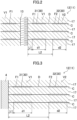
FIG. 2 is an enlarged cross-sectional view of a periphery of a fastener of a stator core. -
FIG. 3 is an enlarged cross-sectional view of a stator core in the vicinity of a casing according to a first variation. - An embodiment of the present disclosure will be described below with reference to the drawings. The embodiment below is merely exemplary one in nature, and is not intended to limit the scope, applications, or use of the present invention.
- An embodiment will be described.
FIG. 1 shows a compressor (1) according to a first embodiment. The compressor (1) is disposed, for example, in a refrigerant circuit (not shown) of an air conditioner. The compressor (1) compresses a refrigerant in the refrigerant circuit. As shown inFIG. 1 , the compressor (1) includes a motor (2), a compression mechanism (3), and a casing (4). - The casing (4) is a container that houses the compression mechanism (3) and the motor (2). The casing (4) is a holding member that holds a stator (10) of the motor (2).
- The casing (4) is a closed container. The casing (4) is made of metal, such as iron. The casing (4) is formed, for example, by forming a cylindrical member by so-called "roll bending" a sheet metal (e.g., a sheet of a material such as iron) and welding end plates (e.g., metal, such as iron) to both ends of the cylindrical member.
- The compression mechanism (3) compresses a fluid (a refrigerant in this example). The compression mechanism (3) may be any one of various fluid machines. For example, the compression mechanism (3) may be a rotary compression mechanism, a scroll compression mechanism, or any other suitable mechanism. In this example, the compression mechanism (3) takes a fluid in from an intake pipe (3a) provided in a side surface of the casing (4) and discharges the compressed fluid into the casing (4). The fluid (i.e., refrigerant) discharged into the casing (4) is discharged through a discharge pipe (3b).
- The motor (2) is an example of a rotating electrical machine. The motor (2) drives the compression mechanism (3). The motor (2) is a magnet embedded type rotating electrical machine. The motor (2) includes the stator (10), a rotor (20), and a shaft (2a).
- The shaft (2a) is a holding member that holds the rotor (20). The shaft (2a) is made of metal, such as iron. The shaft (2a) is connected to the compression mechanism (3) as well.
- In the following description, an axial direction corresponds to the direction in which the center of the shaft (2a) extends. A radial direction is orthogonal to the axial direction. A circumferential direction extends along a circle around the center of the shaft (2a).
- The rotor (20) includes a rotor core (21) and a permanent magnet (not shown). The permanent magnet is housed in a through hole in the rotor core (21).
- The rotor core (21) includes a laminated body (22). The laminated body (22) is a cylindrical member. The laminated body (22) is formed by stacking a large number of plate members (hereinafter referred to as "rotor plates (23)") in the axial direction. The rotor core (21) is a so-called laminated core.
- The rotor plates (23) are electrical steel sheets. The rotor plates (23) are manufactured by pressing electrical steel sheets, for example. The rotor plates (23) are coated with an insulating film. The rotor core (21) is manufactured by fixing the rotor plates (23) to each other through crimping, for example. Each rotor plate (23) has, at its center, a through hole for inserting the shaft (2a).
- The stator (10) includes the stator core (11) and a coil (16). The stator core (11) corresponds to the "core" according to the present disclosure. The stator core (11) includes a laminated body (12) and a fastener (13). The laminated body (12) is a cylindrical member. The laminated body (12) is formed by stacking a large number of plate members (hereinafter referred to as "stator plates (17)") in the axial direction. In other words, the stator plates (17) are stacked in a direction substantially parallel to the axial direction. The stator core (11) is a so-called "laminated core".
- The stator plates (17) are electrical steel sheets. The stator plate (17) are manufactured by pressing electrical steel sheets, for example. The stator plates (17) are coated with an insulating film. The stator core (11) is manufactured by fastening the stator plates (17) to each other with a bolt. In this example, the bolt serves as the fastener (13). The fastener (13) fastens a pair of adjacent electrical steel sheets. The stator plates (17) may be fastened to each other by crimping or welding.
- As shown in
FIG. 2 , the laminated body (12) has a plurality of contact areas (C). Each contact area (C) is interposed between a pair of adjacent stator plates (17, 17) of the laminated body (12). In other words, each contact area (C) is interposed between a pair of adjacent electrical steel sheets among the plurality of electrical steel sheets. - The contact areas (C) include direct contact areas (D) and a plurality of friction areas (F1, F2). In each direct contact area (D), a pair of adjacent stator plates (17, 17) are in direct contact with each other. The friction areas (F1, F2) have different friction coefficients from the direct contact areas (D). The plurality of friction areas (F1, F2) have friction coefficients different from each other. The "friction coefficients" used herein include coefficients of static friction and dynamic friction.
- The plurality of friction areas (F1, F2) includes a first friction area (F1) and a second friction area (F2). The respective friction coefficients of the friction areas (F1, F2) are measured in accordance with JIS K7125: 1999.
- The first friction area (F1) is located around the fastener (13). In this example, the first friction area (F1) surrounds the fastener (13) at a predetermined distance from the fastener (13).
- The second friction area (F2) is farther from the fastener (13) than the first friction area (F1) is. Here, assume that the shortest distance between the fastener (13) and the first friction area (F1) is a first distance L1, and the shortest distance between the fastener (13) and the second friction area (F2) is a second distance L2. The second distance L2 is longer than the first distance L1 (i.e., L1 < L2). In other words, the first friction area (F1) is closer to the fastener (13) than the second friction area (F2) is.
- Each first friction area is in a ring shape with a width (i.e., length in the radial direction) d1. Each second friction area (F2) is formed in a band shape with a width d2. In this example, the widths d1 of the first friction areas (F1) in the respective contact areas (C) are the same. The widths d2 of the respective second friction areas (F2) in the contact areas (C) are also the same. The plurality of first friction areas (F1) overlap each other in the stacking direction, and the plurality of second friction areas (F2) overlap each other in the stacking direction.
- One of each pair of stator plates (17, 17) is provided with a surface member (30) on its surface. In this example, the lower one of the pair of stator plates (17, 17) is provided with a first surface member (31) and a second surface member (32) on its surface. The first surface member (31) is made of rubber. The second surface member (32) is made of resin. The first friction area (F1) is interposed between the first surface member (31) and the stator plate (17). The second friction area (F2) is interposed between the second surface member (32) and the stator plate (17). The friction coefficient µ2 of the second friction area (F2) is smaller than the friction coefficient µ1 of the first friction area (F1) (i.e., µ1 > µ2).
- Once the motor is driven, an electromagnetic force acts on a gap (so-called "air gap") between the stator (10) and the rotor (20). This electromagnetic force excites the laminated body (12). The excitation of the laminated body (12) causes a pair of adjacent stator plates (17, 17) to oscillate. Each contact area (C) includes the plurality of friction areas (F1, F2) with different friction coefficients. Accordingly, when the pair of stator plates (17, 17) oscillate, the portions of the pair of stator plates (17, 17) forming the friction areas (F1, F2) move in different amounts in the shear direction.
- Specifically, the friction coefficient µ2 of the second friction area (F2) is smaller than the friction coefficient µ1 of the first friction area (F1) (i.e., µ1 > µ2). Accordingly, the stator plates (17) are less likely to move with respect to the first surface member (31) in the first friction area (F1) in the shear direction, and more likely to move with respect to the second surface member (32) in the second friction area (F2) in the shear direction.
- Oscillation of the laminated body (12) causes a pair of adjacent stator plates (17, 17) to oscillate in a predetermined amount of oscillation in the periphery of the fastener (13). Unlike the periphery of the fastener (13), the stator plates (17) are not fixed to each other in a portion away from the fastener (13) and hence oscillate in a greater amount of oscillation than in a first oscillating portion (V1).
- The periphery of the fastener (13), where the stator plates (17, 17) oscillate in a predetermined amount of oscillation, is regarded as the first oscillating portion (V1), and the portion that is away from the fastener (13) and oscillates in a greater amount of oscillation than in the first oscillating portion (V1) is regarded as a second oscillating portion (V2). The first friction area (F1) is formed in the first oscillating portion (V1), and the second friction area (F2) is formed in the second oscillating portion (V2).
- Since the second oscillating portion (V2) that oscillates in a greater amount of oscillation than the first oscillating portion (V1) has a smaller friction coefficient than the first oscillating portion (V1), the stator plates (17) can move in a greater amount with respect to the second surface member (32) in the second oscillating portion (V2). Accordingly, the oscillation energy at the second oscillating portion (V2) can be converted into the thermal energy caused by friction, which can further attenuate the oscillations of the pair of stator plates (17, 17).
- Feature (1) of this embodiment is that the contact area (C) includes a first friction area (F1) and a second friction area (F2) with friction coefficients different from each other.
- According to Feature (1) of this embodiment, the first and second friction areas (F1) and (F2) with different friction coefficients can be located at portions that oscillate in different amounts of oscillation when the pair of stator plates (17, 17) are excited, in order to provide an attenuation effect. It is therefore possible to reduce the oscillations of the stator core (11).
- Feature (2) of this embodiment is that the pair of stator plates (17, 17) include: a first oscillating portion (V1) that oscillates in a predetermined amount of oscillation when excited; and a second oscillating portion (V2) that oscillates in a greater amount of oscillation than the first oscillating portion (V1), that the first friction area (F1) is located in the first oscillating portion (V1), that the second friction area (F2) is located in the second oscillating portion (V2), and that the second friction area (F2) has a smaller friction coefficient than the first friction area (F1).
- According to Feature (2) of this embodiment, the second friction area (F2) with a smaller friction coefficient than the first friction area (F1) is located in the second oscillating portion (V2) that oscillates in a greater amount of oscillation than the first oscillating portion (V1). When the laminated body (12) oscillates, the amount of movement of the stator plates (17) is greater in the second oscillating portion (V2) than in the first oscillating portion (V1). Accordingly, the oscillation energy at the second oscillating portion (V2) can be converted into the thermal energy caused by friction, which further attenuates the oscillations of the pair of stator plates (17, 17).
- Feature (3) of this embodiment is that the first friction area (F1) is closer to the fastener (13) than the second friction area (F2) is.
- According to Feature (3) of this embodiment, the amount of oscillation of the pair of stator plates (17, 17) is smaller in a portion close to the fastener (13) than in a portion away from the fastener (13). The oscillations of the pair of the stator plates (17, 17) are further attenuated since the first friction area (F1) is closer to the fastener (13) than the second friction area (F2) is.
- Feature (4) of this embodiment is that at least one of the pair of stator plates (17, 17) is provided with a surface member (30) on a surface thereof, and at least one of the first friction area (F1) or the second friction area (F2) is located on the surface member (30).
- According to Feature (4) of this embodiment, at least one of the first friction area (F1) or the second friction area (F2) is located on the surface member (30). This configuration can attenuate the oscillations of the pair of stator plates (17, 17).
- As shown in
FIG. 3 , in the stator core (11) according to this embodiment, the first friction area (F1) may be located near the casing (4). - Specifically, the laminated body (12) of the stator core (11) is held by the casing (4). The first friction area (F1) extends in the circumferential direction along the casing (4) at a predetermined distance from the inner circumferential surface of the casing (4) in the radial direction. The second friction area (F2) is farther from the casing (4) than the first friction area (F1) is. The second friction area (F2) extends in the circumferential direction at a predetermined distance from the first friction area (F1) in the radial direction. The distance L2 between the second friction area (F2) and the casing (4) is longer than the distance L1 between the first friction area (F1) and the casing (4) (i.e., L1 < L2).
- In this example as well, oscillation of the laminated body (12) causes a pair of stator plates (17, 17) to oscillate in a predetermined amount of oscillation in the vicinity of the casing (4) holding the laminated body (12) (i.e., in the first oscillating portion (V1)). On the other hand, the stator plates (17) can move relative to each other in a portion away from the casing (4) (i.e., in the second oscillating portion (V2)) and thus oscillate in a greater amount of oscillation than in the first oscillating portion (V1).
- Since the second oscillating portion (V2) away from the casing (4) has a smaller friction coefficient than the first oscillating portion (V1) near the casing (4), the stator plates (17) can move in a greater amount with respect to the second surface member (32) in the second oscillating portion (V2). Accordingly, the oscillation energy at the second oscillating portion (V2) can be converted into the thermal energy caused by friction, which can further attenuate the oscillations of the pair of stator plates (17, 17).
- In the stator core (11) according to this embodiment, the surface member (30) may be an adhesive, varnish, a coating agent applied to the surfaces of the stator plates (17), or any other suitable substances. The configuration according to this variation, to, can attenuate the oscillations of the pair of stator plates (17, 17).
- In the stator core (11) according to this embodiment, the surface roughness may differ between the first and second friction areas (F1) and (F2) of a pair of stator plates (17, 17).
- Specifically, for example, at least one of the friction areas (F1, F2) may be produced by applying a surface finish to at least one of the pair of stator plates (17, 17) to change the roughness of the surface. In other words, instead of providing the surface member (30) on the stator plate (17), a surface finish may be applied to the stator plate (17) to change the surface roughness.
- In the case of applying a surface finish to change the surface roughness, at least one of the pair of stator plates (17, 17) may have fine asperities on a surface in the first friction area (F1) or the second friction area (F2). A surface of at least one of the pair of stator plates (17, 17) may be mirror finished.
- Here, the surface roughness is an arithmetic average roughness (Ra). The surface roughness is measured in this variation using a contact surface roughness tester. The second friction area (F2) has a smaller arithmetic average roughness than the first friction area (F1).
- In this variation as well, the surface roughness differs between the first friction area (F1) and the second friction area (F2), thereby making it possible for the first friction area (F1) and the second friction area (F2) to have different friction coefficients.
- The above-described embodiment may be modified as follows.
- In the stator core (11) according to the embodiment described above, the stator plates (17) may be fixed to each other by crimping. In this case, the crimped part serves as the fastener (13) of the present disclosure.
- In the stator core (11) according to the embodiment described above, the fastener (13) and the first friction area (F1) may be in contact with each other. In other words, the first distance L1, which is the shortest distance between the fastener (13) and the first friction area (F1), may be zero.
- In the stator core (11) according to the embodiment described above, the first friction area (F1) and the second friction area (F2) may be in contact with each other.
- In the stator core (11) according to the embodiment described above, the widths d1 of the first friction areas (F1) in the respective contact areas (C) are not necessarily the same. Similarly, the widths d2 of the respective second friction areas (F2) are not necessarily the same.
- In the stator core (11) according to the embodiment described above, some of the plurality of contact areas (C) may have a plurality of friction areas (F1, F2).
- The configuration of the contact areas (C) according to the embodiment described above may be applied to the rotor core (21). In this case, the shaft (2a) corresponds to the "holding member" according to the present disclosure.
- While a motor has been described as an example of a rotating electrical machine in the embodiment described above, the configuration of the contact areas (C) may be applied to a generator.
- The configuration of the contact areas (C) according to the embodiment described above may be applied to a stationary apparatus.
- While the embodiment and variations thereof have been described above, it will be understood that various changes in form and details may be made without departing from the spirit and scope of the claims. The embodiments, the variations, and the other embodiments may be combined and replaced with each other without deteriorating intended functions of the present disclosure.
- The ordinal numbers such as "first," "second," "third," ... , described above are used to distinguish the terms to which these expressions are given, and do not limit the number and order of the terms.
- As described above, the present disclosure is useful for a core, a rotating electrical machine, and a stationary apparatus.
-
- 1
- Compressor
- 2
- Motor (Rotating Electrical Machine)
- 2a
- Shaft (Holding Member)
- 4
- Casing (Holding Member)
- 11
- Stator Core (Core)
- 12
- Laminated Body
- 13
- Fastener
- 17
- Stator Plate
- 21
- Rotor Core (Core)
- 22
- Laminated Body
- 30
- Surface Member
- 31
- First Surface Member
- 32
- Second Surface Member
- C
- Contact Area
- F1
- First Friction Area
- F2
- Second Friction Area
- V1
- First Oscillating Portion
- V2
- Second Oscillating Portion
Claims (8)
- A core comprising:a laminated body (12, 22) including a plurality of electrical steel sheets stacked one on another;the laminated body (12, 22) including a contact area (C) between a pair of adjacent electrical steel sheets of the plurality of electrical steel sheets,the contact area (C) including a first friction area (F1) and a second friction area (F2) with friction coefficients different from each other.
- The core (11, 21) of claim 1, whereinthe pair of electrical steel sheets include: a first oscillating portion (V1) that oscillates in a predetermined amount of oscillation when excited; and a second oscillating portion (V2) that oscillates in a greater amount of oscillation than the first oscillating portion (V1),the first friction area (F1) is located in the first oscillating portion (V1),the second friction area (F2) is located in the second oscillating portion (V2), andthe second friction area (F2) has a smaller friction coefficient than the first friction area (F1).
- The core (11, 21) of claim 1 or 2, further comprising:a fastener (13) configured to fasten the pair of electrical steel sheets, whereinthe first friction area (F1) is closer to the fastener (13) than the second friction area (F2) is, andthe second friction area (F2) has a smaller friction coefficient than the first friction area (F 1).
- The core (11, 21) of any one of claims 1 to 3, whereinthe laminated body (12, 22) is held by a holding member (4, 2a),a distance between the second friction area (F2) and the holding member (4, 2a) is longer than a distance between the first friction area (F1) and the holding member (4, 2a), andthe second friction area (F2) has a smaller friction coefficient than the first friction area (F 1).
- The core (11, 21) of any one of claims 1 to 4, whereinat least one of the pair of electrical steel sheets is provided with a surface member (30) on a surface thereof, andat least one of the first friction area (F1) or the second friction area (F2) is located on the surface member (30).
- The core (11, 21) of any one of claims 1 to 5, wherein
the first friction area (F1) and the second friction area (F2) of the pair of electrical steel sheets differ from each other in surface roughness. - A rotating electrical machine comprising:
the core (11, 21) of any one of claims 1 to 6. - A stationary apparatus comprising:
the core (11, 21) of any one of claims 1 to 6.
Applications Claiming Priority (2)
| Application Number | Priority Date | Filing Date | Title |
|---|---|---|---|
| JP2020164403A JP7032675B1 (en) | 2020-09-30 | 2020-09-30 | Cores, rotating electromechanical machines, and resting machines |
| PCT/JP2021/035757 WO2022071359A1 (en) | 2020-09-30 | 2021-09-29 | Core, rotating electrical machine, and stationary apparatus |
Publications (2)
| Publication Number | Publication Date |
|---|---|
| EP4187561A1 true EP4187561A1 (en) | 2023-05-31 |
| EP4187561A4 EP4187561A4 (en) | 2024-08-21 |
Family
ID=80950595
Family Applications (1)
| Application Number | Title | Priority Date | Filing Date |
|---|---|---|---|
| EP21875659.1A Pending EP4187561A4 (en) | 2020-09-30 | 2021-09-29 | CORE, ROTATING ELECTRIC MACHINE AND FIXED APPARATUS |
Country Status (5)
| Country | Link |
|---|---|
| US (1) | US12401239B2 (en) |
| EP (1) | EP4187561A4 (en) |
| JP (1) | JP7032675B1 (en) |
| CN (1) | CN116210063B (en) |
| WO (1) | WO2022071359A1 (en) |
Families Citing this family (1)
| Publication number | Priority date | Publication date | Assignee | Title |
|---|---|---|---|---|
| JP7692016B2 (en) * | 2023-08-21 | 2025-06-12 | カバー株式会社 | Program, method, and system |
Family Cites Families (14)
| Publication number | Priority date | Publication date | Assignee | Title |
|---|---|---|---|---|
| US4085347A (en) * | 1976-01-16 | 1978-04-18 | White-Westinghouse Corporation | Laminated stator core |
| JP2000152570A (en) * | 1998-11-06 | 2000-05-30 | Toshiba Corp | Manufacturing method of magnet core |
| JP2006006081A (en) * | 2004-06-21 | 2006-01-05 | Asmo Co Ltd | Brushless motor and vehicular blower |
| ITMI20070508A1 (en) * | 2007-03-14 | 2008-09-15 | Corrada Spa | LAMINAR ARTICLE FOR ELECTRICAL USE PROCEDURE AND MACHINES TO REALIZE THE LAMINAR ARTICLE |
| JP5172367B2 (en) * | 2008-01-23 | 2013-03-27 | 三菱電機株式会社 | Laminated core, laminated core manufacturing method, laminated core manufacturing apparatus, and stator |
| JP2010110155A (en) * | 2008-10-31 | 2010-05-13 | Mazda Motor Corp | Rotating electrical machine and manufacturing method therefor |
| JP5691571B2 (en) * | 2011-01-31 | 2015-04-01 | Jfeスチール株式会社 | Motor core with low iron loss degradation under compressive stress and manufacturing method thereof |
| KR101923359B1 (en) * | 2015-11-25 | 2018-11-28 | 미쓰비시덴키 가부시키가이샤 | Manufacturing method of rotary electric and rotary electric |
| JP6681927B2 (en) * | 2018-02-07 | 2020-04-15 | 本田技研工業株式会社 | Stator core of rotating electric machine |
| JP7089162B2 (en) | 2018-03-30 | 2022-06-22 | ダイキン工業株式会社 | Rotating electric machines and compressors |
| CN108599481B (en) * | 2018-05-31 | 2020-10-30 | 广东威灵汽车部件有限公司 | Stator core manufacturing method, stator core, and motor |
| JP2020115709A (en) * | 2019-01-17 | 2020-07-30 | 本田技研工業株式会社 | Rotary electric machine |
| JP2020115710A (en) * | 2019-01-17 | 2020-07-30 | 本田技研工業株式会社 | Rotating electric machine |
| JP2020178411A (en) * | 2019-04-16 | 2020-10-29 | パナソニックIpマネジメント株式会社 | Stator core and motor |
-
2020
- 2020-09-30 JP JP2020164403A patent/JP7032675B1/en active Active
-
2021
- 2021-09-29 CN CN202180066032.XA patent/CN116210063B/en active Active
- 2021-09-29 EP EP21875659.1A patent/EP4187561A4/en active Pending
- 2021-09-29 WO PCT/JP2021/035757 patent/WO2022071359A1/en not_active Ceased
-
2023
- 2023-03-28 US US18/127,547 patent/US12401239B2/en active Active
Also Published As
| Publication number | Publication date |
|---|---|
| CN116210063A (en) | 2023-06-02 |
| US12401239B2 (en) | 2025-08-26 |
| US20230238841A1 (en) | 2023-07-27 |
| JP7032675B1 (en) | 2022-03-09 |
| CN116210063B (en) | 2026-05-01 |
| EP4187561A4 (en) | 2024-08-21 |
| JP2022056579A (en) | 2022-04-11 |
| WO2022071359A1 (en) | 2022-04-07 |
Similar Documents
| Publication | Publication Date | Title |
|---|---|---|
| KR102643516B1 (en) | Laminated core and rotating electric machines | |
| JP7362801B2 (en) | Electric motors, compressors, blowers, and refrigeration and air conditioning equipment | |
| CN102113196B (en) | Stator, motor and compressor | |
| EP3754814B1 (en) | Stator core and compressor | |
| EP1503476A1 (en) | Electric motor and compressor | |
| CN102111027A (en) | Permanent magnet type rotating electric machine | |
| US12401239B2 (en) | Core, rotating electrical machine, and stationary apparatus | |
| EP3101784A1 (en) | Electric pump | |
| EP4002648A1 (en) | Rotating electric machine, compressor, and method for manufacturing rotating electric machine | |
| CN103891106A (en) | Rotor for rotating electric machine and motor for electric power steering | |
| US20170284396A1 (en) | Electric compressor | |
| CN115250017B (en) | Stator | |
| JP5245435B2 (en) | motor | |
| US20170284395A1 (en) | Electric compressor | |
| CN103959605B (en) | The laminate core of motor | |
| CN111490661B (en) | Compressor provided with motor | |
| JPWO2019064376A1 (en) | Rotating electric machine | |
| US11218037B2 (en) | Stator and housing for rotating electrical machine | |
| US11183910B2 (en) | Squirrel cage induction motor for vehicle | |
| US20230318368A1 (en) | Motor, compressor, refrigeration cycle apparatus, and manufacturing method of motor | |
| US20250015645A1 (en) | Rotating electrical machine | |
| Rosli et al. | Modal analysis of an 8/6 pole switched reluctance motor core with different materials and assembly method using FEA | |
| CN115085420A (en) | Rotor and rotating electrical machine | |
| JP2022055556A (en) | motor | |
| WO2022071358A1 (en) | Core, rotary electric machine, and static device |
Legal Events
| Date | Code | Title | Description |
|---|---|---|---|
| STAA | Information on the status of an ep patent application or granted ep patent |
Free format text: STATUS: THE INTERNATIONAL PUBLICATION HAS BEEN MADE |
|
| PUAI | Public reference made under article 153(3) epc to a published international application that has entered the european phase |
Free format text: ORIGINAL CODE: 0009012 |
|
| STAA | Information on the status of an ep patent application or granted ep patent |
Free format text: STATUS: REQUEST FOR EXAMINATION WAS MADE |
|
| 17P | Request for examination filed |
Effective date: 20230222 |
|
| AK | Designated contracting states |
Kind code of ref document: A1 Designated state(s): AL AT BE BG CH CY CZ DE DK EE ES FI FR GB GR HR HU IE IS IT LI LT LU LV MC MK MT NL NO PL PT RO RS SE SI SK SM TR |
|
| DAV | Request for validation of the european patent (deleted) | ||
| DAX | Request for extension of the european patent (deleted) | ||
| P01 | Opt-out of the competence of the unified patent court (upc) registered |
Effective date: 20231201 |
|
| REG | Reference to a national code |
Ref country code: DE Ref legal event code: R079 Free format text: PREVIOUS MAIN CLASS: H01F0027245000 Ipc: H02K0001120000 |
|
| A4 | Supplementary search report drawn up and despatched |
Effective date: 20240718 |
|
| RIC1 | Information provided on ipc code assigned before grant |
Ipc: H02K 1/18 20060101ALN20240712BHEP Ipc: H01F 3/02 20060101ALI20240712BHEP Ipc: H02K 1/12 20060101AFI20240712BHEP |