EP4187520A1 - Message transmission system and method for roadside equipment - Google Patents
Message transmission system and method for roadside equipment Download PDFInfo
- Publication number
- EP4187520A1 EP4187520A1 EP21215994.1A EP21215994A EP4187520A1 EP 4187520 A1 EP4187520 A1 EP 4187520A1 EP 21215994 A EP21215994 A EP 21215994A EP 4187520 A1 EP4187520 A1 EP 4187520A1
- Authority
- EP
- European Patent Office
- Prior art keywords
- dangerous
- analysis
- intersection
- sign
- road
- Prior art date
- Legal status (The legal status is an assumption and is not a legal conclusion. Google has not performed a legal analysis and makes no representation as to the accuracy of the status listed.)
- Granted
Links
Images




Classifications
-
- G—PHYSICS
- G08—SIGNALLING
- G08G—TRAFFIC CONTROL SYSTEMS
- G08G1/00—Traffic control systems for road vehicles
- G08G1/01—Detecting movement of traffic to be counted or controlled
- G08G1/0104—Measuring and analyzing of parameters relative to traffic conditions
- G08G1/0125—Traffic data processing
- G08G1/0133—Traffic data processing for classifying traffic situation
-
- G—PHYSICS
- G08—SIGNALLING
- G08G—TRAFFIC CONTROL SYSTEMS
- G08G1/00—Traffic control systems for road vehicles
- G08G1/01—Detecting movement of traffic to be counted or controlled
- G08G1/0104—Measuring and analyzing of parameters relative to traffic conditions
- G08G1/0108—Measuring and analyzing of parameters relative to traffic conditions based on the source of data
- G08G1/0116—Measuring and analyzing of parameters relative to traffic conditions based on the source of data from roadside infrastructure, e.g. beacons
-
- G—PHYSICS
- G01—MEASURING; TESTING
- G01S—RADIO DIRECTION-FINDING; RADIO NAVIGATION; DETERMINING DISTANCE OR VELOCITY BY USE OF RADIO WAVES; LOCATING OR PRESENCE-DETECTING BY USE OF THE REFLECTION OR RERADIATION OF RADIO WAVES; ANALOGOUS ARRANGEMENTS USING OTHER WAVES
- G01S17/00—Systems using the reflection or reradiation of electromagnetic waves other than radio waves, e.g. lidar systems
- G01S17/88—Lidar systems specially adapted for specific applications
-
- G—PHYSICS
- G08—SIGNALLING
- G08G—TRAFFIC CONTROL SYSTEMS
- G08G1/00—Traffic control systems for road vehicles
- G08G1/01—Detecting movement of traffic to be counted or controlled
- G08G1/04—Detecting movement of traffic to be counted or controlled using optical or ultrasonic detectors
-
- G—PHYSICS
- G08—SIGNALLING
- G08G—TRAFFIC CONTROL SYSTEMS
- G08G1/00—Traffic control systems for road vehicles
- G08G1/01—Detecting movement of traffic to be counted or controlled
- G08G1/052—Detecting movement of traffic to be counted or controlled with provision for determining speed or overspeed
-
- G—PHYSICS
- G08—SIGNALLING
- G08G—TRAFFIC CONTROL SYSTEMS
- G08G1/00—Traffic control systems for road vehicles
- G08G1/07—Controlling traffic signals
- G08G1/081—Plural intersections under common control
-
- G—PHYSICS
- G08—SIGNALLING
- G08G—TRAFFIC CONTROL SYSTEMS
- G08G1/00—Traffic control systems for road vehicles
- G08G1/09—Arrangements for giving variable traffic instructions
- G08G1/091—Traffic information broadcasting
- G08G1/093—Data selection, e.g. prioritizing information, managing message queues, selecting the information to be output
-
- G—PHYSICS
- G08—SIGNALLING
- G08G—TRAFFIC CONTROL SYSTEMS
- G08G1/00—Traffic control systems for road vehicles
- G08G1/09—Arrangements for giving variable traffic instructions
- G08G1/0962—Arrangements for giving variable traffic instructions having an indicator mounted inside the vehicle, e.g. giving voice messages
- G08G1/0967—Systems involving transmission of highway information, e.g. weather, speed limits
- G08G1/096708—Systems involving transmission of highway information, e.g. weather, speed limits where the received information might be used to generate an automatic action on the vehicle control
-
- G—PHYSICS
- G08—SIGNALLING
- G08G—TRAFFIC CONTROL SYSTEMS
- G08G1/00—Traffic control systems for road vehicles
- G08G1/09—Arrangements for giving variable traffic instructions
- G08G1/0962—Arrangements for giving variable traffic instructions having an indicator mounted inside the vehicle, e.g. giving voice messages
- G08G1/0967—Systems involving transmission of highway information, e.g. weather, speed limits
- G08G1/096733—Systems involving transmission of highway information, e.g. weather, speed limits where a selection of the information might take place
- G08G1/096741—Systems involving transmission of highway information, e.g. weather, speed limits where a selection of the information might take place where the source of the transmitted information selects which information to transmit to each vehicle
-
- G—PHYSICS
- G08—SIGNALLING
- G08G—TRAFFIC CONTROL SYSTEMS
- G08G1/00—Traffic control systems for road vehicles
- G08G1/09—Arrangements for giving variable traffic instructions
- G08G1/0962—Arrangements for giving variable traffic instructions having an indicator mounted inside the vehicle, e.g. giving voice messages
- G08G1/0967—Systems involving transmission of highway information, e.g. weather, speed limits
- G08G1/096733—Systems involving transmission of highway information, e.g. weather, speed limits where a selection of the information might take place
- G08G1/096758—Systems involving transmission of highway information, e.g. weather, speed limits where a selection of the information might take place where no selection takes place on the transmitted or the received information
-
- G—PHYSICS
- G08—SIGNALLING
- G08G—TRAFFIC CONTROL SYSTEMS
- G08G1/00—Traffic control systems for road vehicles
- G08G1/09—Arrangements for giving variable traffic instructions
- G08G1/0962—Arrangements for giving variable traffic instructions having an indicator mounted inside the vehicle, e.g. giving voice messages
- G08G1/0967—Systems involving transmission of highway information, e.g. weather, speed limits
- G08G1/096766—Systems involving transmission of highway information, e.g. weather, speed limits where the system is characterised by the origin of the information transmission
- G08G1/096783—Systems involving transmission of highway information, e.g. weather, speed limits where the system is characterised by the origin of the information transmission where the origin of the information is a roadside individual element
-
- G—PHYSICS
- G08—SIGNALLING
- G08G—TRAFFIC CONTROL SYSTEMS
- G08G1/00—Traffic control systems for road vehicles
- G08G1/16—Anti-collision systems
- G08G1/164—Centralised systems, e.g. external to vehicles
-
- G—PHYSICS
- G08—SIGNALLING
- G08G—TRAFFIC CONTROL SYSTEMS
- G08G1/00—Traffic control systems for road vehicles
- G08G1/16—Anti-collision systems
- G08G1/166—Anti-collision systems for active traffic, e.g. moving vehicles, pedestrians, bikes
Definitions
- the disclosure relates in general to a roadside equipment, and more particularly to a message transmission system and a method thereof for a roadside equipment.
- RSU road side unit
- OBU on-board unit
- the disclosure is directed to a message transmission system and a method thereof for a roadside equipment, which can send out dangerous object messages based on a degree of danger of the object within the available transmission bandwidth, so as to reduce the transmission volume of vehicle-to-road communication.
- a message transmission method for roadside equipment includes the following steps: receiving information from a plurality of external sensors, entering a road intersection sign phase information and a road map information, performing an object position analysis, a speed analysis, and a sign analysis in object moving direction based on the external sensor information, the road intersection sign phase information, and the road map information, and outputting a classification of dangerous objects in different groups.
- a dangerous object message with a higher classification of the dangerous objects is preferentially selected and transmitted within an available transmission bandwidth.
- a message transmission system for a roadside equipment which includes a dynamic detection device for object at intersection, a sign receiving device, a dangerous object classification module, and a vehicle-to-road communication device.
- the dynamic detection device for object at intersection is used to receive information from a plurality of external sensors.
- the sign receiving device is used for inputting a road intersection sign phase information and a road map information.
- the dangerous object classification module performs an object position analysis, a speed analysis, and a sign analysis in object moving direction based on the external sensor information, the sign phase information of the road intersection, and the road map information, and outputs a classification of dangerous objects in different groups based on the external sensor information, the sign phase information of the road intersection, and the road map information.
- the vehicle-to-road communication device preferentially selects and transmits a dangerous object message with a higher classification of the dangerous objects within an available transmission bandwidth according to a current transmission bandwidth limitation and the classification of the dangerous objects.
- FIG. 1A is a schematic diagram of the operation of components of a message transmission system 100 for a roadside equipment according to an embodiment of the present disclosure
- FIG. 1B is a schematic diagram of a message transmission method for a roadside equipment according to an embodiment of the present disclosure.
- the message transmission system 100 for a roadside equipment includes a dynamic detection device 110 for object at the intersection, a sign receiving device 120, a dangerous object classification module 130, and a vehicle-to-road communication device 140.
- the dynamic detection device 110 at the intersection is installed on a side of the road to detect cars, motorcycles, bicycles, or pedestrians (hereinafter referred to as the object 101) passing through the intersection.
- the dynamic detection device 110 at the intersection can include LiDAR modules, laser ranging modules, camera modules, image recognition modules, and computing modules, etc., which can calculate the position, the speed, and the object moving direction of each detected object passing through the intersection in real time, the relative distance between the detected object and the intersection, and the relative distance between the object and the object.
- the dynamic detection device 110 at the intersection can cooperate one or more LiDAR modules, laser ranging modules or camera modules to obtain the external sensor information 112 corresponding to the object at the intersection, and obtain different types of external sensor information 112 through sensor fusion 113, which are aggregated into a cluster of object data 114 at the intersection for the machine to determine.
- the fused external sensor information 112 includes the position, the speed, the acceleration, the object moving direction and relative distance of the objects, etc.
- the fused external sensor information 112 can also include the type of objects (for example, truck, passenger car, bus, motorcycle), the state of the object (stationary, moving, straight moving, turning, decelerating, accelerating, etc.), determine whether the relative distance between the object and the intersection is greater than or less than a preset threshold, and whether the relative distance between the object and the object is greater than or less than a preset threshold, etc.
- objects for example, truck, passenger car, bus, motorcycle
- the state of the object stationary, moving, straight moving, turning, decelerating, accelerating, etc.
- the intersection 102 of a road can be an area surrounded by three or four road sections L1-L4, that is, the middle rectangular area defined by three or four road sections L1-L4 is the intersection 102, but the road sections are not limited to four, and it may be more than four sections.
- Each of the road sections L1-L4 is provided with a traffic sign 104 (traffic light or pass/turn indicator) to control the vehicles passing through the intersection 102, the pass direction of vehicles, and the pass time of vehicles.
- each intersection 102 has a traffic signal controller (not shown in the figure.). Through the network communication of the traffic signal controller, the traffic signal of each road section L1-L4 can be controlled in series, and the signs of each road section will not conflict to ensure the safety of vehicles passing through the intersection 102.
- the signal receiving device 120 may be connected to or wirelessly communicate with the traffic signal controller (not shown in the figure) of the intersection 102 to receive a sign phase information 122 at the intersection and a road map information 124.
- the sign phase information 122 includes signals, for example, red, yellow, green, left-turn green, right-turn green, and other signals.
- Road map information 124 includes, for example, the location of the intersection (e.g. the GPS coordinates of the center of the intersection), the type of intersection, the intersection area, the location of the sign, the position of the crossing lines, and the position of the stop line 106 of each road section, etc.
- the dynamic detection device 110 and the sign receiving device 120 can simultaneously input the external sensor information 112, the road map information 124, and the intersection sign phase information 122 corresponding to the intersection 102 for the message transmission system 100 to determine the objects near the intersection 102 in real time, the road map information 124, and the intersection sign phase information 122 etc., as shown in FIG. 2 .
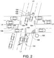
- FIG.2 is a schematic diagram of objects 101 at the intersection and their positions, speeds, and object moving directions according to an embodiment of the present disclosure.
- Each road section L1-L4 has two lanes in both directions, namely the lane leading to intersection 102 and the lane leaving intersection 102.
- Each lane has a plurality of objects 101 (that is, vehicles) driving on the road, each of the positions of the vehicles is detected, and the head of the vehicles is object moving direction.
- the italicized numbers next to the vehicles indicate the speed of each object.
- the speed will be adjusted dynamically according to the state of the vehicle.
- the speed of some vehicles that have left the intersection 102 is not displayed.
- the dangerous object classification module 130 can analyze the position, the speed, the object moving direction, and the signs in object moving direction of each detected object passing through the intersection 102 to output the classification of dangerous objects of different groups.
- FIG. 1B is a schematic diagram of a message transmission method for a roadside equipment according to an embodiment of the present disclosure.
- the message transmission method includes the following steps S110 to S140.
- step S110 a plurality of external sensor information 112 is received.
- step S120 an intersection sign phase information 122 and a road map information 124 are entered.
- step S130 an object position analysis 132, a speed analysis 134, and a sign analysis 136 in object moving direction are performed based on the external sensor information 112, the intersection sign phase message 122, and the road map information 124, and the classification of dangerous objects of different groups 139 is outputted.
- a dangerous object message 142 with a higher dangerous object classification is preferentially selected and transmitted within an available transmission bandwidth.
- the present disclosure can send a dangerous object message 142 based on the degree of danger of the objects within the available transmission bandwidth, so as to reduce the transmission volume of vehicle-to-road communication.
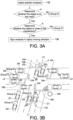
- FIG. 3A is a schematic diagram of the object position analysis 132 at the intersection according to an embodiment of the present disclosure
- FIG. 3B is a schematic diagram of objects at the intersection and the classification of dangerous objects in group D after the position analysis 132 of FIG. 3A
- FIG. 3C is a schematic diagram of the sign analysis 136 in object moving direction and speed analysis 134 of the objects at the intersection according to an embodiment of the present disclosure
- FIG. 3D is a schematic diagram of the classification of dangerous objects at the intersection in groups C and D after the sign analysis 136 and speed analysis 134 of FIG. 3C ;
- FIG. 3A is a schematic diagram of the object position analysis 132 at the intersection according to an embodiment of the present disclosure
- FIG. 3B is a schematic diagram of objects at the intersection and the classification of dangerous objects in group D after the position analysis 132 of FIG. 3A
- FIG. 3C is a schematic diagram of the sign analysis 136 in object moving direction and speed analysis 134 of the objects at the intersection according to an embodiment of the present disclosure
- FIG. 3E is a schematic diagram of the analysis 138 of the degree of danger of the objects at the intersection according to an embodiment of the present disclosure
- FIG. 3F is a schematic diagram of the classification of dangerous objects at the intersection in groups A, B, C, and D after the analysis 138 of the degree of danger of FIG. 3E .
- the object position analysis 132 includes (a) determining whether the object 101 is on the road, and if so, continues (b) determining whether the object 101 is close to the intersection. If it is determined that the object 101 is not on the road, for example, the vehicles D1 and D2 parked on the side of the road are not dangerous to other driving vehicles, so this type of object 101 is classified into a dangerous object of group D. In addition, if it is determined that the object 101 is far away from the intersection, for example, vehicles D3 to D6, it means that the vehicle has passed the intersection or far enough away from the intersection, and is not dangerous for other driving vehicles, so this type of object 101 is classified into a dangerous object of group D.
- the sign analysis 136 in the object moving direction and the speed analysis 134 are performed to determine whether this type of object 101 is classified into a dangerous object of group C. It is understandable that the danger degree of the dangerous object of group C is higher than that of the dangerous object of group D.
- the sign analysis 136 and speed analysis 134 of the object at the intersection include (a) determining whether the sign in object moving direction is a green light, if not, continue (b) determining whether the speed of the object is greater than a threshold.
- the sign in object moving direction is a green light
- the object 101 can be classified into a dangerous object of group C
- the sign in object moving direction is not green light and the speed of the object is less than the threshold
- the object 101 can be classified into a dangerous object of group C
- the sign in object moving direction is not green light and the speed of the object is greater than the threshold, continue to perform the analysis 138 of degree of danger of the object to determine whether the object 101 is classified into a dangerous object of group B.
- the vehicles on the north-south lane are classified into dangerous objects of group C except for the classification of dangerous objects of group D.
- the threshold for example, 10km/hr
- vehicles C2 and C3 it is not dangerous for the vehicles in the north-south lane, so this type of object 101 is classified into a dangerous object of group C.
- the speed of the vehicle in the east-west lane is greater than a threshold, for example, vehicle B1, it may be dangerous to the vehicle in the north-south lane.
- An analysis 138 of the degree of danger of the object is performed to determine whether this type of object 101 is classified into a dangerous object of group B. It is understandable that the danger degree of the dangerous object of group B is higher than that of the dangerous object of group C.
- the system 100 can perform an analysis 138 of the degree of danger based on the external sensor information 112, intersection sign phase information 122, and road map information 124.
- the analysis 138 of the degree of danger of the object at the intersection includes (a) determining whether the time from the object 101 to the intersection stop line 106 is greater than a threshold, if not, continues (b) determining whether the object 101 exceeds the stop line 106 .
- the object 101 can be classified into a dangerous object of group B; when the time from the object 101 to the stop line 106 of the intersection is less than the threshold and the object 101 does not exceed the stop line 106, the object 101 can be classified into a dangerous object of group B; when the time from the object 101 to the stop line 106 of the intersection is less than the threshold and the object 101 exceeds the stop line 106, the object 101 can be classified into a dangerous object of group A.
- the vehicle A1 When a vehicle in the east-west lane exceeds the stop line 106, for example, the vehicle A1, it may collide with a vehicle in the north-south lane (e.g., the vehicle A2) at a next time, and this type of object 101 can be classified into a dangerous objects of group A.
- the classification of the dangerous object of the vehicle A2 is increased to group A so as to have priority to send the dangerous object message 142 to the vehicles A1 and A2. It is understandable that the danger degree of the dangerous object of group A is higher than that of the dangerous object of group B, and the danger degree of the dangerous object of group B is higher than that of the dangerous object of group C.
- the vehicle-to-road communication device 140 preferentially selects and transmits a dangerous object message 142 with a higher dangerous object classification.
- the message of the dangerous object classification of group A is first transmitted, and then the message of the dangerous object classification of group B is transmitted, and then the messages of the dangerous object classification of group C and group D is finally transmitted.
- the vehicle-to-road communication device 140 sends a message to notify the object 101 at the intersection to ensure that the system 100 can instantly send a dangerous object message 142 within the available transmission bandwidth, reduce a chance of collision of objects 101 at the intersection and reduce the transmission volume of vehicle-to-road communication.
- the system 100 can scan the message of the surrounding vehicles at the intersection through radar and send the message through the roadside equipment with the function of dedicated short range communication (DSRC).
- the object messages at the intersection can be stored in the basic safety message (SAE J2735 BSM) and is broadcast regularly through exclusive short-range wireless communication.
- SAE J2735 BSM basic safety message
- OBU on-board unit
- the safety collision avoidance system judges the message with its own information by algorithm to determine whether a collision will occur to make an action to stop the vehicle automatically.
- V2X internet of vehicles
- the disclosure can be used in the vehicle-to-vehicle transmission, vehicle-to-road transmission and intersection sign transmission to strengthen driving safety, avoid collisions at intersection, and give priority to warn the drivers whose vehicles are about to collide (for example, vehicles A1 and A2) to pay attention to driving safety.
- the OBU can receive the road map information 124, sign phase information 122 at the intersection and the classification 139 of dangerous objects of the other vehicles from the system 100, but it is not limited, the driver can see whether there is a dangerous object message 142 (such as a sound or a picture) according to the in-vehicle user interface to help the driver brake early or reduce the speed of the car.
- a dangerous object message 142 such as a sound or a picture
- the disclosure can also be used in a left-turn anti-collision system to notify the driver of the dangerous object message 142 as soon as possible to prevent the driver's vision from being blocked by the oncoming vehicle waiting to turn left when the vehicle is turning left and causing a danger of collision with a straight-moving vehicle.
- the basic safety message (BSM) packets can are sent to other vehicles through the broadcast mechanism of this system 100, and the dangerous object messages 142 can be sent based on the limitation of the current transmission bandwidth and the degree of danger from high to low to reduce a chance of object collisions and reduce the transmission volume of vehicle-to-road communication to meet market demand.
- BSM basic safety message
Landscapes
- Physics & Mathematics (AREA)
- General Physics & Mathematics (AREA)
- Life Sciences & Earth Sciences (AREA)
- Atmospheric Sciences (AREA)
- Engineering & Computer Science (AREA)
- Analytical Chemistry (AREA)
- Chemical & Material Sciences (AREA)
- Remote Sensing (AREA)
- Radar, Positioning & Navigation (AREA)
- Electromagnetism (AREA)
- Computer Networks & Wireless Communication (AREA)
- Multimedia (AREA)
- Traffic Control Systems (AREA)
- Mobile Radio Communication Systems (AREA)
Abstract

Description
- The disclosure relates in general to a roadside equipment, and more particularly to a message transmission system and a method thereof for a roadside equipment.
- The current broadcast operation method of a road side unit (RSU) is limited by bandwidth. If there are too many object messages, the distance between the object and the intersection can only be used as a basis for selection of messages. In addition, if all object messages are sent by broadcast, RSU cannot accurately provide dangerous object messages, because some object messages (such as vehicles stopped on the roadside, vehicles far away from intersection) are not related to those objects with on-board unit (OBU), and it will result in a waste of resources of wireless transmission bandwidth.
- The disclosure is directed to a message transmission system and a method thereof for a roadside equipment, which can send out dangerous object messages based on a degree of danger of the object within the available transmission bandwidth, so as to reduce the transmission volume of vehicle-to-road communication.
- According to one embodiment, a message transmission method for roadside equipment is provided and includes the following steps: receiving information from a plurality of external sensors, entering a road intersection sign phase information and a road map information, performing an object position analysis, a speed analysis, and a sign analysis in object moving direction based on the external sensor information, the road intersection sign phase information, and the road map information, and outputting a classification of dangerous objects in different groups. According to a current transmission bandwidth limitation and the classification of the dangerous objects, a dangerous object message with a higher classification of the dangerous objects is preferentially selected and transmitted within an available transmission bandwidth.
- According to another embodiment, a message transmission system for a roadside equipment is provided, which includes a dynamic detection device for object at intersection, a sign receiving device, a dangerous object classification module, and a vehicle-to-road communication device. The dynamic detection device for object at intersection is used to receive information from a plurality of external sensors. The sign receiving device is used for inputting a road intersection sign phase information and a road map information. The dangerous object classification module performs an object position analysis, a speed analysis, and a sign analysis in object moving direction based on the external sensor information, the sign phase information of the road intersection, and the road map information, and outputs a classification of dangerous objects in different groups based on the external sensor information, the sign phase information of the road intersection, and the road map information. The vehicle-to-road communication device preferentially selects and transmits a dangerous object message with a higher classification of the dangerous objects within an available transmission bandwidth according to a current transmission bandwidth limitation and the classification of the dangerous objects.
- The above and other aspects of the disclosure will become better understood with regard to the following detailed description of the embodiment(s). The following description is made with reference to the accompanying drawings.
-
-
FIG. 1A is a schematic diagram showing the operation of components of a message transmission system for a roadside equipment according to an embodiment of the present disclosure; -
FIG. 1B is a schematic diagram of a method of transmitting message for a roadside equipment according to an embodiment of the present disclosure; -
FIG. 2 is a schematic diagram of an object at an intersection and its position, speed, and moving direction according to an embodiment of the present disclosure; -
FIG. 3A is a schematic diagram of the position analysis of object at the intersection according to an embodiment of the present disclosure; -
FIG. 3B is a schematic diagram of objects at the intersection and the classification of dangerous objects in group D after the position analysis ofFIG. 3A ; -
FIG. 3C is a schematic diagram of the sign analysis in object moving direction and speed analysis of the objects at the intersection according to an embodiment of the present disclosure; -
FIG. 3D is a schematic diagram of the classification of dangerous objects at the intersection in groups C and D after the sign analysis and speed analysis ofFIG. 3C ; -
FIG. 3E is a schematic diagram of the analysis of the degree of danger of the objects at the intersection according to an embodiment of the present disclosure; -
FIG. 3F is a schematic diagram of the classification of dangerous objects at the intersection in groups A, B, C, and D after the analysis of the degree of danger ofFIG. 3E . - In the following detailed description, for purposes of explanation, numerous specific details are set forth in order to provide a thorough understanding of the disclosed embodiments. It will be apparent, however, that one or more embodiments may be practiced without these specific details. In other instances, well-known structures and devices are schematically shown in order to simplify the drawing.
- Technical solutions for the embodiments of the present application are clearly and thoroughly disclosed with accompanying drawings. Obviously, the embodiments disclosed below are only some rather than all of the embodiments of the present disclosure. All embodiments obtained by anyone ordinarily skilled in the art of the present application according to the disclosed embodiments of the present disclosure are within the scope of protection of the present disclosure if the obtained embodiments are obvious. The same or similar elements will be represented by the same or similar reference signs.
- Please refer to
FIGS. 1A and1B .FIG. 1A is a schematic diagram of the operation of components of amessage transmission system 100 for a roadside equipment according to an embodiment of the present disclosure, andFIG. 1B is a schematic diagram of a message transmission method for a roadside equipment according to an embodiment of the present disclosure. - In this embodiment, the
message transmission system 100 for a roadside equipment includes adynamic detection device 110 for object at the intersection, asign receiving device 120, a dangerousobject classification module 130, and a vehicle-to-road communication device 140. Thedynamic detection device 110 at the intersection is installed on a side of the road to detect cars, motorcycles, bicycles, or pedestrians (hereinafter referred to as the object 101) passing through the intersection. Thedynamic detection device 110 at the intersection can include LiDAR modules, laser ranging modules, camera modules, image recognition modules, and computing modules, etc., which can calculate the position, the speed, and the object moving direction of each detected object passing through the intersection in real time, the relative distance between the detected object and the intersection, and the relative distance between the object and the object. - In this embodiment, the
dynamic detection device 110 at the intersection can cooperate one or more LiDAR modules, laser ranging modules or camera modules to obtain theexternal sensor information 112 corresponding to the object at the intersection, and obtain different types ofexternal sensor information 112 throughsensor fusion 113, which are aggregated into a cluster ofobject data 114 at the intersection for the machine to determine. The fusedexternal sensor information 112 includes the position, the speed, the acceleration, the object moving direction and relative distance of the objects, etc. In addition, the fusedexternal sensor information 112 can also include the type of objects (for example, truck, passenger car, bus, motorcycle), the state of the object (stationary, moving, straight moving, turning, decelerating, accelerating, etc.), determine whether the relative distance between the object and the intersection is greater than or less than a preset threshold, and whether the relative distance between the object and the object is greater than or less than a preset threshold, etc. - Please refer to
FIG. 2 . Generally, theintersection 102 of a road can be an area surrounded by three or four road sections L1-L4, that is, the middle rectangular area defined by three or four road sections L1-L4 is theintersection 102, but the road sections are not limited to four, and it may be more than four sections. Each of the road sections L1-L4 is provided with a traffic sign 104 (traffic light or pass/turn indicator) to control the vehicles passing through theintersection 102, the pass direction of vehicles, and the pass time of vehicles. In addition, eachintersection 102 has a traffic signal controller (not shown in the figure.). Through the network communication of the traffic signal controller, the traffic signal of each road section L1-L4 can be controlled in series, and the signs of each road section will not conflict to ensure the safety of vehicles passing through theintersection 102. - In this embodiment, the
signal receiving device 120 may be connected to or wirelessly communicate with the traffic signal controller (not shown in the figure) of theintersection 102 to receive asign phase information 122 at the intersection and aroad map information 124. Thesign phase information 122 includes signals, for example, red, yellow, green, left-turn green, right-turn green, and other signals.Road map information 124 includes, for example, the location of the intersection (e.g. the GPS coordinates of the center of the intersection), the type of intersection, the intersection area, the location of the sign, the position of the crossing lines, and the position of thestop line 106 of each road section, etc. - In this embodiment, the
dynamic detection device 110 and thesign receiving device 120 can simultaneously input theexternal sensor information 112, theroad map information 124, and the intersectionsign phase information 122 corresponding to theintersection 102 for themessage transmission system 100 to determine the objects near theintersection 102 in real time, theroad map information 124, and the intersectionsign phase information 122 etc., as shown inFIG. 2 . - Please refer to
FIG. 2. FIG.2 is a schematic diagram ofobjects 101 at the intersection and their positions, speeds, and object moving directions according to an embodiment of the present disclosure. Each road section L1-L4 has two lanes in both directions, namely the lane leading tointersection 102 and thelane leaving intersection 102. There are a total of eight lanes. Each lane has a plurality of objects 101 (that is, vehicles) driving on the road, each of the positions of the vehicles is detected, and the head of the vehicles is object moving direction. The italicized numbers next to the vehicles indicate the speed of each object. The speed will be adjusted dynamically according to the state of the vehicle. The speed of some vehicles that have left theintersection 102 is not displayed. The following is only an example showing the speed of vehicles approaching theintersection 102 as a basis for classification. In this embodiment, the dangerousobject classification module 130 can analyze the position, the speed, the object moving direction, and the signs in object moving direction of each detected object passing through theintersection 102 to output the classification of dangerous objects of different groups. - Please refer to
FIGS. 1A ,1B , and2 .FIG. 1B is a schematic diagram of a message transmission method for a roadside equipment according to an embodiment of the present disclosure. The message transmission method includes the following steps S110 to S140. In step S110, a plurality ofexternal sensor information 112 is received. In step S120, an intersectionsign phase information 122 and aroad map information 124 are entered. In step S130, anobject position analysis 132, aspeed analysis 134, and asign analysis 136 in object moving direction are performed based on theexternal sensor information 112, the intersectionsign phase message 122, and theroad map information 124, and the classification of dangerous objects ofdifferent groups 139 is outputted. In step S140, adangerous object message 142 with a higher dangerous object classification is preferentially selected and transmitted within an available transmission bandwidth. In such way, the present disclosure can send adangerous object message 142 based on the degree of danger of the objects within the available transmission bandwidth, so as to reduce the transmission volume of vehicle-to-road communication. - A specific example of the classification of
dangerous objects 139 has been shown inFIGS. 3A to 3F .FIG. 3A is a schematic diagram of theobject position analysis 132 at the intersection according to an embodiment of the present disclosure;FIG. 3B is a schematic diagram of objects at the intersection and the classification of dangerous objects in group D after theposition analysis 132 ofFIG. 3A ;FIG. 3C is a schematic diagram of thesign analysis 136 in object moving direction andspeed analysis 134 of the objects at the intersection according to an embodiment of the present disclosure;FIG. 3D is a schematic diagram of the classification of dangerous objects at the intersection in groups C and D after thesign analysis 136 andspeed analysis 134 ofFIG. 3C ;FIG. 3E is a schematic diagram of theanalysis 138 of the degree of danger of the objects at the intersection according to an embodiment of the present disclosure;FIG. 3F is a schematic diagram of the classification of dangerous objects at the intersection in groups A, B, C, and D after theanalysis 138 of the degree of danger ofFIG. 3E . - First, in
FIGS. 3A and 3B , theobject position analysis 132 includes (a) determining whether theobject 101 is on the road, and if so, continues (b) determining whether theobject 101 is close to the intersection. If it is determined that theobject 101 is not on the road, for example, the vehicles D1 and D2 parked on the side of the road are not dangerous to other driving vehicles, so this type ofobject 101 is classified into a dangerous object of group D. In addition, if it is determined that theobject 101 is far away from the intersection, for example, vehicles D3 to D6, it means that the vehicle has passed the intersection or far enough away from the intersection, and is not dangerous for other driving vehicles, so this type ofobject 101 is classified into a dangerous object of group D. In addition, if it is determined that theobject 101 is on the road and is close to theintersection 102, for example, the vehicle C1, thesign analysis 136 in the object moving direction and thespeed analysis 134 are performed to determine whether this type ofobject 101 is classified into a dangerous object of group C. It is understandable that the danger degree of the dangerous object of group C is higher than that of the dangerous object of group D. - Further, in
FIGS. 3C and3D , thesign analysis 136 andspeed analysis 134 of the object at the intersection include (a) determining whether the sign in object moving direction is a green light, if not, continue (b) determining whether the speed of the object is greater than a threshold. When the sign in object moving direction is a green light, theobject 101 can be classified into a dangerous object of group C; when the sign in object moving direction is not green light and the speed of the object is less than the threshold, theobject 101 can be classified into a dangerous object of group C; when the sign in object moving direction is not green light and the speed of the object is greater than the threshold, continue to perform theanalysis 138 of degree of danger of the object to determine whether theobject 101 is classified into a dangerous object of group B. - For example, in
FIG. 3D , when the north-south lane is green light and the east-west lane is red light, the vehicles on the north-south lane are classified into dangerous objects of group C except for the classification of dangerous objects of group D. Then, when the speed of the vehicle in the east-west lane is less than the threshold (for example, 10km/hr), for example, vehicles C2 and C3, it is not dangerous for the vehicles in the north-south lane, so this type ofobject 101 is classified into a dangerous object of group C. When the speed of the vehicle in the east-west lane is greater than a threshold, for example, vehicle B1, it may be dangerous to the vehicle in the north-south lane. Ananalysis 138 of the degree of danger of the object is performed to determine whether this type ofobject 101 is classified into a dangerous object of group B. It is understandable that the danger degree of the dangerous object of group B is higher than that of the dangerous object of group C. - Further, in addition to the above-mentioned
object position analysis 132,speed analysis 134, and signanalysis 136 in object moving direction, thesystem 100 can perform ananalysis 138 of the degree of danger based on theexternal sensor information 112, intersectionsign phase information 122, androad map information 124. InFIGS. 3E and3F , theanalysis 138 of the degree of danger of the object at the intersection includes (a) determining whether the time from theobject 101 to theintersection stop line 106 is greater than a threshold, if not, continues (b) determining whether theobject 101 exceeds thestop line 106 . When the time from theobject 101 to thestop line 106 of the intersection is greater than the threshold, theobject 101 can be classified into a dangerous object of group B; when the time from theobject 101 to thestop line 106 of the intersection is less than the threshold and theobject 101 does not exceed thestop line 106, theobject 101 can be classified into a dangerous object of group B; when the time from theobject 101 to thestop line 106 of the intersection is less than the threshold and theobject 101 exceeds thestop line 106, theobject 101 can be classified into a dangerous object of group A. - For example, in
FIG. 3F , when the east-west lane is red light, and the time from a vehicle on the east-west lane to thestop line 106 of the intersection is greater than a threshold, for example, the vehicle B1, it indicates that the vehicle is away from thestop line 106 about a certain distance, and it is still possible to stop without exceeding the stop line and is not dangerous for vehicles on the north-south lane. Therefore, this type ofobject 101 can be classified into a dangerous object of group B. When a vehicle in the east-west lane exceeds thestop line 106, for example, the vehicle A1, it may collide with a vehicle in the north-south lane (e.g., the vehicle A2) at a next time, and this type ofobject 101 can be classified into a dangerous objects of group A. In this embodiment, when anobject 101 with a high degree of danger (e.g., the vehicle A1) appears in the moving direction of the vehicle A2, the classification of the dangerous object of the vehicle A2 is increased to group A so as to have priority to send thedangerous object message 142 to the vehicles A1 and A2. It is understandable that the danger degree of the dangerous object of group A is higher than that of the dangerous object of group B, and the danger degree of the dangerous object of group B is higher than that of the dangerous object of group C. - In this embodiment, the vehicle-to-
road communication device 140 preferentially selects and transmits adangerous object message 142 with a higher dangerous object classification. In other words, the message of the dangerous object classification of group A is first transmitted, and then the message of the dangerous object classification of group B is transmitted, and then the messages of the dangerous object classification of group C and group D is finally transmitted. According to the limitation of the current transmission bandwidth and the classification of the degree of danger from high to low, the vehicle-to-road communication device 140 sends a message to notify theobject 101 at the intersection to ensure that thesystem 100 can instantly send adangerous object message 142 within the available transmission bandwidth, reduce a chance of collision ofobjects 101 at the intersection and reduce the transmission volume of vehicle-to-road communication. - The
system 100 can scan the message of the surrounding vehicles at the intersection through radar and send the message through the roadside equipment with the function of dedicated short range communication (DSRC). The object messages at the intersection can be stored in the basic safety message (SAE J2735 BSM) and is broadcast regularly through exclusive short-range wireless communication. When the on-board unit (OBU) of auto-driving car receives this message and parses it, the safety collision avoidance system judges the message with its own information by algorithm to determine whether a collision will occur to make an action to stop the vehicle automatically. - For example, the internet of vehicles (V2X) technology is used on a road to improve the safety of auto-driving cars, and the primary task is how to make vehicles have safety protection during driving and reduce the incidence of traffic accidents. The disclosure can be used in the vehicle-to-vehicle transmission, vehicle-to-road transmission and intersection sign transmission to strengthen driving safety, avoid collisions at intersection, and give priority to warn the drivers whose vehicles are about to collide (for example, vehicles A1 and A2) to pay attention to driving safety. Therefore, when a vehicle equipped with on-board unit (OBU) approaches the roadside equipment and is about to pass through the
intersection 102, the OBU can receive theroad map information 124, signphase information 122 at the intersection and theclassification 139 of dangerous objects of the other vehicles from thesystem 100, but it is not limited, the driver can see whether there is a dangerous object message 142 (such as a sound or a picture) according to the in-vehicle user interface to help the driver brake early or reduce the speed of the car. In addition, the disclosure can also be used in a left-turn anti-collision system to notify the driver of thedangerous object message 142 as soon as possible to prevent the driver's vision from being blocked by the oncoming vehicle waiting to turn left when the vehicle is turning left and causing a danger of collision with a straight-moving vehicle. - Especially for objects without BSM capabilities (such as pedestrians, motorcycles, or cars without OBU), the basic safety message (BSM) packets can are sent to other vehicles through the broadcast mechanism of this
system 100, and thedangerous object messages 142 can be sent based on the limitation of the current transmission bandwidth and the degree of danger from high to low to reduce a chance of object collisions and reduce the transmission volume of vehicle-to-road communication to meet market demand. - It will be apparent to those skilled in the art that various modifications and variations can be made to the disclosed embodiments. It is intended that the specification and examples be considered as exemplary only, with a true scope of the disclosure being indicated by the following claims and their equivalents.
Claims (12)
- A message transmission method for a roadside equipment, wherein the message transmission method comprises:receiving information from a plurality of external sensors (112);entering a road intersection sign phase information (122) and a road map information (124);performing an object position analysis (132), a speed analysis (134), and a sign analysis in object moving direction (136) based on the external sensor information (112), the road intersection sign phase information (122), and the road map information (124);outputting a classification of dangerous objects in different groups (139) according to the object position analysis (132), the speed analysis (134), and the sign analysis in object moving direction (136); andaccording to a current transmission bandwidth limitation and the classification of the dangerous objects, a dangerous object message (142) with a higher classification of the dangerous objects is preferentially selected and transmitted within an available transmission bandwidth.
- The method according to claim 1, wherein the external sensor information comprises radar information, LiDAR information, or camera information at the intersection.
- The method according to claim 1 or 2, wherein after receiving the external sensor information (112), the method further includes performing sensor fusion (113) on the external sensor information.
- The method according to anyone of the claims 1 to 3, wherein the object position analysis (132) comprises:determine whether an object (101) is on a road; anddetermine whether the object is close to the intersection,when the object is not on the road, the object is classified into a dangerous object of group D;when the object is on the road and the object is far away from the intersection, the object is classified into a dangerous object of group D;when the object is on the road and the object is close to the intersection, the sign analysis in object moving direction (136) and the speed analysis (134) are performed.
- The method according to anyone of the claims 1 to 4, wherein the sign analysis in the object moving direction (136) and the speed analysis (134) comprise:determining whether a sign in object moving direction of an object is a green light; anddetermining whether a speed of the object is greater than a threshold,when the sign in the object moving direction is a green light, the object is classified into a dangerous object of group C;when the sign in the object moving direction is not a green light and the speed of the object is less than the threshold, the object is classified into a dangerous object of group C;when the sign in the object moving direction is not a green light and the speed of the object is greater than the threshold, an analysis of degree of danger (138) is performed.
- The method according to claim 5, wherein the analysis of degree of danger (138) comprises:determine whether a time from an object to a stop line of the intersection is greater than a threshold; anddetermine whether the object exceeds the stop line,when the time from the object to the stop line is greater than the threshold, the object is classified into a dangerous object of group B;when the time from the object to the stop line is less than the threshold and the object does not exceed the stop line, the object is classified into the dangerous object of group B;when the time from the object to the stop line is less than the threshold and the object exceeds the stop line, the object is classified into a dangerous object of group A.
- A message transmission system for a roadside equipment (100), wherein the message transmission system comprises:a dynamic detection device for object at intersection (110) used to receive information from a plurality of external sensors;a signal receiving device (120) for inputting a sign phase information and a road map information;a dangerous object grading module (130) for performing an object position analysis (132), a speed analysis (134), and a sign analysis in object moving direction (136) based on the external sensor information (112), the road intersection sign phase information (122), and the road map information (124) and outputting a classification of dangerous objects in different groups (139) according to the object position analysis (132), the speed analysis (134), and the sign analysis in object moving direction (136);a vehicle-to-road communication device (140) for preferentially selecting and transmitting a dangerous object message (142) with a higher classification of the dangerous objects within an available transmission bandwidth according to a current transmission bandwidth limitation and the classification of the dangerous objects.
- The system according to claim 7, wherein the external sensor information (112) comprises radar information, LiDAR information, or camera information at the intersection.
- The system according to claim 7 or 8, wherein after the dynamic detection device (110) receives the external sensor information, the system further includes performing sensor fusion (113) on the external sensor information.
- The system according to anyone of the claims 7 to 9, wherein the object position analysis (132) comprises:determine whether an object (101) is on a road; anddetermine whether the object is close to the intersection,when the object is not on the road, the object is classified into a dangerous object of group D;when the object is on the road and the object is far away from the intersection, the object is classified into a dangerous object of group D;when the object is on the road and the object is close to the intersection, the sign analysis in object moving direction (136) and the speed analysis (134) are performed.
- The system according to anyone of the claims 7 to 10, wherein the sign analysis in the object moving direction (136) and the speed analysis (134) comprise:determining whether a sign in object moving direction of an object is a green light; anddetermining whether a speed of the object is greater than a threshold,when the sign in the object moving direction is a green light, the object is classified into a dangerous object of group C;when the sign in the object moving direction is not a green light and the speed of the object is less than the threshold, the object is classified into a dangerous object of group C;when the sign in the object moving direction is not a green light and the speed of the object is greater than the threshold, an analysis of degree of danger (138) is performed.
- The system according to claim 11, wherein the analysis of degree of danger (138) comprises:determine whether a time from an object to a stop line of the intersection is greater than a threshold; anddetermine whether the object exceeds the stop line,when the time from the object to the stop line is greater than the threshold, the object is classified into a dangerous object of group B;when the time from the object to the stop line is less than the threshold and the object does not exceed the stop line, the object is classified into the dangerous object of group B;when the time from the object to the stop line is less than the threshold and the object exceeds the stop line, the object is classified into a dangerous object of group A.
Applications Claiming Priority (1)
| Application Number | Priority Date | Filing Date | Title |
|---|---|---|---|
| TW110143862A TWI797847B (en) | 2021-11-24 | 2021-11-24 | Message transmission system and method for roadside equipment |
Publications (2)
| Publication Number | Publication Date |
|---|---|
| EP4187520A1 true EP4187520A1 (en) | 2023-05-31 |
| EP4187520B1 EP4187520B1 (en) | 2025-01-29 |
Family
ID=78957571
Family Applications (1)
| Application Number | Title | Priority Date | Filing Date |
|---|---|---|---|
| EP21215994.1A Active EP4187520B1 (en) | 2021-11-24 | 2021-12-20 | Message transmission system and method for roadside equipment |
Country Status (3)
| Country | Link |
|---|---|
| US (1) | US12198540B2 (en) |
| EP (1) | EP4187520B1 (en) |
| TW (1) | TWI797847B (en) |
Citations (3)
| Publication number | Priority date | Publication date | Assignee | Title |
|---|---|---|---|---|
| US20130279491A1 (en) * | 2012-04-24 | 2013-10-24 | Zetta Research And Development Llc - Forc Series | Hybrid protocol transceiver for v2v communication |
| US20210046941A1 (en) * | 2018-09-24 | 2021-02-18 | C.R.F. Societa' Consortile Per Azioni | Automotive driver assistance |
| US20210183244A1 (en) * | 2019-12-17 | 2021-06-17 | Denso International America, Inc. | Intersection infrastructure warning system |
Family Cites Families (36)
| Publication number | Priority date | Publication date | Assignee | Title |
|---|---|---|---|---|
| US6321158B1 (en) * | 1994-06-24 | 2001-11-20 | Delorme Publishing Company | Integrated routing/mapping information |
| JP3485239B2 (en) * | 1997-09-10 | 2004-01-13 | 富士重工業株式会社 | Vehicle motion control device |
| DE19959597C1 (en) * | 1999-12-10 | 2001-02-15 | Bayerische Motoren Werke Ag | Method and device for optical display of pieces of interconnected or interrelated information in motor vehicles uses an electronically controllable display panel. |
| JP2002329291A (en) * | 2001-04-27 | 2002-11-15 | Mitsubishi Heavy Ind Ltd | Device and system for intersection information |
| JP4578795B2 (en) * | 2003-03-26 | 2010-11-10 | 富士通テン株式会社 | Vehicle control device, vehicle control method, and vehicle control program |
| US20070129012A1 (en) * | 2003-04-01 | 2007-06-07 | Iceberg Systems Limited | Portable digital devices |
| JP4737519B2 (en) * | 2005-06-28 | 2011-08-03 | アイシン・エィ・ダブリュ株式会社 | Vehicle control auxiliary device and vehicle control auxiliary method |
| JP4672061B2 (en) * | 2006-10-03 | 2011-04-20 | 三菱電機株式会社 | Hybrid vehicle |
| GB0713336D0 (en) * | 2007-07-10 | 2007-08-22 | Hw Comm Ltd | Occupancy declaration/verification for passenger transport conveyances |
| US9493171B2 (en) * | 2008-10-30 | 2016-11-15 | Ford Global Technologies, Llc | Vehicle and method of advising a driver therein |
| JP2010183687A (en) * | 2009-02-04 | 2010-08-19 | Hitachi Constr Mach Co Ltd | Device and method for driving support of motor-driven truck |
| US8384532B2 (en) * | 2009-04-02 | 2013-02-26 | GM Global Technology Operations LLC | Lane of travel on windshield head-up display |
| JP5518257B2 (en) * | 2011-04-21 | 2014-06-11 | 三菱電機株式会社 | Driving support device |
| TWI508032B (en) | 2012-05-25 | 2015-11-11 | Nat Univ Tsing Hua | Control method of traffic sign by utilizing vehicular network |
| US20140232518A1 (en) * | 2013-02-15 | 2014-08-21 | Cah Technology | Systems and methods for an automated parking facility |
| CN103437255B (en) * | 2013-08-30 | 2015-09-02 | 武汉理工大学 | A kind of mountain area arterial highway " T "-intersection Design of Traffic Safety method |
| JP6385710B2 (en) * | 2014-04-21 | 2018-09-05 | 日本信号株式会社 | Signal control system |
| CN105280005A (en) | 2014-06-06 | 2016-01-27 | 电信科学技术研究院 | Road safety message sending method and device |
| TWI662519B (en) * | 2016-09-26 | 2019-06-11 | 財團法人工業技術研究院 | Roadside display system, roadside unit and roadside display method thereof |
| US9929165B1 (en) | 2016-09-28 | 2018-03-27 | Globalfoundries Singapore Pte. Ltd. | Method for producing integrated circuit memory cells with less dedicated lithographic steps |
| US9896106B1 (en) * | 2016-10-24 | 2018-02-20 | Toyota Motor Engineering & Manufacturing North America, Inc. | Coasting distance determination for coasting assistance system |
| CN107067816A (en) * | 2017-04-07 | 2017-08-18 | 奇瑞汽车股份有限公司 | A kind of automobile intelligent alarm system based on car networking |
| WO2019044007A1 (en) * | 2017-08-29 | 2019-03-07 | パナソニック株式会社 | Terminal device, roadside device, communications system, and communications method |
| US20220153273A1 (en) * | 2018-05-07 | 2022-05-19 | Emrah Metli | Detection of phase and timing of traffic signal lights and driver assistance method and systems |
| CN110816544B (en) * | 2018-08-08 | 2021-07-20 | 宝沃汽车(中国)有限公司 | Driving behavior evaluation method and device, vehicle and Internet of vehicles cloud platform |
| US10582354B1 (en) * | 2018-10-05 | 2020-03-03 | Allstate Insurance Company | Systems and methods for automatic breakdown detection and roadside assistance |
| KR102267563B1 (en) * | 2018-11-29 | 2021-06-23 | 한국전자통신연구원 | Autonomous Driving Method and the System |
| TWI719617B (en) | 2019-09-02 | 2021-02-21 | 啟碁科技股份有限公司 | Distance-based packet filtering method and system thereof |
| EP4052445A4 (en) | 2019-10-28 | 2023-07-19 | Qualcomm Incorporated | Congestion control based on motion state |
| US11202273B2 (en) | 2019-11-08 | 2021-12-14 | Blackberry Limited | Aggregating messages into a single transmission |
| US11006264B1 (en) | 2019-11-25 | 2021-05-11 | Verizon Patent And Licensing Inc. | Systems and methods for controlling vehicle-to-everything personal safety message transmission |
| US20220383750A1 (en) * | 2020-01-06 | 2022-12-01 | Intel Corporation | Intelligent transport system vulnerable road user clustering, user profiles, and maneuver coordination mechanisms |
| CN112734304B (en) * | 2020-09-28 | 2024-02-06 | 交通运输部公路科学研究所 | A method and device for evaluating guardrails |
| US11315429B1 (en) * | 2020-10-27 | 2022-04-26 | Lear Corporation | System and method for providing an alert to a driver of a host vehicle |
| CN112669607A (en) | 2020-12-25 | 2021-04-16 | 戴姆勒股份公司 | Method and equipment for early warning of road facility structure risk based on Internet of vehicles |
| WO2022232823A1 (en) * | 2021-04-29 | 2022-11-03 | Tusimple, Inc. | Systems and methods for operating an autonomous vehicle |
-
2021
- 2021-11-24 TW TW110143862A patent/TWI797847B/en active
- 2021-12-20 EP EP21215994.1A patent/EP4187520B1/en active Active
- 2021-12-23 US US17/561,099 patent/US12198540B2/en active Active
Patent Citations (3)
| Publication number | Priority date | Publication date | Assignee | Title |
|---|---|---|---|---|
| US20130279491A1 (en) * | 2012-04-24 | 2013-10-24 | Zetta Research And Development Llc - Forc Series | Hybrid protocol transceiver for v2v communication |
| US20210046941A1 (en) * | 2018-09-24 | 2021-02-18 | C.R.F. Societa' Consortile Per Azioni | Automotive driver assistance |
| US20210183244A1 (en) * | 2019-12-17 | 2021-06-17 | Denso International America, Inc. | Intersection infrastructure warning system |
Also Published As
| Publication number | Publication date |
|---|---|
| US12198540B2 (en) | 2025-01-14 |
| US20230162596A1 (en) | 2023-05-25 |
| EP4187520B1 (en) | 2025-01-29 |
| TWI797847B (en) | 2023-04-01 |
| TW202322644A (en) | 2023-06-01 |
Similar Documents
| Publication | Publication Date | Title |
|---|---|---|
| US8902080B2 (en) | Vehicle-mounted narrow-band wireless communication apparatus and roadside-to-vehicle narrow-band wireless communication system | |
| CN113525363A (en) | Advanced driver assistance system, vehicle having the same, and method of controlling the vehicle | |
| US20180173236A1 (en) | Vehicle control system, vehicle control method, and vehicle control program | |
| CN107731009A (en) | One kind keeps away people, anti-collision system and method suitable for no signal lamp intersection vehicle | |
| CN105894857A (en) | Signal lamp-free intersection automobile emergency collision avoidance system | |
| CN107615353A (en) | Automobile Peripheral Information Display System | |
| CN113269990B (en) | Early warning method for vehicle collision and vehicle control system | |
| EP1962253A1 (en) | Device for predicting dangerous driving | |
| CN108369102A (en) | Assist motor vehicle drivers around roundabouts | |
| CN111731296B (en) | Travel control device, travel control method, and storage medium storing program | |
| CN102800214A (en) | Vehicle lane change conflict resolution method under vehicle information interaction condition | |
| US12365335B2 (en) | Detection of distracted drivers | |
| CN108109434A (en) | Anti-collision warning method and system based on mobile terminal digital map navigation route planning | |
| CN117715809B (en) | Vehicle driving method, device and system | |
| CN107204128A (en) | Vehicle anticollision early warning system and method based on ZigBee communication | |
| EP4322127A1 (en) | Signal control system and method for reducing intersection accidents on mixed roads with autonomous vehicle | |
| CN112185170B (en) | Traffic safety reminder method and road monitoring equipment | |
| CN116279442B (en) | Driving auxiliary system based on V2V perception fusion under traffic light notification scene | |
| CN205910865U (en) | Urgent collision avoidance system of no signal lamp intersection car | |
| CN109591826B (en) | Obstacle avoidance driving guidance system and guidance method based on visibility | |
| CN109472732B (en) | Intelligent high-speed comprehensive management and control method and management and control platform | |
| KR20040037423A (en) | Intelligence service method of a using dedicated short range communication on vehicle | |
| US12198540B2 (en) | Message transmission system and method for roadside equipment | |
| CN114987547A (en) | Method and system for assisted driving and/or autonomous driving of a vehicle | |
| CN115631655A (en) | Method and system for controlling a vehicle and computer program product |
Legal Events
| Date | Code | Title | Description |
|---|---|---|---|
| PUAI | Public reference made under article 153(3) epc to a published international application that has entered the european phase |
Free format text: ORIGINAL CODE: 0009012 |
|
| STAA | Information on the status of an ep patent application or granted ep patent |
Free format text: STATUS: REQUEST FOR EXAMINATION WAS MADE |
|
| 17P | Request for examination filed |
Effective date: 20211220 |
|
| AK | Designated contracting states |
Kind code of ref document: A1 Designated state(s): AL AT BE BG CH CY CZ DE DK EE ES FI FR GB GR HR HU IE IS IT LI LT LU LV MC MK MT NL NO PL PT RO RS SE SI SK SM TR |
|
| GRAP | Despatch of communication of intention to grant a patent |
Free format text: ORIGINAL CODE: EPIDOSNIGR1 |
|
| STAA | Information on the status of an ep patent application or granted ep patent |
Free format text: STATUS: GRANT OF PATENT IS INTENDED |
|
| INTG | Intention to grant announced |
Effective date: 20241023 |
|
| GRAS | Grant fee paid |
Free format text: ORIGINAL CODE: EPIDOSNIGR3 |
|
| GRAA | (expected) grant |
Free format text: ORIGINAL CODE: 0009210 |
|
| STAA | Information on the status of an ep patent application or granted ep patent |
Free format text: STATUS: THE PATENT HAS BEEN GRANTED |
|
| AK | Designated contracting states |
Kind code of ref document: B1 Designated state(s): AL AT BE BG CH CY CZ DE DK EE ES FI FR GB GR HR HU IE IS IT LI LT LU LV MC MK MT NL NO PL PT RO RS SE SI SK SM TR |
|
| REG | Reference to a national code |
Ref country code: GB Ref legal event code: FG4D |
|
| REG | Reference to a national code |
Ref country code: CH Ref legal event code: EP |
|
| REG | Reference to a national code |
Ref country code: DE Ref legal event code: R096 Ref document number: 602021025351 Country of ref document: DE |
|
| REG | Reference to a national code |
Ref country code: IE Ref legal event code: FG4D |
|
| REG | Reference to a national code |
Ref country code: NL Ref legal event code: MP Effective date: 20250129 |
|
| PG25 | Lapsed in a contracting state [announced via postgrant information from national office to epo] |
Ref country code: NL Free format text: LAPSE BECAUSE OF FAILURE TO SUBMIT A TRANSLATION OF THE DESCRIPTION OR TO PAY THE FEE WITHIN THE PRESCRIBED TIME-LIMIT Effective date: 20250129 |
|
| PG25 | Lapsed in a contracting state [announced via postgrant information from national office to epo] |
Ref country code: RS Free format text: LAPSE BECAUSE OF FAILURE TO SUBMIT A TRANSLATION OF THE DESCRIPTION OR TO PAY THE FEE WITHIN THE PRESCRIBED TIME-LIMIT Effective date: 20250429 |
|
| PG25 | Lapsed in a contracting state [announced via postgrant information from national office to epo] |
Ref country code: FI Free format text: LAPSE BECAUSE OF FAILURE TO SUBMIT A TRANSLATION OF THE DESCRIPTION OR TO PAY THE FEE WITHIN THE PRESCRIBED TIME-LIMIT Effective date: 20250129 |
|
| PG25 | Lapsed in a contracting state [announced via postgrant information from national office to epo] |
Ref country code: PL Free format text: LAPSE BECAUSE OF FAILURE TO SUBMIT A TRANSLATION OF THE DESCRIPTION OR TO PAY THE FEE WITHIN THE PRESCRIBED TIME-LIMIT Effective date: 20250129 |
|
| PG25 | Lapsed in a contracting state [announced via postgrant information from national office to epo] |
Ref country code: ES Free format text: LAPSE BECAUSE OF FAILURE TO SUBMIT A TRANSLATION OF THE DESCRIPTION OR TO PAY THE FEE WITHIN THE PRESCRIBED TIME-LIMIT Effective date: 20250129 |
|
| REG | Reference to a national code |
Ref country code: LT Ref legal event code: MG9D |
|
| PG25 | Lapsed in a contracting state [announced via postgrant information from national office to epo] |
Ref country code: IS Free format text: LAPSE BECAUSE OF FAILURE TO SUBMIT A TRANSLATION OF THE DESCRIPTION OR TO PAY THE FEE WITHIN THE PRESCRIBED TIME-LIMIT Effective date: 20250529 Ref country code: NO Free format text: LAPSE BECAUSE OF FAILURE TO SUBMIT A TRANSLATION OF THE DESCRIPTION OR TO PAY THE FEE WITHIN THE PRESCRIBED TIME-LIMIT Effective date: 20250429 |
|
| REG | Reference to a national code |
Ref country code: AT Ref legal event code: MK05 Ref document number: 1764251 Country of ref document: AT Kind code of ref document: T Effective date: 20250129 |
|
| PG25 | Lapsed in a contracting state [announced via postgrant information from national office to epo] |
Ref country code: HR Free format text: LAPSE BECAUSE OF FAILURE TO SUBMIT A TRANSLATION OF THE DESCRIPTION OR TO PAY THE FEE WITHIN THE PRESCRIBED TIME-LIMIT Effective date: 20250129 |
|
| PG25 | Lapsed in a contracting state [announced via postgrant information from national office to epo] |
Ref country code: LV Free format text: LAPSE BECAUSE OF FAILURE TO SUBMIT A TRANSLATION OF THE DESCRIPTION OR TO PAY THE FEE WITHIN THE PRESCRIBED TIME-LIMIT Effective date: 20250129 Ref country code: PT Free format text: LAPSE BECAUSE OF FAILURE TO SUBMIT A TRANSLATION OF THE DESCRIPTION OR TO PAY THE FEE WITHIN THE PRESCRIBED TIME-LIMIT Effective date: 20250529 |
|
| PG25 | Lapsed in a contracting state [announced via postgrant information from national office to epo] |
Ref country code: GR Free format text: LAPSE BECAUSE OF FAILURE TO SUBMIT A TRANSLATION OF THE DESCRIPTION OR TO PAY THE FEE WITHIN THE PRESCRIBED TIME-LIMIT Effective date: 20250430 Ref country code: BG Free format text: LAPSE BECAUSE OF FAILURE TO SUBMIT A TRANSLATION OF THE DESCRIPTION OR TO PAY THE FEE WITHIN THE PRESCRIBED TIME-LIMIT Effective date: 20250129 |
|
| PG25 | Lapsed in a contracting state [announced via postgrant information from national office to epo] |
Ref country code: AT Free format text: LAPSE BECAUSE OF FAILURE TO SUBMIT A TRANSLATION OF THE DESCRIPTION OR TO PAY THE FEE WITHIN THE PRESCRIBED TIME-LIMIT Effective date: 20250129 |
|
| PG25 | Lapsed in a contracting state [announced via postgrant information from national office to epo] |
Ref country code: SE Free format text: LAPSE BECAUSE OF FAILURE TO SUBMIT A TRANSLATION OF THE DESCRIPTION OR TO PAY THE FEE WITHIN THE PRESCRIBED TIME-LIMIT Effective date: 20250129 |
|
| PG25 | Lapsed in a contracting state [announced via postgrant information from national office to epo] |
Ref country code: SM Free format text: LAPSE BECAUSE OF FAILURE TO SUBMIT A TRANSLATION OF THE DESCRIPTION OR TO PAY THE FEE WITHIN THE PRESCRIBED TIME-LIMIT Effective date: 20250129 |
|
| PG25 | Lapsed in a contracting state [announced via postgrant information from national office to epo] |
Ref country code: DK Free format text: LAPSE BECAUSE OF FAILURE TO SUBMIT A TRANSLATION OF THE DESCRIPTION OR TO PAY THE FEE WITHIN THE PRESCRIBED TIME-LIMIT Effective date: 20250129 |
|
| PG25 | Lapsed in a contracting state [announced via postgrant information from national office to epo] |
Ref country code: IT Free format text: LAPSE BECAUSE OF FAILURE TO SUBMIT A TRANSLATION OF THE DESCRIPTION OR TO PAY THE FEE WITHIN THE PRESCRIBED TIME-LIMIT Effective date: 20250129 |
|
| PG25 | Lapsed in a contracting state [announced via postgrant information from national office to epo] |
Ref country code: EE Free format text: LAPSE BECAUSE OF FAILURE TO SUBMIT A TRANSLATION OF THE DESCRIPTION OR TO PAY THE FEE WITHIN THE PRESCRIBED TIME-LIMIT Effective date: 20250129 Ref country code: CZ Free format text: LAPSE BECAUSE OF FAILURE TO SUBMIT A TRANSLATION OF THE DESCRIPTION OR TO PAY THE FEE WITHIN THE PRESCRIBED TIME-LIMIT Effective date: 20250129 |
|
| PG25 | Lapsed in a contracting state [announced via postgrant information from national office to epo] |
Ref country code: RO Free format text: LAPSE BECAUSE OF FAILURE TO SUBMIT A TRANSLATION OF THE DESCRIPTION OR TO PAY THE FEE WITHIN THE PRESCRIBED TIME-LIMIT Effective date: 20250129 |
|
| PG25 | Lapsed in a contracting state [announced via postgrant information from national office to epo] |
Ref country code: SK Free format text: LAPSE BECAUSE OF FAILURE TO SUBMIT A TRANSLATION OF THE DESCRIPTION OR TO PAY THE FEE WITHIN THE PRESCRIBED TIME-LIMIT Effective date: 20250129 |
|
| REG | Reference to a national code |
Ref country code: DE Ref legal event code: R097 Ref document number: 602021025351 Country of ref document: DE |
|
| PLBE | No opposition filed within time limit |
Free format text: ORIGINAL CODE: 0009261 |
|
| STAA | Information on the status of an ep patent application or granted ep patent |
Free format text: STATUS: NO OPPOSITION FILED WITHIN TIME LIMIT |
|
| 26N | No opposition filed |
Effective date: 20251030 |
|
| PGFP | Annual fee paid to national office [announced via postgrant information from national office to epo] |
Ref country code: GB Payment date: 20251229 Year of fee payment: 5 |
|
| PGFP | Annual fee paid to national office [announced via postgrant information from national office to epo] |
Ref country code: FR Payment date: 20251226 Year of fee payment: 5 |
|
| PGFP | Annual fee paid to national office [announced via postgrant information from national office to epo] |
Ref country code: DE Payment date: 20251229 Year of fee payment: 5 |