EP4187487A1 - Information presentation device - Google Patents
Information presentation device Download PDFInfo
- Publication number
- EP4187487A1 EP4187487A1 EP22774540.3A EP22774540A EP4187487A1 EP 4187487 A1 EP4187487 A1 EP 4187487A1 EP 22774540 A EP22774540 A EP 22774540A EP 4187487 A1 EP4187487 A1 EP 4187487A1
- Authority
- EP
- European Patent Office
- Prior art keywords
- overhead
- view image
- image
- blind area
- construction site
- Prior art date
- Legal status (The legal status is an assumption and is not a legal conclusion. Google has not performed a legal analysis and makes no representation as to the accuracy of the status listed.)
- Granted
Links
Images





Classifications
-
- E—FIXED CONSTRUCTIONS
- E02—HYDRAULIC ENGINEERING; FOUNDATIONS; SOIL SHIFTING
- E02F—DREDGING; SOIL-SHIFTING
- E02F9/00—Component parts of dredgers or soil-shifting machines, not restricted to one of the kinds covered by groups E02F3/00 - E02F7/00
- E02F9/26—Indicating devices
- E02F9/261—Surveying the work-site to be treated
- E02F9/262—Surveying the work-site to be treated with follow-up actions to control the work tool, e.g. controller
-
- G—PHYSICS
- G06—COMPUTING OR CALCULATING; COUNTING
- G06T—IMAGE DATA PROCESSING OR GENERATION, IN GENERAL
- G06T3/00—Geometric image transformations in the plane of the image
- G06T3/40—Scaling of whole images or parts thereof, e.g. expanding or contracting
- G06T3/4038—Image mosaicing, e.g. composing plane images from plane sub-images
-
- E—FIXED CONSTRUCTIONS
- E02—HYDRAULIC ENGINEERING; FOUNDATIONS; SOIL SHIFTING
- E02F—DREDGING; SOIL-SHIFTING
- E02F9/00—Component parts of dredgers or soil-shifting machines, not restricted to one of the kinds covered by groups E02F3/00 - E02F7/00
- E02F9/24—Safety devices, e.g. for preventing overload
-
- E—FIXED CONSTRUCTIONS
- E02—HYDRAULIC ENGINEERING; FOUNDATIONS; SOIL SHIFTING
- E02F—DREDGING; SOIL-SHIFTING
- E02F9/00—Component parts of dredgers or soil-shifting machines, not restricted to one of the kinds covered by groups E02F3/00 - E02F7/00
- E02F9/26—Indicating devices
- E02F9/261—Surveying the work-site to be treated
-
- G—PHYSICS
- G06—COMPUTING OR CALCULATING; COUNTING
- G06V—IMAGE OR VIDEO RECOGNITION OR UNDERSTANDING
- G06V20/00—Scenes; Scene-specific elements
- G06V20/50—Context or environment of the image
- G06V20/52—Surveillance or monitoring of activities, e.g. for recognising suspicious objects
Definitions
- the present disclosure relates to an information presentation device.
- Patent Literature 1 discloses an information presentation device that: identifies the position of each of a plurality of vehicles based on images captured by a plurality of imaging devices installed at a construction site; and outputs a signal for causing the position of, among the identified vehicles, another vehicle of which the distance from a vehicle designated as desired is less than a threshold value, to be displayed over an overhead-view image of the construction site.
- Patent Literature 1 JP 2019-151968 A
- Patent Literature 1 it may be difficult to synthesize the overhead-view image when, for example, the number of the imaging devices available at the construction site is limited due to installation cost. This is because an image covering the entire area of the construction site cannot be synthesized. As a result, the plurality of vehicles at the construction site cannot be managed efficiently.
- the present disclosure has been made in view of such a circumstance, and proposes a technology for presenting an overhead-view image of a work site to an operator of a work machine even when the number of imaging devices at a construction site is lacking.
- the present disclosure proposes an information presentation device for generating and outputting a terrain image relating to a construction site.
- the information presentation device includes a storage device that stores a program for performing a predetermined imaging process on the terrain image, and a processor for reading the program from the storage device and generating the terrain image.
- the processor performs: a process of using an image of the construction site acquired by at least one imaging device installed at the construction site, to acquire a first overhead-view image representing a current terrain of the construction site as viewed from above; a process of acquiring a second overhead-view image acquired by a method other than capturing by the imaging device installed at the construction site, and representing an original terrain of the construction site as viewed from above; and an image synthesis process of superimposing the first overhead-view image and the second overhead-view image to generate a first synthesized overhead-view image.
- an overhead-view image of a work site can be generated and presented to an operator of a work machine even when the number of imaging devices at a construction site is lacking.
- the first to third embodiments of the present disclosure describe information presentation technologies for generating and outputting an overhead view terrain image of a construction site.
- functionally similar elements may be shown with similar numerals. While the attached drawings show specific embodiments and implementation examples in accordance with the principles of the present disclosure, these are for facilitating an understanding of the present disclosure, and are not to be used to interpret the present disclosure in a limited sense.
- the embodiments of the present disclosure may be implemented by software running on a general-purpose computer, or may be implemented by dedicated hardware or by a combination of software and hardware.
- Fig. 16 illustrates a configuration example of an overhead-view image providing system (also referred to as an information providing system) according to the present embodiment (including a second and a third embodiment as will be described below).
- an overhead-view image providing system also referred to as an information providing system
- the overhead-view image providing system comprises: a work machine 1 having a communication device; at least one imaging device (camera) 33A to 33B installed at a construction site 31; a computer (information presentation device) that generates and outputs various overhead-view images of the construction site 31; a drone (corresponding to an original terrain information acquisition unit 26) for capturing an overhead-view image of an original terrain (the terrain before construction materials and the work machine 1 are arranged therein) of the construction site 31; a display unit (display device) 29 that displays the generated overhead-view image; and a communication device 49.
- Overhead-view image 2 as will be described below
- the system may use a satellite image captured by a satellite or the like, as Overhead-view image 2.
- the display unit (display device) 29 may constitute a part of the computer (information presentation device).
- the computer (information presentation device) may be installed outside (including a remote area) the construction site 31 so that a manager located away from the construction site 31 can confirm the overhead-view image, or the computer may be disposed at the operator's seat of the work machine 1 so that the operator can confirm the overhead-view image (or both).
- the information presentation device may be disposed outside the construction site 31, and only the display unit 29 may be installed in the work machine 1. When the information presentation device and the display unit 29 are disposed away from each other, as illustrated in Fig. 16 , they may be configured to be able to communicate with each other via a network.
- Fig. 1 illustrates a schematic configuration example of the work machine.
- a hydraulic shovel 1 is described as an example of the work machine.
- the hydraulic shovel 1 is composed of a lower travelling structure 14 on which an upper travelling structure 15 is mounted via a rotating mechanism 16.
- the rotating mechanism 16 includes a hydraulic motor, and performs a rotating operation of the upper travelling structure 15 in clockwise or anticlockwise direction.
- the upper travelling structure 15 has a boom 8 attached thereto.
- the boom 8 is pivotally moved by a hydraulically driven boom cylinder 5 in an up-down direction with respect to the upper travelling structure 15.
- An arm 9 is attached to the tip-end of the boom 8.
- the arm 9 is pivotally moved by a hydraulically driven arm cylinder 6 in a front-rear direction with respect to the boom 8.
- a bucket 10 is attached to the tip-end of the arm 9.
- the bucket 10 is pivotally moved by a hydraulically driven bucket cylinder 7 with respect to the arm 9.
- a cab 2 for housing the operator is mounted on the upper travelling structure 15.
- the boom 8, the arm 9, and the bucket 10 may be collectively referred to as a front work unit 23.
- the front work unit 23 rotates around a center of rotation 17 together with the upper rotating structure 15. Further, the distance from the center of rotation 17 to the tip-end of the front work unit 23 varies as the boom 8, the arm 9, or the bucket 10 is pivotally moved.
- the upper travelling structure 15 rotates around the center of rotation 17.
- An attachment 18 is attached to the upper travelling structure 15.
- the boom 8 pivotally moves up and down around a center of pivotal motion which is parallel to a y-axis.
- the arm 9 is attached to the tip-end of the boom 8.
- the bucket 10 is attached to the tip-end of the arm 9.
- a vehicle body position detection unit 44 an apparatus capable of acquiring an own position, such as a GNSS, is used.
- An orientation angle of a vehicle body is computed by a vehicle body orientation angle computation unit 43.
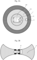
- Fig. 2A and Fig. 2B illustrate an example of the movable range of the work machine.
- Fig. 2A shows a movable range 24 of the hydraulic shovel 1.
- Fig. 2B shows a movable range 19 of the wheel loader 36.
- a movable range 24A for the front work unit 23 of the hydraulic shovel 1 is the range that the front work unit 23 can reach as the upper rotating structure rotates 360 degrees when the front work unit is taking the longest pose.
- the movable range 24B for the lower travelling structure 14 is the range that the vehicle body can reach in T seconds, for example, when the hydraulic shovel 1 travels.
- a movable range integrating the movable ranges 24A and 24B is defined as the movable range 24 for the hydraulic shovel 1.
- the movable range 19 of the wheel loader 36 is the range in which the wheel loader 36 can move in the front-rear direction in T seconds with the steering wheel turned to the limit to left or right.
- Fig. 3 is a block diagram illustrating a functional configuration example of the information presentation device according to the present embodiment.
- the information presentation device includes a current terrain information acquisition unit 25, an original terrain information acquisition unit 26, an overhead-view imaging processing unit 27, and the display unit (display device) 29.
- the overhead-view imaging processing unit 27 includes an overhead-view image synthesis unit 28.
- the information presentation device is composed of a computer, for example.
- a processor included in the computer reads from a memory (storage device; same below) a program for implementing the respective processing units (such as the current terrain information acquisition unit, the original terrain information acquisition unit, and the overhead-view imaging processing unit), and loads the program into an internal memory, to thereby implement the respective processing units.
- the information presentation device may be disposed at the operator's seat of the work machine 1, or may be disposed in a remote area (for example, a management office) separate from the work machine 1 and the imaging device 33.
- the current terrain is captured by the imaging device 33 or the like, such as a camera installed at the construction site 31.
- the current terrain information acquisition unit 25 Upon receiving images of the current terrain, the current terrain information acquisition unit 25 integrates and converts the images into an overhead-view image (Overhead-view image 1), and transmits the image to the overhead-view image synthesis unit 28.
- An overhead-view image (Overhead-view image 1)
- the original terrain information acquisition unit 26 acquires an overhead-view image (overhead-view image of the original terrain of the construction site 31) captured by the drone, satellite, or the like, or an image drawn based on a design drawing (overhead-view image of the original terrain: Overhead-view image 2).
- the overhead-view image synthesis unit 28 superimposes Overhead-view image 1, created based on the current terrain information, over Overhead-view image 2 of the construction site 31 acquired by the original terrain information acquisition unit 26, to synthesize an image.
- the overhead-view image synthesis unit 28 transmits the synthesized overhead-view image (Overhead-view image 3) to the display unit 29.
- the display unit 29 is for Overhead-view image 3 synthesized by the overhead-view image synthesis unit 28, and includes a display device, such as a monitor, and/or a display terminal, such as a smartphone, carried by the operator of the hydraulic shovel (work machine) 1, a site worker, a construction manager, or a site supervisor.
- a display device such as a monitor
- a display terminal such as a smartphone
- Fig. 4 shows an example of Overhead-view image 2 acquired by the original terrain information acquisition unit 26.
- a site worker uses an apparatus, such as a drone capable of capturing an overhead-view image, to capture an image prior to construction.
- the original terrain image may be drawn based on a design drawing.
- the construction site 31 is partitioned into the inside 31 of the construction site 31, the outside 32 of the construction site, and a fixed obstacle 30.
- the partitioning is implemented prior to the start of construction, and is not necessarily required to have a high update frequency.
- the method for partitioning which is required to be set at the initiative of the site worker or the construction manager, may use a learning function such as deep learning, and use an algorithm for automatically recognizing the boundaries of the fixed obstacle 30 and the construction site 31. Further, when the overhead-view image is captured/drawn, the coordinates of a reference point of the construction site 31 are determined in advance.
- Fig. 5 illustrates an example of Overhead-view image 1 acquired by the current terrain information acquisition unit 25.
- At least one imaging device 33 such as a camera, is disposed near the construction site 31 or inside the construction site 31, at a position and height allowing for the capturing of the inside 31 of the construction site 31. Then, the construction site 31 is captured by the imaging device 33.
- the position (coordinates) and height at which the imaging device 33 is disposed, and the angle of view and the line-of-sight direction of the imaging device 33 are registered in advance by the worker manually.
- data associating an apparatus capable of performing own position estimation such as a GNSS, with the imaging device 33 is automatically registered in the current terrain information acquisition unit 25.
- the current terrain information acquisition unit 25 stores (in the aforementioned memory) a modification parameter of the image captured by the imaging device 33, in advance for each imaging device 33.
- the modification parameter of the image is data that can be identified (determined) based on the installation position and the line-of-sight direction of the imaging device 33.
- the method for generating Overhead-view image 1 is not limited to the above. For example, triangulation may be performed with respect to a plurality of images acquired by the current terrain information acquisition unit 25, to create a three-dimensional image of the construction site 31, and then an overall overhead-view image (Overhead-view image 1) may be created based on the obtained three-dimensional image.
- Fig. 6 illustrates an example of Overhead-view image 3 generated by the overhead-view image synthesis unit 28 superimposing the current terrain information (Overhead-view image 1) over the original terrain information (Overhead-view image 2).
- the Overhead-view image 1 of the current terrain created by the current terrain information acquisition unit 25 is compared with the reference point of the original terrain information (Overhead-view image 2) based on the position information of each imaging device 33, and the synthesized positions are adjusted to generate Overhead-view image 3.
- Fig. 7 is a flowchart for describing in detail an overhead-view image generation process of generating Overhead-view image 3 according to the present embodiment.
- the actor is the respective processing units (the current terrain information acquisition unit 25, the original terrain information acquisition unit 26, and the overhead-view image synthesis unit 28).
- programs corresponding to the respective units are read from memory and implemented by the processor of the computer (information presentation device), as described above, the actor may be the processor.
- the original terrain information acquisition unit 26 acquires the overhead-view image captured by the drone or satellite, or the image drawn based on the design drawing (Overhead-view image 2), and transmits Overhead-view image 2 to the overhead-view image synthesis unit 28.
- the Overhead-view image 2 may be, for example, an image stored in a database or a storage device in advance, or an image that has been newly captured or obtained and input into the information presentation device by the operator or the construction manager.
- the current terrain information acquisition unit 25 receives the current terrain image captured by at least one imaging device 33 and transmitted therefrom.
- the current terrain information acquisition unit 25 integrates the images (images from a plurality of imaging devices 33) received in step 102 in alignment with a predetermined reference point defined in advance (for example, any desired pixel or region of at least one of the images), thereby converting the images into an overhead-view image (Overhead-view image 1). Then, the current terrain information acquisition unit 25 transmits the generated Overhead-view image 1 to the overhead-view image synthesis unit 28.
- the overhead-view image synthesis unit 28 synthesizes or converts Overhead-view image 2 received from the original terrain information acquisition unit 26 and Overhead-view image 1 received from the current terrain information acquisition unit 25 to generate a synthesized overhead-view image (Overhead-view image 3), and transmits the image to the display unit 29.
- the display unit 29 displays Overhead-view image 3 on a display screen. In this way, the operator, the construction manager, the worker of the hydraulic shovel (work machine) 1, a nearby worker, and/or the site supervisor can understand the situation of the construction site as viewed from above.
- the overhead-view image of the current terrain can be complemented when the information of the overhead-view image is lacking.
- the number of the imaging devices 33 available at the construction site 31 is limited, it is likely that a blind area 40 is present in the work site. In this case, unless the presence of the blind area 40 is presented to the operator of the hydraulic shovel (work machine) 1, it may be difficult to perform an operation (work) taking into consideration the likelihood that an obstacle (such as another work machine) may appear out of the blind area 40 of the fixed obstacle 30.
- the second embodiment provides an information presentation device and an information presentation method whereby, when a blind area (blind area 40 as will be described below) is present at the construction site 31, the blind area 40 can be presented to the operator of the hydraulic shovel (work machine) 1.
- a blind area blind area 40 as will be described below
- Fig. 8 to Fig. 11 the information presentation device according to the second embodiment of the present disclosure is described.
- signs similar to those of Fig. 1 to Fig. 7 designate similar components or processing units, and therefore redundant description is omitted.
- the information presentation device further comprises: a blind area computation unit 39 that computes the blind area 40 of the overhead-view image generated by the current terrain information acquisition unit 25; and a determination unit 38 that, in accordance with the distance to the computed blind area 40 or the area of the blind area 40, determines that the information of the overhead-view image of the current terrain is lacking.
- Fig. 8 is a block diagram illustrating a functional configuration example of the information presentation device according to the second embodiment.
- the blind area computation unit 39 based on the overhead-view image of the current terrain (Overhead-view image 1) created by the current terrain information acquisition unit 25, divides Overhead-view image 1 into a grid, and computes the area of cells located outside the capture range of the imaging device 33.
- the determination unit 38 determines whether the information of Overhead-view image 1 is lacking in accordance with the result of computation by the blind area computation unit 39. Specifically, if the area of the blind area 40 at the construction site 31 exceeds a certain threshold value for the entire area of the construction site 31, the determination unit 38 determines that the information (information necessary for safe operation of the work machine 1 (vehicle body)) is lacking. In this way, when the work machine (hydraulic shovel) 1 works near the blind area, for example, in view of the likelihood that an obstacle may appear unexpectedly out of the blind area 40 of the fixed obstacle 30 and may contact the front work unit 23 or a counter weight 11, a warning can be issued in advance when a mostly rotating or travelling operation is performed.
- the threshold value for the area of the blind area 40 may be set by the construction manager as desired.
- the position (coordinates) of the work machine 1 can be estimated by means of, e.g., a GNSS or the imaging device 33, it may be determined that the necessary information (information necessary for safe operation of the work machine 1 (vehicle body)) is lacking if the distance from the work machine 1 to the blind area 40 is less than or equal to a threshold value, such as within the movable range 24 of the work machine 1, and if the area of the relevant blind area 40 is greater than or equal to a certain area.
- the display unit 29 displays Overhead-view image 4 (overhead-view image incorporating the blind area) generated by performing, for example, a display process in which the blind area 40 portion of the overhead-view image (Overhead-view image 3) synthesizing Overhead-view image 1 and Overhead-view image 2 is filled. In this way, it becomes possible to visualize the blind area 40 of the construction site 31 to the operator, the construction manager, a nearby worker, and/or the site supervisor. In addition, if it is determined by the determination unit 38 that the necessary information is lacking, a warning such as "information lacking" is displayed on the display unit 29.
- the display unit 29 may implement the warning audibly, in addition to via a display device such as a monitor, or a display terminal such as a smartphone.
- the method for computing the blind area 40 (presence or absence of the blind area, position of the blind area, and extent (size) of the blind area) is described in detail.
- the imaging device 33 such as a camera
- the lines connecting the ends 30A and 30B of the fixed obstacle 30 and the center point of the imaging device 33 provide blind area lines 41
- the inside of the blind area lines 41 provides the blind area 40.
- the blind area 40 is equally divided into a grid or pixel units (thereby enabling identification of the coordinates constituting the blind area), whereby the area of the blind area 40 can be represented by the area for the number of the squares.
- the grid demarcations would have to be finer.
- the grid is determined to be a square constituting the blind area 40.
- the threshold value may be set as desired.
- the imaging device 33 such as a camera is installed at a position higher than the height of the fixed obstacle 30, a line connecting the top 30C of the fixed obstacle and the center point of the imaging device 33 provides a blind area line 41, whereby the blind area in the depth portion can be reduced.
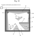
- Fig. 10 illustrates an example of Overhead-view image 4 (overhead-view image generated by incorporating the blind area into Overhead-view image 3) according to the second embodiment.
- the display unit 29 displays, on the display screen of the information presentation device, Overhead-view image 4 generated by superimposing the blind area 40 of the current terrain information acquisition unit 25 over Overhead-view image 3. Further, the display unit 29, if the area of the blind area 40 is large, displays "warning" on the display screen, thus warning about the likelihood that another obstacle (not shown) may appear out of the blind area 40.
- Fig. 11 is a flowchart for describing in detail the process of generating Overhead-view image 4 according to the second embodiment.
- the actor is the respective processing units (the current terrain information acquisition unit 25, the original terrain information acquisition unit 26, the blind area computation unit 39, the overhead-view image synthesis unit 28, and the determination unit 38).
- programs corresponding to the respective units are read from memory and implemented by the processor of the computer (information presentation device), as described above, the actor may be the processor.
- the original terrain information acquisition unit 26 acquires the overhead-view image captured by the drone or satellite, or the image drawn based on the design drawing (Overhead-view image 2), and transmits Overhead-view image 2 to the overhead-view image synthesis unit 28.
- Overhead-view image 2 may be, for example, an image stored in a database or a storage device in advance, or an image newly captured or obtained by the operator or the construction manager and input to the information presentation device.
- the current terrain information acquisition unit 25 receives the current terrain image captured by at least one imaging device 33 and transmitted therefrom.
- the current terrain information acquisition unit 25 integrates the images (a plurality of images from the imaging devices 33) received in step 202 in alignment with a predetermined reference point defined in advance (for example, any desired pixel or region of one of the images), thereby converting the images into an overhead-view image (Overhead-view image 1). Then, the current terrain information acquisition unit 25 transmits the generated Overhead-view image 1 to the blind area computation unit 39.
- the blind area computation unit 39 computes the presence or absence of the blind area 40 (see Fig. 9A to Fig. 9C ), the area of the blind area 40 (see Fig. 9A to C ), and the distance to the blind area 40 (distance: for example, the shortest distance from the movable range 24A or the movable range 24 of the work machines 1A and 1B to the blind area 40). Then, the blind area computation unit 39 transmits the information about the blind area 40 (presence/absence, area, and distance) to the overhead-view image synthesis unit 28, together with Overhead-view image 1.
- the overhead-view image synthesis unit 28 generates the synthesized overhead-view image (Overhead-view image 3) by synthesizing or converting Overhead-view image 2 received from the original terrain information acquisition unit 26 and Overhead-view image 1 that is received from the blind area computation unit 39 (or that may be received directly from the current terrain information acquisition unit 25), and further generates Overhead-view image 4 (overhead-view image incorporating the blind area) by synthesizing the blind area 40 received from the blind area computation unit 39 with Overhead-view image 3. Then, the overhead-view image synthesis unit 28 transmits Overhead-view image 4 and the information about the blind area 40 (for example, at least the area of the blind area among the presence or absence, area, and distance of the blind area) to the determination unit 38.
- the determination unit 38 determines whether the necessary information (information necessary for safe operation of the work machine 1 (vehicle body)) has been acquired. For example, it is determined that the necessary information has been acquired if the distance from the work machine 1 to the blind area 40 (the shortest distance from the movable range 24A or the movable range 24 of the work machines 1A and 1B to the blind area 40) is greater than a predetermined threshold value (distance threshold value), and the area of the blind area 40 is less than or equal to a predetermined threshold value. If it is determined that the necessary information has been acquired (Yes in step 206), the process proceeds to step 207. If it is determined that the necessary information has not been acquired (No in step 206), the proceeds to process step 208.
- a predetermined threshold value distance threshold value
- the display unit 29 displays Overhead-view image 4 on the display screen.
- the construction manager, the operator of the hydraulic shovel (work machine) 1, a nearby worker, and/or the site supervisor can understand the situation of the construction site as viewed from above, and can maneuver the work machine 1 at the construction site 31 safely.
- the display unit 29 displays Overhead-view image 4 on the display screen with "warning" (the word warning, or a mark or the like indicating danger) superimposed thereover.
- "warning" the word warning, or a mark or the like indicating danger
- Fig. 12 to Fig. 15 the information presentation device according to a third embodiment of the present disclosure is described.
- signs similar to those of Fig. 1 to Fig. 11 designate similar components or processing units, and therefore redundant description is omitted.
- the imaging device 33 is disposed around the construction site 31; it is determined whether necessary information is lacking from the area acquired of the blind area 40 in the current terrain; and then the operator, a nearby worker, and the site supervisor are warned.
- the third embodiment comprises a function whereby the data of an in-vehicle overhead-view image 48, which is created based on the images captured by the in-vehicle imaging device 33, is synthesized with (superimposed over) the current terrain information (Overhead-view image 1) to thereby reduce the area of the blind area 40.
- Fig. 12 is a block diagram illustrating a functional configuration example of the information presentation device according to the third embodiment.
- the information presentation device comprises, in addition to the configuration elements of Fig. 8 , a vehicle body orientation angle computation unit 43, a vehicle body position detection unit 44, an in-vehicle overhead-view image creating unit 45, and a display switching unit 47.
- the vehicle body orientation angle computation unit 43 based on the position information from the vehicle body position detection unit 44, acquires the orientation of the work machine 1 according to a construction site standard, and transmits the information about the orientation to an in-vehicle overhead-view image correction unit 46.
- the vehicle body position detection unit 44 identifies the position of the work machine 1 according to the construction site standard or a global coordinate standard, and transmits the information about the position to the in-vehicle overhead-view image correction unit 46.
- the in-vehicle overhead-view image creating unit 45 transmits an overhead-view image (hereafter referred to as an in-vehicle overhead-view image 48) created based on the in-vehicle imaging device 33 to the in-vehicle overhead-view image correction unit 46.
- Fig. 13 illustrates an example of the in-vehicle overhead-view image 48.
- the position and orientation of the in-vehicle overhead-view image 48 for synthesis with the overhead-view image of the current terrain vary depending on the position and orientation of the work machine 20. Accordingly, first, the position for synthesizing the in-vehicle overhead-view image 48 is identified from the positional relationship between the position information of the work machines 1A and 1B and the reference point of the construction site 31.
- image data is rotated by the in-vehicle overhead-view image correction unit 46 by the orientation angle of the work machines, based on the orientation information of the work machines 1A and 1B according to the construction site standard or the global coordinate standard. Further, the rotated image data is projected onto the overhead-view image in accordance with the acquired position of the work machines 1A and 1B and synthesized, whereby it becomes possible to display the in-vehicle overhead-view image 48 over the overhead-view image of the construction site.
- Fig. 14 illustrates an example of a synthesized Overhead-view image 5 according to the third embodiment.
- Overhead-view image 5 illustrated in Fig. 14 is an image obtained by reflecting the in-vehicle overhead-view image 48 in Overhead-view image 1, and further synthesizing Overhead-view image 2 therewith; that is, an image obtained by removing, from the blind area 40 of Overhead-view image 4 illustrated in Fig. 10 , the regions covered by the in-vehicle overhead-view image 48.
- the overhead-view image synthesis unit 28 further superimposes Overhead-view image 2 from the original terrain information acquisition unit 26 over the overhead-view image from the blind area computation unit 39 (the image obtained by superimposing the blind area 40 and the in-vehicle overhead-view image 48 over Overhead-view image 1), whereby Overhead-view image 5 can be generated.
- the display switching unit 47 can switch the in-vehicle overhead-view image 48 and Overhead-view image 5 (overhead-surroundings-view image) by means of a button or a touchscreen of the monitor.
- Fig. 15 is a flowchart for describing in detail the process of generating Overhead-view image 5 according to the third embodiment.
- the actor is the respective processing units (the current terrain information acquisition unit 25, the original terrain information acquisition unit 26, the blind area computation unit 39, the overhead-view image synthesis unit 28, the determination unit 38, the vehicle body orientation angle computation unit, the vehicle body position detection unit 44, the in-vehicle overhead-view image creating unit 45, and the display switching unit 47).
- the actor may be the processor.
- the original terrain information acquisition unit 26 acquires the overhead-view image captured by the drone or satellite, or the image drawn based on the design drawing (Overhead-view image 2), and transmits Overhead-view image 2 to the overhead-view image synthesis unit 28.
- the Overhead-view image 2 may be, for example, an image stored in a database or a storage device in advance, or an image newly captured or obtained by the operator or the construction manager and input to the information presentation device.
- the current terrain information acquisition unit 25 receives the current terrain image captured by at least one imaging device 33 and transmitted therefrom.
- the current terrain information acquisition unit 25 integrates the images received in step 302 (a plurality of images from the imaging devices 33) in alignment with a predetermined reference point defined in advance (for example, any desired pixel or region of one of the images) and converts them into an overhead-view image (Overhead-view image 1).
- the current terrain information acquisition unit 25 then transmits the generated Overhead-view image 1 to the blind area computation unit 39.
- the in-vehicle overhead-view image correction unit 46 receives the in-vehicle overhead-view image of the work machine 1 from the in-vehicle overhead-view image creating unit 45, the information about the orientation angle of the work machine 1 from the vehicle body orientation angle computation unit 43, and the information about the position of the work machine 1 from the information from the vehicle body position detection unit 44. Then, the in-vehicle overhead-view image correction unit 46 corrects the in-vehicle overhead-view image of the work machine 1 based on the information about the orientation angle and position of the work machine 1, and transmits the corrected in-vehicle overhead-view image to the overhead-view image synthesis unit 28.
- the blind area computation unit 39 computes the presence or absence of the blind area 40 (see Fig. 9A to Fig. 9C ), the area of the blind area 40 (see Fig. 9A to Fig. 9C ), and the distance to the blind area 40 (distance: for example, the shortest distance from the movable range 24A or the movable range 24 of the work machines 1A and 1B to the blind area 40). Then, the blind area computation unit 39 transmits the information about the blind area 40 (presence/absence, area, and distance) to the overhead-view image synthesis unit 28, together with Overhead-view image 1.
- the overhead-view image synthesis unit 28 generates Overhead-view image 5 (see Fig. 14 ) reflecting the blind area 40 and the in-vehicle overhead-view image, based on (by synthesizing) Overhead-view image 2 received from the original terrain information acquisition unit 26, Overhead-view image 1 and the information about the blind area 40 received from the blind area computation unit 39, and the in-vehicle overhead-view image (corrected in-vehicle overhead-view image) 48 received from the in-vehicle overhead-view image correction unit 46. Then, the overhead-view image synthesis unit 28 transmits Overhead-view image 5 to the determination unit 38.
- the determination unit 38 determines whether the necessary information (information necessary for safe operation of the work machine 1 (vehicle body)) has been acquired. For example, it is determined that the necessary information has been acquired if the distance from the work machine 1 to the blind area 40 (the shortest distance from the movable range 24A or the movable range 24 of the work machines 1A and 1B to the blind area 40) is greater than a predetermined threshold value (distance threshold value), and the area of the blind area 40 is less than or equal to a predetermined threshold value. If it is determined that the necessary information has been acquired (Yes in step 307), the process proceeds to step 308. If it is determined that the necessary information has not been acquired (No in step 307), the process proceeds to step 309.
- the display unit 29 displays Overhead-view image 5 on the display screen.
- the construction manager, the operator of the hydraulic shovel (work machine) 1, a nearby worker, and/or the site supervisor can understand the situation of the construction site as viewed from above, and can safely maneuver the work machine 1 at the construction site 31.
- the display unit 29 displays Overhead-view image 5 on the display screen with "warning" (the word warning, or a mark or the like indicating danger) superimposed thereover.
- "warning" the word warning, or a mark or the like indicating danger
- the information presentation device generates a first synthesized overhead-view image (Overhead-view image 3) by superimposing the first overhead-view image (Overhead-view image 1) representing the current terrain of the construction site 31 as viewed from above, and the second overhead-view image (Overhead-view image 2), which is acquired by a method (for example, capturing by a drone or a satellite) other than capturing by the imaging device 33 installed at the construction site, and which represents the original terrain of the construction site as viewed from above; and outputs (displays on the display screen of the display unit 29) the first synthesized overhead-view image.
- a method for example, capturing by a drone or a satellite
- the overhead-view image of the current construction site as a whole is generated using Overhead-view image 2 complementarily, which is originally present in the current image acquired by the imaging device, it is possible to provide a helpful overhead-view image of the construction site to the worker, even when the number of the imaging devices 33 installed at the construction site is small.
- the information presentation device uses the first overhead-view image (Overhead-view image 1) acquired by the imaging device 33, identifies the blind area 40 at the construction site, generates the second synthesized overhead-view image (Overhead-view image 4) by reflecting the image of the blind area 40 in the first synthesized overhead-view image (Overhead-view image 3), and then outputs the second synthesized overhead-view image.
- the likelihood of another work machine or the like appearing out of the blind area 40 can be understood in an overhead-view manner, so that the work machine can be operated safely.
- the information presentation device generates the third synthesized overhead-view image (Overhead-view image 5) by reflecting the in-vehicle overhead-view image generated based on the image captured by the in-vehicle imaging device installed in the work machine 1 in the second synthesized overhead-view image (Overhead-view image 4), and then outputs the third synthesized overhead-view image.
- the area of the blind area 40 can be reduced, so that the work machine can be maneuvered safely.
- the functions of the embodiments of the present disclosure may be implemented by the program code of software.
- a storage medium having the program code recorded therein may be provided to a system or a device, and a computer (or a CPU or an MPU) of the system or the device may read out the program code stored in the storage medium.
- the program code per se read out from the storage medium implements the above-described functions of the embodiments, and the program code per se and the storage medium having the same stored therein constitute the present disclosure.
- Examples of the storage medium for supplying such program code include a flexible disc, a CD-ROM, a DVD-ROM, a hard disk, an optical disk, a magneto optical disk, a CD-R, magnetic tape, a nonvolatile memory card, and a ROM.
- some or all of actual processes may be executed by an operating system (OS), for example, running on a computer, and the above-described functions of the embodiments may be implemented by the processes.
- OS operating system
- the program code read from the storage medium may be written to a memory on the computer, and then, based on the instructions of the program code, some or all of actual processes may be executed by the CPU of the computer, for example, and the above-described functions of the embodiments may be implemented by the processes.
- program code of software for implementing the functions of the embodiments may be delivered via a network, and stored in a storage means such as a hard disk or a memory of the system or device, or in a storage medium such as a CD-RW or a CD-R.
- a storage means such as a hard disk or a memory of the system or device
- a storage medium such as a CD-RW or a CD-R.
- the computer (or a CPU or an MPU) of the system or device may read and execute the program code stored in the storage means or the storage medium.
- control lines and information lines that are indicated are those considered necessary for illustrative purposes, and not all control lines or information lines of a product are necessarily indicated. All configurations may be interconnected.
Landscapes
- Engineering & Computer Science (AREA)
- Civil Engineering (AREA)
- Structural Engineering (AREA)
- General Engineering & Computer Science (AREA)
- Mining & Mineral Resources (AREA)
- Physics & Mathematics (AREA)
- Theoretical Computer Science (AREA)
- General Physics & Mathematics (AREA)
- Multimedia (AREA)
- Image Processing (AREA)
- Component Parts Of Construction Machinery (AREA)
- Closed-Circuit Television Systems (AREA)
- Computer Vision & Pattern Recognition (AREA)
- Image Analysis (AREA)
- Geometry (AREA)
- Signal Processing (AREA)
Abstract
Description
- The present disclosure relates to an information presentation device.
- Conventionally, information presentation devices are known in which, at a construction site where a plurality of machines, such as work machines and transport vehicles, are present, an operator of a work machine is enabled to recognize the position of another work machine or transport vehicle that is present nearby. For example,
Patent Literature 1 discloses an information presentation device that: identifies the position of each of a plurality of vehicles based on images captured by a plurality of imaging devices installed at a construction site; and outputs a signal for causing the position of, among the identified vehicles, another vehicle of which the distance from a vehicle designated as desired is less than a threshold value, to be displayed over an overhead-view image of the construction site. - Patent Literature 1:
JP 2019-151968 A - However, with the configuration described in
Patent Literature 1, it may be difficult to synthesize the overhead-view image when, for example, the number of the imaging devices available at the construction site is limited due to installation cost. This is because an image covering the entire area of the construction site cannot be synthesized. As a result, the plurality of vehicles at the construction site cannot be managed efficiently. - The present disclosure has been made in view of such a circumstance, and proposes a technology for presenting an overhead-view image of a work site to an operator of a work machine even when the number of imaging devices at a construction site is lacking.
- In order to solve the problem, the present disclosure proposes an information presentation device for generating and outputting a terrain image relating to a construction site. The information presentation device includes a storage device that stores a program for performing a predetermined imaging process on the terrain image, and a processor for reading the program from the storage device and generating the terrain image. The processor performs: a process of using an image of the construction site acquired by at least one imaging device installed at the construction site, to acquire a first overhead-view image representing a current terrain of the construction site as viewed from above; a process of acquiring a second overhead-view image acquired by a method other than capturing by the imaging device installed at the construction site, and representing an original terrain of the construction site as viewed from above; and an image synthesis process of superimposing the first overhead-view image and the second overhead-view image to generate a first synthesized overhead-view image.
- Additional features related to the present disclosure will become apparent from the descriptions provided herein and the attached drawings. Aspects of the present disclosure are achieved and realized by elements, various combinations of elements, the following descriptions, and the embodiments set forth in the attached claims. The descriptions provided herein are merely by way of typical examples, and are not intended to limit the scope of the claims or application examples of the present disclosure in any sense.
- According to the present disclosure, an overhead-view image of a work site can be generated and presented to an operator of a work machine even when the number of imaging devices at a construction site is lacking.
-
-
Fig. 1 illustrates a schematic configuration example of a work machine. -
Fig. 2A illustrates amovable range 24 of ahydraulic shovel 1. -
Fig. 2B illustrates amovable range 19 of awheel loader 36. -
Fig. 3 is a block diagram illustrating a functional configuration example of an information presentation device according to the present embodiment. -
Fig. 4 illustrates an example of Overhead-view image 2 acquired by an original terraininformation acquisition unit 26. -
Fig. 5 illustrates an example of Overhead-view image 1 acquired by a current terraininformation acquisition unit 25. -
Fig. 6 illustrates an example of Overhead-view image 3 generated by an overhead-viewimage synthesis unit 28 superimposing current terrain information (Overhead-view image 1) over original terrain information (Overhead-view image 2). -
Fig. 7 is a flowchart for describing in detail an overhead-view image generation process of generating Overhead-view image 3 according to the present embodiment. -
Fig. 8 is a block diagram illustrating a functional configuration example of an information presentation device according to a second embodiment. -
Fig. 9A is afigure (1 ) for describing a method for computing a blind area 40 (the presence or absence of a blind area, position of a blind area, and extent (size) of a blind area). -
Fig. 9B is afigure (2 ) for describing a method for computing the blind area 40 (presence or absence of a blind area, position of a blind area, and extent (size) of a blind area). -
Fig. 9C is afigure (3 ) for describing a method for computing the blind area 40 (presence or absence of a blind area, position of a blind area, and extent (size) of a blind area). -
Fig. 10 illustrates an example of Overhead-view image 4 (an overhead-view image generated by incorporating the blind area into Overhead-view image 3) according to the second embodiment. -
Fig. 11 is a flowchart for describing in detail a process of generating Overhead-view image 4 according to the second embodiment. -
Fig. 12 is a block diagram illustrating a functional configuration example of an information presentation device according to a third embodiment. -
Fig. 13 illustrates an example of an in-vehicle overhead-view image 48. -
Fig. 14 illustrates an example of a synthesized Overhead-view image 5 according to the third embodiment. -
Fig. 15 is a flowchart for describing in detail a process of generating Overhead-view image 5 according to the third embodiment. -
Fig. 16 illustrates a configuration example of an overhead-view image providing system according to the present embodiments (first to third embodiments). - The first to third embodiments of the present disclosure describe information presentation technologies for generating and outputting an overhead view terrain image of a construction site. In the following, reference is made to the attached drawings to describe the embodiments of the present disclosure. In the attached drawings, functionally similar elements may be shown with similar numerals. While the attached drawings show specific embodiments and implementation examples in accordance with the principles of the present disclosure, these are for facilitating an understanding of the present disclosure, and are not to be used to interpret the present disclosure in a limited sense.
- While the present embodiment is described in sufficient detail to enable a person skilled in the art to practice the present disclosure, it is to be understood that other implementations and modes are also possible, and that changes in configuration or structure and various substitutions of elements may be made without departing from the scope of the technical concepts and spirit of the present disclosure. Accordingly, the following description should not be taken in a limited sense.
- Further, as will be described below, the embodiments of the present disclosure may be implemented by software running on a general-purpose computer, or may be implemented by dedicated hardware or by a combination of software and hardware.
-
Fig. 16 illustrates a configuration example of an overhead-view image providing system (also referred to as an information providing system) according to the present embodiment (including a second and a third embodiment as will be described below). - The overhead-view image providing system comprises: a
work machine 1 having a communication device; at least one imaging device (camera) 33A to 33B installed at aconstruction site 31; a computer (information presentation device) that generates and outputs various overhead-view images of theconstruction site 31; a drone (corresponding to an original terrain information acquisition unit 26) for capturing an overhead-view image of an original terrain (the terrain before construction materials and thework machine 1 are arranged therein) of theconstruction site 31; a display unit (display device) 29 that displays the generated overhead-view image; and acommunication device 49. - While the system uses an overhead-view image (Overhead-
view image 2 as will be described below) captured by the drone (corresponding to the original terrain information acquisition unit 26), the system may use a satellite image captured by a satellite or the like, as Overhead-view image 2. - In
Fig. 16 , while the display unit (display device) 29 is disposed remotely from the computer (information presentation device), thedisplay unit 29 may constitute a part of the computer (information presentation device). The computer (information presentation device) may be installed outside (including a remote area) theconstruction site 31 so that a manager located away from theconstruction site 31 can confirm the overhead-view image, or the computer may be disposed at the operator's seat of thework machine 1 so that the operator can confirm the overhead-view image (or both). The information presentation device may be disposed outside theconstruction site 31, and only thedisplay unit 29 may be installed in thework machine 1. When the information presentation device and thedisplay unit 29 are disposed away from each other, as illustrated inFig. 16 , they may be configured to be able to communicate with each other via a network. -
Fig. 1 illustrates a schematic configuration example of the work machine. In the present embodiment, ahydraulic shovel 1 is described as an example of the work machine. - The
hydraulic shovel 1 is composed of a lower travellingstructure 14 on which anupper travelling structure 15 is mounted via arotating mechanism 16. Therotating mechanism 16 includes a hydraulic motor, and performs a rotating operation of the upper travellingstructure 15 in clockwise or anticlockwise direction. The upper travellingstructure 15 has aboom 8 attached thereto. Theboom 8 is pivotally moved by a hydraulically drivenboom cylinder 5 in an up-down direction with respect to the upper travellingstructure 15. Anarm 9 is attached to the tip-end of theboom 8. Thearm 9 is pivotally moved by a hydraulically drivenarm cylinder 6 in a front-rear direction with respect to theboom 8. Abucket 10 is attached to the tip-end of thearm 9. Thebucket 10 is pivotally moved by a hydraulically drivenbucket cylinder 7 with respect to thearm 9. Further, acab 2 for housing the operator is mounted on the upper travellingstructure 15. As used herein, theboom 8, thearm 9, and thebucket 10 may be collectively referred to as afront work unit 23. Thefront work unit 23 rotates around a center ofrotation 17 together with the upperrotating structure 15. Further, the distance from the center ofrotation 17 to the tip-end of thefront work unit 23 varies as theboom 8, thearm 9, or thebucket 10 is pivotally moved. The upper travellingstructure 15 rotates around the center ofrotation 17. Anattachment 18 is attached to the upper travellingstructure 15. - The
boom 8 pivotally moves up and down around a center of pivotal motion which is parallel to a y-axis. Thearm 9 is attached to the tip-end of theboom 8. Thebucket 10 is attached to the tip-end of thearm 9. - For a vehicle body
position detection unit 44, an apparatus capable of acquiring an own position, such as a GNSS, is used. An orientation angle of a vehicle body is computed by a vehicle body orientationangle computation unit 43. -
Fig. 2A and Fig. 2B illustrate an example of the movable range of the work machine.Fig. 2A shows amovable range 24 of thehydraulic shovel 1.Fig. 2B shows amovable range 19 of thewheel loader 36. - In
Fig. 2A , amovable range 24A for thefront work unit 23 of thehydraulic shovel 1 is the range that thefront work unit 23 can reach as the upper rotating structure rotates 360 degrees when the front work unit is taking the longest pose. Further, themovable range 24B for the lower travellingstructure 14 is the range that the vehicle body can reach in T seconds, for example, when thehydraulic shovel 1 travels. A movable range integrating themovable ranges movable range 24 for thehydraulic shovel 1. Further, inFig. 2B , themovable range 19 of thewheel loader 36 is the range in which thewheel loader 36 can move in the front-rear direction in T seconds with the steering wheel turned to the limit to left or right. -
Fig. 3 is a block diagram illustrating a functional configuration example of the information presentation device according to the present embodiment. - The information presentation device includes a current terrain
information acquisition unit 25, an original terraininformation acquisition unit 26, an overhead-viewimaging processing unit 27, and the display unit (display device) 29. The overhead-viewimaging processing unit 27 includes an overhead-viewimage synthesis unit 28. The information presentation device is composed of a computer, for example. A processor included in the computer reads from a memory (storage device; same below) a program for implementing the respective processing units (such as the current terrain information acquisition unit, the original terrain information acquisition unit, and the overhead-view imaging processing unit), and loads the program into an internal memory, to thereby implement the respective processing units. The information presentation device may be disposed at the operator's seat of thework machine 1, or may be disposed in a remote area (for example, a management office) separate from thework machine 1 and theimaging device 33. - The current terrain is captured by the
imaging device 33 or the like, such as a camera installed at theconstruction site 31. Upon receiving images of the current terrain, the current terraininformation acquisition unit 25 integrates and converts the images into an overhead-view image (Overhead-view image 1), and transmits the image to the overhead-viewimage synthesis unit 28. - The original terrain
information acquisition unit 26 acquires an overhead-view image (overhead-view image of the original terrain of the construction site 31) captured by the drone, satellite, or the like, or an image drawn based on a design drawing (overhead-view image of the original terrain: Overhead-view image 2). - The overhead-view
image synthesis unit 28 superimposes Overhead-view image 1, created based on the current terrain information, over Overhead-view image 2 of theconstruction site 31 acquired by the original terraininformation acquisition unit 26, to synthesize an image. The overhead-viewimage synthesis unit 28 transmits the synthesized overhead-view image (Overhead-view image 3) to thedisplay unit 29. - The
display unit 29 is for Overhead-view image 3 synthesized by the overhead-viewimage synthesis unit 28, and includes a display device, such as a monitor, and/or a display terminal, such as a smartphone, carried by the operator of the hydraulic shovel (work machine) 1, a site worker, a construction manager, or a site supervisor. -
Fig. 4 shows an example of Overhead-view image 2 acquired by the original terraininformation acquisition unit 26. A site worker uses an apparatus, such as a drone capable of capturing an overhead-view image, to capture an image prior to construction. The original terrain image may be drawn based on a design drawing. In the original terrain image, theconstruction site 31 is partitioned into the inside 31 of theconstruction site 31, the outside 32 of the construction site, and a fixedobstacle 30. The partitioning is implemented prior to the start of construction, and is not necessarily required to have a high update frequency. The method for partitioning, which is required to be set at the initiative of the site worker or the construction manager, may use a learning function such as deep learning, and use an algorithm for automatically recognizing the boundaries of the fixedobstacle 30 and theconstruction site 31. Further, when the overhead-view image is captured/drawn, the coordinates of a reference point of theconstruction site 31 are determined in advance. -
Fig. 5 illustrates an example of Overhead-view image 1 acquired by the current terraininformation acquisition unit 25. At least oneimaging device 33, such as a camera, is disposed near theconstruction site 31 or inside theconstruction site 31, at a position and height allowing for the capturing of the inside 31 of theconstruction site 31. Then, theconstruction site 31 is captured by theimaging device 33. The position (coordinates) and height at which theimaging device 33 is disposed, and the angle of view and the line-of-sight direction of theimaging device 33 are registered in advance by the worker manually. Alternatively, data associating an apparatus capable of performing own position estimation, such as a GNSS, with theimaging device 33 is automatically registered in the current terraininformation acquisition unit 25. - Further, the current terrain information acquisition unit 25 (the aforementioned computer) stores (in the aforementioned memory) a modification parameter of the image captured by the
imaging device 33, in advance for eachimaging device 33. The modification parameter of the image is data that can be identified (determined) based on the installation position and the line-of-sight direction of theimaging device 33. It is noted that the method for generating Overhead-view image 1 is not limited to the above. For example, triangulation may be performed with respect to a plurality of images acquired by the current terraininformation acquisition unit 25, to create a three-dimensional image of theconstruction site 31, and then an overall overhead-view image (Overhead-view image 1) may be created based on the obtained three-dimensional image. -
Fig. 6 illustrates an example of Overhead-view image 3 generated by the overhead-viewimage synthesis unit 28 superimposing the current terrain information (Overhead-view image 1) over the original terrain information (Overhead-view image 2). - The Overhead-
view image 1 of the current terrain created by the current terraininformation acquisition unit 25 is compared with the reference point of the original terrain information (Overhead-view image 2) based on the position information of eachimaging device 33, and the synthesized positions are adjusted to generate Overhead-view image 3. -
Fig. 7 is a flowchart for describing in detail an overhead-view image generation process of generating Overhead-view image 3 according to the present embodiment. In the following steps, the actor is the respective processing units (the current terraininformation acquisition unit 25, the original terraininformation acquisition unit 26, and the overhead-view image synthesis unit 28). However, because programs corresponding to the respective units are read from memory and implemented by the processor of the computer (information presentation device), as described above, the actor may be the processor. - The original terrain
information acquisition unit 26 acquires the overhead-view image captured by the drone or satellite, or the image drawn based on the design drawing (Overhead-view image 2), and transmits Overhead-view image 2 to the overhead-viewimage synthesis unit 28. The Overhead-view image 2 may be, for example, an image stored in a database or a storage device in advance, or an image that has been newly captured or obtained and input into the information presentation device by the operator or the construction manager. - The current terrain
information acquisition unit 25 receives the current terrain image captured by at least oneimaging device 33 and transmitted therefrom. - The current terrain
information acquisition unit 25 integrates the images (images from a plurality of imaging devices 33) received instep 102 in alignment with a predetermined reference point defined in advance (for example, any desired pixel or region of at least one of the images), thereby converting the images into an overhead-view image (Overhead-view image 1). Then, the current terraininformation acquisition unit 25 transmits the generated Overhead-view image 1 to the overhead-viewimage synthesis unit 28. - The overhead-view
image synthesis unit 28 synthesizes or converts Overhead-view image 2 received from the original terraininformation acquisition unit 26 and Overhead-view image 1 received from the current terraininformation acquisition unit 25 to generate a synthesized overhead-view image (Overhead-view image 3), and transmits the image to thedisplay unit 29. - The
display unit 29 displays Overhead-view image 3 on a display screen. In this way, the operator, the construction manager, the worker of the hydraulic shovel (work machine) 1, a nearby worker, and/or the site supervisor can understand the situation of the construction site as viewed from above. - Thus, by superimposing the overhead-view image of the current terrain over the overhead-view image of the original terrain, the overhead-view image of the current terrain can be complemented when the information of the overhead-view image is lacking.
- If the number of the
imaging devices 33 available at theconstruction site 31 is limited, it is likely that ablind area 40 is present in the work site. In this case, unless the presence of theblind area 40 is presented to the operator of the hydraulic shovel (work machine) 1, it may be difficult to perform an operation (work) taking into consideration the likelihood that an obstacle (such as another work machine) may appear out of theblind area 40 of the fixedobstacle 30. - In view of the above, the second embodiment provides an information presentation device and an information presentation method whereby, when a blind area (
blind area 40 as will be described below) is present at theconstruction site 31, theblind area 40 can be presented to the operator of the hydraulic shovel (work machine) 1. - With reference to
Fig. 8 to Fig. 11 , the information presentation device according to the second embodiment of the present disclosure is described. InFig. 8 to Fig. 11 , signs similar to those ofFig. 1 to Fig. 7 designate similar components or processing units, and therefore redundant description is omitted. - In the first embodiment, the overhead-view image of the current terrain is superimposed over the overhead-view image of the original terrain. In contrast, in the second embodiment, the information presentation device further comprises: a blind
area computation unit 39 that computes theblind area 40 of the overhead-view image generated by the current terraininformation acquisition unit 25; and adetermination unit 38 that, in accordance with the distance to the computedblind area 40 or the area of theblind area 40, determines that the information of the overhead-view image of the current terrain is lacking. -
Fig. 8 is a block diagram illustrating a functional configuration example of the information presentation device according to the second embodiment. For example, in the information presentation device, the blindarea computation unit 39, based on the overhead-view image of the current terrain (Overhead-view image 1) created by the current terraininformation acquisition unit 25, divides Overhead-view image 1 into a grid, and computes the area of cells located outside the capture range of theimaging device 33. Alternatively, it is also possible to estimate the range of theblind area 40 in detail from the position, height, line of sight direction, and angle of view of theimaging device 33. - The
determination unit 38 determines whether the information of Overhead-view image 1 is lacking in accordance with the result of computation by the blindarea computation unit 39. Specifically, if the area of theblind area 40 at theconstruction site 31 exceeds a certain threshold value for the entire area of theconstruction site 31, thedetermination unit 38 determines that the information (information necessary for safe operation of the work machine 1 (vehicle body)) is lacking. In this way, when the work machine (hydraulic shovel) 1 works near the blind area, for example, in view of the likelihood that an obstacle may appear unexpectedly out of theblind area 40 of the fixedobstacle 30 and may contact thefront work unit 23 or acounter weight 11, a warning can be issued in advance when a mostly rotating or travelling operation is performed. The threshold value for the area of theblind area 40 may be set by the construction manager as desired. When the position (coordinates) of thework machine 1 can be estimated by means of, e.g., a GNSS or theimaging device 33, it may be determined that the necessary information (information necessary for safe operation of the work machine 1 (vehicle body)) is lacking if the distance from thework machine 1 to theblind area 40 is less than or equal to a threshold value, such as within themovable range 24 of thework machine 1, and if the area of the relevantblind area 40 is greater than or equal to a certain area. - The
display unit 29 displays Overhead-view image 4 (overhead-view image incorporating the blind area) generated by performing, for example, a display process in which theblind area 40 portion of the overhead-view image (Overhead-view image 3) synthesizing Overhead-view image 1 and Overhead-view image 2 is filled. In this way, it becomes possible to visualize theblind area 40 of theconstruction site 31 to the operator, the construction manager, a nearby worker, and/or the site supervisor. In addition, if it is determined by thedetermination unit 38 that the necessary information is lacking, a warning such as "information lacking" is displayed on thedisplay unit 29. Thedisplay unit 29 may implement the warning audibly, in addition to via a display device such as a monitor, or a display terminal such as a smartphone. - With reference to
Fig. 9A to Fig. 9C , the method for computing the blind area 40 (presence or absence of the blind area, position of the blind area, and extent (size) of the blind area) is described in detail. First, when the fixedobstacle 30 is captured by theimaging device 33 such as a camera, the lines connecting theends obstacle 30 and the center point of theimaging device 33 provideblind area lines 41, and the inside of theblind area lines 41 provides theblind area 40. Then, as illustrated inFig. 9B , theblind area 40 is equally divided into a grid or pixel units (thereby enabling identification of the coordinates constituting the blind area), whereby the area of theblind area 40 can be represented by the area for the number of the squares. Accordingly, if it is desired to determine the area of theblind area 40 more precisely, the grid demarcations would have to be finer. When the area inside the blind area lines 41 (portion hidden as the blind area) per square (grid) is greater than or equal to a threshold value, the grid is determined to be a square constituting theblind area 40. The threshold value may be set as desired. - When the
imaging device 33 such as a camera is installed at a position higher than the height of the fixedobstacle 30, a line connecting the top 30C of the fixed obstacle and the center point of theimaging device 33 provides ablind area line 41, whereby the blind area in the depth portion can be reduced. - Thus, by three-dimensionally identifying the
blind area 40, it becomes possible to determine accurately whether thework machine 1 can be safely operated. -
Fig. 10 illustrates an example of Overhead-view image 4 (overhead-view image generated by incorporating the blind area into Overhead-view image 3) according to the second embodiment. - As illustrated in
Fig. 10 , thedisplay unit 29 displays, on the display screen of the information presentation device, Overhead-view image 4 generated by superimposing theblind area 40 of the current terraininformation acquisition unit 25 over Overhead-view image 3. Further, thedisplay unit 29, if the area of theblind area 40 is large, displays "warning" on the display screen, thus warning about the likelihood that another obstacle (not shown) may appear out of theblind area 40. -
Fig. 11 is a flowchart for describing in detail the process of generating Overhead-view image 4 according to the second embodiment. In the steps described below, the actor is the respective processing units (the current terraininformation acquisition unit 25, the original terraininformation acquisition unit 26, the blindarea computation unit 39, the overhead-viewimage synthesis unit 28, and the determination unit 38). However, because programs corresponding to the respective units are read from memory and implemented by the processor of the computer (information presentation device), as described above, the actor may be the processor. - The original terrain
information acquisition unit 26 acquires the overhead-view image captured by the drone or satellite, or the image drawn based on the design drawing (Overhead-view image 2), and transmits Overhead-view image 2 to the overhead-viewimage synthesis unit 28. Overhead-view image 2 may be, for example, an image stored in a database or a storage device in advance, or an image newly captured or obtained by the operator or the construction manager and input to the information presentation device. - The current terrain
information acquisition unit 25 receives the current terrain image captured by at least oneimaging device 33 and transmitted therefrom. - The current terrain
information acquisition unit 25 integrates the images (a plurality of images from the imaging devices 33) received in step 202 in alignment with a predetermined reference point defined in advance (for example, any desired pixel or region of one of the images), thereby converting the images into an overhead-view image (Overhead-view image 1). Then, the current terraininformation acquisition unit 25 transmits the generated Overhead-view image 1 to the blindarea computation unit 39. - The blind
area computation unit 39 computes the presence or absence of the blind area 40 (seeFig. 9A to Fig. 9C ), the area of the blind area 40 (seeFig. 9A to C ), and the distance to the blind area 40 (distance: for example, the shortest distance from themovable range 24A or themovable range 24 of thework machines area computation unit 39 transmits the information about the blind area 40 (presence/absence, area, and distance) to the overhead-viewimage synthesis unit 28, together with Overhead-view image 1. - The overhead-view
image synthesis unit 28 generates the synthesized overhead-view image (Overhead-view image 3) by synthesizing or converting Overhead-view image 2 received from the original terraininformation acquisition unit 26 and Overhead-view image 1 that is received from the blind area computation unit 39 (or that may be received directly from the current terrain information acquisition unit 25), and further generates Overhead-view image 4 (overhead-view image incorporating the blind area) by synthesizing theblind area 40 received from the blindarea computation unit 39 with Overhead-view image 3. Then, the overhead-viewimage synthesis unit 28 transmits Overhead-view image 4 and the information about the blind area 40 (for example, at least the area of the blind area among the presence or absence, area, and distance of the blind area) to thedetermination unit 38. - The
determination unit 38, based on the information received from the overhead-viewimage synthesis unit 28, determines whether the necessary information (information necessary for safe operation of the work machine 1 (vehicle body)) has been acquired. For example, it is determined that the necessary information has been acquired if the distance from thework machine 1 to the blind area 40 (the shortest distance from themovable range 24A or themovable range 24 of thework machines blind area 40 is less than or equal to a predetermined threshold value. If it is determined that the necessary information has been acquired (Yes in step 206), the process proceeds to step 207. If it is determined that the necessary information has not been acquired (No in step 206), the proceeds to processstep 208. - The
display unit 29 displays Overhead-view image 4 on the display screen. In this way, the construction manager, the operator of the hydraulic shovel (work machine) 1, a nearby worker, and/or the site supervisor can understand the situation of the construction site as viewed from above, and can maneuver thework machine 1 at theconstruction site 31 safely. - The
display unit 29 displays Overhead-view image 4 on the display screen with "warning" (the word warning, or a mark or the like indicating danger) superimposed thereover. In this way, the construction manager, the operator of the hydraulic shovel (work machine) 1, a nearby worker, and/or the site supervisor can understand the situation of the construction site as viewed from above, and can understand the risk of maneuvering thework machine 1 at theconstruction site 31. - Thus, by computing the area of the
blind area 40 at theconstruction site 31 and warning the operator, a nearby worker, and the site supervisor about a lack of necessary information, it becomes possible to implement an operation taking into consideration the likelihood that an obstacle may appear out of theblind area 40 of the fixedobstacle 30. Further, by displaying theblind area 40 on thedisplay unit 29, it becomes possible to prompt a change in the arrangement of the current terraininformation acquisition unit 25. - With reference to
Fig. 12 to Fig. 15 , the information presentation device according to a third embodiment of the present disclosure is described. InFig. 12 to Fig. 15 , signs similar to those ofFig. 1 to Fig. 11 designate similar components or processing units, and therefore redundant description is omitted. - In the second embodiment, the
imaging device 33 is disposed around theconstruction site 31; it is determined whether necessary information is lacking from the area acquired of theblind area 40 in the current terrain; and then the operator, a nearby worker, and the site supervisor are warned. In contrast, the third embodiment comprises a function whereby the data of an in-vehicle overhead-view image 48, which is created based on the images captured by the in-vehicle imaging device 33, is synthesized with (superimposed over) the current terrain information (Overhead-view image 1) to thereby reduce the area of theblind area 40. -
Fig. 12 is a block diagram illustrating a functional configuration example of the information presentation device according to the third embodiment. As illustrated inFig. 12 , the information presentation device comprises, in addition to the configuration elements ofFig. 8 , a vehicle body orientationangle computation unit 43, a vehicle bodyposition detection unit 44, an in-vehicle overhead-viewimage creating unit 45, and adisplay switching unit 47. - The vehicle body orientation
angle computation unit 43, based on the position information from the vehicle bodyposition detection unit 44, acquires the orientation of thework machine 1 according to a construction site standard, and transmits the information about the orientation to an in-vehicle overhead-viewimage correction unit 46. The vehicle bodyposition detection unit 44 identifies the position of thework machine 1 according to the construction site standard or a global coordinate standard, and transmits the information about the position to the in-vehicle overhead-viewimage correction unit 46. The in-vehicle overhead-viewimage creating unit 45 transmits an overhead-view image (hereafter referred to as an in-vehicle overhead-view image 48) created based on the in-vehicle imaging device 33 to the in-vehicle overhead-viewimage correction unit 46. -
Fig. 13 illustrates an example of the in-vehicle overhead-view image 48. Here, the position and orientation of the in-vehicle overhead-view image 48 for synthesis with the overhead-view image of the current terrain vary depending on the position and orientation of the work machine 20. Accordingly, first, the position for synthesizing the in-vehicle overhead-view image 48 is identified from the positional relationship between the position information of thework machines construction site 31. - Next, image data is rotated by the in-vehicle overhead-view
image correction unit 46 by the orientation angle of the work machines, based on the orientation information of thework machines work machines view image 48 over the overhead-view image of the construction site. -
Fig. 14 illustrates an example of a synthesized Overhead-view image 5 according to the third embodiment. Overhead-view image 5 illustrated inFig. 14 is an image obtained by reflecting the in-vehicle overhead-view image 48 in Overhead-view image 1, and further synthesizing Overhead-view image 2 therewith; that is, an image obtained by removing, from theblind area 40 of Overhead-view image 4 illustrated inFig. 10 , the regions covered by the in-vehicle overhead-view image 48. - By superimposing the
blind area 40 and the in-vehicle overhead-view image 48 over the overhead-view image of thecurrent terrain 1 acquired by the current terraininformation acquisition unit 25, it becomes possible to make up for theblind area 40 of Overhead-view image 1 acquired by the current terraininformation acquisition unit 25. Then, the overhead-viewimage synthesis unit 28 further superimposes Overhead-view image 2 from the original terraininformation acquisition unit 26 over the overhead-view image from the blind area computation unit 39 (the image obtained by superimposing theblind area 40 and the in-vehicle overhead-view image 48 over Overhead-view image 1), whereby Overhead-view image 5 can be generated. - Thus, by using the in-vehicle overhead-
view image 48, it becomes possible to reduce the area of theblind area 40, and to implement an operation taking into consideration the likelihood that an obstacle may appear out of theblind area 40 of the fixedobstacle 30. - The
display switching unit 47 can switch the in-vehicle overhead-view image 48 and Overhead-view image 5 (overhead-surroundings-view image) by means of a button or a touchscreen of the monitor. -
Fig. 15 is a flowchart for describing in detail the process of generating Overhead-view image 5 according to the third embodiment. In the steps described below, the actor is the respective processing units (the current terraininformation acquisition unit 25, the original terraininformation acquisition unit 26, the blindarea computation unit 39, the overhead-viewimage synthesis unit 28, thedetermination unit 38, the vehicle body orientation angle computation unit, the vehicle bodyposition detection unit 44, the in-vehicle overhead-viewimage creating unit 45, and the display switching unit 47). However, because programs corresponding to the respective units are read from memory and implemented by the processor of the computer (information presentation device), as described above, the actor may be the processor. - The original terrain
information acquisition unit 26 acquires the overhead-view image captured by the drone or satellite, or the image drawn based on the design drawing (Overhead-view image 2), and transmits Overhead-view image 2 to the overhead-viewimage synthesis unit 28. The Overhead-view image 2 may be, for example, an image stored in a database or a storage device in advance, or an image newly captured or obtained by the operator or the construction manager and input to the information presentation device. - The current terrain
information acquisition unit 25 receives the current terrain image captured by at least oneimaging device 33 and transmitted therefrom. - The current terrain
information acquisition unit 25 integrates the images received in step 302 (a plurality of images from the imaging devices 33) in alignment with a predetermined reference point defined in advance (for example, any desired pixel or region of one of the images) and converts them into an overhead-view image (Overhead-view image 1). The current terraininformation acquisition unit 25 then transmits the generated Overhead-view image 1 to the blindarea computation unit 39. - The in-vehicle overhead-view
image correction unit 46 receives the in-vehicle overhead-view image of thework machine 1 from the in-vehicle overhead-viewimage creating unit 45, the information about the orientation angle of thework machine 1 from the vehicle body orientationangle computation unit 43, and the information about the position of thework machine 1 from the information from the vehicle bodyposition detection unit 44. Then, the in-vehicle overhead-viewimage correction unit 46 corrects the in-vehicle overhead-view image of thework machine 1 based on the information about the orientation angle and position of thework machine 1, and transmits the corrected in-vehicle overhead-view image to the overhead-viewimage synthesis unit 28. - The blind
area computation unit 39 computes the presence or absence of the blind area 40 (seeFig. 9A to Fig. 9C ), the area of the blind area 40 (seeFig. 9A to Fig. 9C ), and the distance to the blind area 40 (distance: for example, the shortest distance from themovable range 24A or themovable range 24 of thework machines area computation unit 39 transmits the information about the blind area 40 (presence/absence, area, and distance) to the overhead-viewimage synthesis unit 28, together with Overhead-view image 1. - The overhead-view
image synthesis unit 28 generates Overhead-view image 5 (seeFig. 14 ) reflecting theblind area 40 and the in-vehicle overhead-view image, based on (by synthesizing) Overhead-view image 2 received from the original terraininformation acquisition unit 26, Overhead-view image 1 and the information about theblind area 40 received from the blindarea computation unit 39, and the in-vehicle overhead-view image (corrected in-vehicle overhead-view image) 48 received from the in-vehicle overhead-viewimage correction unit 46. Then, the overhead-viewimage synthesis unit 28 transmits Overhead-view image 5 to thedetermination unit 38. - The
determination unit 38, based on the information received from the overhead-viewimage synthesis unit 28, determines whether the necessary information (information necessary for safe operation of the work machine 1 (vehicle body)) has been acquired. For example, it is determined that the necessary information has been acquired if the distance from thework machine 1 to the blind area 40 (the shortest distance from themovable range 24A or themovable range 24 of thework machines blind area 40 is less than or equal to a predetermined threshold value. If it is determined that the necessary information has been acquired (Yes in step 307), the process proceeds to step 308. If it is determined that the necessary information has not been acquired (No in step 307), the process proceeds to step 309. - The
display unit 29 displays Overhead-view image 5 on the display screen. In this way, the construction manager, the operator of the hydraulic shovel (work machine) 1, a nearby worker, and/or the site supervisor can understand the situation of the construction site as viewed from above, and can safely maneuver thework machine 1 at theconstruction site 31. - The
display unit 29 displays Overhead-view image 5 on the display screen with "warning" (the word warning, or a mark or the like indicating danger) superimposed thereover. In this way, the construction manager, the operator of the hydraulic shovel (work machine) 1, a nearby worker, and/or the site supervisor, for example, can understand the situation of the construction site as viewed from above, and can understand the risk of maneuvering thework machine 1 at theconstruction site 31. - Thus, by computing the area of the
blind area 40 at theconstruction site 31, and warning the operator, the construction manager, a nearby worker, and/or the site supervisor, for example, about a lack of necessary information, it becomes possible to implement an operation taking into consideration the likelihood that an obstacle may appear out of theblind area 40 of the fixedobstacle 30. Further, by displaying theblind area 40 on thedisplay unit 29, it becomes possible to prompt a change in the arrangement of the current terraininformation acquisition unit 25. - (4) (i) According to the first embodiment, the information presentation device: generates a first synthesized overhead-view image (Overhead-view image 3) by superimposing the first overhead-view image (Overhead-view image 1) representing the current terrain of the
construction site 31 as viewed from above, and the second overhead-view image (Overhead-view image 2), which is acquired by a method (for example, capturing by a drone or a satellite) other than capturing by theimaging device 33 installed at the construction site, and which represents the original terrain of the construction site as viewed from above; and outputs (displays on the display screen of the display unit 29) the first synthesized overhead-view image. Thus, because the overhead-view image of the current construction site as a whole is generated using Overhead-view image 2 complementarily, which is originally present in the current image acquired by the imaging device, it is possible to provide a helpful overhead-view image of the construction site to the worker, even when the number of theimaging devices 33 installed at the construction site is small. - (ii) According to the second embodiment, the information presentation device, using the first overhead-view image (Overhead-view image 1) acquired by the
imaging device 33, identifies theblind area 40 at the construction site, generates the second synthesized overhead-view image (Overhead-view image 4) by reflecting the image of theblind area 40 in the first synthesized overhead-view image (Overhead-view image 3), and then outputs the second synthesized overhead-view image. In this way, the likelihood of another work machine or the like appearing out of theblind area 40 can be understood in an overhead-view manner, so that the work machine can be operated safely. - (iii) According to the third embodiment, the information presentation device generates the third synthesized overhead-view image (Overhead-view image 5) by reflecting the in-vehicle overhead-view image generated based on the image captured by the in-vehicle imaging device installed in the
work machine 1 in the second synthesized overhead-view image (Overhead-view image 4), and then outputs the third synthesized overhead-view image. In this way, the area of theblind area 40 can be reduced, so that the work machine can be maneuvered safely. - (iv) The functions of the embodiments of the present disclosure may be implemented by the program code of software. In this case, a storage medium having the program code recorded therein may be provided to a system or a device, and a computer (or a CPU or an MPU) of the system or the device may read out the program code stored in the storage medium. In this case, the program code per se read out from the storage medium implements the above-described functions of the embodiments, and the program code per se and the storage medium having the same stored therein constitute the present disclosure. Examples of the storage medium for supplying such program code include a flexible disc, a CD-ROM, a DVD-ROM, a hard disk, an optical disk, a magneto optical disk, a CD-R, magnetic tape, a nonvolatile memory card, and a ROM.
- Further, based on the instructions of the program code, some or all of actual processes may be executed by an operating system (OS), for example, running on a computer, and the above-described functions of the embodiments may be implemented by the processes. Further, the program code read from the storage medium may be written to a memory on the computer, and then, based on the instructions of the program code, some or all of actual processes may be executed by the CPU of the computer, for example, and the above-described functions of the embodiments may be implemented by the processes.
- Further, the program code of software for implementing the functions of the embodiments may be delivered via a network, and stored in a storage means such as a hard disk or a memory of the system or device, or in a storage medium such as a CD-RW or a CD-R. In use, the computer (or a CPU or an MPU) of the system or device may read and execute the program code stored in the storage means or the storage medium.
- Finally, it is to be understood that the processes and technologies discussed herein are substantially not related to any specific device, and may be implemented by any appropriate combination of components. Further, various types of general-purpose devices may be used in accordance with the teachings described herein. It may also be beneficial to construct a dedicated device to perform the steps described herein.
- While the present disclosure has been described with reference to specific examples, these are for the purpose of illustration and not for limitation in all aspects. It will be apparent to those skilled in the relevant art that there is a number of combinations of hardware, software, and firmware suitable for implementing the technologies of the present disclosure. For example, the described software may be implemented by a wide variety of programs or script languages, such as assembler, C/C++, perl, Shell, PHP, and Java (registered trademark).
- Further, in the above-described embodiments, the control lines and information lines that are indicated are those considered necessary for illustrative purposes, and not all control lines or information lines of a product are necessarily indicated. All configurations may be interconnected.
- While the embodiments of the present disclosure have been described, the subject matter of the present disclosure is not limited to the contents of the respective embodiments, and various design modifications may be made without departing from the spirit and scope set forth in the claims. For example, the foregoing embodiments are described in detail for the purpose of facilitating an understanding the technology of the present disclosure, and are not necessarily limited to those comprising all of the configurations described. A part of the configuration of a certain embodiment may be replaced with the configuration of another embodiment, or the configuration of another embodiment may be added to the configuration of one embodiment. Further, with respect to part of the configuration of each embodiment, it is possible to add, delete, or substitute another configuration.
-
- 1
- Work machine
- 25
- Current terrain information acquisition unit
- 26
- Original terrain information acquisition unit
- 27
- Overhead-view imaging processing unit
- 28
- Overhead-view image synthesis unit
- 29
- Display unit (display device)
- 30
- Fixed obstacle
- 31
- Construction site
- 32
- Outside of construction site
- 33
- Imaging device
- 38
- Determination unit
- 39
- Blind area computation unit
- 43
- Vehicle body orientation angle computation unit
- 44
- Vehicle body position detection unit
- 45
- In-vehicle overhead-view image creating unit
- 46
- In-vehicle overhead-view image correction unit
- 47
- Display switching unit
- 49
- Communication unit (communication device)
Claims (8)
- An information presentation device for generating and outputting a terrain image relating to a construction site, comprisinga storage device that stores a program for performing a predetermined imaging process on the terrain image, anda processor for reading the program from the storage device and generating the terrain image,wherein the processor performs:a process of using an image of the construction site acquired by at least one imaging device installed at the construction site, to acquire a first overhead-view image representing a current terrain of the construction site as viewed from above;a process of acquiring a second overhead-view image acquired by a method other than capturing by the imaging device installed at the construction site, and representing an original terrain of the construction site as viewed from above; andan image synthesis process of superimposing the first overhead-view image and the second overhead-view image to generate a first synthesized overhead-view image.
- The information presentation device according to claim 1, whereinthe processor further performs a process of computing information for identifying a blind area at the construction site based on the first overhead-view image, andduring the image synthesis process, the processor further generates an image of the blind area from the information for identifying the blind area, and generates a second synthesized overhead-view image in which the image of the blind area is reflected in the first synthesized overhead-view image.
- The information presentation device according to claim 2, wherein
the processor uses the first overhead-view image to compute a presence or absence of the blind area, a position of the blind area, and an area of the blind area as the information for identifying the blind area. - The information presentation device according to claim 3, wherein
the processor further performs a process of determining whether information necessary for operating a work machine at the construction site has been acquired, based on the information for identifying the blind area. - The information presentation device according to claim 4, wherein
the processor determines that the information necessary for operating the work machine at the construction site has been acquired if a distance from the work machine to the blind area is greater than a first threshold value and the area of the blind area is less than a second threshold value. - The information presentation device according to claim 5, wherein
the processor performs a process of outputting warning if it is determined that the information necessary for operating the work machine has not been acquired. - The information presentation device according to claim 2, wherein
the processor further performs a process of generating a third synthesized overhead-view image in which an image captured by an in-vehicle imaging device installed on a work machine operating at the construction site is reflected in the second synthesized overhead-view image. - The information presentation device according to claim 7, wherein
the processor further switches and outputs the third synthesized overhead-view image and the image captured by the in-vehicle imaging device, in response to a display switching instruction.
Applications Claiming Priority (2)
| Application Number | Priority Date | Filing Date | Title |
|---|---|---|---|
| JP2021052234 | 2021-03-25 | ||
| PCT/JP2022/000208 WO2022201735A1 (en) | 2021-03-25 | 2022-01-06 | Information presentation device |
Publications (3)
| Publication Number | Publication Date |
|---|---|
| EP4187487A1 true EP4187487A1 (en) | 2023-05-31 |
| EP4187487A4 EP4187487A4 (en) | 2024-08-21 |
| EP4187487B1 EP4187487B1 (en) | 2025-10-15 |
Family
ID=83396749
Family Applications (1)
| Application Number | Title | Priority Date | Filing Date |
|---|---|---|---|
| EP22774540.3A Active EP4187487B1 (en) | 2021-03-25 | 2022-01-06 | Information presentation device |
Country Status (6)
| Country | Link |
|---|---|
| US (1) | US12366055B2 (en) |
| EP (1) | EP4187487B1 (en) |
| JP (1) | JP7461567B2 (en) |
| KR (1) | KR102796800B1 (en) |
| CN (1) | CN115989521A (en) |
| WO (1) | WO2022201735A1 (en) |
Families Citing this family (1)
| Publication number | Priority date | Publication date | Assignee | Title |
|---|---|---|---|---|
| US12131545B2 (en) * | 2022-04-05 | 2024-10-29 | Honeywell International Inc. | Workspace operating condition detection apparatus for use with a fall protection device and methods of using the same |
Family Cites Families (12)
| Publication number | Priority date | Publication date | Assignee | Title |
|---|---|---|---|---|
| JP4847913B2 (en) * | 2007-03-30 | 2011-12-28 | 日立建機株式会社 | Work machine periphery monitoring device |
| JP2010089632A (en) * | 2008-10-08 | 2010-04-22 | Caterpillar Japan Ltd | Monitoring object area display system |
| JP6375633B2 (en) * | 2014-02-12 | 2018-08-22 | 株式会社デンソー | Vehicle periphery image display device and vehicle periphery image display method |
| JP6204884B2 (en) * | 2014-07-25 | 2017-09-27 | 日立建機株式会社 | Peripheral display device for swivel work machine |
| JP6512657B2 (en) * | 2015-03-24 | 2019-05-15 | 株式会社フジタ | Mobile device environment presentation system |
| JP2016225865A (en) * | 2015-06-01 | 2016-12-28 | 東芝アルパイン・オートモティブテクノロジー株式会社 | Overhead image generation device |
| JP6464952B2 (en) * | 2015-08-04 | 2019-02-06 | 株式会社デンソー | Display control apparatus, display control program, and display control method |
| JPWO2017187764A1 (en) * | 2016-04-28 | 2019-02-28 | ソニー株式会社 | Information processing terminal device and distribution device |
| JP7150447B2 (en) * | 2018-02-28 | 2022-10-11 | 株式会社小松製作所 | Information presentation device and information presentation method |
| US11153503B1 (en) * | 2018-04-26 | 2021-10-19 | AI Incorporated | Method and apparatus for overexposing images captured by drones |
| JP2020057981A (en) * | 2018-10-04 | 2020-04-09 | クラリオン株式会社 | Image creation system, image creation device, and method of controlling image creation device |
| CN109920048A (en) * | 2019-02-15 | 2019-06-21 | 北京清瞳时代科技有限公司 | Monitored picture generation method and device |
-
2022
- 2022-01-06 CN CN202280005809.6A patent/CN115989521A/en active Pending
- 2022-01-06 KR KR1020237006763A patent/KR102796800B1/en active Active
- 2022-01-06 EP EP22774540.3A patent/EP4187487B1/en active Active
- 2022-01-06 US US18/023,460 patent/US12366055B2/en active Active
- 2022-01-06 JP JP2023508644A patent/JP7461567B2/en active Active
- 2022-01-06 WO PCT/JP2022/000208 patent/WO2022201735A1/en not_active Ceased
Also Published As
| Publication number | Publication date |
|---|---|
| KR102796800B1 (en) | 2025-04-16 |
| EP4187487B1 (en) | 2025-10-15 |
| WO2022201735A1 (en) | 2022-09-29 |
| JP7461567B2 (en) | 2024-04-03 |
| JPWO2022201735A1 (en) | 2022-09-29 |
| KR20230043968A (en) | 2023-03-31 |
| US20230235539A1 (en) | 2023-07-27 |
| EP4187487A4 (en) | 2024-08-21 |
| US12366055B2 (en) | 2025-07-22 |
| CN115989521A (en) | 2023-04-18 |
Similar Documents
| Publication | Publication Date | Title |
|---|---|---|
| US11328155B2 (en) | Augmented reality labels systems and methods | |
| US10942027B2 (en) | Video sensor fusion and model based virtual and augmented reality systems and methods | |
| KR102606049B1 (en) | construction machinery | |
| CN106797450B (en) | Vehicle body external moving object detection device | |
| US11427988B2 (en) | Display control device and display control method | |
| JP6289731B2 (en) | Work machine control system, work machine control method, and navigation controller | |
| EP4050892B1 (en) | Work assist server, work assist method, and work assist system | |
| KR20190034282A (en) | Construction Machinery | |
| US20220316188A1 (en) | Display system, remote operation system, and display method | |
| JP2002335524A (en) | Driving support device | |
| WO2019167726A1 (en) | Information presenting device and information presenting method | |
| EP4187487B1 (en) | Information presentation device | |
| CN119471755A (en) | Operation control system, method, medium and product for construction machinery vehicle | |
| EP4394137A1 (en) | Display device for work machine and work machine | |
| EP4414509A1 (en) | Display control device and remote operation device | |
| AU2021354304B2 (en) | Display control device and display method | |
| EP3757299B1 (en) | Apparatus for generating environment data around construction equipment and construction equipment including the same | |
| JP2024057361A (en) | Work support device and work support method | |
| JP2024057362A (en) | Work support system, remote operation support system, work support method and display device | |
| JP7145137B2 (en) | Working machine controller | |
| WO2022009195A1 (en) | Alerting to prevent disruption of subsurface utility infrastructure | |
| JP7720727B2 (en) | Information processing device and control program for information processing device | |
| JP7704597B2 (en) | Information processing device, and control program for information processing device | |
| JP7515311B2 (en) | Information processing device, control method and control program for information processing device | |
| EP4692475A1 (en) | Position identification system, position identification device, and position identification method |
Legal Events
| Date | Code | Title | Description |
|---|---|---|---|
| STAA | Information on the status of an ep patent application or granted ep patent |
Free format text: STATUS: THE INTERNATIONAL PUBLICATION HAS BEEN MADE |
|
| PUAI | Public reference made under article 153(3) epc to a published international application that has entered the european phase |
Free format text: ORIGINAL CODE: 0009012 |
|
| STAA | Information on the status of an ep patent application or granted ep patent |
Free format text: STATUS: REQUEST FOR EXAMINATION WAS MADE |
|
| 17P | Request for examination filed |
Effective date: 20230223 |
|
| AK | Designated contracting states |
Kind code of ref document: A1 Designated state(s): AL AT BE BG CH CY CZ DE DK EE ES FI FR GB GR HR HU IE IS IT LI LT LU LV MC MK MT NL NO PL PT RO RS SE SI SK SM TR |
|
| DAV | Request for validation of the european patent (deleted) | ||
| DAX | Request for extension of the european patent (deleted) | ||
| A4 | Supplementary search report drawn up and despatched |
Effective date: 20240724 |
|
| RIC1 | Information provided on ipc code assigned before grant |
Ipc: E02F 9/26 20060101ALI20240718BHEP Ipc: E02F 9/24 20060101ALI20240718BHEP Ipc: G06T 1/00 20060101ALI20240718BHEP Ipc: G06T 7/00 20170101AFI20240718BHEP |
|
| GRAP | Despatch of communication of intention to grant a patent |
Free format text: ORIGINAL CODE: EPIDOSNIGR1 |
|
| STAA | Information on the status of an ep patent application or granted ep patent |
Free format text: STATUS: GRANT OF PATENT IS INTENDED |
|
| INTG | Intention to grant announced |
Effective date: 20250509 |
|
| RIC1 | Information provided on ipc code assigned before grant |
Ipc: E02F 9/26 20060101ALI20250504BHEP Ipc: E02F 9/24 20060101ALI20250504BHEP Ipc: G06T 1/00 20060101ALI20250504BHEP Ipc: G06T 7/00 20170101AFI20250504BHEP |
|
| RIN1 | Information on inventor provided before grant (corrected) |
Inventor name: IMURA, SHINYA Inventor name: YAMAMOTO, SHINJIRO Inventor name: CHIBA, TAKAAKI Inventor name: SAITO, YUHO |
|
| GRAS | Grant fee paid |
Free format text: ORIGINAL CODE: EPIDOSNIGR3 |
|
| GRAA | (expected) grant |
Free format text: ORIGINAL CODE: 0009210 |
|
| STAA | Information on the status of an ep patent application or granted ep patent |
Free format text: STATUS: THE PATENT HAS BEEN GRANTED |
|
| AK | Designated contracting states |
Kind code of ref document: B1 Designated state(s): AL AT BE BG CH CY CZ DE DK EE ES FI FR GB GR HR HU IE IS IT LI LT LU LV MC MK MT NL NO PL PT RO RS SE SI SK SM TR |
|
| REG | Reference to a national code |
Ref country code: GB Ref legal event code: FG4D Ref country code: CH Ref legal event code: F10 Free format text: ST27 STATUS EVENT CODE: U-0-0-F10-F00 (AS PROVIDED BY THE NATIONAL OFFICE) Effective date: 20251015 |
|
| REG | Reference to a national code |
Ref country code: IE Ref legal event code: FG4D |
|
| REG | Reference to a national code |
Ref country code: DE Ref legal event code: R096 Ref document number: 602022023117 Country of ref document: DE |
|
| REG | Reference to a national code |
Ref country code: NL Ref legal event code: MP Effective date: 20251015 |
|
| REG | Reference to a national code |
Ref country code: AT Ref legal event code: MK05 Ref document number: 1847669 Country of ref document: AT Kind code of ref document: T Effective date: 20251015 |
|
| PG25 | Lapsed in a contracting state [announced via postgrant information from national office to epo] |
Ref country code: NL Free format text: LAPSE BECAUSE OF FAILURE TO SUBMIT A TRANSLATION OF THE DESCRIPTION OR TO PAY THE FEE WITHIN THE PRESCRIBED TIME-LIMIT Effective date: 20251015 |
|
| PGFP | Annual fee paid to national office [announced via postgrant information from national office to epo] |
Ref country code: GB Payment date: 20260123 Year of fee payment: 5 |
|
| PG25 | Lapsed in a contracting state [announced via postgrant information from national office to epo] |
Ref country code: ES Free format text: LAPSE BECAUSE OF FAILURE TO SUBMIT A TRANSLATION OF THE DESCRIPTION OR TO PAY THE FEE WITHIN THE PRESCRIBED TIME-LIMIT Effective date: 20251015 |
|
| REG | Reference to a national code |
Ref country code: LT Ref legal event code: MG9D |
|
| PG25 | Lapsed in a contracting state [announced via postgrant information from national office to epo] |
Ref country code: NO Free format text: LAPSE BECAUSE OF FAILURE TO SUBMIT A TRANSLATION OF THE DESCRIPTION OR TO PAY THE FEE WITHIN THE PRESCRIBED TIME-LIMIT Effective date: 20260115 |
|
| PGFP | Annual fee paid to national office [announced via postgrant information from national office to epo] |
Ref country code: DE Payment date: 20260328 Year of fee payment: 5 |
|
| PG25 | Lapsed in a contracting state [announced via postgrant information from national office to epo] |
Ref country code: AT Free format text: LAPSE BECAUSE OF FAILURE TO SUBMIT A TRANSLATION OF THE DESCRIPTION OR TO PAY THE FEE WITHIN THE PRESCRIBED TIME-LIMIT Effective date: 20251015 Ref country code: HR Free format text: LAPSE BECAUSE OF FAILURE TO SUBMIT A TRANSLATION OF THE DESCRIPTION OR TO PAY THE FEE WITHIN THE PRESCRIBED TIME-LIMIT Effective date: 20251015 Ref country code: FI Free format text: LAPSE BECAUSE OF FAILURE TO SUBMIT A TRANSLATION OF THE DESCRIPTION OR TO PAY THE FEE WITHIN THE PRESCRIBED TIME-LIMIT Effective date: 20251015 |
|
| PG25 | Lapsed in a contracting state [announced via postgrant information from national office to epo] |
Ref country code: RS Free format text: LAPSE BECAUSE OF FAILURE TO SUBMIT A TRANSLATION OF THE DESCRIPTION OR TO PAY THE FEE WITHIN THE PRESCRIBED TIME-LIMIT Effective date: 20260115 |
|
| PG25 | Lapsed in a contracting state [announced via postgrant information from national office to epo] |
Ref country code: IS Free format text: LAPSE BECAUSE OF FAILURE TO SUBMIT A TRANSLATION OF THE DESCRIPTION OR TO PAY THE FEE WITHIN THE PRESCRIBED TIME-LIMIT Effective date: 20260215 |
|
| PG25 | Lapsed in a contracting state [announced via postgrant information from national office to epo] |
Ref country code: PT Free format text: LAPSE BECAUSE OF FAILURE TO SUBMIT A TRANSLATION OF THE DESCRIPTION OR TO PAY THE FEE WITHIN THE PRESCRIBED TIME-LIMIT Effective date: 20260216 |
|
| PG25 | Lapsed in a contracting state [announced via postgrant information from national office to epo] |
Ref country code: PL Free format text: LAPSE BECAUSE OF FAILURE TO SUBMIT A TRANSLATION OF THE DESCRIPTION OR TO PAY THE FEE WITHIN THE PRESCRIBED TIME-LIMIT Effective date: 20251015 |
|
| PG25 | Lapsed in a contracting state [announced via postgrant information from national office to epo] |
Ref country code: LV Free format text: LAPSE BECAUSE OF FAILURE TO SUBMIT A TRANSLATION OF THE DESCRIPTION OR TO PAY THE FEE WITHIN THE PRESCRIBED TIME-LIMIT Effective date: 20251015 |
|
| PG25 | Lapsed in a contracting state [announced via postgrant information from national office to epo] |
Ref country code: BG Free format text: LAPSE BECAUSE OF FAILURE TO SUBMIT A TRANSLATION OF THE DESCRIPTION OR TO PAY THE FEE WITHIN THE PRESCRIBED TIME-LIMIT Effective date: 20251015 |