EP4187375A1 - Logging messages in a baseboard management controller using a co-processor - Google Patents
Logging messages in a baseboard management controller using a co-processor Download PDFInfo
- Publication number
- EP4187375A1 EP4187375A1 EP22165880.0A EP22165880A EP4187375A1 EP 4187375 A1 EP4187375 A1 EP 4187375A1 EP 22165880 A EP22165880 A EP 22165880A EP 4187375 A1 EP4187375 A1 EP 4187375A1
- Authority
- EP
- European Patent Office
- Prior art keywords
- processor
- interface
- messages
- main processor
- bmc
- Prior art date
- Legal status (The legal status is an assumption and is not a legal conclusion. Google has not performed a legal analysis and makes no representation as to the accuracy of the status listed.)
- Withdrawn
Links
Images

Classifications
-
- G—PHYSICS
- G06—COMPUTING OR CALCULATING; COUNTING
- G06F—ELECTRIC DIGITAL DATA PROCESSING
- G06F11/00—Error detection; Error correction; Monitoring
- G06F11/30—Monitoring
- G06F11/3089—Monitoring arrangements determined by the means or processing involved in sensing the monitored data, e.g. interfaces, connectors, sensors, probes, agents
- G06F11/3093—Configuration details thereof, e.g. installation, enabling, spatial arrangement of the probes
-
- G—PHYSICS
- G06—COMPUTING OR CALCULATING; COUNTING
- G06F—ELECTRIC DIGITAL DATA PROCESSING
- G06F9/00—Arrangements for program control, e.g. control units
- G06F9/06—Arrangements for program control, e.g. control units using stored programs, i.e. using an internal store of processing equipment to receive or retain programs
- G06F9/44—Arrangements for executing specific programs
- G06F9/4401—Bootstrapping
- G06F9/4403—Processor initialisation
-
- G—PHYSICS
- G06—COMPUTING OR CALCULATING; COUNTING
- G06F—ELECTRIC DIGITAL DATA PROCESSING
- G06F11/00—Error detection; Error correction; Monitoring
- G06F11/07—Responding to the occurrence of a fault, e.g. fault tolerance
- G06F11/0703—Error or fault processing not based on redundancy, i.e. by taking additional measures to deal with the error or fault not making use of redundancy in operation, in hardware, or in data representation
- G06F11/0766—Error or fault reporting or storing
- G06F11/0772—Means for error signaling, e.g. using interrupts, exception flags, dedicated error registers
-
- G—PHYSICS
- G06—COMPUTING OR CALCULATING; COUNTING
- G06F—ELECTRIC DIGITAL DATA PROCESSING
- G06F11/00—Error detection; Error correction; Monitoring
- G06F11/07—Responding to the occurrence of a fault, e.g. fault tolerance
- G06F11/0703—Error or fault processing not based on redundancy, i.e. by taking additional measures to deal with the error or fault not making use of redundancy in operation, in hardware, or in data representation
- G06F11/0766—Error or fault reporting or storing
- G06F11/0784—Routing of error reports, e.g. with a specific transmission path or data flow
-
- G—PHYSICS
- G06—COMPUTING OR CALCULATING; COUNTING
- G06F—ELECTRIC DIGITAL DATA PROCESSING
- G06F11/00—Error detection; Error correction; Monitoring
- G06F11/07—Responding to the occurrence of a fault, e.g. fault tolerance
- G06F11/14—Error detection or correction of the data by redundancy in operations
- G06F11/1402—Saving, restoring, recovering or retrying
- G06F11/1405—Saving, restoring, recovering or retrying at machine instruction level
- G06F11/141—Saving, restoring, recovering or retrying at machine instruction level for bus or memory accesses
-
- G—PHYSICS
- G06—COMPUTING OR CALCULATING; COUNTING
- G06F—ELECTRIC DIGITAL DATA PROCESSING
- G06F11/00—Error detection; Error correction; Monitoring
- G06F11/30—Monitoring
- G06F11/3003—Monitoring arrangements specially adapted to the computing system or computing system component being monitored
- G06F11/3024—Monitoring arrangements specially adapted to the computing system or computing system component being monitored where the computing system component is a central processing unit [CPU]
-
- G—PHYSICS
- G06—COMPUTING OR CALCULATING; COUNTING
- G06F—ELECTRIC DIGITAL DATA PROCESSING
- G06F11/00—Error detection; Error correction; Monitoring
- G06F11/30—Monitoring
- G06F11/3065—Monitoring arrangements determined by the means or processing involved in reporting the monitored data
-
- G—PHYSICS
- G06—COMPUTING OR CALCULATING; COUNTING
- G06F—ELECTRIC DIGITAL DATA PROCESSING
- G06F13/00—Interconnection of, or transfer of information or other signals between, memories, input/output devices or central processing units
- G06F13/38—Information transfer, e.g. on bus
- G06F13/42—Bus transfer protocol, e.g. handshake; Synchronisation
- G06F13/4282—Bus transfer protocol, e.g. handshake; Synchronisation on a serial bus, e.g. I2C bus, SPI bus
-
- G—PHYSICS
- G06—COMPUTING OR CALCULATING; COUNTING
- G06F—ELECTRIC DIGITAL DATA PROCESSING
- G06F21/00—Security arrangements for protecting computers, components thereof, programs or data against unauthorised activity
- G06F21/50—Monitoring users, programs or devices to maintain the integrity of platforms, e.g. of processors, firmware or operating systems
- G06F21/57—Certifying or maintaining trusted computer platforms, e.g. secure boots or power-downs, version controls, system software checks, secure updates or assessing vulnerabilities
- G06F21/575—Secure boot
-
- G—PHYSICS
- G06—COMPUTING OR CALCULATING; COUNTING
- G06F—ELECTRIC DIGITAL DATA PROCESSING
- G06F9/00—Arrangements for program control, e.g. control units
- G06F9/06—Arrangements for program control, e.g. control units using stored programs, i.e. using an internal store of processing equipment to receive or retain programs
- G06F9/30—Arrangements for executing machine instructions, e.g. instruction decode
- G06F9/38—Concurrent instruction execution, e.g. pipeline or look ahead
- G06F9/3877—Concurrent instruction execution, e.g. pipeline or look ahead using a secondary processor, e.g. coprocessor
-
- G—PHYSICS
- G06—COMPUTING OR CALCULATING; COUNTING
- G06F—ELECTRIC DIGITAL DATA PROCESSING
- G06F9/00—Arrangements for program control, e.g. control units
- G06F9/06—Arrangements for program control, e.g. control units using stored programs, i.e. using an internal store of processing equipment to receive or retain programs
- G06F9/44—Arrangements for executing specific programs
- G06F9/4401—Bootstrapping
- G06F9/4405—Initialisation of multiprocessor systems
Definitions
- the present invention relates generally to a baseboard management controller (BMC) used in servers, and more specifically, to systems and methods of logging messages using a co-processor of the BMC.
- BMC baseboard management controller
- Servers are employed in large numbers for high demand applications, such as network-based systems or data centers.
- Each server generally includes hardware components such as processors, memory devices, network interface cards, power supplies, and other specialized hardware.
- Servers generally include a baseboard management controller (BMC) that manages the operation of hardware components as well as support components, such as power supplies and fans.
- BMC baseboard management controller
- the BMC also communicates operational data to a central management station that manages the servers of the rack.
- the BMC relieves the need for the Central Processing Unit (CPU) of the server to monitor server operations. It is thus desirable to keep and track a log of messages and events that occur during boot-up and operation of the BMC.
- CPU Central Processing Unit
- a method of logging messages in a baseboard management controller (BMC) system includes powering on a processing chip of the BMC system, wherein the processing chip has a main processor and a co-processor that is communicatively coupled to a non-transitory processor-readable memory device and snooping interface.
- the method further includes booting up the co-processor, and initiating a storage portion of the non-transitory processor-readable memory device the snooping interface.
- the method further includes triggering a boot-up of the main processor, and receiving, via the snooping interface, the messages redirected from a communication interface of the BMC system.
- the method further includes saving the received messages in the non-transitory processor-readable memory device.
- the method step of booting up the co-processor is performed before the main processor is powered on, if the co-processor is powered on before the main processor.
- the method step of booting up the co-processor is performed by triggering a boot-up of the co-processor by the main processor, if the main processor is powered on before the co-processor.
- the method further includes routing the redirected messages externally through traces of a printed circuit board (PCB) on which the BMC system is embedded.
- PCB printed circuit board
- the method further includes routing the redirected messages internally within the processing chip, the routing including programming registers between a transmitter of the communication interface and a receiver of the snooping interface.
- a baseboard management controller (BMC) system includes a processing chip having a built-in main processor and a built-in co-processor, at least one communication interface communicatively coupled to the main processor, at least one snooping interface coupled to the co-processor, and a non-transitory processor-readable memory device communicatively coupled to the co-processor.
- the memory device includes a storage portion.
- the memory device has machine-readable instructions saved thereon, which when executed, configure the co-processor to perform a method of logging messages.
- the method includes powering on a processing chip of the BMC system, booting up the co-processor, and initiating the storage portion and the at least one snooping interface.
- the method further includes triggering a boot-up of the main processor, and receiving the messages redirected from the at least one communication interface of the BMC system via the at least one snooping interface.
- the co-processor is further configured to save the received messages in the non-transitory processor-readable memory device.
- the at least one communication interface is a Universal Asynchronous Receiver/Transmitter (UART) interface, a Universal Serial Bus interface, a General Purpose Input/Output (GPIO) interface, an Inter-Integrated Circuit (I2C) interface, a management console interface, or a debug interface.
- UART Universal Asynchronous Receiver/Transmitter
- GPIO General Purpose Input/Output
- I2C Inter-Integrated Circuit
- management console interface or a debug interface.
- the co-processor is further configured to boot up before the main processor is powered on, if the co-processor is powered on before the main processor.
- the main processor is configured to trigger a boot-up of the co-processor, if the main processor is powered on before the co-processor
- the received messages include booting messages, error messages, and exception messages generated during boot-up and operation of the main processor.
- the booting messages are associated with (i) a boot-up event, (ii) an operating system loading event, (iii) a Random Access Memory (RAM) disk decompression event, and (iv) runtime services of the main processor.
- the BMC system further includes traces on a printed circuit board (PCB) on which the processing chip is embedded, wherein the traces are configured to route the redirected messages external to the processing chip.
- PCB printed circuit board
- the processing chip further includes registers between a transmitter of the at least one communication interface of the main processor and a receiver of the at least one snooping interface of the co-processor, wherein the registers are programmed to route the redirected messages internally within the processing chip.
- the non-transitory processor-readable memory device communicatively coupled to the co-processor is an electronic multimedia card (eMMC), a Serial Advanced Technology Attachment (SATA) device, a Serial Attached SCSI (SAS) device, a multimedia card (MMC), a Universal Serial Bus (USB) disk, a Peripheral Connect Interface express (PCIe) disk, a Serial Peripheral Interface (SPI) disk, an enhanced Serial Peripheral Interface (eSPI) disk, or a Secure Digital Input Output (SDIO) card.
- eMMC electronic multimedia card
- SATA Serial Advanced Technology Attachment
- SAS Serial Attached SCSI
- MMC multimedia card
- USB Universal Serial Bus
- PCIe Peripheral Connect Interface express
- SPI Serial Peripheral Interface
- eSPI enhanced Serial Peripheral Interface
- SDIO Secure Digital Input Output
- Embodiments of the disclosure are directed to BMC systems and methods of logging messages using a co-processor of the BMC.
- the co-processor boots up before a main processor in a processing chip of the BMC system, and booting messages, error messages, and exception messages generated during boot-up and operation of the main processor are redirected from a communication interface of the BMC system via a snooping interface into the co-processor.
- the messages are then saved in a memory device that is communicatively coupled to the co-processor for future use and analysis. Further details on the implementations are described below.
- words of direction such as “top,” “bottom,” “left,” “right,” “above,” and “below” are intended to relate to the equivalent direction as depicted in a reference illustration; as understood contextually from the object(s) or element(s) being referenced, such as from a commonly used position for the object(s) or element(s); or as otherwise described herein.
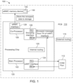
- FIG. 1 shows a schematic diagram of a BMC system 100 having an architecture for logging messages using a co-processor of the BMC system 100.
- the BMC system 100 manages operations, such as power management and thermal management for a server.
- the BMC system 100 effectively controls power supply and fan modules, according to data received from power and thermal sensors in the server.
- the BMC system 100 also receives operational data from, and provides settings to, various hardware components for the server.
- the BMC system 100 includes a printed circuit board (PCB) 110, a processing chip 120, and an embedded multimedia card (eMMC) memory device 130.
- PCB printed circuit board
- eMMC embedded multimedia card
- the processing chip 120 is a system-on-chip (SOC) that includes a built-in main processor 122 and a built-in co-processor 126 electrically connected to an external bus 112, called COM Port, embedded on the PCB 110.
- the processing chip 120 is configured to periodically monitor power data and other support for the electronic components of the BMC system 100 and the server, of which the BMC system 100 is a component of. In some embodiments, the monitoring rate of the processing chip 120 is dependent on the temperature and/or power data associated with the electronic components of the BMC system 100 and the server.
- the processing chip 120 may be manufactured by ASPEED Technology (e.g., AST2500), Nuvoton (e.g., NPCM730), or Texas Instruments (e.g., Sitara).
- the main processor 122 is coupled to a communication interface 124 having a receiver RX configured to receive an input from, and a transmitter TX configured to send an output to, a device or a bus such as, but not limited to, the external bus 112.
- the communication interface 124 is a Universal Asynchronous Receiver/Transmitter (UART) interface configured for host serial communication over Local Area Network (LAN) or debugging.
- UART Universal Asynchronous Receiver/Transmitter
- LAN Local Area Network
- one or more communication interfaces 124 each having a different communication protocol, may be used.
- the communication interfaces 124 may be a Universal Serial Bus (USB) interface, a General Purpose Input/Output (GPIO) interface, an Inter-Integrated Circuit (I2C) interface, a management console interface, and/or a debug interface.
- a GPIO interface may be used to control visual indicators such as LEDs that indicate BMC system heartbeat, BMC system health, Basic Input/Output System (BIOS) Power-On Self-Test (POST) code, power status, devices that are present (e.g., HDDs, SSDs, etc.) or any other statuses that the processing chip 120 can monitor.
- BIOS Basic Input/Output System
- POST Power-On Self-Test
- a management console interface may be used for BIOS firmware updates or debug logging storage.
- the main processor 122 is a relatively more powerful programmable control device than the co-processor 126.
- the co-processor 126 is communicatively coupled to the eMMC memory device 130, though any non-transitory processor-readable memory device may be used such as, but not limited to, a Serial Advanced Technology Attachment (SATA) device, a Serial Attached SCSI (SAS) device, a multimedia card (MMC), a Universal Serial Bus (USB) disk, a Peripheral Connect Interface express (PCIe) disk, a Serial Peripheral Interface (SPI) disk, an enhanced Serial Peripheral Interface (eSPI) disk, a Secure Digital Input Output (SDIO) card, and the like.
- SATA Serial Advanced Technology Attachment
- SAS Serial Attached SCSI
- MMC multimedia card
- USB Universal Serial Bus
- PCIe Peripheral Connect Interface express
- SPI Serial Peripheral Interface
- eSPI enhanced Serial Peripheral Interface
- SDIO Secure Digital Input Output
- the eMMC memory device 130 stores firmware that is executed by the co-processor 126 to perform various functions such as logging events, storing data and messages, etc.
- the eMMC memory device 130 includes a storage portion 135 for storing executable program code, data, and messages.
- the co-processor 126 is coupled to an eMMC interface 129 for connecting the co-processor 126 to the eMMC memory device 130.
- the co-processor 126 is also coupled to a snooping interface 128 having a receiver RX configured to receive an input from, and a transmitter TX configured to send an output to a device or a bus such as, but not limited to, the UART communication interface 124 or another communication interface 124.
- the snooping interface 128 is communicatively coupled to the UART communication interface 124 through an internal route 125 of programmable registers between the transmitter TX of the UART communication interface 124 and the receiver RX of the snooping interface 128 of the co-processor 126.
- the snooping interface 128 is communicatively coupled to the UART communication interface 124 through an external route 115 of traces on the PCB 110.
- FIG. 2 shows a flow diagram 200 demonstrating how the BMC system 100 logs messages using the co-processor 126.
- the BMC system 100 starts the process in step 205 and subsequently in step 210, the processing chip 120 is powered on.
- the BMC system 100 decides if the processing chip 120 can support powering on the co-processor 126 first.
- the main processor 122 If the processing chip 120 cannot support powering on the co-processor 126, the main processor 122 is powered on in step 222. The main processor 122 then triggers a power-on and boot-up of the co-processor 126 in step 224. Subsequently, at decision point 226, the main processor 122 decides if the co-processor 126 is ready for boot-up or in the alternative, waits until the co-processor 126 is ready for boot-up.
- the co-processor 126 is powered on and booted up before the main processor 122 is powered on, in step 230. Then, in step 240, the co-processor 126 both initiates the storage portion 135 of the eMMC memory device 130 and enables the snooping interface 128. This triggers the main processor 122 to power on and boot up, in step 250.
- step 252 the main processor 122 undergoes the booting process, including a boot-up event (u-boot), an operating system loading event (e.g., Linux kernel loading), a Random Access Memory (RAM) disk decompression event, and runtime services. Any booting messages, error messages, exception messages, and data generated during boot-up is then dumped or directed towards the UART communication interface 124, in step 254.
- u-boot boot-up event
- operating system loading event e.g., Linux kernel loading
- RAM Random Access Memory
- step 256 the main processor 122 moves on to an operational status in step 256, during which runtime services and daemons may be generated and executed. Any booting messages, error messages, exception messages, and data generated during operation of the main processor 122 is then dumped or directed towards the UART communication interface 124, in step 258.
- the booting messages, error messages, exception messages, and data generated during boot-up and operation of the main processor 122 in steps 254 and 258 are then redirected into the snooping interface 128.
- the co-processor 126 confirms receipt of the redirected messages and data from the UART communication interface 124 via the snooping interface 128. Subsequently, the co-processor 126 proceeds to store the redirected messages and data in the eMMC memory device 130 through the eMMC interface 129.
- the stored messages can be retrieved through the local area network (LAN) of the BMC system 100 or stored in a portable Secured Digital (SD) card.
- LAN local area network
- SD portable Secured Digital
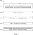
- FIG. 3 shows a block diagram of a method 300 of logging messages in a BMC system using a co-processor; for example, the co-processor 126 in the BMC system 100.
- the method 300 begins in block 310, where a processing chip of the BMC system is powered on.
- the processing chip includes a main processor and a co-processor.
- the co-processor is communicatively coupled to a non-transitory processor-readable memory device and a snooping interface.
- the method 300 then proceeds to block 320, where the co-processor is booted up.
- the co-processor is further configured to boot up before the main processor is powered on, if the co-processor is powered-on before the main processor.
- the main processor is configured to trigger a boot-up of the co-processor, if the main processor is powered on before the co- processor.
- the non-transitory processor-readable memory device may be an electronic multimedia card (eMMC), a Serial Advanced Technology Attachment (SATA) device, a Serial Attached SCSI (SAS) device, a multimedia card (MMC), a Universal Serial Bus (USB) disk, a Peripheral Connect Interface express (PCIe) disk, a Serial Peripheral Interface (SPI) disk, an enhanced Serial Peripheral Interface (eSPI) disk, a Secure Digital Input Output (SDIO) card, and the like.
- eMMC electronic multimedia card
- SATA Serial Advanced Technology Attachment
- SAS Serial Attached SCSI
- MMC multimedia card
- USB Universal Serial Bus
- PCIe Peripheral Connect Interface express
- SPI Serial Peripheral Interface
- eSPI enhanced Serial Peripheral Interface
- SDIO Secure Digital Input Output
- the method 300 proceeds to receive messages redirected from a communication interface of the BMC system via the snooping interface.
- the communication interface may be a Universal Asynchronous Receiver/Transmitter (UART) interface, a Universal Serial Bus (USB) interface, a General Purpose Input/Output (GPIO) interface, an Inter-Integrated Circuit (I2C) interface, a management console interface, and/or a debug interface.
- UART Universal Asynchronous Receiver/Transmitter
- USB Universal Serial Bus
- GPIO General Purpose Input/Output
- I2C Inter-Integrated Circuit
- the messages comprise booting messages, error messages, and exception messages generated during boot-up and operation of the main processor.
- the booting messages are associated with a boot-up event (u-boot), an operating system loading event (e.g., Linux kernel loading), a RAM disk decompression event, and runtime services of the main processor.
- the method further includes saving the received messages in the non-transitory processor-readable memory device for future use and analysis.
- the method further includes routing the redirected messages externally through traces of a printed circuit board (PCB) on which the BMC system is embedded. In other embodiments, the method further includes routing the redirected messages internally within the processing chip, wherein registers between a transmitter of the communication interface and a receiver of the snooping interface are programmed for the routing.
- PCB printed circuit board
- the systems and methods of logging messages using a co-processor of the BMC can benefit both the developer and the end-user of the server by retrieving booting messages, error messages, exception messages, and data related to potential system issues like sudden hang-up of the processing chip in the BMC system, inability of the BMC system to boot up properly, network disconnection of the BMC system, reboot of the watchdog timeout of the BMC system, etc. Error and/or exception messages with any of these or similar issues are sent to a communication interface of the BMC system, but cannot be otherwise retrieved, if the BMC system is not fully functional. Therefore, the systems and methods described herein use the existing co-processor in the processing chip of the BMC system to monitor, store, and analyze messages during boot-up and operation of BMC system, without incurring cost of additional devices for intercepting messages from the communication system.
Landscapes
- Engineering & Computer Science (AREA)
- Theoretical Computer Science (AREA)
- Physics & Mathematics (AREA)
- General Engineering & Computer Science (AREA)
- General Physics & Mathematics (AREA)
- Software Systems (AREA)
- Quality & Reliability (AREA)
- Computer Security & Cryptography (AREA)
- Computer Hardware Design (AREA)
- Computing Systems (AREA)
- Computer Networks & Wireless Communication (AREA)
- Mathematical Physics (AREA)
- Debugging And Monitoring (AREA)
- Stored Programmes (AREA)
Abstract
Embodiments of this disclosure are directed towards a method of logging messages in a baseboard management controller (BMC) system. The method includes powering on a processing chip of the BMC system, wherein the processing chip has a main processor and a co-processor that is communicatively coupled to a non-transitory processor-readable memory device and snooping interface. The method further includes booting up the co-processor, and initiating a storage portion of the non-transitory processor-readable memory device the snooping interface. The method further includes triggering a boot-up of the main processor, and receiving, via the snooping interface, the messages redirected from a communication interface of the BMC system.
Description
- The present invention relates generally to a baseboard management controller (BMC) used in servers, and more specifically, to systems and methods of logging messages using a co-processor of the BMC.
- Servers are employed in large numbers for high demand applications, such as network-based systems or data centers. The emergence of cloud computing applications has increased the demand for data centers. Each server generally includes hardware components such as processors, memory devices, network interface cards, power supplies, and other specialized hardware. Servers generally include a baseboard management controller (BMC) that manages the operation of hardware components as well as support components, such as power supplies and fans. The BMC also communicates operational data to a central management station that manages the servers of the rack. The BMC relieves the need for the Central Processing Unit (CPU) of the server to monitor server operations. It is thus desirable to keep and track a log of messages and events that occur during boot-up and operation of the BMC.
- The term embodiment and like terms, e.g., implementation, configuration, aspect, example, and option, are intended to refer broadly to all of the subject matter of this disclosure and the claims below. Statements containing these terms should be understood not to limit the subject matter described herein or to limit the meaning or scope of the claims below. Embodiments of the present disclosure covered herein are defined by the claims below, not this summary. This summary is a high-level overview of various aspects of the disclosure and introduces some of the concepts that are further described in the Detailed Description section below. This summary is not intended to identify key or essential features of the claimed subject matter. This summary is also not intended to be used in isolation to determine the scope of the claimed subject matter. The subject matter should be understood by reference to appropriate portions of the entire specification of this disclosure, any or all drawings, and each claim.
- According to certain aspects of the present disclosure, a method of logging messages in a baseboard management controller (BMC) system includes powering on a processing chip of the BMC system, wherein the processing chip has a main processor and a co-processor that is communicatively coupled to a non-transitory processor-readable memory device and snooping interface. The method further includes booting up the co-processor, and initiating a storage portion of the non-transitory processor-readable memory device the snooping interface. The method further includes triggering a boot-up of the main processor, and receiving, via the snooping interface, the messages redirected from a communication interface of the BMC system.
- According to certain aspects of the present disclosure, the method further includes saving the received messages in the non-transitory processor-readable memory device.
- According to certain aspects of the present disclosure, the method step of booting up the co-processor is performed before the main processor is powered on, if the co-processor is powered on before the main processor.
- According to certain aspects of the present disclosure, the method step of booting up the co-processor is performed by triggering a boot-up of the co-processor by the main processor, if the main processor is powered on before the co-processor.
- According to certain aspects of the present disclosure, the method further includes routing the redirected messages externally through traces of a printed circuit board (PCB) on which the BMC system is embedded.
- According to certain aspects of the present disclosure, the method further includes routing the redirected messages internally within the processing chip, the routing including programming registers between a transmitter of the communication interface and a receiver of the snooping interface.
- According to certain aspects of the present disclosure, a baseboard management controller (BMC) system is disclosed. The BMC system includes a processing chip having a built-in main processor and a built-in co-processor, at least one communication interface communicatively coupled to the main processor, at least one snooping interface coupled to the co-processor, and a non-transitory processor-readable memory device communicatively coupled to the co-processor. The memory device includes a storage portion. The memory device has machine-readable instructions saved thereon, which when executed, configure the co-processor to perform a method of logging messages. The method includes powering on a processing chip of the BMC system, booting up the co-processor, and initiating the storage portion and the at least one snooping interface. The method further includes triggering a boot-up of the main processor, and receiving the messages redirected from the at least one communication interface of the BMC system via the at least one snooping interface.
- According to certain aspects of the present disclosure, the co-processor is further configured to save the received messages in the non-transitory processor-readable memory device.
- According to certain aspects of the present disclosure, the at least one communication interface is a Universal Asynchronous Receiver/Transmitter (UART) interface, a Universal Serial Bus interface, a General Purpose Input/Output (GPIO) interface, an Inter-Integrated Circuit (I2C) interface, a management console interface, or a debug interface.
- According to certain aspects of the present disclosure, the co-processor is further configured to boot up before the main processor is powered on, if the co-processor is powered on before the main processor.
- According to certain aspects of the present disclosure, the main processor is configured to trigger a boot-up of the co-processor, if the main processor is powered on before the co-processor
- According to certain aspects of the present disclosure, the received messages include booting messages, error messages, and exception messages generated during boot-up and operation of the main processor.
- According to certain aspects of the present disclosure, the booting messages are associated with (i) a boot-up event, (ii) an operating system loading event, (iii) a Random Access Memory (RAM) disk decompression event, and (iv) runtime services of the main processor.
- According to certain aspects of the present disclosure, the BMC system further includes traces on a printed circuit board (PCB) on which the processing chip is embedded, wherein the traces are configured to route the redirected messages external to the processing chip.
- According to certain aspects of the present disclosure, the processing chip further includes registers between a transmitter of the at least one communication interface of the main processor and a receiver of the at least one snooping interface of the co-processor, wherein the registers are programmed to route the redirected messages internally within the processing chip.
- According to certain aspects of the present disclosure, the non-transitory processor-readable memory device communicatively coupled to the co-processor is an electronic multimedia card (eMMC), a Serial Advanced Technology Attachment (SATA) device, a Serial Attached SCSI (SAS) device, a multimedia card (MMC), a Universal Serial Bus (USB) disk, a Peripheral Connect Interface express (PCIe) disk, a Serial Peripheral Interface (SPI) disk, an enhanced Serial Peripheral Interface (eSPI) disk, or a Secure Digital Input Output (SDIO) card.
- The above summary is not intended to represent each embodiment or every aspect of the present disclosure. Rather, the foregoing summary merely provides an example of some of the novel aspects and features set forth herein. The above features and advantages, and other features and advantages of the present disclosure, will be readily apparent from the following detailed description of representative embodiments and modes for carrying out the present invention, when taken in connection with the accompanying drawings and the appended claims. Additional aspects of the disclosure will be apparent to those of ordinary skill in the art in view of the detailed description of various embodiments, which is made with reference to the drawings, a brief description of which is provided below.
- The disclosure, and its advantages and drawings, will be better understood from the following description of representative embodiments together with reference to the accompanying drawings. These drawings depict only representative embodiments, and are therefore not to be considered as limitations on the scope of the various embodiments or claims.
-
FIG. 1 shows a schematic diagram of a BMC system having an architecture for logging messages using a co-processor of the BMC system, according to certain aspects of the present disclosure. -
FIG. 2 shows a flow diagram demonstrating how the BMC system ofFIG. 1 logs messages using the co-processor, according to certain aspects of the present disclosure. -
FIG. 3 shows a block diagram of a method of logging messaging in a BMC system using a co-processor, according to certain aspects of the present disclosure. - The present disclosure is susceptible to various modifications and alternative forms, and some representative embodiments have been shown by way of example in the drawings and will be described in detail herein. It should be understood, however, that the invention is not intended to be limited to the particular forms disclosed. Rather, the disclosure is to cover all modifications, equivalents, and alternatives falling within the scope of the invention as defined by the appended claims.
- Embodiments of the disclosure are directed to BMC systems and methods of logging messages using a co-processor of the BMC. The co-processor boots up before a main processor in a processing chip of the BMC system, and booting messages, error messages, and exception messages generated during boot-up and operation of the main processor are redirected from a communication interface of the BMC system via a snooping interface into the co-processor. The messages are then saved in a memory device that is communicatively coupled to the co-processor for future use and analysis. Further details on the implementations are described below.
- Various embodiments are described with reference to the attached figures, where like reference numerals are used throughout the figures to designate similar or equivalent elements. The figures are not necessarily drawn to scale and are provided merely to illustrate aspects and features of the present disclosure. Numerous specific details, relationships, and methods are set forth to provide a full understanding of certain aspects and features of the present disclosure, although one having ordinary skill in the relevant art will recognize that these aspects and features can be practiced without one or more of the specific details, with other relationships, or with other methods. In some instances, well-known structures or operations are not shown in detail for illustrative purposes. The various embodiments disclosed herein are not necessarily limited by the illustrated ordering of acts or events, as some acts may occur in different orders and/or concurrently with other acts or events. Furthermore, not all illustrated acts or events are necessarily required to implement certain aspects and features of the present disclosure.
- For purposes of the present detailed description, unless specifically disclaimed, and where appropriate, the singular includes the plural and vice versa. The word "including" means "including without limitation." Moreover, words of approximation, such as "about," "almost," "substantially," "approximately," and the like, can be used herein to mean "at," "near," "nearly at," "within 3-5% of," "within acceptable manufacturing tolerances of," or any logical combination thereof. Similarly, terms "vertical" or "horizontal" are intended to additionally include "within 3-5% of' a vertical or horizontal orientation, respectively. Additionally, words of direction, such as "top," "bottom," "left," "right," "above," and "below" are intended to relate to the equivalent direction as depicted in a reference illustration; as understood contextually from the object(s) or element(s) being referenced, such as from a commonly used position for the object(s) or element(s); or as otherwise described herein.
-
FIG. 1 shows a schematic diagram of aBMC system 100 having an architecture for logging messages using a co-processor of theBMC system 100. TheBMC system 100 manages operations, such as power management and thermal management for a server. TheBMC system 100 effectively controls power supply and fan modules, according to data received from power and thermal sensors in the server. TheBMC system 100 also receives operational data from, and provides settings to, various hardware components for the server. In the non-limiting embodiment shown inFIG. 1 , theBMC system 100 includes a printed circuit board (PCB) 110, aprocessing chip 120, and an embedded multimedia card (eMMC)memory device 130. - The
processing chip 120 is a system-on-chip (SOC) that includes a built-inmain processor 122 and a built-inco-processor 126 electrically connected to anexternal bus 112, called COM Port, embedded on thePCB 110. Theprocessing chip 120 is configured to periodically monitor power data and other support for the electronic components of theBMC system 100 and the server, of which theBMC system 100 is a component of. In some embodiments, the monitoring rate of theprocessing chip 120 is dependent on the temperature and/or power data associated with the electronic components of theBMC system 100 and the server. In some embodiments, theprocessing chip 120 may be manufactured by ASPEED Technology (e.g., AST2500), Nuvoton (e.g., NPCM730), or Texas Instruments (e.g., Sitara). - The
main processor 122 is coupled to acommunication interface 124 having a receiver RX configured to receive an input from, and a transmitter TX configured to send an output to, a device or a bus such as, but not limited to, theexternal bus 112. In the non-limiting example shown inFIG. 1 , thecommunication interface 124 is a Universal Asynchronous Receiver/Transmitter (UART) interface configured for host serial communication over Local Area Network (LAN) or debugging. However, in other embodiments, one ormore communication interfaces 124, each having a different communication protocol, may be used. The communication interfaces 124 may be a Universal Serial Bus (USB) interface, a General Purpose Input/Output (GPIO) interface, an Inter-Integrated Circuit (I2C) interface, a management console interface, and/or a debug interface. As a non-limiting example, a GPIO interface may be used to control visual indicators such as LEDs that indicate BMC system heartbeat, BMC system health, Basic Input/Output System (BIOS) Power-On Self-Test (POST) code, power status, devices that are present (e.g., HDDs, SSDs, etc.) or any other statuses that theprocessing chip 120 can monitor. As another non-limiting example, a management console interface may be used for BIOS firmware updates or debug logging storage. Themain processor 122 is a relatively more powerful programmable control device than theco-processor 126. - The
co-processor 126 is communicatively coupled to theeMMC memory device 130, though any non-transitory processor-readable memory device may be used such as, but not limited to, a Serial Advanced Technology Attachment (SATA) device, a Serial Attached SCSI (SAS) device, a multimedia card (MMC), a Universal Serial Bus (USB) disk, a Peripheral Connect Interface express (PCIe) disk, a Serial Peripheral Interface (SPI) disk, an enhanced Serial Peripheral Interface (eSPI) disk, a Secure Digital Input Output (SDIO) card, and the like. TheeMMC memory device 130 stores firmware that is executed by the co-processor 126 to perform various functions such as logging events, storing data and messages, etc. TheeMMC memory device 130 includes astorage portion 135 for storing executable program code, data, and messages. Theco-processor 126 is coupled to aneMMC interface 129 for connecting the co-processor 126 to theeMMC memory device 130. - The
co-processor 126 is also coupled to a snoopinginterface 128 having a receiver RX configured to receive an input from, and a transmitter TX configured to send an output to a device or a bus such as, but not limited to, theUART communication interface 124 or anothercommunication interface 124. In some embodiments, the snoopinginterface 128 is communicatively coupled to theUART communication interface 124 through aninternal route 125 of programmable registers between the transmitter TX of theUART communication interface 124 and the receiver RX of the snoopinginterface 128 of theco-processor 126. In other embodiments, the snoopinginterface 128 is communicatively coupled to theUART communication interface 124 through anexternal route 115 of traces on thePCB 110. -
FIG. 2 shows a flow diagram 200 demonstrating how theBMC system 100 logs messages using theco-processor 126. TheBMC system 100 starts the process instep 205 and subsequently instep 210, theprocessing chip 120 is powered on. Atdecision point 220, theBMC system 100 decides if theprocessing chip 120 can support powering on the co-processor 126 first. - If the
processing chip 120 cannot support powering on theco-processor 126, themain processor 122 is powered on instep 222. Themain processor 122 then triggers a power-on and boot-up of the co-processor 126 instep 224. Subsequently, atdecision point 226, themain processor 122 decides if theco-processor 126 is ready for boot-up or in the alternative, waits until theco-processor 126 is ready for boot-up. - On the other hand, if the
processing chip 120 can support powering on theco-processor 126, theco-processor 126 is powered on and booted up before themain processor 122 is powered on, instep 230. Then, instep 240, the co-processor 126 both initiates thestorage portion 135 of theeMMC memory device 130 and enables the snoopinginterface 128. This triggers themain processor 122 to power on and boot up, instep 250. - In
step 252, themain processor 122 undergoes the booting process, including a boot-up event (u-boot), an operating system loading event (e.g., Linux kernel loading), a Random Access Memory (RAM) disk decompression event, and runtime services. Any booting messages, error messages, exception messages, and data generated during boot-up is then dumped or directed towards theUART communication interface 124, instep 254. - Similarly, once the
main processor 122 has booted up, themain processor 122 moves on to an operational status instep 256, during which runtime services and daemons may be generated and executed. Any booting messages, error messages, exception messages, and data generated during operation of themain processor 122 is then dumped or directed towards theUART communication interface 124, instep 258. - The booting messages, error messages, exception messages, and data generated during boot-up and operation of the
main processor 122 insteps interface 128. Atdecision point 260, theco-processor 126 confirms receipt of the redirected messages and data from theUART communication interface 124 via the snoopinginterface 128. Subsequently, the co-processor 126 proceeds to store the redirected messages and data in theeMMC memory device 130 through theeMMC interface 129. The stored messages can be retrieved through the local area network (LAN) of theBMC system 100 or stored in a portable Secured Digital (SD) card. -
FIG. 3 shows a block diagram of amethod 300 of logging messages in a BMC system using a co-processor; for example, the co-processor 126 in theBMC system 100. Themethod 300 begins inblock 310, where a processing chip of the BMC system is powered on. The processing chip includes a main processor and a co-processor. The co-processor is communicatively coupled to a non-transitory processor-readable memory device and a snooping interface. Themethod 300 then proceeds to block 320, where the co-processor is booted up. In some embodiments, the co-processor is further configured to boot up before the main processor is powered on, if the co-processor is powered-on before the main processor. In other embodiments, the main processor is configured to trigger a boot-up of the co-processor, if the main processor is powered on before the co- processor. - In
block 330, after the co-processor is booted, a storage portion of the non-transitory processor-readable memory device and the snooping interface are initiated. In some embodiments, the non-transitory processor-readable memory device may be an electronic multimedia card (eMMC), a Serial Advanced Technology Attachment (SATA) device, a Serial Attached SCSI (SAS) device, a multimedia card (MMC), a Universal Serial Bus (USB) disk, a Peripheral Connect Interface express (PCIe) disk, a Serial Peripheral Interface (SPI) disk, an enhanced Serial Peripheral Interface (eSPI) disk, a Secure Digital Input Output (SDIO) card, and the like. Inblock 340, a boot-up of the main processor is triggered by the BMC system. - In
block 350, themethod 300 proceeds to receive messages redirected from a communication interface of the BMC system via the snooping interface. In some embodiments, the communication interface may be a Universal Asynchronous Receiver/Transmitter (UART) interface, a Universal Serial Bus (USB) interface, a General Purpose Input/Output (GPIO) interface, an Inter-Integrated Circuit (I2C) interface, a management console interface, and/or a debug interface. - In some embodiments, the messages comprise booting messages, error messages, and exception messages generated during boot-up and operation of the main processor. In some embodiments, the booting messages are associated with a boot-up event (u-boot), an operating system loading event (e.g., Linux kernel loading), a RAM disk decompression event, and runtime services of the main processor. In some embodiments, the method further includes saving the received messages in the non-transitory processor-readable memory device for future use and analysis.
- In some embodiments, the method further includes routing the redirected messages externally through traces of a printed circuit board (PCB) on which the BMC system is embedded. In other embodiments, the method further includes routing the redirected messages internally within the processing chip, wherein registers between a transmitter of the communication interface and a receiver of the snooping interface are programmed for the routing.
- Advantageously, the systems and methods of logging messages using a co-processor of the BMC, as described herein, can benefit both the developer and the end-user of the server by retrieving booting messages, error messages, exception messages, and data related to potential system issues like sudden hang-up of the processing chip in the BMC system, inability of the BMC system to boot up properly, network disconnection of the BMC system, reboot of the watchdog timeout of the BMC system, etc. Error and/or exception messages with any of these or similar issues are sent to a communication interface of the BMC system, but cannot be otherwise retrieved, if the BMC system is not fully functional. Therefore, the systems and methods described herein use the existing co-processor in the processing chip of the BMC system to monitor, store, and analyze messages during boot-up and operation of BMC system, without incurring cost of additional devices for intercepting messages from the communication system.
- Although the disclosed embodiments have been illustrated and described with respect to one or more implementations, equivalent alterations and modifications will occur or be known to others skilled in the art upon the reading and understanding of this specification and the annexed drawings. In addition, while a particular feature of the invention may have been disclosed with respect to only one of several implementations, such feature may be combined with one or more other features of the other implementations as may be desired and advantageous for any given or particular application.
- While various embodiments of the present disclosure have been described above, it should be understood that they have been presented by way of example only, and not limitation. Numerous changes to the disclosed embodiments can be made in accordance with the disclosure herein, without departing from the scope of the disclosure. Thus, the breadth and scope of the present disclosure should not be limited by any of the above described embodiments. Rather, the scope of the disclosure should be defined in accordance with the following claims and their equivalents.
Claims (15)
- A method of logging messages in a baseboard management controller (BMC) system, the method comprising:powering on a processing chip of the BMC system, the processing chip having a main processor and a co-processor, the co-processor communicatively coupled to a non-transitory processor-readable memory device and a snooping interface;booting up the co-processor;initiating a storage portion of the non-transitory processor-readable memory device and the snooping interface;triggering a boot-up of the main processor; andreceiving, via the snooping interface, the messages redirected from a communication interface of the BMC system.
- The method of the previous claim, further comprising saving the received messages in the non-transitory processor-readable memory device.
- The method of any of the previous claim, wherein the communication interface is one of: a Universal Asynchronous Receiver/Transmitter (UART) interface, a Universal Serial Bus interface, a General Purpose Input/Output (GPIO) interface, an Inter-Integrated Circuit (I2C) interface, a management console interface, or a debug interface.
- The method of any of the previous claims, wherein the booting up the co-processor is performed before the main processor is powered on, if the co-processor is powered on before the main processor, and/or wherein the booting up the co-processor is performed by triggering a boot-up of the co-processor by the main processor, if the main processor is powered on before the co-processor.
- The method of any of the previous claims, wherein the received messages comprise booting messages, error messages, and exception messages generated during boot-up and operation of the main processor.
- The method of the previous claim, wherein the booting messages are associated with (i) a boot-up event, (ii) an operating system loading event, (iii) a RAM disk decompression event, and (iv) runtime services of the main processor.
- The method of any of the previous claims, further comprising routing the redirected messages externally through traces of a printed circuit board (PCB) on which the BMC system is embedded, and/or further comprising routing the redirected messages internally within the processing chip, the routing including programming registers between a transmitter of the communication interface and a receiver of the snooping interface.
- The method of any of the previous claims, wherein the non-transitory processor-readable memory device communicatively coupled to the co-processor is one of: an electronic multimedia card (eMMC), a Serial Advanced Technology Attachment (SATA) device, a Serial Attached SCSI (SAS) device, a multimedia card (MMC), a Universal Serial Bus (USB) disk, a Peripheral Connect Interface express (PCIe) disk, a Serial Peripheral Interface (SPI) disk, an enhanced Serial Peripheral Interface (eSPI) disk, or a Secure Digital Input Output (SDIO) card.
- A baseboard management controller (BMC) system, comprising:a processing chip including a built-in main processor and a built-in co-processor;at least one communication interface communicatively coupled to the main processor;at least one snooping interface coupled to the co-processor; anda non-transitory processor-readable memory device communicatively coupled to the co-processor and having a storage portion, the memory device having machine-readable instructions saved thereon, which when executed configure the co-processor to:power on the processing chip;boot up the co-processor;initiate the storage portion and the at least one snooping interface;trigger a boot-up of the main processor; andreceive messages redirected from the at least one communication interface via the at least one snooping interface.
- The BMC system of the previous system claim, wherein the co-processor is further configured to save the received messages in the non-transitory processor-readable memory device, and/or wherein the at least one communication interface is one of: a Universal Asynchronous Receiver/Transmitter (UART) interface, a Universal Serial Bus interface, a General Purpose Input/Output (GPIO) interface, an Inter-Integrated Circuit (I2C) interface, a management console interface, or a debug interface.
- The BMC system of any of the previous system claims, wherein the co-processor is further configured to boot up before the main processor is powered on, if the co-processor is powered on before the main processor, and/or wherein the main processor is configured to trigger a boot-up of the co-processor, if the main processor is powered on before the co-processor.
- The BMC system of any of the previous system claims, wherein received messages comprise booting messages, error messages, and exception messages generated during boot-up and operation of the main processor.
- The BMC system of the previous claim, wherein the booting messages are associated with (i) a boot-up event, (ii) an operating system loading event, (iii) a RAM disk decompression event, and (iv) runtime services of the main processor.
- The BMC system of any of the previous system claims, further comprising traces on a printed circuit board (PCB) on which the processing chip is embedded, wherein the traces are configured to route the redirected messages external to the processing chip.
- The BMC system of any of the previous system claims, wherein the processing chip further comprises registers between a transmitter of the at least one communication interface and a receiver of the at least one snooping interface, the registers being programmed to route the redirected messages internally within the processing chip, and/or wherein the non-transitory processor-readable memory device communicatively coupled to the co-processor is one of: an electronic multimedia card (eMMC), a Serial Advanced Technology Attachment (SATA) device, a Serial Attached SCSI (SAS) device, a multimedia card (MMC), a Universal Serial Bus (USB) disk, a Peripheral Connect Interface express (PCIe) disk, a Serial Peripheral Interface (SPI) disk, an enhanced Serial Peripheral Interface (eSPI) disk, or a Secure Digital Input Output (SDIO) card.
Applications Claiming Priority (1)
| Application Number | Priority Date | Filing Date | Title |
|---|---|---|---|
| US17/534,717 US11775372B2 (en) | 2021-11-24 | 2021-11-24 | Logging messages in a baseboard management controller using a co-processor |
Publications (1)
| Publication Number | Publication Date |
|---|---|
| EP4187375A1 true EP4187375A1 (en) | 2023-05-31 |
Family
ID=81346309
Family Applications (1)
| Application Number | Title | Priority Date | Filing Date |
|---|---|---|---|
| EP22165880.0A Withdrawn EP4187375A1 (en) | 2021-11-24 | 2022-03-31 | Logging messages in a baseboard management controller using a co-processor |
Country Status (5)
| Country | Link |
|---|---|
| US (1) | US11775372B2 (en) |
| EP (1) | EP4187375A1 (en) |
| JP (1) | JP7324906B2 (en) |
| CN (1) | CN116166493B (en) |
| TW (1) | TWI809773B (en) |
Families Citing this family (3)
| Publication number | Priority date | Publication date | Assignee | Title |
|---|---|---|---|---|
| CN117806857B (en) * | 2023-07-28 | 2024-05-14 | 苏州浪潮智能科技有限公司 | Fault location information generation method, device, electronic device and storage medium |
| US12608322B2 (en) * | 2023-09-19 | 2026-04-21 | American Megatrends International, Llc | Techniques of encrypting BMC and bios firmware and data in flash memory |
| US20260050446A1 (en) * | 2024-08-16 | 2026-02-19 | Hewlett Packard Enterprise Development Lp | Platform agnostic boot system |
Citations (1)
| Publication number | Priority date | Publication date | Assignee | Title |
|---|---|---|---|---|
| US20130117803A1 (en) * | 2011-11-04 | 2013-05-09 | Honeywell International Inc. | Security and safety manager implementation in a multi-core processor |
Family Cites Families (10)
| Publication number | Priority date | Publication date | Assignee | Title |
|---|---|---|---|---|
| TW200725278A (en) | 2005-12-29 | 2007-07-01 | Inventec Corp | Method and system for controlling information exchange between power management unit and boot control unit |
| JP2007265157A (en) | 2006-03-29 | 2007-10-11 | Nec Corp | System and method for detecting fault of i/o device |
| JP2008176682A (en) | 2007-01-22 | 2008-07-31 | Renesas Technology Corp | Semiconductor integrated circuit and data processing system |
| TW201314576A (en) | 2011-09-27 | 2013-04-01 | Acer Inc | Method for accessing pre-boot information |
| JP2013088394A (en) | 2011-10-21 | 2013-05-13 | Renesas Electronics Corp | Semiconductor device |
| US9712382B2 (en) | 2014-10-27 | 2017-07-18 | Quanta Computer Inc. | Retrieving console messages after device failure |
| US9954727B2 (en) | 2015-03-06 | 2018-04-24 | Quanta Computer Inc. | Automatic debug information collection |
| US20180213669A1 (en) | 2015-07-10 | 2018-07-26 | Prasad Lalathuputhanpura KOCHUKUNJU | Micro data center (mdc) in a box system and method thereof |
| US9678682B2 (en) * | 2015-10-13 | 2017-06-13 | International Business Machines Corporation | Backup storage of vital debug information |
| US11550664B2 (en) * | 2019-04-08 | 2023-01-10 | Dell Products L.P. | Early boot event logging system |
-
2021
- 2021-11-24 US US17/534,717 patent/US11775372B2/en active Active
-
2022
- 2022-03-23 TW TW111110777A patent/TWI809773B/en active
- 2022-03-31 EP EP22165880.0A patent/EP4187375A1/en not_active Withdrawn
- 2022-04-12 CN CN202210381392.5A patent/CN116166493B/en active Active
- 2022-06-22 JP JP2022100057A patent/JP7324906B2/en active Active
Patent Citations (1)
| Publication number | Priority date | Publication date | Assignee | Title |
|---|---|---|---|---|
| US20130117803A1 (en) * | 2011-11-04 | 2013-05-09 | Honeywell International Inc. | Security and safety manager implementation in a multi-core processor |
Non-Patent Citations (2)
| Title |
|---|
| ANONYMOUS: "Event monitoring - Wikipedia", 29 November 2018 (2018-11-29), pages 1 - 2, XP093023622, Retrieved from the Internet <URL:https://en.wikipedia.org/w/index.php?title=Event_monitoring&oldid=871191379> [retrieved on 20230214] * |
| XIAOLAN ZHANG ET AL: "Secure coprocessor-based intrusion detection", ACM SIGOPS EUROPEAN WORKSHOP, ACM, 2 PENN PLAZA, SUITE 701 NEW YORK NY 10121-0701 USA, 1 July 2002 (2002-07-01), pages 239 - 242, XP058273960, DOI: 10.1145/1133373.1133423 * |
Also Published As
| Publication number | Publication date |
|---|---|
| US11775372B2 (en) | 2023-10-03 |
| CN116166493A (en) | 2023-05-26 |
| JP7324906B2 (en) | 2023-08-10 |
| CN116166493B (en) | 2026-02-27 |
| JP2023077376A (en) | 2023-06-05 |
| TWI809773B (en) | 2023-07-21 |
| TW202321911A (en) | 2023-06-01 |
| US20230161658A1 (en) | 2023-05-25 |
Similar Documents
| Publication | Publication Date | Title |
|---|---|---|
| US11775372B2 (en) | Logging messages in a baseboard management controller using a co-processor | |
| EP3871080B1 (en) | System and method to recover fpga firmware over a sideband interface | |
| EP3211532B1 (en) | Warm swapping of hardware components with compatibility verification | |
| US10102170B2 (en) | System and method for providing input/output functionality by an I/O complex switch | |
| US10855739B2 (en) | Video redirection across multiple information handling systems (IHSs) using a graphics core and a bus bridge integrated into an enclosure controller (EC) | |
| US10846159B2 (en) | System and method for managing, resetting and diagnosing failures of a device management bus | |
| US20060020845A1 (en) | Unattended BIOS recovery | |
| US10606784B1 (en) | Software filtering of redundant sideband device management bus communications | |
| US11308002B2 (en) | Systems and methods for detecting expected user intervention across multiple blades during a keyboard, video, and mouse (KVM) session | |
| US10783109B2 (en) | Device management messaging protocol proxy | |
| US9880858B2 (en) | Systems and methods for reducing BIOS reboots | |
| US20200104140A1 (en) | Systems and methods for identifying and protection of boot storage devices | |
| US10853204B2 (en) | System and method to detect and recover from inoperable device management bus | |
| US10852792B2 (en) | System and method for recovery of sideband interfaces for controllers | |
| US11334359B2 (en) | Systems and methods for management of dynamic devices | |
| US20240362131A1 (en) | Systems and methods for configuration of witness sleds | |
| US20240103830A1 (en) | Systems and methods for personality based firmware updates | |
| US20230205549A1 (en) | Virtual controller in a multi-node system | |
| CN115098342A (en) | System log collection method, system, terminal and storage medium | |
| US11755334B2 (en) | Systems and methods for augmented notifications in remote management of an IHS (information handling system) | |
| US12632558B2 (en) | Securing legacy adapters with a secure microcontroller unit and legacy adapter recovery | |
| US20250328647A1 (en) | Securing legacy adapters with a secure microcontroller unit and legacy adapter recovery | |
| US20240248728A1 (en) | Customized fit image descriptors for resources stored over the network |
Legal Events
| Date | Code | Title | Description |
|---|---|---|---|
| PUAI | Public reference made under article 153(3) epc to a published international application that has entered the european phase |
Free format text: ORIGINAL CODE: 0009012 |
|
| STAA | Information on the status of an ep patent application or granted ep patent |
Free format text: STATUS: EXAMINATION IS IN PROGRESS |
|
| 17P | Request for examination filed |
Effective date: 20221129 |
|
| AK | Designated contracting states |
Kind code of ref document: A1 Designated state(s): AL AT BE BG CH CY CZ DE DK EE ES FI FR GB GR HR HU IE IS IT LI LT LU LV MC MK MT NL NO PL PT RO RS SE SI SK SM TR |
|
| STAA | Information on the status of an ep patent application or granted ep patent |
Free format text: STATUS: THE APPLICATION IS DEEMED TO BE WITHDRAWN |
|
| 18D | Application deemed to be withdrawn |
Effective date: 20240319 |