EP4187325A1 - Heating device and image forming apparatus - Google Patents
Heating device and image forming apparatus Download PDFInfo
- Publication number
- EP4187325A1 EP4187325A1 EP22208515.1A EP22208515A EP4187325A1 EP 4187325 A1 EP4187325 A1 EP 4187325A1 EP 22208515 A EP22208515 A EP 22208515A EP 4187325 A1 EP4187325 A1 EP 4187325A1
- Authority
- EP
- European Patent Office
- Prior art keywords
- heater
- heating device
- end side
- thermostat
- electric wire
- Prior art date
- Legal status (The legal status is an assumption and is not a legal conclusion. Google has not performed a legal analysis and makes no representation as to the accuracy of the status listed.)
- Pending
Links
Images






Classifications
-
- G—PHYSICS
- G03—PHOTOGRAPHY; CINEMATOGRAPHY; ANALOGOUS TECHNIQUES USING WAVES OTHER THAN OPTICAL WAVES; ELECTROGRAPHY; HOLOGRAPHY
- G03G—ELECTROGRAPHY; ELECTROPHOTOGRAPHY; MAGNETOGRAPHY
- G03G15/00—Apparatus for electrographic processes using a charge pattern
- G03G15/20—Apparatus for electrographic processes using a charge pattern for fixing, e.g. by using heat
- G03G15/2003—Apparatus for electrographic processes using a charge pattern for fixing, e.g. by using heat using heat
- G03G15/2014—Apparatus for electrographic processes using a charge pattern for fixing, e.g. by using heat using heat using contact heat
- G03G15/2017—Structural details of the fixing unit in general, e.g. cooling means, heat shielding means
-
- G—PHYSICS
- G03—PHOTOGRAPHY; CINEMATOGRAPHY; ANALOGOUS TECHNIQUES USING WAVES OTHER THAN OPTICAL WAVES; ELECTROGRAPHY; HOLOGRAPHY
- G03G—ELECTROGRAPHY; ELECTROPHOTOGRAPHY; MAGNETOGRAPHY
- G03G15/00—Apparatus for electrographic processes using a charge pattern
- G03G15/20—Apparatus for electrographic processes using a charge pattern for fixing, e.g. by using heat
- G03G15/2003—Apparatus for electrographic processes using a charge pattern for fixing, e.g. by using heat using heat
- G03G15/2014—Apparatus for electrographic processes using a charge pattern for fixing, e.g. by using heat using heat using contact heat
- G03G15/2039—Apparatus for electrographic processes using a charge pattern for fixing, e.g. by using heat using heat using contact heat with means for controlling the fixing temperature
- G03G15/2046—Apparatus for electrographic processes using a charge pattern for fixing, e.g. by using heat using heat using contact heat with means for controlling the fixing temperature specially for the influence of heat loss, e.g. due to the contact with the copy material or other roller
-
- G—PHYSICS
- G03—PHOTOGRAPHY; CINEMATOGRAPHY; ANALOGOUS TECHNIQUES USING WAVES OTHER THAN OPTICAL WAVES; ELECTROGRAPHY; HOLOGRAPHY
- G03G—ELECTROGRAPHY; ELECTROPHOTOGRAPHY; MAGNETOGRAPHY
- G03G15/00—Apparatus for electrographic processes using a charge pattern
- G03G15/20—Apparatus for electrographic processes using a charge pattern for fixing, e.g. by using heat
- G03G15/2003—Apparatus for electrographic processes using a charge pattern for fixing, e.g. by using heat using heat
- G03G15/2014—Apparatus for electrographic processes using a charge pattern for fixing, e.g. by using heat using heat using contact heat
- G03G15/2039—Apparatus for electrographic processes using a charge pattern for fixing, e.g. by using heat using heat using contact heat with means for controlling the fixing temperature
-
- G—PHYSICS
- G03—PHOTOGRAPHY; CINEMATOGRAPHY; ANALOGOUS TECHNIQUES USING WAVES OTHER THAN OPTICAL WAVES; ELECTROGRAPHY; HOLOGRAPHY
- G03G—ELECTROGRAPHY; ELECTROPHOTOGRAPHY; MAGNETOGRAPHY
- G03G15/00—Apparatus for electrographic processes using a charge pattern
- G03G15/20—Apparatus for electrographic processes using a charge pattern for fixing, e.g. by using heat
- G03G15/2003—Apparatus for electrographic processes using a charge pattern for fixing, e.g. by using heat using heat
- G03G15/2014—Apparatus for electrographic processes using a charge pattern for fixing, e.g. by using heat using heat using contact heat
- G03G15/2053—Structural details of heat elements, e.g. structure of roller or belt, eddy current, induction heating
-
- G—PHYSICS
- G03—PHOTOGRAPHY; CINEMATOGRAPHY; ANALOGOUS TECHNIQUES USING WAVES OTHER THAN OPTICAL WAVES; ELECTROGRAPHY; HOLOGRAPHY
- G03G—ELECTROGRAPHY; ELECTROPHOTOGRAPHY; MAGNETOGRAPHY
- G03G15/00—Apparatus for electrographic processes using a charge pattern
- G03G15/20—Apparatus for electrographic processes using a charge pattern for fixing, e.g. by using heat
- G03G15/2003—Apparatus for electrographic processes using a charge pattern for fixing, e.g. by using heat using heat
- G03G15/2014—Apparatus for electrographic processes using a charge pattern for fixing, e.g. by using heat using heat using contact heat
- G03G15/2064—Apparatus for electrographic processes using a charge pattern for fixing, e.g. by using heat using heat using contact heat combined with pressure
-
- G—PHYSICS
- G03—PHOTOGRAPHY; CINEMATOGRAPHY; ANALOGOUS TECHNIQUES USING WAVES OTHER THAN OPTICAL WAVES; ELECTROGRAPHY; HOLOGRAPHY
- G03G—ELECTROGRAPHY; ELECTROPHOTOGRAPHY; MAGNETOGRAPHY
- G03G2215/00—Apparatus for electrophotographic processes
- G03G2215/20—Details of the fixing device or porcess
- G03G2215/2003—Structural features of the fixing device
- G03G2215/2016—Heating belt
- G03G2215/2019—Heating belt the belt not heating the toner or medium directly, e.g. heating a heating roller
-
- G—PHYSICS
- G03—PHOTOGRAPHY; CINEMATOGRAPHY; ANALOGOUS TECHNIQUES USING WAVES OTHER THAN OPTICAL WAVES; ELECTROGRAPHY; HOLOGRAPHY
- G03G—ELECTROGRAPHY; ELECTROPHOTOGRAPHY; MAGNETOGRAPHY
- G03G2215/00—Apparatus for electrophotographic processes
- G03G2215/20—Details of the fixing device or porcess
- G03G2215/2003—Structural features of the fixing device
- G03G2215/2016—Heating belt
- G03G2215/2035—Heating belt the fixing nip having a stationary belt support member opposing a pressure member
Definitions
- the present invention relates to a heating device and an image forming apparatus such as a copier, a printer, and a facsimile, adopting an electrophotographic system, an electrostatic recording system, or the like.
- a configuration including a film, a heater disposed in an internal space of the film, a holding member holding the heater, and a reinforcing member reinforcing the holding member has been known.
- the heater include a sheet heater including a sheet heating element on a ceramic substrate, the heater being held by a heater holder made of a resin as the holding member.
- a through hole is provided in a part of the holding member in a longitudinal direction, and a thermistor is disposed in a space between the holding member and the reinforcing member to detect a temperature of the heater. The heater is controlled based on the temperature detected by the thermistor.
- a protection element such as a thermostat and a temperature fuse is also provided in the space between the holding member and the reinforcing member.
- the protection element is also in contact with the heater via another through hole provided in the holding member.
- the protection element is a power shut-off member that shuts off power supply to the heater in a case where the temperature of the heater exceeds a predetermined temperature.
- the power shut-off member is disposed so as to come into contact with the heater. At this time, if contact pressure to the heater is low or a clearance is generated between the power shut-off member and the heater, responsiveness to the temperature is varied. Therefore, as discussed in Japanese Patent Application Laid-Open No. 2013-41096 , the power shut-off member is urged toward the heater by a plurality of urging members such compression springs and composite springs. This makes it possible to bring the power shut-off member into contact with the heater at predetermined pressure.
- a heating device as specified in claims 1 to 13.
- another heating device as specified in claim 14.
- an image forming apparatus as specified in claim 15.
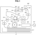
- FIG. 1 is a schematic configuration diagram of an image forming apparatus 900.
- a scanner unit 921 emits a laser beam modulated based on image information to scan a photosensitive drum 919 that is a photosensitive body charged to a predetermined polarity by a charging roller 916.
- a developing unit 917 supplies toner to the electrostatic latent image, and a toner image corresponding to the image information is formed on the photosensitive drum 919.
- sheets S loaded in a sheet feeding cassette 911 are fed one by one by a pickup roller 912, and each sheet S is conveyed by a roller 913 toward a registration roller 914. Further, the sheet S is conveyed from the registration roller 914 to a transfer position formed by the photosensitive drum 919 and a transfer roller 920 in synchronization with a timing when the toner image on the photosensitive drum 919 reaches the transfer position.
- the toner image on the photosensitive drum 919 is transferred to the sheet S while the sheet S passes through the transfer position. Thereafter, the sheet S is heated by a fusing device 1, and the toner image is heated and fixed onto the sheet S.
- the sheet S carrying the fixed toner image is discharged to a tray on an upper part of the image forming apparatus 900 by rollers 926 and 927.
- toner remaining on the photosensitive drum 919 is cleaned by a cleaner 918.
- a motor 930 is a driving source driving the fusing device 1 and the like. Power is supplied from a control circuit 940 connected to a commercial alternating-current power supply 941 to the fusing device 1.
- the photosensitive drum 919, the charging roller 916, the scanner unit 921, the developing unit 917, and the transfer roller 920 described above configure an image forming unit (or image forming means) that forms an unfixed image on the sheet S.
- a cartridge 915 is a unit replaceable for the image forming apparatus 900.
- the scanner unit 921 includes a light source 922, a polygon mirror 923, and a reflective mirror 924.
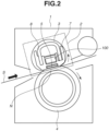
- Fig. 2 is a cross-sectional view of the fusing device 1 in a conveyance direction of the sheet S.
- the fusing device 1 includes a heating device 2 including a cylindrical film 3 as a flexible rotatable first rotor, and a pressure roller 4 as a second rotor that presses the heating device 2 by a pressurizing unit (not illustrated) to form a nip portion N.
- the sheet S is sandwiched and conveyed by the nip portion N, and the toner image on the sheet S is heated to be fixed onto the sheet S.
- Fig. 3 is a schematic configuration diagram of the heating device 2 and the pressure roller 4.
- the heating device 2 and the pressure roller 4 are supported at both ends in a longitudinal direction by a frame (not illustrated) of the fusing device 1.
- the pressure roller 4 is rotationally driven when driving force is transmitted from a driving source (not illustrated) to a driving gear 28.
- the film 3 abutting on the pressure roller 4 is configured to rotate following the pressure roller 4.
- An elongated heater 5 is disposed in an internal space of the film 3.
- the conveyance direction of the sheet S in Fig. 2 is a transverse direction of the heater 5 that is a right-left direction in Fig. 2 .
- a direction orthogonal to the transverse direction is a longitudinal direction of the heater 5 that is a front-back direction in Fig. 2 .
- a direction orthogonal to the transverse direction and the longitudinal direction is a thickness direction of the heater 5 that is an up-down direction in Fig. 2 .
- the heater 5 is disposed to be slidable with an inner peripheral surface of the film 3. Inner surfaces at both ends of the film 3 in the longitudinal direction are supported by flanges 29. Grease is applied between the heater 5 and the film 3 in order to improve slidability.
- the heater 5 is configured to be energized by an energization unit (not illustrated) from a connector 30 that is an electric contact, and to generate heat by receiving power.
- the heater 5 is held by a heater holder 7 that is a holding member provided substantially in parallel with the film 3.
- the nip portion N formed by the film 3 and the pressure roller 4 preferably has a uniform width in a rotation axis direction that is the longitudinal direction of the film 3. Therefore, the heater holder 7 is provided with a metal frame member 8 as a reinforcing member, on an opposite side of the pressure roller 4 with the heater holder 7 in between, in order to reinforce strength against force by pressure contact.
- the frame member 8 receives pressing force from the pressurization unit (not illustrated) via the flanges 29 provided at both ends.
- the frame member 8 as the reinforcing member also serves as a regulation member regulating (or controlling) a position of a thermostat holder 102.
- the heater holder 7 as the holding member can serve as the regulation member regulating the position of the thermostat holder 102.
- Fig. 4 is a schematic configuration diagram of a thermostat unit 100.
- a thermostat 101 as a power shut-off member is held by the thermostat holder 102 as a holding member.
- An abutting portion 101a of the thermostat 101 internally configures an electric contact via a bimetal.
- connection of the electric contact is disconnected by reverse of the bimetal, to shut off power supply (energization) to the heater 5.
- the abutting portion 100a desirably stably abuts on the heater 5. Therefore, the thermostat holder 102 is pressed against the heater 5 by a thermostat spring 103 that includes a compression spring as an urging member.
- An electric wire 104 of the thermostat 101 is housed in an electric wire guide portion 102a of the thermostat holder 102.
- the thermostat spring 103 is disposed on an end side of a folded portion 104a of the electric wire 104 in a longitudinal direction of the thermostat 101.
- Fig. 5 is an exploded diagram illustrating a configuration of each member in the heating device 2.
- Fig. 6 is a cross-sectional view of the heating device 2 in the longitudinal direction.
- Fig. 7 is a cross-sectional view of a vicinity of the thermostat 101 of the heating device 2 in the longitudinal direction.
- the thermostat 101 is disposed such that the abutting portion 101a engages with a hole portion 7a that is an opening provided near a center part of the heater holder 7 in the longitudinal direction.
- the thermostat holder 102 holding the thermostat 101 is disposed at a position sandwiched between the heater holder 7 and the frame member 8, namely, is disposed between the heater holder 7 and the frame member 8 in the thickness direction of the heater 5.
- the thermostat spring 103 provided on one end side of the thermostat holder 102 is locked (or fixed) to the frame member 8, and presses the thermostat holder 102 against the heater 5.
- the thermostat spring 103 provided on one end side of the thermostat holder 102 urges the one end side of the thermostat holder 102 towards the heater 5 such that the thermostat 101 is pressed against the heater 5.
- a fulcrum 102b provided on the other end side of the thermostat holder 102 is also locked (or fixed) to the frame member 8. In other words, the other end side of the thermostat holder 102 is regulated (or held) in position by the frame member 8.
- Fig. 8 is a diagram illustrating relationship of force acting on the thermostat holder 102.
- 2L denotes a distance from the fulcrum 102b of the thermostat holder 102 to the thermostat spring 103
- L denotes a distance from the fulcrum 102b to the abutting portion 101a of the thermostat 101.
- the one end side of the thermostat holder 102 is urged by the thermostat spring 103, and urging force F (white arrow in Fig. 8 ) is generated.
- the urging force F generates a moment T on the other end side of the thermostat holder 102.
- force Fa black arrow in Fig. 8
- a load of the thermostat spring 103 is set to 200 gf.
- the distance from the fulcrum 102b to the abutting portion 101a and the distance from the fulcrum 102b to the thermostat spring 103 have relationship of 1:2; however, the relationship is not limited thereto. In a case where the distance relationship is changed, it is sufficient to appropriately change spring pressure of the thermostat spring 103 based on the above-described relationship of the moment and the force.
- the one end side of the thermostat 101 is urged by the thermostat spring 103, and the fulcrum 102b on the other end side is regulated in position by the frame member 8.
- the configuration requiring the thermostat spring 103 only on one side is adopted, which makes it possible to suppress increase in space by the springs and leads to downsizing.
- a space generated due to disposition of no spring can be utilized as a space for wiring of the electric wire 104, which makes it possible to downsize the heating device 2.
- a thermistor 201 In a second example embodiment, disposition of a thermistor 201 will be described in addition to the thermostat 101. Configurations similar to the configurations according to the above-described first example embodiment, for example, the image forming apparatus, are denoted by similar reference numerals, and detailed descriptions are omitted in the present example embodiment.
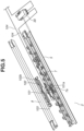
- Fig. 9 is an exploded diagram illustrating a configuration of each member in the heating device 2.
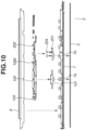
- Fig. 10 is a cross-sectional view of the heating device 2 in the longitudinal direction.
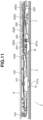
- Fig. 11 is a cross-sectional view of a vicinity of the thermostat 101 of the heating device 2 in the longitudinal direction.
- the heating device 2 includes, in addition to the thermostat 101, the thermistor 201 that is a temperature detection member disposed in a hole portion 7b provided near the center part of the heater holder 7 in the longitudinal direction.
- the thermistor 201 successively detects the temperature and sends a detection result to a central processing unit (CPU) via a signal line 203.
- the CPU serving as a control unit controls power supply to the heater 5 so as to achieve a target temperature based on the detection result of the thermistor 201.
- the thermostat 101 is disposed such that the abutting portion 101a engages with the hole portion 7a provided near the center part of the heater holder 7 in the longitudinal direction.
- the thermostat holder 102 holding the thermostat 101 is disposed at the position sandwiched between the heater holder 7 and the frame member 8 in the thickness direction of the heater 5.
- the thermostat spring 103 provided on the one end side of the thermostat holder 102 is locked to the frame member 8, and presses the thermostat holder 102 against the heater 5.
- the fulcrum 102b provided on the other end side of the thermostat holder 102 is also locked to the frame member 8. In other words, the other end side of the thermostat holder 102 is regulated in position by the frame member 8.
- the thermistor 201 is disposed such that a temperature detection unit 201a engages with the hole portion 7b provided in the heater holder 7, at a position closer to the connector 30 than the thermostat 101 in the longitudinal direction, near the center part of the heater holder 7 in the longitudinal direction. To stably detect the temperature of the heater 5, the temperature detection unit 201a of the thermistor 201 is pressed against the heater 5 at desired pressure by thermistor springs 204 as illustrated in Fig. 10 .
- the electric wire 104 of the thermostat 101 is disposed so as to pass through an upper side of the thermistor 201 in the thickness direction of the heater 5.
- a bundle wire guide 202 as a guide member that guides the electric wire 104 and locks the thermistor springs 204 urging the thermistor 201 to the heater 5, is disposed by being fixed to the heater holder 7.
- Guide ribs 202a of the bundle wire guide 202 are disposed in proximity to the frame member 8, and prevents the electric wire 104 from coming into contact with the frame member 8 and prevents the bundle wire guide 202 from being deformed by reaction force of the thermistor springs 204.
- the electric wire 104 is disposed so as to pass between the bundle wire guide 202 and the guide ribs 202a in the thickness direction of the heater 5, and is connected to the connector 30.
- the bundle wire guide 202 may also be considered as a holding member for holding the thermistor 201 with one end side of the bundle wire guide 202 being urge by the thermistor springs 204 and another end side of the bundle wire guide 202 being regulated or held in position by the heater holder 7 (e.g. by being fixed to the heater holder 7).
- the one end side of the thermostat 101 is urged by the thermostat spring 103, and the fulcrum 102b on the other end side is regulated in position by the frame member 8.
- the configuration requiring the thermostat spring 103 only on one side is adopted, which makes it possible to suppress increase in space by the springs.
- the electric wire 104 is caused to pass through the upper side of the thermistor 201 disposed in the same direction, which makes it possible to downsize the heating device 2.
- thermistor 201 disposition of the thermistor 201 will be described in addition to the thermostat 101.
- Fig. 12 is an exploded diagram illustrating a configuration of each member in the heating device 2.
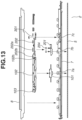
- Fig. 13 is a cross-sectional view of the heating device 2 in the longitudinal direction.
- Fig. 14 is a cross-sectional view of the vicinity of the thermostat 101 of the heating device 2 in the longitudinal direction.
- the heating device 2 includes, in addition to the thermostat 101, the thermistor 201 disposed in the hole portion 7b provided near the center part of the heater holder 7 in the longitudinal direction.
- the thermistor 201 successively detects the temperature of the heater 5, and the CPU serving as the control unit controls power supply to the heater 5 so as to achieve a target temperature, based on a result of the detection by the thermistor 201.
- the thermostat 101 is disposed such that the abutting portion 101a engages with the hole portion 7a provided near the center part of the heater holder 7 in the longitudinal direction.
- the thermostat holder 102 holding the thermostat 101 is disposed at the position sandwiched between the heater holder 7 and the frame member 8 in the thickness direction of the heater 5.
- the thermistor 201 is disposed such that the temperature detection unit 201a engages with the hole portion 7b provided in the heater holder 7, at a position closer to the connector 30 than the thermostat 101 in the longitudinal direction, near the center part of the heater holder 7 in the longitudinal direction. To stably detect the temperature of the heater 5, the temperature detection unit 201a of the thermistor 201 is pressed against the heater 5 at desired pressure by the thermistor springs 204.
- the electric wire 104 of the thermostat 101 is disposed so as to pass through the upper side of the thermistor 201 in the thickness direction of the heater 5.
- the bundle wire guide 202 that guides the electric wire 104 and locks the thermistor springs 204 urging the thermistor 201 against the heater 5 is disposed by being fixed to the heater holder 7 as illustrated in Fig. 13 . More specifically, the bundle wire guide 202 is fixed to a shaft 7c of the heater holder 7 by a push nut 301.
- the push nut 301 is a fastener that is inserted into a shaft not having a groove from a certain direction and is fixed at a predetermined position by catching an outer diameter of the shaft with claws on an inner diameter side.
- the guide ribs 202a of the bundle wire guide 202 are disposed in proximity to the frame member 8, and prevents the electric wire 104 from coming into contact with the frame member 8 and prevents the bundle wire guide 202 from being deformed by reaction force of the thermistor springs 204.
- the electric wire 104 is disposed so as to pass between the bundle wire guide 202 and the guide ribs 202a in the thickness direction of the heater 5, and is connected to the connector 30.
- the fulcrum 102b provided on the other end side of the thermostat holder 102 is locked to a locking portion 202b of the bundle wire guide 202.
- the fulcrum 102b is regulated in position by the locking portion 202b.
- the locking portion 202b can serve as the regulation member regulating the position of the thermostat holder 102.
- the thermostat holder 102 is held on the heater holder 7.
- the thermostat spring 103 provided on the one end side of the thermostat holder 102 is locked to the frame member 8.
- the guide ribs 202a and the locking portion 202b of the bundle wire guide 202 are disposed in proximity to the frame member 8, and are locked to the frame member 8. This prevents the electric wire 104 from coming into contact with the frame member 8 and prevents the bundle wire guide 202 from being deformed by reaction force of the thermistor springs 204.
- the locking portion 202b of the bundle wire guide 202 may be locked not to the frame member 8 but to the other member such as the heater holder 7.
- the one end side of the thermostat 101 is urged by the thermostat spring 103, and the fulcrum 102b on the other end side is regulated in position by the locking portion 202b.
- the configuration requiring the thermostat spring 103 only on one side is adopted, which makes it possible to suppress increase in space by the springs.
- the electric wire 104 is caused to pass through the upper side of the thermistor 201 disposed in the same direction, which makes it possible to downsize the heating device 2.
- the configuration urging the thermostat unit 100 can be applied as a configuration urging not the thermostat 101 but the thermistor 201.
- the thermistor 201 is also held by a holder as a holding member.
- one end side of the holder holding the thermistor 201 can be urged by an urging member, and the other end side can be regulated by a regulation member.
- the configuration in which the thermostat spring 103 urging the one end side of the thermostat 101 is locked to the frame member 8 is described.
- the thermostat spring 103 may be locked not to the frame member 8 but to the other member such as the heater holder 7 as long as pressing force by the thermostat spring 103 can be applied to the thermostat 101.
Landscapes
- Physics & Mathematics (AREA)
- General Physics & Mathematics (AREA)
- Fixing For Electrophotography (AREA)
- Electrophotography Configuration And Component (AREA)
- Control Of Resistance Heating (AREA)
Abstract
Description
- The present invention relates to a heating device and an image forming apparatus such as a copier, a printer, and a facsimile, adopting an electrophotographic system, an electrostatic recording system, or the like.
- As a heating device in an image forming apparatus, a configuration including a film, a heater disposed in an internal space of the film, a holding member holding the heater, and a reinforcing member reinforcing the holding member has been known. Examples of the heater include a sheet heater including a sheet heating element on a ceramic substrate, the heater being held by a heater holder made of a resin as the holding member. A through hole is provided in a part of the holding member in a longitudinal direction, and a thermistor is disposed in a space between the holding member and the reinforcing member to detect a temperature of the heater. The heater is controlled based on the temperature detected by the thermistor. Likewise, a protection element such as a thermostat and a temperature fuse is also provided in the space between the holding member and the reinforcing member. The protection element is also in contact with the heater via another through hole provided in the holding member. The protection element is a power shut-off member that shuts off power supply to the heater in a case where the temperature of the heater exceeds a predetermined temperature.
- The power shut-off member is disposed so as to come into contact with the heater. At this time, if contact pressure to the heater is low or a clearance is generated between the power shut-off member and the heater, responsiveness to the temperature is varied. Therefore, as discussed in
Japanese Patent Application Laid-Open No. 2013-41096 - When both sides of the power shut-off member are urged by the urging members, urging force can be applied; however, a space for arranging the plurality of urging member is necessary and the number of components is increased.
- According to a first aspect of the present invention, there is provided a heating device as specified in claims 1 to 13. According to a second aspect of the present invention, there is provided another heating device as specified in claim 14. According to a third aspect of the present invention, there is provided an image forming apparatus as specified in claim 15.
- Further features of the present invention will become apparent from the following description of example embodiments with reference to the attached drawings.
-
-
Fig. 1 is a schematic configuration diagram of an image forming apparatus. -
Fig. 2 is a cross-sectional view of a fusing device. -
Fig. 3 is a schematic configuration diagram of a heating device and a pressure roller. -
Fig. 4 is a schematic configuration diagram of a thermostat unit. -
Fig. 5 is an exploded diagram illustrating a configuration of each member in the heating device. -
Fig. 6 is a cross-sectional view of the heating device in a longitudinal direction. -
Fig. 7 is a cross-sectional view of a vicinity of the thermostat unit in the longitudinal direction. -
Fig. 8 is a diagram illustrating relationship of force acting on the thermostat unit. -
Fig. 9 is an exploded diagram illustrating a configuration of each member in the heating device. -
Fig. 10 is a cross-sectional view of the heating device in the longitudinal direction. -
Fig. 11 is a cross-sectional view of a vicinity of a thermostat of the heating device in the longitudinal direction. -
Fig. 12 is an exploded diagram illustrating a configuration of each member in the heating device. -
Fig. 13 is a cross-sectional view of the heating device in the longitudinal direction. -
Fig. 14 is a cross-sectional view of the vicinity of the thermostat unit in the longitudinal direction. - Some example embodiments of the present invention will be described below with reference to drawings. The following example embodiments do not limit the invention which is defined by the claims, and the combinations of features described in the example embodiments are not all necessarily essential for the invention.
- A first example embodiment will be described.
Fig. 1 is a schematic configuration diagram of animage forming apparatus 900. When a print signal is generated, ascanner unit 921 emits a laser beam modulated based on image information to scan aphotosensitive drum 919 that is a photosensitive body charged to a predetermined polarity by acharging roller 916. As a result, an electrostatic latent image is formed on thephotosensitive drum 919. A developingunit 917 supplies toner to the electrostatic latent image, and a toner image corresponding to the image information is formed on thephotosensitive drum 919. On the other hand, sheets S loaded in asheet feeding cassette 911 are fed one by one by apickup roller 912, and each sheet S is conveyed by aroller 913 toward aregistration roller 914. Further, the sheet S is conveyed from theregistration roller 914 to a transfer position formed by thephotosensitive drum 919 and atransfer roller 920 in synchronization with a timing when the toner image on thephotosensitive drum 919 reaches the transfer position. - The toner image on the
photosensitive drum 919 is transferred to the sheet S while the sheet S passes through the transfer position. Thereafter, the sheet S is heated by a fusing device 1, and the toner image is heated and fixed onto the sheet S. The sheet S carrying the fixed toner image is discharged to a tray on an upper part of theimage forming apparatus 900 byrollers - Note that toner remaining on the
photosensitive drum 919 is cleaned by acleaner 918. - A
motor 930 is a driving source driving the fusing device 1 and the like. Power is supplied from acontrol circuit 940 connected to a commercial alternating-current power supply 941 to the fusing device 1. Thephotosensitive drum 919, thecharging roller 916, thescanner unit 921, the developingunit 917, and thetransfer roller 920 described above configure an image forming unit (or image forming means) that forms an unfixed image on the sheetS. A cartridge 915 is a unit replaceable for theimage forming apparatus 900. Thescanner unit 921 includes alight source 922, apolygon mirror 923, and areflective mirror 924. - Next, a configuration of the fusing device 1 will be described with reference to
Fig. 2 andFig. 3 .Fig. 2 is a cross-sectional view of the fusing device 1 in a conveyance direction of the sheet S. The fusing device 1 includes aheating device 2 including acylindrical film 3 as a flexible rotatable first rotor, and apressure roller 4 as a second rotor that presses theheating device 2 by a pressurizing unit (not illustrated) to form a nip portion N. The sheet S is sandwiched and conveyed by the nip portion N, and the toner image on the sheet S is heated to be fixed onto the sheet S. -
Fig. 3 is a schematic configuration diagram of theheating device 2 and thepressure roller 4. Theheating device 2 and thepressure roller 4 are supported at both ends in a longitudinal direction by a frame (not illustrated) of the fusing device 1. Thepressure roller 4 is rotationally driven when driving force is transmitted from a driving source (not illustrated) to adriving gear 28. Thefilm 3 abutting on thepressure roller 4 is configured to rotate following thepressure roller 4. - An
elongated heater 5 is disposed in an internal space of thefilm 3. The conveyance direction of the sheet S inFig. 2 is a transverse direction of theheater 5 that is a right-left direction inFig. 2 . A direction orthogonal to the transverse direction is a longitudinal direction of theheater 5 that is a front-back direction inFig. 2 . Further, a direction orthogonal to the transverse direction and the longitudinal direction is a thickness direction of theheater 5 that is an up-down direction inFig. 2 . - The
heater 5 is disposed to be slidable with an inner peripheral surface of thefilm 3. Inner surfaces at both ends of thefilm 3 in the longitudinal direction are supported byflanges 29. Grease is applied between theheater 5 and thefilm 3 in order to improve slidability. - The
heater 5 is configured to be energized by an energization unit (not illustrated) from aconnector 30 that is an electric contact, and to generate heat by receiving power. In the internal space of thefilm 3, theheater 5 is held by aheater holder 7 that is a holding member provided substantially in parallel with thefilm 3. Further, the nip portion N formed by thefilm 3 and thepressure roller 4 preferably has a uniform width in a rotation axis direction that is the longitudinal direction of thefilm 3. Therefore, theheater holder 7 is provided with ametal frame member 8 as a reinforcing member, on an opposite side of thepressure roller 4 with theheater holder 7 in between, in order to reinforce strength against force by pressure contact. Theframe member 8 receives pressing force from the pressurization unit (not illustrated) via theflanges 29 provided at both ends. Although details will be described below, theframe member 8 as the reinforcing member also serves as a regulation member regulating (or controlling) a position of athermostat holder 102. Further, in place of theframe member 8, theheater holder 7 as the holding member can serve as the regulation member regulating the position of thethermostat holder 102. -
Fig. 4 is a schematic configuration diagram of athermostat unit 100. Athermostat 101 as a power shut-off member is held by thethermostat holder 102 as a holding member. An abuttingportion 101a of thethermostat 101 internally configures an electric contact via a bimetal. In a case where a surface of the abutting portion 100a is disposed to abut on theheater 5, and theheater 5 generates heat to a predetermined temperature or more, connection of the electric contact is disconnected by reverse of the bimetal, to shut off power supply (energization) to theheater 5. - To cause the
thermostat 101 to respond to heat of theheater 5 with high responsiveness, the abutting portion 100a desirably stably abuts on theheater 5. Therefore, thethermostat holder 102 is pressed against theheater 5 by athermostat spring 103 that includes a compression spring as an urging member. Anelectric wire 104 of thethermostat 101 is housed in an electricwire guide portion 102a of thethermostat holder 102. Thethermostat spring 103 is disposed on an end side of a foldedportion 104a of theelectric wire 104 in a longitudinal direction of thethermostat 101. -
Fig. 5 is an exploded diagram illustrating a configuration of each member in theheating device 2.Fig. 6 is a cross-sectional view of theheating device 2 in the longitudinal direction.Fig. 7 is a cross-sectional view of a vicinity of thethermostat 101 of theheating device 2 in the longitudinal direction. Thethermostat 101 is disposed such that the abuttingportion 101a engages with ahole portion 7a that is an opening provided near a center part of theheater holder 7 in the longitudinal direction. Thethermostat holder 102 holding thethermostat 101 is disposed at a position sandwiched between theheater holder 7 and theframe member 8, namely, is disposed between theheater holder 7 and theframe member 8 in the thickness direction of theheater 5. In the longitudinal direction of theheater 5, thethermostat spring 103 provided on one end side of thethermostat holder 102 is locked (or fixed) to theframe member 8, and presses thethermostat holder 102 against theheater 5. For example, thethermostat spring 103 provided on one end side of thethermostat holder 102 urges the one end side of thethermostat holder 102 towards theheater 5 such that thethermostat 101 is pressed against theheater 5. Afulcrum 102b provided on the other end side of thethermostat holder 102 is also locked (or fixed) to theframe member 8. In other words, the other end side of thethermostat holder 102 is regulated (or held) in position by theframe member 8. -
Fig. 8 is a diagram illustrating relationship of force acting on thethermostat holder 102. 2L denotes a distance from thefulcrum 102b of thethermostat holder 102 to thethermostat spring 103, and L denotes a distance from thefulcrum 102b to the abuttingportion 101a of thethermostat 101. The one end side of thethermostat holder 102 is urged by thethermostat spring 103, and urging force F (white arrow inFig. 8 ) is generated. The urging force F generates a moment T on the other end side of thethermostat holder 102. As a result, force Fa (black arrow inFig. 8 ) acts on the abuttingportion 101a. From relationship of T = F × 2L = Fa × L, Fa = 2F is established. - In the present example embodiment, to cause the abutting
portion 101a of thethermostat 101 to abut on theheater 5 with the force of 400 gf, a load of thethermostat spring 103 is set to 200 gf. Note that the distance from thefulcrum 102b to the abuttingportion 101a and the distance from thefulcrum 102b to thethermostat spring 103 have relationship of 1:2; however, the relationship is not limited thereto. In a case where the distance relationship is changed, it is sufficient to appropriately change spring pressure of thethermostat spring 103 based on the above-described relationship of the moment and the force. - As described above, the one end side of the
thermostat 101 is urged by thethermostat spring 103, and thefulcrum 102b on the other end side is regulated in position by theframe member 8. This makes it possible to press the abuttingportion 101a against theheater 5 without urging both sides of thethermostat 101 by springs. The configuration requiring thethermostat spring 103 only on one side is adopted, which makes it possible to suppress increase in space by the springs and leads to downsizing. Further, on the other side on which nothermostat spring 103 is disposed, a space generated due to disposition of no spring can be utilized as a space for wiring of theelectric wire 104, which makes it possible to downsize theheating device 2. - In a second example embodiment, disposition of a
thermistor 201 will be described in addition to thethermostat 101. Configurations similar to the configurations according to the above-described first example embodiment, for example, the image forming apparatus, are denoted by similar reference numerals, and detailed descriptions are omitted in the present example embodiment. -
Fig. 9 is an exploded diagram illustrating a configuration of each member in theheating device 2.Fig. 10 is a cross-sectional view of theheating device 2 in the longitudinal direction.Fig. 11 is a cross-sectional view of a vicinity of thethermostat 101 of theheating device 2 in the longitudinal direction. Theheating device 2 includes, in addition to thethermostat 101, thethermistor 201 that is a temperature detection member disposed in ahole portion 7b provided near the center part of theheater holder 7 in the longitudinal direction. Thethermistor 201 successively detects the temperature and sends a detection result to a central processing unit (CPU) via asignal line 203. The CPU serving as a control unit controls power supply to theheater 5 so as to achieve a target temperature based on the detection result of thethermistor 201. - The
thermostat 101 is disposed such that the abuttingportion 101a engages with thehole portion 7a provided near the center part of theheater holder 7 in the longitudinal direction. Thethermostat holder 102 holding thethermostat 101 is disposed at the position sandwiched between theheater holder 7 and theframe member 8 in the thickness direction of theheater 5. In the longitudinal direction of theheater 5, thethermostat spring 103 provided on the one end side of thethermostat holder 102 is locked to theframe member 8, and presses thethermostat holder 102 against theheater 5. Thefulcrum 102b provided on the other end side of thethermostat holder 102 is also locked to theframe member 8. In other words, the other end side of thethermostat holder 102 is regulated in position by theframe member 8. - The
thermistor 201 is disposed such that atemperature detection unit 201a engages with thehole portion 7b provided in theheater holder 7, at a position closer to theconnector 30 than thethermostat 101 in the longitudinal direction, near the center part of theheater holder 7 in the longitudinal direction. To stably detect the temperature of theheater 5, thetemperature detection unit 201a of thethermistor 201 is pressed against theheater 5 at desired pressure bythermistor springs 204 as illustrated inFig. 10 . - As illustrated in
Fig. 11 , theelectric wire 104 of thethermostat 101 is disposed so as to pass through an upper side of thethermistor 201 in the thickness direction of theheater 5. To cause theelectric wire 104 to pass through the upper side of thethermistor 201, abundle wire guide 202 as a guide member that guides theelectric wire 104 and locks the thermistor springs 204 urging thethermistor 201 to theheater 5, is disposed by being fixed to theheater holder 7.Guide ribs 202a of thebundle wire guide 202 are disposed in proximity to theframe member 8, and prevents theelectric wire 104 from coming into contact with theframe member 8 and prevents thebundle wire guide 202 from being deformed by reaction force of the thermistor springs 204. Theelectric wire 104 is disposed so as to pass between thebundle wire guide 202 and theguide ribs 202a in the thickness direction of theheater 5, and is connected to theconnector 30. In addition to guiding theelectric wire 104, thebundle wire guide 202 may also be considered as a holding member for holding thethermistor 201 with one end side of thebundle wire guide 202 being urge by the thermistor springs 204 and another end side of thebundle wire guide 202 being regulated or held in position by the heater holder 7 (e.g. by being fixed to the heater holder 7). - As described above, the one end side of the
thermostat 101 is urged by thethermostat spring 103, and thefulcrum 102b on the other end side is regulated in position by theframe member 8. This makes it possible to press the abuttingportion 101a against theheater 5 without urging the both sides of thethermostat 101 by springs. The configuration requiring thethermostat spring 103 only on one side is adopted, which makes it possible to suppress increase in space by the springs. In addition, theelectric wire 104 is caused to pass through the upper side of thethermistor 201 disposed in the same direction, which makes it possible to downsize theheating device 2. - In a third example embodiment, disposition of the
thermistor 201 will be described in addition to thethermostat 101. Configurations similar to the configurations according to the above-described first and second example embodiments, for example, the image forming apparatus, are denoted by similar reference numerals, and detailed descriptions are omitted in the present example embodiment. -
Fig. 12 is an exploded diagram illustrating a configuration of each member in theheating device 2.Fig. 13 is a cross-sectional view of theheating device 2 in the longitudinal direction.Fig. 14 is a cross-sectional view of the vicinity of thethermostat 101 of theheating device 2 in the longitudinal direction. Theheating device 2 includes, in addition to thethermostat 101, thethermistor 201 disposed in thehole portion 7b provided near the center part of theheater holder 7 in the longitudinal direction. Thethermistor 201 successively detects the temperature of theheater 5, and the CPU serving as the control unit controls power supply to theheater 5 so as to achieve a target temperature, based on a result of the detection by thethermistor 201. - The
thermostat 101 is disposed such that the abuttingportion 101a engages with thehole portion 7a provided near the center part of theheater holder 7 in the longitudinal direction. Thethermostat holder 102 holding thethermostat 101 is disposed at the position sandwiched between theheater holder 7 and theframe member 8 in the thickness direction of theheater 5. Thethermistor 201 is disposed such that thetemperature detection unit 201a engages with thehole portion 7b provided in theheater holder 7, at a position closer to theconnector 30 than thethermostat 101 in the longitudinal direction, near the center part of theheater holder 7 in the longitudinal direction. To stably detect the temperature of theheater 5, thetemperature detection unit 201a of thethermistor 201 is pressed against theheater 5 at desired pressure by the thermistor springs 204. - As illustrated in
Fig. 12 , theelectric wire 104 of thethermostat 101 is disposed so as to pass through the upper side of thethermistor 201 in the thickness direction of theheater 5. To cause theelectric wire 104 to pass through the upper side of thethermistor 201, thebundle wire guide 202 that guides theelectric wire 104 and locks the thermistor springs 204 urging thethermistor 201 against theheater 5, is disposed by being fixed to theheater holder 7 as illustrated inFig. 13 . More specifically, thebundle wire guide 202 is fixed to ashaft 7c of theheater holder 7 by apush nut 301. Thepush nut 301 is a fastener that is inserted into a shaft not having a groove from a certain direction and is fixed at a predetermined position by catching an outer diameter of the shaft with claws on an inner diameter side. As illustrated inFig. 14 , theguide ribs 202a of thebundle wire guide 202 are disposed in proximity to theframe member 8, and prevents theelectric wire 104 from coming into contact with theframe member 8 and prevents thebundle wire guide 202 from being deformed by reaction force of the thermistor springs 204. Theelectric wire 104 is disposed so as to pass between thebundle wire guide 202 and theguide ribs 202a in the thickness direction of theheater 5, and is connected to theconnector 30. - The
fulcrum 102b provided on the other end side of thethermostat holder 102 is locked to a lockingportion 202b of thebundle wire guide 202. In other words, thefulcrum 102b is regulated in position by the lockingportion 202b. - In place of the
frame member 8, the lockingportion 202b can serve as the regulation member regulating the position of thethermostat holder 102. Thethermostat holder 102 is held on theheater holder 7. When theframe member 8 is attached thereto, thethermostat spring 103 provided on the one end side of thethermostat holder 102 is locked to theframe member 8. Theguide ribs 202a and the lockingportion 202b of thebundle wire guide 202 are disposed in proximity to theframe member 8, and are locked to theframe member 8. This prevents theelectric wire 104 from coming into contact with theframe member 8 and prevents thebundle wire guide 202 from being deformed by reaction force of the thermistor springs 204. The lockingportion 202b of thebundle wire guide 202 may be locked not to theframe member 8 but to the other member such as theheater holder 7. - As described above, the one end side of the
thermostat 101 is urged by thethermostat spring 103, and thefulcrum 102b on the other end side is regulated in position by the lockingportion 202b. This makes it possible to press the abuttingportion 101a against theheater 5 without urging the both sides of thethermostat 101 by springs. The configuration requiring thethermostat spring 103 only on one side is adopted, which makes it possible to suppress increase in space by the springs. In addition, theelectric wire 104 is caused to pass through the upper side of thethermistor 201 disposed in the same direction, which makes it possible to downsize theheating device 2. - Note that the configuration urging the
thermostat unit 100 according to each of the first to third example embodiments can be applied as a configuration urging not thethermostat 101 but thethermistor 201. As with thethermostat 101, thethermistor 201 is also held by a holder as a holding member. As described above, one end side of the holder holding thethermistor 201 can be urged by an urging member, and the other end side can be regulated by a regulation member. Further, the configuration in which thethermostat spring 103 urging the one end side of thethermostat 101 is locked to theframe member 8 is described. However, thethermostat spring 103 may be locked not to theframe member 8 but to the other member such as theheater holder 7 as long as pressing force by thethermostat spring 103 can be applied to thethermostat 101. - According to the configuration of any of the example embodiments of the present invention, it is possible to provide the configuration urging the power shut-off member without urging both sides of the power shut-off member by the plurality of urging members.
- While the present invention has been described with reference to example embodiments, it is to be understood that the invention is not limited to the disclosed example embodiments and is defined by the following claims. The scope of the following claims is to be accorded the broadest interpretation so as to encompass all such modifications and equivalent structures and functions.
Claims (15)
- A heating device (2), comprising:an elongated heater (5);a first holding member (7) configured to hold the heater;a power shut-off member (101) configured to shut off power supply to the heater;a second holding member (102) configured to hold the power shut-off member;a first urging member (103) configured to press the power shut-off member against the heater; anda regulation member (7, 8, 202b) configured to regulate a position of the second holding member,wherein, in a longitudinal direction of the heater, one end side of the second holding member (102) is urged by the first urging member, and another end side of the second holding member is regulated in position by the regulation member (7, 8, 202b).
- The heating device according to claim 1, wherein the first urging member is locked to the regulation member.
- The heating device according to claim 1 or 2, further comprising an electric wire (104) connected to the power shut-off member (101), the electric wire being disposed to extend to the other end side of the power shut-off member (101) and being connected to a connector (30) supplying power to the heater.
- The heating device according to claim 3,wherein the electric wire is connected to one end side and another end side of the power shut-off member (101),wherein the electric wire connected to the one end side of the power shut-off member is folded from the one end side to the other end side of the power shut-off member, andwherein the first urging member urges the one end side of the second holding member (102) on an end side of a folded portion of the electric wire (104).
- The heating device according to claim 3 or 4, further comprising:a temperature detection member (201) configured to detect a temperature;a third holding member (202) configured to hold the temperature detection member (201);a second urging member (204) configured to press the temperature detection member against the heater; anda first guide member (202) configured to guide the electric wire (104), wherein, in a thickness direction orthogonal to the longitudinal direction and a transverse direction of the heater, the first guide member is disposed between the temperature detection member and the regulation member (8), andwherein the second urging member is locked to the first guide member.
- The heating device according to claim 5, further comprising a second guide member (202a) configured to guide the electric wire,wherein, in the thickness direction, the second guide member (202a) is disposed between the first guide member (202) and the regulation member (8), andwherein, in the thickness direction, the electric wire is disposed between the first guide member and the second guide member.
- The heating device according to any one of claims 1 to 6, wherein the power shut-off member engages with an opening (7a) of the first holding member and abuts on the heater.
- The heating device according to any one of claims 1 to 7, wherein, in a thickness direction orthogonal to the longitudinal direction and a transverse direction of the heater, the power shut-off member (101) is disposed between the first holding member (7) and the regulation member (8).
- The heating device according to any one of claims 1 to 8, wherein the regulation member is a member (8) reinforcing the first holding member (7).
- The heating device according to claim 1, wherein the regulation member is a part of the first holding member.
- The heating device according to claim 1, further comprising an electric wire (104) connected to the power shut-off member,
wherein the regulation member is a member (202b) guiding the electric wire. - The heating device according to any one of claims 1 to 11, further comprising:a first rotor (3) including the heater in an internal space; anda second rotor (4) configured to abut on the first rotor, and to form a nip portion (N) with the heater.
- The heating device according to claim 12,wherein the first rotor (3) is a cylindrical film,wherein the second rotor (4) is a pressure roller, andwherein the heater abuts on an inner peripheral surface of the cylindrical film.
- A heating device (2), comprising:an elongated heater (5);a first holding member (7) configured to hold the heater;a temperature detection member (201) configured to detect a temperature;a second holding member (202) configured to hold the temperature detection member;an urging member (204) configured to press the temperature detection member against the heater; anda regulation member (7, 7c) configured to regulate a position of the second holding member,wherein, in a longitudinal direction of the heater, one end side of the second holding member is urged by the urging member (204), and another end side of the second holding member is regulated in position by the regulation member.
- An image forming apparatus (900), comprising:image forming means (916, 917, 919, 920, 921) for forming an image on a sheet (S); andthe heating device (2) according to any one of claims 1 to 14, configured to fix the image formed on the sheet.
Applications Claiming Priority (1)
| Application Number | Priority Date | Filing Date | Title |
|---|---|---|---|
| JP2021192726A JP7799453B2 (en) | 2021-11-29 | 2021-11-29 | Heating device and image forming apparatus |
Publications (1)
| Publication Number | Publication Date |
|---|---|
| EP4187325A1 true EP4187325A1 (en) | 2023-05-31 |
Family
ID=84360792
Family Applications (1)
| Application Number | Title | Priority Date | Filing Date |
|---|---|---|---|
| EP22208515.1A Pending EP4187325A1 (en) | 2021-11-29 | 2022-11-21 | Heating device and image forming apparatus |
Country Status (4)
| Country | Link |
|---|---|
| US (2) | US12019385B2 (en) |
| EP (1) | EP4187325A1 (en) |
| JP (1) | JP7799453B2 (en) |
| CN (1) | CN116184790A (en) |
Families Citing this family (2)
| Publication number | Priority date | Publication date | Assignee | Title |
|---|---|---|---|---|
| JP2024089485A (en) * | 2022-12-21 | 2024-07-03 | キヤノン株式会社 | Temperature detection device, fixing device and image forming apparatus |
| JP2024122654A (en) * | 2023-02-28 | 2024-09-09 | ブラザー工業株式会社 | Heating unit |
Citations (5)
| Publication number | Priority date | Publication date | Assignee | Title |
|---|---|---|---|---|
| JP2011128299A (en) * | 2009-12-16 | 2011-06-30 | Canon Inc | Image heating device and image forming device |
| JP2013041096A (en) | 2011-08-15 | 2013-02-28 | Canon Inc | Image heating device |
| US20190004458A1 (en) * | 2017-06-30 | 2019-01-03 | Canon Kabushiki Kaisha | Fixing device |
| US20200183307A1 (en) * | 2018-12-07 | 2020-06-11 | Yuusuke Furuichi | Temperature detector, heating device, fixing device, and image forming apparatus |
| US20200201219A1 (en) * | 2018-12-21 | 2020-06-25 | Kyocera Document Solutions Inc. | Fixing device and image forming apparatus |
Family Cites Families (6)
| Publication number | Priority date | Publication date | Assignee | Title |
|---|---|---|---|---|
| JP2002267543A (en) | 2001-03-09 | 2002-09-18 | Canon Inc | Temperature detection unit and heating device having temperature detection unit |
| US20090097873A1 (en) | 2007-10-16 | 2009-04-16 | Palo Alto Research Center Incorporated | Intermediate roller for sensing temperature of passing surfaces |
| JP5207757B2 (en) | 2008-02-06 | 2013-06-12 | 京セラドキュメントソリューションズ株式会社 | Fixing device and image forming apparatus having the same |
| JP6407002B2 (en) | 2014-12-10 | 2018-10-17 | キヤノン株式会社 | Fixing device |
| JP2017157401A (en) | 2016-03-01 | 2017-09-07 | 富士ゼロックス株式会社 | Heating device and image formation apparatus |
| CN106406054B (en) | 2016-05-24 | 2020-09-11 | 广东风华高新科技股份有限公司 | Printer heating sheet and preparation method thereof |
-
2021
- 2021-11-29 JP JP2021192726A patent/JP7799453B2/en active Active
-
2022
- 2022-11-18 CN CN202211447980.0A patent/CN116184790A/en active Pending
- 2022-11-21 EP EP22208515.1A patent/EP4187325A1/en active Pending
- 2022-11-21 US US18/057,640 patent/US12019385B2/en active Active
-
2024
- 2024-05-20 US US18/669,369 patent/US12474655B2/en active Active
Patent Citations (5)
| Publication number | Priority date | Publication date | Assignee | Title |
|---|---|---|---|---|
| JP2011128299A (en) * | 2009-12-16 | 2011-06-30 | Canon Inc | Image heating device and image forming device |
| JP2013041096A (en) | 2011-08-15 | 2013-02-28 | Canon Inc | Image heating device |
| US20190004458A1 (en) * | 2017-06-30 | 2019-01-03 | Canon Kabushiki Kaisha | Fixing device |
| US20200183307A1 (en) * | 2018-12-07 | 2020-06-11 | Yuusuke Furuichi | Temperature detector, heating device, fixing device, and image forming apparatus |
| US20200201219A1 (en) * | 2018-12-21 | 2020-06-25 | Kyocera Document Solutions Inc. | Fixing device and image forming apparatus |
Also Published As
| Publication number | Publication date |
|---|---|
| US20230168612A1 (en) | 2023-06-01 |
| US12474655B2 (en) | 2025-11-18 |
| JP7799453B2 (en) | 2026-01-15 |
| US20240310760A1 (en) | 2024-09-19 |
| JP2023079314A (en) | 2023-06-08 |
| US12019385B2 (en) | 2024-06-25 |
| CN116184790A (en) | 2023-05-30 |
Similar Documents
| Publication | Publication Date | Title |
|---|---|---|
| US8401414B2 (en) | Fixing device and image forming apparatus incorporating same | |
| US10928767B2 (en) | Heating device with a guide having convex and recess portions and a connector with a conduction terminal | |
| US9678460B2 (en) | Fixing device, image forming apparatus, and fixing method | |
| US9316959B2 (en) | Fixing device | |
| US20240310760A1 (en) | Heating device and image forming apparatus | |
| US8737853B2 (en) | Fixing device having adjustment mechanism for adjusting sheet discharging direction | |
| US20180017910A1 (en) | Fixing device and image forming apparatus | |
| US8428480B2 (en) | Fixing device, image forming apparatus incorporating same, and method of dimensioning fixing device | |
| KR20120079405A (en) | Fusing device and image forming apparatus having the same | |
| US9778606B2 (en) | Fixing device and image forming apparatus | |
| US20210364958A1 (en) | Heating device, image forming apparatus, and thermocompression bonding apparatus | |
| US9829840B2 (en) | Fixing device and image forming apparatus | |
| US10852671B2 (en) | Fixing device including a cleaner to clean a surface of a cleaning target and image forming apparatus incorporating same | |
| JP2018151591A (en) | Fixation device | |
| US10295940B2 (en) | Belt unit and image heating apparatus having a belt unit that includes an insulating holder portion that provides insulation between an exposed portion of a leaf spring and a stay | |
| US11016423B2 (en) | Image forming apparatus having variable fixing temperature and nip width | |
| US10635030B2 (en) | Image heating device | |
| US10698351B1 (en) | Fixing device and image forming apparatus | |
| US11143994B2 (en) | Image heating apparatus | |
| US10444676B2 (en) | Image heating apparatus to mount on an image forming apparatus for fixing an image | |
| US10386759B2 (en) | Belt unit and image heating apparatus | |
| US20080267650A1 (en) | Image forming apparatus | |
| US10591849B2 (en) | Image forming apparatus | |
| JP2018173623A (en) | Image heating device | |
| JP7837747B2 (en) | Fixing device |
Legal Events
| Date | Code | Title | Description |
|---|---|---|---|
| PUAI | Public reference made under article 153(3) epc to a published international application that has entered the european phase |
Free format text: ORIGINAL CODE: 0009012 |
|
| STAA | Information on the status of an ep patent application or granted ep patent |
Free format text: STATUS: THE APPLICATION HAS BEEN PUBLISHED |
|
| AK | Designated contracting states |
Kind code of ref document: A1 Designated state(s): AL AT BE BG CH CY CZ DE DK EE ES FI FR GB GR HR HU IE IS IT LI LT LU LV MC ME MK MT NL NO PL PT RO RS SE SI SK SM TR |
|
| STAA | Information on the status of an ep patent application or granted ep patent |
Free format text: STATUS: REQUEST FOR EXAMINATION WAS MADE |
|
| 17P | Request for examination filed |
Effective date: 20231130 |
|
| RBV | Designated contracting states (corrected) |
Designated state(s): AL AT BE BG CH CY CZ DE DK EE ES FI FR GB GR HR HU IE IS IT LI LT LU LV MC ME MK MT NL NO PL PT RO RS SE SI SK SM TR |
|
| STAA | Information on the status of an ep patent application or granted ep patent |
Free format text: STATUS: EXAMINATION IS IN PROGRESS |
|
| 17Q | First examination report despatched |
Effective date: 20250219 |