EP4187275A1 - Cfar phased array pre-processing using noncoherent and coherent integration in automotive radar systems - Google Patents
Cfar phased array pre-processing using noncoherent and coherent integration in automotive radar systems Download PDFInfo
- Publication number
- EP4187275A1 EP4187275A1 EP22205618.6A EP22205618A EP4187275A1 EP 4187275 A1 EP4187275 A1 EP 4187275A1 EP 22205618 A EP22205618 A EP 22205618A EP 4187275 A1 EP4187275 A1 EP 4187275A1
- Authority
- EP
- European Patent Office
- Prior art keywords
- cfar
- radar
- dimensional matrix
- threshold
- image data
- Prior art date
- Legal status (The legal status is an assumption and is not a legal conclusion. Google has not performed a legal analysis and makes no representation as to the accuracy of the status listed.)
- Granted
Links
Images


Classifications
-
- G—PHYSICS
- G01—MEASURING; TESTING
- G01S—RADIO DIRECTION-FINDING; RADIO NAVIGATION; DETERMINING DISTANCE OR VELOCITY BY USE OF RADIO WAVES; LOCATING OR PRESENCE-DETECTING BY USE OF THE REFLECTION OR RERADIATION OF RADIO WAVES; ANALOGOUS ARRANGEMENTS USING OTHER WAVES
- G01S13/00—Systems using the reflection or reradiation of radio waves, e.g. radar systems; Analogous systems using reflection or reradiation of waves whose nature or wavelength is irrelevant or unspecified
- G01S13/02—Systems using reflection of radio waves, e.g. primary radar systems; Analogous systems
- G01S13/06—Systems determining position data of a target
- G01S13/08—Systems for measuring distance only
- G01S13/32—Systems for measuring distance only using transmission of continuous waves, whether amplitude-, frequency-, or phase-modulated, or unmodulated
- G01S13/34—Systems for measuring distance only using transmission of continuous waves, whether amplitude-, frequency-, or phase-modulated, or unmodulated using transmission of continuous, frequency-modulated waves while heterodyning the received signal, or a signal derived therefrom, with a locally-generated signal related to the contemporaneously transmitted signal
- G01S13/343—Systems for measuring distance only using transmission of continuous waves, whether amplitude-, frequency-, or phase-modulated, or unmodulated using transmission of continuous, frequency-modulated waves while heterodyning the received signal, or a signal derived therefrom, with a locally-generated signal related to the contemporaneously transmitted signal using sawtooth modulation
-
- G—PHYSICS
- G01—MEASURING; TESTING
- G01S—RADIO DIRECTION-FINDING; RADIO NAVIGATION; DETERMINING DISTANCE OR VELOCITY BY USE OF RADIO WAVES; LOCATING OR PRESENCE-DETECTING BY USE OF THE REFLECTION OR RERADIATION OF RADIO WAVES; ANALOGOUS ARRANGEMENTS USING OTHER WAVES
- G01S13/00—Systems using the reflection or reradiation of radio waves, e.g. radar systems; Analogous systems using reflection or reradiation of waves whose nature or wavelength is irrelevant or unspecified
- G01S13/88—Radar or analogous systems specially adapted for specific applications
- G01S13/93—Radar or analogous systems specially adapted for specific applications for anti-collision purposes
- G01S13/931—Radar or analogous systems specially adapted for specific applications for anti-collision purposes of land vehicles
-
- G—PHYSICS
- G01—MEASURING; TESTING
- G01S—RADIO DIRECTION-FINDING; RADIO NAVIGATION; DETERMINING DISTANCE OR VELOCITY BY USE OF RADIO WAVES; LOCATING OR PRESENCE-DETECTING BY USE OF THE REFLECTION OR RERADIATION OF RADIO WAVES; ANALOGOUS ARRANGEMENTS USING OTHER WAVES
- G01S13/00—Systems using the reflection or reradiation of radio waves, e.g. radar systems; Analogous systems using reflection or reradiation of waves whose nature or wavelength is irrelevant or unspecified
- G01S13/02—Systems using reflection of radio waves, e.g. primary radar systems; Analogous systems
- G01S13/06—Systems determining position data of a target
- G01S13/42—Simultaneous measurement of distance and other co-ordinates
-
- G—PHYSICS
- G01—MEASURING; TESTING
- G01S—RADIO DIRECTION-FINDING; RADIO NAVIGATION; DETERMINING DISTANCE OR VELOCITY BY USE OF RADIO WAVES; LOCATING OR PRESENCE-DETECTING BY USE OF THE REFLECTION OR RERADIATION OF RADIO WAVES; ANALOGOUS ARRANGEMENTS USING OTHER WAVES
- G01S13/00—Systems using the reflection or reradiation of radio waves, e.g. radar systems; Analogous systems using reflection or reradiation of waves whose nature or wavelength is irrelevant or unspecified
- G01S13/02—Systems using reflection of radio waves, e.g. primary radar systems; Analogous systems
- G01S13/50—Systems of measurement based on relative movement of target
- G01S13/58—Velocity or trajectory determination systems; Sense-of-movement determination systems
- G01S13/583—Velocity or trajectory determination systems; Sense-of-movement determination systems using transmission of continuous unmodulated waves, amplitude-, frequency-, or phase-modulated waves and based upon the Doppler effect resulting from movement of targets
- G01S13/584—Velocity or trajectory determination systems; Sense-of-movement determination systems using transmission of continuous unmodulated waves, amplitude-, frequency-, or phase-modulated waves and based upon the Doppler effect resulting from movement of targets adapted for simultaneous range and velocity measurements
-
- G—PHYSICS
- G01—MEASURING; TESTING
- G01S—RADIO DIRECTION-FINDING; RADIO NAVIGATION; DETERMINING DISTANCE OR VELOCITY BY USE OF RADIO WAVES; LOCATING OR PRESENCE-DETECTING BY USE OF THE REFLECTION OR RERADIATION OF RADIO WAVES; ANALOGOUS ARRANGEMENTS USING OTHER WAVES
- G01S7/00—Details of systems according to groups G01S13/00, G01S15/00, G01S17/00
- G01S7/02—Details of systems according to groups G01S13/00, G01S15/00, G01S17/00 of systems according to group G01S13/00
- G01S7/28—Details of pulse systems
- G01S7/285—Receivers
- G01S7/292—Extracting wanted echo-signals
- G01S7/2923—Extracting wanted echo-signals based on data belonging to a number of consecutive radar periods
- G01S7/2926—Extracting wanted echo-signals based on data belonging to a number of consecutive radar periods by integration
-
- G—PHYSICS
- G01—MEASURING; TESTING
- G01S—RADIO DIRECTION-FINDING; RADIO NAVIGATION; DETERMINING DISTANCE OR VELOCITY BY USE OF RADIO WAVES; LOCATING OR PRESENCE-DETECTING BY USE OF THE REFLECTION OR RERADIATION OF RADIO WAVES; ANALOGOUS ARRANGEMENTS USING OTHER WAVES
- G01S7/00—Details of systems according to groups G01S13/00, G01S15/00, G01S17/00
- G01S7/02—Details of systems according to groups G01S13/00, G01S15/00, G01S17/00 of systems according to group G01S13/00
- G01S7/28—Details of pulse systems
- G01S7/285—Receivers
- G01S7/292—Extracting wanted echo-signals
- G01S7/2923—Extracting wanted echo-signals based on data belonging to a number of consecutive radar periods
- G01S7/2927—Extracting wanted echo-signals based on data belonging to a number of consecutive radar periods by deriving and controlling a threshold value
-
- G—PHYSICS
- G01—MEASURING; TESTING
- G01S—RADIO DIRECTION-FINDING; RADIO NAVIGATION; DETERMINING DISTANCE OR VELOCITY BY USE OF RADIO WAVES; LOCATING OR PRESENCE-DETECTING BY USE OF THE REFLECTION OR RERADIATION OF RADIO WAVES; ANALOGOUS ARRANGEMENTS USING OTHER WAVES
- G01S7/00—Details of systems according to groups G01S13/00, G01S15/00, G01S17/00
- G01S7/02—Details of systems according to groups G01S13/00, G01S15/00, G01S17/00 of systems according to group G01S13/00
- G01S7/35—Details of non-pulse systems
- G01S7/352—Receivers
- G01S7/354—Extracting wanted echo-signals
-
- G—PHYSICS
- G01—MEASURING; TESTING
- G01S—RADIO DIRECTION-FINDING; RADIO NAVIGATION; DETERMINING DISTANCE OR VELOCITY BY USE OF RADIO WAVES; LOCATING OR PRESENCE-DETECTING BY USE OF THE REFLECTION OR RERADIATION OF RADIO WAVES; ANALOGOUS ARRANGEMENTS USING OTHER WAVES
- G01S7/00—Details of systems according to groups G01S13/00, G01S15/00, G01S17/00
- G01S7/02—Details of systems according to groups G01S13/00, G01S15/00, G01S17/00 of systems according to group G01S13/00
- G01S7/41—Details of systems according to groups G01S13/00, G01S15/00, G01S17/00 of systems according to group G01S13/00 using analysis of echo signal for target characterisation; Target signature; Target cross-section
- G01S7/414—Discriminating targets with respect to background clutter
-
- H—ELECTRICITY
- H04—ELECTRIC COMMUNICATION TECHNIQUE
- H04B—TRANSMISSION
- H04B7/00—Radio transmission systems, i.e. using radiation field
- H04B7/02—Diversity systems; Multi-antenna system, i.e. transmission or reception using multiple antennas
- H04B7/04—Diversity systems; Multi-antenna system, i.e. transmission or reception using multiple antennas using two or more spaced independent antennas
- H04B7/0413—MIMO systems
Definitions
- the present invention is directed in general to radar systems and associated methods of operation.
- the present invention relates to an automotive radar system which uses a constant false alarm rate receiver and associated methods of operation.
- ADAS Advanced Driver Assistance Systems
- DoA Direction of Arrival
- CFAR Constant False Alarm Rate
- CFAR algorithms are used to differentiate between targets and noise, and are characterized by a constant false alarm rate measure of how often noise is classified as a target.
- Various CFAR algorithms were designed to maximize the probability of detecting a target, given an imposed probability of false alarm.
- the cell-averaging CFAR (CA-CFAR) algorithm family is the least complex CFAR algorithm that is suitable for use with systems having low to average computational power, and requires that the input data is a measure of power.
- CA-CFAR algorithms especially CA-CFAR algorithms, are not well suited to detect multiple high SNR targets that are closely spaced together.
- CFAR offers better results when targets have low SNR values, target(s) with a high SNR value will increase the value of the threshold, causing other adjacent targets to be masked by the CFAR threshold.
- the existing CFAR receiver processing solutions are extremely difficult at a practical level by virtue of the balancing performance, complexity, and computational requirements when quickly, accurately, and efficiently identifying one or more radar targets with radar system applications.
- a radar system, apparatus, and methodology are described for detecting one or more targets with a constant false alarm rate detector by estimating an extremely precise CFAR threshold based on a low SNR data set that is generated from non-coherently integrated data, and then applying the estimated CFAR threshold to high SNR data that is generated from coherently integrated data, thereby maximizing the probability of detection without degrading the probability of false alarm.
- the target detecting radar system, apparatus, and method may include a CFAR detector which processes a Range-Doppler-compressed input data stream with a processor core by performing non-coherent integration of samples from the input data stream for storage in a first two-dimensional matrix.
- the Range-Doppler-compressed input data stream is generated by performing an initial image compression step, such as Range-Doppler (or Range-Azimuth compression for synthetic aperture radar applications), to generate a three-dimensional image matrix (e.g., Range-Doppler Matrix) from the receiver channels.
- an initial image compression step such as Range-Doppler (or Range-Azimuth compression for synthetic aperture radar applications)
- the image matrix is non-coherently integrated or combined among all channels (e.g., averaged) to produce a two-dimensional image matrix of non-coherent integration data.
- the CFAR detector includes a CFAR threshold calculating unit that computes a scaled CFAR threshold by using a predetermined scaling or mapping factor ⁇ having a closed form solution.
- the CFAR threshold calculating unit calculates a CFAR threshold T CFAR from the non-coherent integration data, where T CFAR can be a cell-average CFAR threshold T CA-CFAR or an ordered statistics CFAR threshold T OS-CFAR obtained from the non-coherent integrated data.
- the CFAR detector In parallel with processing of the non-coherent integration, the CFAR detector also processes the Range-Doppler-compressed input data stream with an FFT accelerator hardware by performing coherent integration of samples from the input data stream for storage in a second two-dimensional matrix.
- the image matrix is coherently combined among all receive channels in the spatial dimension (e.g., choosing a maximum value) to produce a two-dimensional image matrix of coherent integration data having improve SNR signal characteristics.
- the CFAR detector may include a detector unit that applies the scaled CFAR threshold to the coherently integrated data to detect targets from any input data that exceeds the scaled CFAR threshold, thereby greatly reducing the chance of low SNR targets being masked by the noise floor (as can occur with performing CFAR detection using only non-coherently integrated data) or by closely spaced high SNR targets (as can occur with performing CFAR detection using only coherently integrated data).
- a Fast Fourier Transform (FFT) accelerator may be used to quickly and efficiently perform coherent integration with reduced numerical complexity, and in parallel, a DSP or ARM processor core may be used to perform non-coherent integration.
- FFT Fast Fourier Transform
- constant false alarm rate (CFAR) detection refers to an adaptive algorithm used in radar systems to detect target returns against a background of noise, clutter and interference.
- the role of the constant false alarm rate circuitry is to determine the power threshold above which any return can be considered to probably originate from a target. If this threshold is too low, then more targets will be detected at the expense of increased numbers of false alarms, resulting in a high false alarm rate. Conversely, if the threshold is too high, the false alarm rate will be low, but fewer targets will be detected. In most radar detectors, the threshold is set in order to achieve a required probability of false alarm (or equivalently, false alarm rate or time between false alarms).
- a fixed threshold level can be chosen that provides a specified probability of false alarm.
- unwanted clutter and interference sources mean that the noise level changes both spatially and temporally.
- a changing threshold can be used so that the threshold level is raised and lowered to maintain a constant probability of false alarm. This is known as constant false alarm rate (CFAR) detection.
- CFAR constant false alarm rate
- the threshold level is calculated by estimating the level of the noise floor around the cell under test (CUT). This can be found by taking a block of cells around the CUT and calculating the average power level, typically by ignoring the "guard cells" immediately adjacent to the CUT to avoid corrupting this estimate with power from the CUT itself.
- a target is detected at the CUT if it is both greater than all its adjacent cells and greater than the threshold level.
- This simple approach is called a cell-averaging CFAR (CA-CFAR).
- Other related approaches calculate separate averages for the cells to the left and right of the CUT, and then use the greatest-of or least-of these two power levels to define the local power level. These are referred to as greatest-of CFAR (GO-CFAR) and smallest-of CFAR (SO-CFAR) respectively, and can improve detection when immediately adjacent to areas of clutter.
- GO-CFAR greatest-of CFAR
- SO-CFAR smallest-of CFAR
- the CFAR algorithm used to compute the CA-CFAR threshold 12 is designed to find a threshold which will distinguish the peaks 13-14 generated by targets from the peaks generated by the input signal noise 11.
- the threshold 12 is the product of (1) a pre-computed scaling factor that depends on the desired probability of false alarm P FA and the assumed noise distribution, and (2) a measured/estimated higher statistic of the signal, such as noise variance ⁇ 2 .
- the CFAR algorithm sequentially compares each sample, or cell under test (CUT), to the CA-CFAR threshold 12. If the amplitude of the CUT is larger than the CA-CFAR threshold 12, than it is classified as a detection.
- the range-compressed input signal 11 is generated as
- 2
- the CFAR algorithm generally assumes an exponential distribution of the range-compressed input signal 11, where the variance of the noise is proportional to the average value of the input signal 11.
- the computed CA-CFAR threshold 12 can detect certain high SNR target peaks (e.g., 14), but masks certain low SNR target peaks (e.g., 13).
- FIG. 2 depicts an example range profile 20 where a computed CA-CFAR threshold 22 is applied to a coherently integrated range-compressed input signal 21 for detecting target peaks 23-24 for two targets located at distance samples 308 and 615.
- coherent integration also referred to as coherent combining
- FFT fast Fourier transform
- FMCW frequency modulated continuous wave
- the coherent integration procedure in the spatial domain may use a Fourier transform, and apply global maximum on the absolute values of the output.
- the CFAR algorithm computes and applies the CA-CFAR threshold 22 to find the threshold(s) which will distinguish the peaks 23-24 generated by targets from the peaks generated by the input signal noise 21.
- the SNR is increased which enables the application of the computed CA-CFAR threshold 22 to detect both target peaks 23, 24.
- the use of the "maximum" selection function results prevents the ability of obtaining a precise probability of false alarm P FA with existing CFAR algorithms.
- Figure 3 depicts an example range profile 30 where a computed CA-CFAR threshold 32 is applied to a non-coherently integrated range-compressed input signal 31 for detecting target peaks 33-34 for two targets located at distance samples 308 and 615.
- non-coherent integration also referred to as non-coherent combining
- the CFAR algorithm computes and applies the CA-CFAR threshold 32 to find the threshold(s) which will distinguish the peaks 33-34 generated by targets from the peaks generated by the input signal noise 31.
- the average value of the noise floor is not changed, but the variance is significantly decreased.
- applying the computed CA-CFAR threshold 32 can detect certain high SNR target peaks (e.g., 34), but certain lower SNR target peaks (e.g., 33) are masked.
- Figure 4 depicts an example coherently integrated power spectrum range profile 40 where a scaled CA-CFAR threshold 42 is applied to a coherently integrated range-compressed input signal 41 for detecting target peaks 43-44 for two targets located at distance samples 308 and 615.
- the coherently integrated image input signal 41 may be generated from the Fourier transformed digital spatial domain signals (x(n)) that are output from the receiver channels by performing FFT in the spatial domain (among receive channels) and applying global maximum on the absolute values on the resulting data.
- the scaled CA-CFAR threshold 42 is applied to coherently integrated range-compressed input signal 41 to distinguish the peaks 43-44 generated by targets from the peaks generated by the input signal noise 41.
- coherent integration data the SNR for the targets 43, 44 is increased.
- both the average value and variance of the coherently integrated range-compressed input signal 41 is reduced (as compared to the power spectrum input signal 11).
- the scaled CA-CFAR threshold 42 is computed in a way that is less affected by the presence of high SNR targets to more closely fit the input signal 41 so that both target peaks 43, 44 are detected while maintaining the desired probability of false alarm P FA .
- the scaling factor ⁇ is applied in the same manner for both CA-CFAR and OS-CFAR.
- FIG. 5 depicts a simplified schematic block diagram of a Linear Frequency Modulation (LFM) time-division multiple-input, multiple output (TD-MIMO) automotive radar system 50 which includes an LFM TD-MIMO radar device 51 connected to a radar controller processor 56.
- LFM Linear Frequency Modulation
- TD-MIMO time-division multiple-input, multiple output
- the LFM TD-MIMO radar device 51 may be embodied as a line-replaceable unit (LRU) or modular component that is designed to be replaced quickly at an operating location.
- LRU line-replaceable unit
- the radar controller processor 56 may be embodied as a line-replaceable unit (LRU) or modular component. Although a single or mono-static LFM TD-MIMO radar device 51 is shown, it will be appreciated that additional distributed radar devices may be used to form a distributed or multi-static radar. In addition, the depicted radar system 50 may be implemented in integrated circuit form with the LFM TD-MIMO radar device 51 and the radar controller processor 56 formed with separate integrated circuits (chips) or with a single chip, depending on the application.
- chips integrated circuits
- Each radar device 51 includes one or more transmitting antenna elements TX i and receiving antenna elements RX j connected, respectively, to one or more radio-frequency (RF) transmitter (TX) units 54 and receiver (RX) units 55.
- each radar device e.g., 51
- each radar device is shown as including individual antenna elements (e.g., TX 1,i , RXij) connected, respectively, to three transmitter modules (e.g., 54) and four receiver modules (e.g., 55), but these numbers are not limiting and other numbers are also possible, such as four transmitter modules 54 and six receiver modules 55, or a single transmitter module 54 and/or a single receiver module 55.
- Each radar device 50 also includes a chirp generator 52 which is configured and connected to supply a chirp input signal 53 to the transmitter module(s) 54.
- the chirp generator 52 is connected to receive a separate and independent local oscillator (LO) signal and a chirp start trigger signal, though delays are likely to be different due to the signal path differences and programmable digital delay elements in the signal paths.
- Chirp signals are generated and transmitted to multiple transmitters 54, usually following a pre-defined transmission schedule, where they are filtered at the RF conditioning module 54A and amplified at the power amplifier 54B before being fed to the corresponding transmit antenna TX 1,i and radiated.
- each transmitter element 54 By sequentially using each transmit antenna TX 1,i to transmit successive pulses in the chirp signal, each transmitter element 54 operates in a time-multiplexed fashion in relation to other transmitter elements because they are programmed to transmit identical waveforms on a temporally separated schedule.
- the radar system 50 also includes a radar controller processing unit 56 that is connected to supply input control signals to the radar device 51 and to receive therefrom digital output signals D1 generated in the time domain x(t) by the receiver modules 55.
- the radar controller processing unit 56 may be embodied as a micro-controller unit (MCU) or other processing unit that is configured and arranged for signal processing tasks such as, but not limited to, target identification, computation of target distance, target velocity, and target direction, and generating control signals.
- the radar controller processing unit 56 may, for example, be configured to generate calibration signals, receive data signals, receive sensor signals, generate frequency spectrum shaping signals (such as ramp generation in the case of FMCW radar) and/or register programming or state machine signals for RF (radio frequency) circuit enablement sequences.
- the radar controller processor 56 may be configured to program the transmitter modules 54 to operate in a time-division fashion by sequentially transmitting LFM chirps for coordinated communication between the transmit antennas TX 1,i , RX 1,j .
- each chirp generator 52 generates a chirp signal 53 in response to a chirp start trigger signal and a corresponding reference local oscillator signal (Reference LO).
- the resulting chirp signal 53 from each chirp generator 52 is then processed by the RF conditioning unit 54A and amplified at the power amplifier (PA) 54B which amplifies the signal to a level suitable for transmission as a radar signal by a transmitter antenna unit TX 1,i , TX 2,i .
- the transmitter module 54 may include additional processing circuits, such as a digital-to-analog converter (DAC), phase shifter (or phase rotator), buffer, mixer, filter, and the like.
- DAC digital-to-analog converter
- phase shifter or phase rotator
- the radar signal transmitted by the transmitter antenna unit TX 1,i may be reflected by one or more objects (not shown), and part of the reflected radar signal reaches the receiver antenna units RX 1,i at the radar device 51.
- the received (radio frequency) antenna signal is amplified by a low noise amplifier (LNA) 55A and then fed to a mixer 55B where it is mixed with the transmitted chirp signal generated by the RF conditioning unit 54A.
- the resulting intermediate frequency signal is fed to a band-pass filter (BPF) 55C and may also be amplified and/or filtered with additional receive processing elements (not shown) before being fed to an analog/digital converter (ADC) 55D and output by each receiver module 55 as a digital signal D1.
- LNA low noise amplifier
- ADC analog/digital converter
- the digital signal D1 is processed by the radar modules 57-59 to detect and measure target returns.
- the digital output signals D1 generated by the receiver module 55 may be processed with radar modules 57-59 to construct and accumulate multiple-input multiple-output (MIMO) array outputs to form a MIMO aperture for use in computing the plots generated with spatial (angle) FFT processing, target tracking processing, and other measurement processing.
- MIMO multiple-input multiple-output
- the digital output signals D1 may be processed by one or more fast Fourier transform (FFT) modules 57, such as a fast-time (range) FFT module and slow-time (Doppler) FFT module, thereby generating a three-dimensional range-Doppler map (RDM) 58 which is also called a radar cube having range-doppler-angle dimensions.
- FFT fast Fourier transform
- Doppler slow-time
- the RDM outputs are then passed through one or more CFAR detection modules 59 to obtain the range-Doppler peak detections for use in estimating the direction of arrival for the target return(s), along with spatial angle estimation processing, target tracking processing, and measurement processing, with the result being output to other automotive computing or user interfacing devices for further process or display.
- the digital output signal D1 from each receiver module or channel 55 is evaluated to detect target returns by first generating a range-compressed signal under test.
- the range compressed signal may be generated at the FFT module 57 by taking the Fourier Transform of the complex time domain output signal(s) x(t) acquired from the ADC 55D.
- the radar controller 56 may include a range compression module 57A that is configured to perform fast-time FFT processing on the received radar signal to derive range information, and may also include a doppler compression module 57B that is configured to perform slow-time FFT processing on the received radar signal to derive Doppler information.
- each receive channel will contain information regarding a Range-Doppler Matrix (RDM) 58 which is formed with a plurality of Range-Doppler maps 58A-D generated by a corresponding plurality of receive channels.
- RDM Range-Doppler Matrix
- each target is represented by a Point-Spread-Function (PSF) with the peak located at the range and Doppler shift corresponding to the target.
- PSF Point-Spread-Function
- coherent or “non-coherent” integration refer to the integration of all RDM in the angular domain, denoted with ⁇ in Figure 5 .
- the total number of channels N c corresponds to the number of receive channels, and hence the number of RDMs available for combining.
- the CFAR detector 59 uses existing hardware resources (such as FFT accelerators and Square-Law or Log-Law detectors) to improve processing time and achieve higher angular resolution detection by pre-processing the RDM 58 to identify target detections that can be processed to estimate the direction of arrival, rather than processing the entire raw data of the RDM 59.
- the CFAR detector 59 includes a first coherent integration module 59A in a first processing path which coherently integrates or combines the RDM 58 in the spatial dimension (among receive channels) to improve target SNR before detection.
- the CFAR detector 59 includes a second non-coherent integration module 59B in a second, parallel processing path which non-coherently integrates or combines the RDM 58 by computing the average of the squared absolute values.
- the CFAR detector 59 also includes a threshold computation module 59C which computes a scaled CFAR threshold by using a defined scaling or mapping factor ⁇ that is applied to the CFAR threshold T CFAR .
- the scaled CFAR threshold is applied to the coherently integrated data generated by the coherent integration module 59A, thereby greatly reducing the chance of targets being masked by either noise or other targets.
- a direction of arrival estimation module 60 is connected and configured to process the targets identified by the CFAR detector 59 when estimating the direction of arrival for the detected target returns.
- the reason for including two processing paths is to obtain the benefits, and avoid the drawbacks, from using coherently and non-coherently integrated data.
- applications with high target density such as automotive applications
- the application of existing CFAR thresholds to coherently integrated data can result in high SNR targets that can easily mask low SNR targets since the existing CFAR threshold is increased in their vicinity.
- existing CFAR threshold techniques are not well suited for use with coherently integrated data.
- the second issue is that the noise distribution does not have an analytical solution, making it impossible to mathematically derive a robust CFAR algorithm for such data.
- non-coherent integration is used instead, a highly accurate estimate of the noise power can be obtained, but existing CFAR threshold techniques can result in the low SNR targets being masked by the noise floor.
- the CFAR detector 59 includes separate, parallel processing paths and processor resources for performing coherent combining 59A and non-coherent combining 59B.
- the first coherent integration module 59A may be executed by using an FFT accelerator to perform the coherent integration 59A
- the second non-coherent integration module 59B may be executed by using by using a DSP core to perform the non-coherent integration 59B.
- the FFT accelerator is able to quickly perform the coherent integration processing that would otherwise be too slow if implemented with a DSP core.
- PDF Rayleigh distributed probability density function
- the Maximum likelihood estimate of the noise variance ⁇ w 2 is obtained from setting: ⁇ log p Z z n
- ⁇ w 2 ⁇ ⁇ w 2 0 , where p Z z n
- the average probability of detection P D is obtained by taking the average with respect to the distribution of ⁇ ⁇ w 2 :
- P ⁇ D E P ⁇ D ⁇ ⁇ w 2 ⁇ ⁇ 0 ⁇ P ⁇ D ⁇ ⁇ w 2 p ⁇ ⁇ w 2 ⁇ ⁇ w 2 d ⁇ ⁇ w 2 , where the pdf p ⁇ ⁇ w 2 ⁇ ⁇ w 2 was chosen to model a Swerling 1 target.
- ⁇ CA N P FA ⁇ 1 / N ⁇ 1 .
- ⁇ CA is a constant that does not depend on z. It plays the role of a parameter to set the desired P PA .
- P ⁇ FA P ⁇ D
- SNR 0
- Equations (1)-(13) make sense for single target detection scenarios, multi-target scenarios present situations where there is a high probability for a target to be present within the N samples used for computing the estimated noise variance ⁇ ⁇ w 2 .
- Applying the CFAR algorithm on non-coherently integrated RDM data will significantly reduce the SNR of the targets, resulting in a better estimate of the noise variance ⁇ ⁇ w 2 from Equation (5).
- the CFAR detector 59 connects the threshold computation module 59C to the output of the non-coherent integration module 59B so that the estimated noise average, ⁇ ⁇ w 2 is computed from the non-coherently integrated data.
- the threshold computation module 59C is connected and configured to construct a CFAR threshold that is applied to the coherently integrated data by the threshold application module 59D.
- the Fourier transform module(s) 57 are connected to acquire and process the time-domain signals captured by each ADC at a receiver channel by performing range-doppler compression on the digital output signals D1.
- the CFAR detector 59 is connected to process the Power Spectrum (PS) output from the Fourier transform module(s) 57 using any suitable detector, such as a square-law, linear or log detector.
- the CFAR detector 59 is described as using a square-law detector.
- the Doppler dimension can be ignored.
- a two-dimensional RDM is generated which may be characterized by a Power Spectral Density (PSD) measure.
- PSD Power Spectral Density
- the Power Spectral Density measure is mathematically defined as the statistical average of the Power Spectrum, and is similar to the output of a Spectrum Analyzer which averages all frequency components over a given span within a period of time proportional to the resolution bandpass filter's group delay.
- the time domain signal x ( t ) has real and imaginary Gaussian distributed components, where the variance is ⁇ w 2 / 2 and the mean is 0.
- 2 is exponentially distributed, where the variance is ⁇ w 4 and the mean is ⁇ w 2 .
- the Power Spectral Density (non-coherent integration) signal S xx ( ⁇ ) has a Gaussian distribution (according to the Central Limit Theorem), where the variance is ⁇ w 4 / N c and the mean is ⁇ w 2 .
- Equation (16) is not to be confused with Equation (14), where X ( ⁇ ) represents the Fourier transform of the time-domain signal, x(t).
- the subscript in M N c is NOT an index, but instead represents the number of elements applied to the max ⁇ operator, which for the present disclosure is the number of FFT points used in the spatial domain.
- P r M N c ⁇ T P r X 1 ⁇ 2 ⁇ T , X 2 ⁇ 2 ⁇ T , ... X N c ⁇ 2 ⁇ T .
- M Nc Exponential-Extreme Distributed.
- an extremely accurate value for the noise variance ⁇ w 2 can be obtained by applying a sliding window average or sort on the PSD obtained from the non-coherent integration module 59B.
- the desired probability of false alarm P FA cannot be robustly achieved since the noise floor and noise properties will have been significantly modified by the coherent integration process.
- the threshold computation module 59C is connected and configured to construct a new CFAR threshold that can maintain the desired P FA when applied to the SNR-boosted coherently integrated power spectrum, while maximizing the probability of detection P D .
- the derivation of the scaling factor ⁇ is achieved using the CA-CFAR algorithm, however the result may then be used for any other type of CFAR algorithm, e.g. the OS-CFAR.
- ⁇ N P FA ⁇ 1 / N ⁇ 1 is a deterministic constant which does not depend on the signal.
- the scaling factor ⁇ estimate is computed for a given set of parameters, including Probability of false alarm ( P FA ), Window Size ( N ), and Number of Channels ( Nc ).
- the threshold computation module 59C may be configured to compute a new or scaled CFAR threshold T CA ′ that will be applied to the coherently integrated data.
- the scaling factor parameter ⁇ may be computed offline and can be included in ⁇ CA , thereby adding no numerical complexity to the CFAR algorithm.
- the scaling factor parameter ⁇ is computed in the same way using Equation (28).
- the traditional OS-CFAR scaling factor, ⁇ os is numerically found from Equation (32).
- P FA k N k k ⁇ 1 ! T OS + N ⁇ k ! T OS + N ! .
- FIGS 6-9 depict different range profiles illustrating the application of CA-CFAR thresholds for detecting multiple targets, including closely spaced high SNR and low SNR targets.
- the example range profiles there are four targets located at distance samples 101, 513, 610 and 630, with a high SNR target (at distance sample 610) being closely located next to the lower SNR target (at distance sample 610).
- the power spectrum range profile 60 represents the original noise floor, and the CFAR algorithm computes the CA-CFAR threshold 62 as the product of (1) a pre-computed scaling factor that depends on the desired probability of false alarm P FA and the assumed noise distribution, and (2) the estimated noise variance ⁇ w 2 .
- the range-compressed input signal 61 is generated as
- 2
- the computed CA-CFAR threshold 62 correctly detects certain high SNR target peaks (e.g., 64-65), but masks and fails to detect certain low SNR target peaks (e.g., 63, 66).
- certain high SNR target peaks e.g., 64-65
- certain low SNR target peaks e.g., 63, 66
- there is a non-zero probability of a false detection associated with application of the computed CA-CFAR threshold 62 to the power spectrum input signal 61, as indicated with the false detection 67 that is cause when a noise sample is detected.
- the SNR is increased for targets at distance samples 101, 513, 610 and 630.
- the effective noise floor for which the probability of false alarm is calculated is reduced by 10log 10 ( ⁇ ).
- the computed CA-CFAR threshold 72 can detect three of the target peaks 73-75, but not the lower SNR peak 76 that is close to the high SNR peak 75.
- FIG. 8 there is depicted an example range profile 80 where a computed CA-CFAR threshold 82 is applied to a non-coherently integrated range-compressed input signal 81 for detecting multiple targets, including closely spaced high SNR and low SNR targets.
- the average noise level is unchanged for the targets at distance samples 101, 513, 610 and 630.
- the variance of the noise 81 is reduced which may be viewed as an artificial increase in SNR.
- the computed CA-CFAR threshold 82 can detect two of the target peaks 84-85, but not the lower SNR peak 83 that is masked by the CA-CFAR threshold 82 or the lower SNR peak 86 that is close to the high SNR peak 85.
- the scaled CA-CFAR threshold 92 is applied to coherently integrated range-compressed input signal 91 to distinguish all four peaks 93-96 generated by targets from the peaks generated by the input signal noise 91.
- the SNR for the targets 93-94 is increased.
- both the average value and variance of the coherently integrated range-compressed input signal 91 is reduced.
- the scaled CA-CFAR threshold 92 is computed in a way that is less affected by the presence of high SNR targets to more closely fit the input signal 91 so that all four target peaks 93-96 are detected while maintaining the desired probability of false alarm P FA .
- FIG. 10 illustrates a simplified architectural block diagram of a microcontroller 100 for automotive and industrial high-performance radar applications which may implement the disclosed system, apparatus, and methodology for detecting one or more targets with a cell average-constant false alarm rate detector.
- the microcontroller may be implemented with the NXP S32R45 radar MPU which provides high performance imaging radar as a 32-bit automotive radar microprocessor unit (MPU) based on DSP, Arm ® Cortex ® , and FFT accelerator cores within a single chip.
- MPU automotive radar microprocessor unit
- the microcontroller 100 includes one or more control processor or central processing unit (CPU) subsystems 101, on-chip memory 102 (e.g., volatile or nonvolatile memory), and radar processing platform 103 for providing radar-specific high throughput signal processing.
- the radar processing platform 103 may include one or more digital signal processor (DSP) cores 103A, one or more radar processing hardware accelerators 103B, a data RAM 103C, a chirp generator 103D, and a transceiver interface 103E to provide transmit and receive module control and processing.
- DSP digital signal processor
- the processor(s) 101, on-chip memory 102, and radar processing platform 103 may be connected over an on-chip interconnect 104 to a memory interface 105, (e.g., DDR interface), one or more connectivity modules 106 (e.g., PCIe 2x, FlexPWM, eTimer, IIC, DSPI, etc.), and other modules 107.
- a memory interface 105 e.g., DDR interface
- connectivity modules 106 e.g., PCIe 2x, FlexPWM, eTimer, IIC, DSPI, etc.
- the microcontroller 100 may be implemented as circuitry on a single integrated circuit or system-on-chip (SoC).
- SoC system-on-chip
- the interconnect 104 can be any type of bus structure, including but not limited to a non-coherent interconnect, an advanced high-performance bus (AHB), or an advanced peripheral bus (APB).
- control processor(s) 101 may be any type of processing circuit, including but not limited to a microprocessor (MPU), microcontroller (MCU), digital signal processor (DSP), or another type of processor or processor core with multiple levels of cache memory.
- MPU microprocessor
- MCU microcontroller
- DSP digital signal processor
- the microcontroller 100 may include peripheral devices or special-purpose processors, communication interfaces, timers, encoders/decoders, and one or more external memory interfaces, such as DDR interface or flash interface.
- the external memory interfaces may be connected to external memory, such as DDR memory or flash memory.
- the microcontroller 100 may use the control processor(s) 101 to provide a signal processing toolbox (SPT) which receives digital output signals from the radar processing platform 103 which uses the modules 103A-E to process received radar return signals by applying signal conditioning (e.g., low noise amplification, low/high pass filtering, and analog-to-digital conversion) and signal analysis (e.g., gain, windowing, FFT, and filtering).
- SPT signal processing toolbox
- the resulting digital output signals are then processed by the control processor(s) 101 for detection and tracking to detect one or more targets.
- the control processor(s) may execute control code instructions for a CA-CFAR log detector algorithm which processes range and/or doppler compressed RDM data in parallel with both coherent and non-coherent integration processes.
- an FFT accelerator from the radar processing hardware accelerators 103B may process the range and/or doppler compressed RDM data with a coherently combining process to generate coherently integrated data.
- control code instructions for a CA-CFAR log detector algorithm may be executed by the control processor(s) 101 and/or DSP core 103A to apply the scaled CFAR threshold T CA ' or Tos' to the coherently integrated data by comparing each cell under test with the corresponding scaled CFAR threshold T CA ' or Tos' threshold to detect targets from any input data that exceeds the CA-CFAR or OS-CFAR threshold, respectively, thereby maximizing the probability of detection without degrading the probability of false alarm.
- the microcontroller 100 maximizes the efficiency CFAR detection processing.
- the range/doppler compressed data 102A may be retrieved as a 3D RDM from the memory 102 for storage in the data RAM 103C.
- the 3D RDM is processed in parallel by performing non-coherent integration on the DSP core 103A while simultaneously performing coherent integration using the FFT accelerator in the radar processing hardware accelerator 103B.
- the resulting non-coherent integrated data (generated by the DSP core 103A) and the coherent integrated data (generated by the FFT accelerator 103B) may be stored in the memory 102 and/or data RAM 103C as two-dimensional range-doppler matrices 102B where additional CFAR detection processing is performed. Without using the FFT accelerator to perform coherent combining, the CFAR detection processing would be rather slow.
- Figures 11-14 depict different range profiles illustrating the application of CFAR thresholds for detecting multiple targets, including three closely spaced high SNR targets.
- an example power spectrum range profile 110 for a single receiver channel having a specified probability of false alarm where a computed CA-CFAR threshold 112 is applied to a range-compressed input signal 111 for detecting multiple targets, including three closely spaced high SNR targets.
- the range-compressed input signal 111 is generated as
- 2
- the CFAR algorithm generally assumes an exponential distribution of the range-compressed input signal 111, the variance of the noise is proportional to the average value of the input signal 111, and therefore has a relatively large and "wiggly" variance.
- the computed CA-CFAR threshold 112 correctly detects certain high SNR target peaks (e.g., 114, 116), but masks and fails to detect certain low SNR target peaks (e.g., 113, 115).
- the SNR is increased for targets at distance samples 288, 299, 308 and 615.
- the coherent integration or combining reduces the noise floor by 10log 10 ( ⁇ ).
- the computed CA-CFAR threshold 122 can detect three of the target peaks 123, 125, and 126, but not the lower SNR peak 124 that is close to the high SNR peaks 123, 125.
- FIG. 13 there is depicted an example range profile 130 where a computed CA-CFAR threshold 132 is applied to a non-coherently integrated range-compressed input signal 131 for detecting multiple targets, including three closely spaced high SNR targets.
- the non-coherent integration processing there is no change to the average noise level, but the variance of noise affecting the input signal 131 is reduced.
- the computed CA-CFAR threshold 132 can detect two of the target peaks 135, 136, but not the two lower SNR peak 133, 134 that are close to the high SNR peak 135 and masked by the CA-CFAR threshold 132.
- CA-CFAR threshold 142 is applied to coherently integrated range-compressed input signal 141 to distinguish all four peaks 143-146 generated by targets from the peaks generated by the input signal noise 141.
- the SNR for the targets 143-146 is increased.
- both the average value and variance of the coherently integrated range-compressed input signal 141 is reduced.
- the scaled CA-CFAR threshold 142 is computed in a way that is less affected by the presence of high SNR targets to more closely fit the input signal 141 so that all four target peaks 143-146 are detected while maintaining the desired probability of false alarm P FA .
- there is a non-zero probability of a false detection associated with application of the computed CA-CFAR threshold 142 to the power spectrum input signal 141, as indicated with the false detection 147 that is cause when a noise sample is detected.
- Figures 15-16 there are graphically depictions of probability of false alarm measurements as a function of the number of receive channels Nc for different expected probability of false alarm values.
- Figure 15 depicts the measured probability of false alarm P FA 151 on a sample set of 10 4 Monte-Carlo simulations where only noise is present for different values of Nc between 8 and 192 when the expected P FA value was set to 0.001.
- Figure 16 depicts the measured probability of false alarm P FA 161 on a sample set of 10 4 Monte-Carlo simulations where only noise is present for different values of Nc between 8 and 192 when the expected P FA value was set to .0001.
- the true P PA for values below 192 converges towards twice the expected P FA value. Since this effect is independent of the expected P FA value, one may simply use a P FA half as large to obtain the desired P FA .
- Figure 17 illustrates a simplified flow chart 170 showing the logic for using a cell-average CFAR algorithm which computes a scaled threshold from non-coherently integrated power spectrum data for application to coherently integrated power spectrum data.
- control logic and methodology shown in Figure 17 may be implemented with a combination of hardware and software on a radar controller processor which uses an FFT accelerator to coherently integrate or combine a 3D Range-Doppler-Angle signal into a first 2D RDM signal and also uses processor or microcontroller unit to non-coherently integrate or combine the 3D Range-Doppler-Angle signal into a second 2D RDM signal for implementing a CA-CFAR detector and/or an OS-CFAR detector.
- the radar controller processor is configured to execute the cell average-constant false alarm rate detector algorithm for by estimating an extremely precise CFAR threshold based on a low SNR data set that is generated from non-coherently integrated data, and then applying the estimated CFAR threshold to high SNR data that is generated from coherently integrated data, thereby maximizing the probability of detection without degrading the probability of false alarm.
- the process starts (step 171), such as when the radar system begins the process of sensing the location and movement of one or more target objects using one or more transmit radar signals that are sent over a plurality of transmit antennas.
- the radar system first generates a reference chirp signal (step 172), such as by periodically modulating a transmit radar signal with a frequency and/or phase shift.
- a reference chirp signal may be generated as a Linear Frequency Modulation (LFM) waveform that is distributed to a plurality of transmit channel circuits which are respectively associated with a plurality of transmit antennas.
- LFM Linear Frequency Modulation
- the chirp signals are conditioned and amplified for transmission over the corresponding transmit channel circuits.
- this processing is performed by the transmit channel circuits which each include an RF conditioning module (which filters the chirp signal) and power amplifier (which amplifies the RF conditioning module output for transmission over a corresponding transmit antenna).
- the non-adjacent transmit channel circuits may be controlled to sequentially condition and amplify transmit radar waveforms from non-adjacent transmit antennas.
- each physical or virtual receiver channel generates a digital output signals D1 in the time domain x(t) using any suitable sequence of associated to each physical/virtual receiver.
- each receiver channel may receive and amplify the reflected reference chirp signals from the different transmit channels at a receive processing step 175.
- one or more receive antennas at the receiver module receive target returns from the transmitted reference chirp signal waveforms as (radio frequency) antenna signals for subsequent amplification, such as by using a low noise amplifier to generate an amplified RF signal from the target returns.
- each receiver channel may mix the amplified transmit channel signals with the reference chirp signal at the receiver at receiver mixing step 176 to generate an intermediate frequency (IF) signal.
- the mixing step may be implemented by applying the reference chirp signal to a receiver module mixer which is also connected to receive the amplified transmit channel signals for mixing with the reference chirp signal, thereby generating an intermediate frequency signal.
- each receiver channel may condition the intermediate frequency signal for digital conversion at conditioning step 177.
- the conditioning process includes at least feeding the intermediate frequency signal to a bandpass-pass filter, alone or in combination with additional programmable gain and/or filtering steps, thereby generating a bandpass-filtered signal.
- each receiver channel may digitize the bandpass-filtered conditioned IF signal at ADC step 178, such as by using a high-speed analog/digital converter (ADC) to generate a digital signal output that is suitable for digital processing.
- ADC analog/digital converter
- the digital signal outputs from the receiver channel(s) are acquired and digitally processed at step 179 to generate a range compressed signal where the reflected transmit channel signals are separated in the fast-time FFT or range domain.
- additional digital processing is applied to generate a Doppler compressed signal where the reflected transmit channel signals are separated in the slow-time FFT or Doppler domain.
- each radar may be configured to perform fast-time FFT and slow-time FFT processing on the received radar signal to derive range and Doppler information.
- the frequency offset modulation of the reference chirp signals sent over the N transmission channels enables the spectrum to be divided into N consecutive segments with each being associated with a corresponding transmitter.
- the approach can also be referred to as the LFM range-division (RD) MIMO approach.
- RD range-division
- the fast-time samples associated with distinct transmitters are then recovered (and whose sum and delta components are coherently summed for the case of I-channel only FOM,) and the subsequent MIMO virtual array processing can be carried out.
- the radar controller assembles a three-dimensional Range-Doppler-Angle signal or cube based on the previous receiver channel processing steps.
- the 3D Range-Doppler-Angle signal has range-doppler-angle dimensions, where each entry in the angular dimension corresponds to a receiver channel for a total of Nc entries.
- the 3D Range-Doppler-Angle (RDA) signal is supplied in parallel to separate CFAR phased array pre-processing modules which are used to identify range-Doppler peak detections for use in estimating the direction of arrival for the target return(s).
- a first pre-processing module or step 182 coherent integration of all RDAs in the angular domain is performed on the 3D Range-Doppler-Angle signal.
- the coherent integration or combining step 182 may be implemented with an FFT accelerator which implements matched filtering in the spatial domain (among receive channels) and applies a global maximum function on the absolute values of the matching filter's output.
- the input data is the 3D RDM signal or radar cube, and the output is a first two-dimensional RDM of coherently integrated data.
- non-coherent integration is performed of all RDAs in the angular domain of the 3D Range-Doppler-Angle.
- the non-coherent integration or combining step 183 may be implemented with a processor core which computes an average of the squared absolute values of the samples in the spatial domain (among receive channels).
- the input data is the 3D Range-Doppler-Angle signal or radar cube, and the output is a second two-dimensional RDM of non-coherently integrated data.
- the threshold computation processing may compute the scaled CA-CFAR threshold T CFAR-CA ' as the product ⁇ T CFAR-CA .
- the threshold computation processing may compute the scaled OS-CFAR threshold T CFAR-OS ' as the product ⁇ T CFAR-OS .
- the coherently integrated data is compared to the scaled threshold T CFAR ' (from step 184) to identify target detections. For example, a log detector sample value for the cell under test ( ⁇ CUT ) is compared to the scaled threshold T CFAR ' for purposes of identifying target detections when ⁇ CUT >T CFAR '.
- the processing at step 185 is repeated until all log detector sample values have been evaluated as a cell under test, such as by detecting if the last cell under test has been reached.
- step 186 the target detections identified by the CFAR algorithm processing steps 182-185 are combined to obtain the range-Doppler peak detections.
- step 187 the combined target detections are processed to estimate the direction of arrival before continuing with spatial angle estimation processing, target tracking processing, and measurement processing (step 188), with the result being output to other automotive computing or user interfacing devices for further process or display.
- a vehicle radar system, apparatus and method use a radar control processing unit generate compressed radar data signals, to apply the compressed radar data signals in parallel as a three-dimensional matrix to a coherent integrator (which generates a two-dimensional matrix of coherently integrated image data) and a non-coherent integrator (which generates a two-dimensional matrix of non-coherently integrated image data), and to generate a constant false alarm rate (CFAR) threshold from the two-dimensional matrix of non-coherently integrated image data for application to the two-dimensional matrix of coherently integrated image data to detect one or more targets in the MIMO radar signal returns from sample values from the two-dimensional matrix of coherently integrated image data that exceed the CFAR threshold.
- CFAR constant false alarm rate
- a vehicle radar system, apparatus and method use a radar control processing unit to apply CFAR phased array pre-processing to compressed radar data signals by using a constant false alarm rate (CFAR) detector which non-coherently integrates the compressed radar data signals into sample values of a first RDM and which coherently integrates the compressed radar data signals into sample values of a second RDM which are used to compute a scaled CFAR threshold that is applied to the coherently integrated sample values of the first RDM data.
- the compressed radar data signals may be generated as three-dimensional Range-Doppler Matrices or Synthetic Aperture Radar Images, and the first and second RDMs may each be generated as two-dimensional matrices.
- the scaled CFAR threshold may be computed by multiplying a CA-CFAR threshold (or an OS-CFAR threshold) by the computed CFAR scaling factor ⁇ .
- the disclosed radar system includes a radio-frequency (RF) transmitter unit and first plurality of transmit antennas which are connected and controlled by the radar control processing unit to transmit MIMO radar signals.
- the disclosed radar system also includes an RF receiver unit and a first plurality of receive antennas which are connected and controlled by the radar control processing unit to generate digital output signals from MIMO radar signal returns received in response to the MIMO radar signals.
- the disclosed radar control processing unit is configured as a constant false alarm rate (CFAR) detector to generate compressed radar data signals from the digital output signals.
- CFAR constant false alarm rate
- the radar control processing unit may be configured as a CFAR square-law detector or a CFAR log detector.
- the compressed radar data signals are applied in parallel as an n dimensional matrix to a coherent integrator and a non-coherent integrator.
- the coherent integrator generates an n-1 dimensional matrix of coherently integrated image data from the compressed radar data signals.
- the non-coherent integrator generates an n-1 dimensional matrix of non-coherently integrated image data from the compressed radar data signals.
- the coherent integrator uses a fast Fourier transform (FFT) accelerator to generate the n-1 dimensional matrix of coherently integrated image data
- the non-coherent integrator uses a processor core to generate a n-1 dimensional matrix of non-coherently integrated image data.
- the coherent integrator may be configured to generate the n-1 dimensional matrix of coherently integrated image data by performing a matched filtering process in a spatial domain of the n dimensional matrix of compressed radar data signals and applying a global maximum on absolute values of output data from the matched filtering process.
- the non-coherent integrator may be configured to generate the n-1 dimensional matrix of non-coherently integrated image data by computing an average of squared absolute values of the samples in a spatial domain of the n dimensional matrix of compressed radar data signals.
- the disclosed radar control processing unit is configured to generate a CFAR threshold from the n-1 dimensional matrix of non-coherently integrated image data.
- the disclosed radar control processing unit is configured to detect one or more targets in the MIMO radar signal returns by applying the CFAR threshold to the n-1 dimensional matrix of coherently integrated image data to detect sample values from the n-1 dimensional matrix of coherently integrated image data that exceed the CFAR threshold.
- OS-CFAR ordered statistics CFAR
- CA-CFAR cell-average CFAR
- MIMO radar signals are transmitted from transit antennas in a plurality of transmit and receive antennas, and MIMO radar signal returns are received at receive antennas in the plurality of transmit and receive antennas.
- the MIMO radar signal returns are processed with a plurality of receive channels to generate compressed radar data signals as a three-dimensional matrix that are supplied in parallel to a coherent integrator and a non-coherent integrator in a CFAR detector.
- the MIMO radar signal returns are processed to generate the compressed radar data signals as a three-dimensional matrix of range and Doppler compressed image data.
- the disclosed methodology also coherently combines the compressed radar data signals at the coherent integrator to generate a two-dimensional matrix of coherently integrated image data from the compressed radar data signals.
- the disclosed methodology non-coherently combines the compressed radar data signals at the non-coherent integrator to generate a two-dimensional matrix of non-coherently integrated image data from the compressed radar data signals.
- the disclosed methodology also generates a CFAR threshold from the two-dimensional matrix of non-coherently integrated image data.
- OS-CFAR ordered statistics CFAR
- CA-CFAR cell-average CFAR
- the compressed radar data signals are coherently combined by using a fast Fourier transform (FFT) accelerator to compress the three-dimensional matrix of range and Doppler compressed image data into the two-dimensional matrix of coherently integrated image data
- the compressed radar data signals are non-coherently combined by using a processor core to compress the three-dimensional matrix of range and Doppler compressed image data into the two-dimensional matrix of non-coherently integrated image data.
- the compressed radar data signals are coherently combined by performing a matched filtering process in a spatial domain of the three-dimensional matrix of compressed radar data signals and applying a global maximum on absolute values of output data from the matched filtering process.
- the compressed radar data signals may be non-coherently combined by computing an average of squared absolute values of the samples in a spatial domain of the three-dimensional matrix of compressed radar data signals.
- the disclosed methodology applies the CFAR threshold to the two-dimensional matrix of coherently integrated image data to detect sample values from the two-dimensional matrix of coherently integrated image data that exceed the CFAR threshold, thereby identifying one or more targets in the MIMO radar signal returns.
- a transmitter is configured to transmit a first transmit signal and a second transmit signal.
- the radar apparatus also includes a receiver that is configured to produce digital output signals from first and second transmit signal returns received in response to the first and second transmit signals.
- the radar apparatus includes a digital signal processor configured to process the digital output signals with a CFAR detector.
- the digital signal processor is configured to coherently combine the range and Doppler compressed radar data signals at the CFAR detector to generate an n-1 dimensional matrix of coherently integrated image data from the range and Doppler compressed radar data signals.
- the digital signal processor is configured to non-coherently combine the range and Doppler compressed radar data signals at the CFAR detector to generate an n-1 dimensional matrix of non-coherently integrated image data from the compressed radar data signals.
- the CFAR detector may use a fast Fourier transform (FFT) accelerator to generate the n-1 dimensional matrix of coherently integrated image data, and may use a processor core to generate a n-1 dimensional matrix of non-coherently integrated image data.
- FFT fast Fourier transform
- the digital signal processor may be configured to coherently combine the range and Doppler compressed radar data signals by performing a matched filtering process in a spatial domain of the n dimensional matrix of compressed radar data signals and applying a global maximum on absolute values of output data from the matched filtering process.
- the digital signal processor may be configured to non-coherently combine the range and Doppler compressed radar data signals by computing an average of squared absolute values of the samples in a spatial domain of the n dimensional matrix of compressed radar data signals.
- the digital signal processor is configured to generate a CFAR threshold from the n-1 dimensional matrix of non-coherently integrated image data, and to apply the CFAR threshold to the n-1 dimensional matrix of coherently integrated image data to detect sample values from the n-1 dimensional matrix of coherently integrated image data that exceed the CFAR threshold, thereby identifying one or more targets in the MIMO radar signal returns.
- the CFAR detector may be a square-law detector or a log detector or other suitable CFAR detector.
Landscapes
- Engineering & Computer Science (AREA)
- Radar, Positioning & Navigation (AREA)
- Remote Sensing (AREA)
- Physics & Mathematics (AREA)
- Computer Networks & Wireless Communication (AREA)
- General Physics & Mathematics (AREA)
- Electromagnetism (AREA)
- Signal Processing (AREA)
- Radar Systems Or Details Thereof (AREA)
Abstract
Description
- The present invention is directed in general to radar systems and associated methods of operation. In one aspect, the present invention relates to an automotive radar system which uses a constant false alarm rate receiver and associated methods of operation.
- To improve the safety of vehicle and passengers, Advanced Driver Assistance Systems (ADAS) systems use radar-based detection to provide reliable and accurate details of a vehicle's surroundings and to assist drivers to sense the on-road potential hazards in case of blocked vision or poor visibility conditions. In recent years, ADAS radars have seen an exponential growth in angular resolution requirements, but the requirement of obtaining high resolution Direction of Arrival (DoA) estimations can be computationally exhaustive, and even limit real-time capabilities of the system. In addition, the cost and space constraints of implementing radar systems on a vehicle, such as limits on the number of channels and antennas that may be used, can further constrain the detection processing capabilities.
- As a result of these processing constraints, the computationally exhaustive super-resolution radar detection algorithms (such as MUSIC or ESPRIT) can rarely be applied on the entire raw data cube. It is thus preferred to apply DoA estimation on detections, rather than process the entire raw data, such as by using Constant False Alarm Rate (CFAR) detection algorithms to detect target returns against a background of noise, clutter and interference. Arguably representing the most important radar processing step, CFAR algorithms are used to differentiate between targets and noise, and are characterized by a constant false alarm rate measure of how often noise is classified as a target. Various CFAR algorithms were designed to maximize the probability of detecting a target, given an imposed probability of false alarm. For example, the cell-averaging CFAR (CA-CFAR) algorithm family is the least complex CFAR algorithm that is suitable for use with systems having low to average computational power, and requires that the input data is a measure of power. However, CFAR algorithms, especially CA-CFAR algorithms, are not well suited to detect multiple high SNR targets that are closely spaced together. And while CFAR offers better results when targets have low SNR values, target(s) with a high SNR value will increase the value of the threshold, causing other adjacent targets to be masked by the CFAR threshold.
- As seen from the foregoing, the existing CFAR receiver processing solutions are extremely difficult at a practical level by virtue of the balancing performance, complexity, and computational requirements when quickly, accurately, and efficiently identifying one or more radar targets with radar system applications.
- The present invention may be understood, and its numerous objects, features and advantages obtained, when the following detailed description of a preferred embodiment is considered in conjunction with the following drawings.
-
Figure 1 depicts an example range profile for a CA-CFAR threshold that is applied to a range-compressed input signal for detecting two targets. -
Figure 2 depicts an example range profile for a CA-CFAR threshold that is applied to a coherently integrated range-compressed input signal for detecting two targets. -
Figure 3 depicts an example range profile for a CA-CFAR threshold that is applied to a non-coherently integrated range-compressed input signal for detecting two targets. -
Figure 4 depicts an example range profile for a scaled CA-CFAR threshold that is applied to a coherently integrated range-compressed input signal for detecting two targets in accordance with selected embodiments of the present disclosure. -
Figure 5 is a simplified schematic block diagram of an LFM MIMO automotive radar system in accordance with selected embodiments of the present disclosure. -
Figure 6 depicts an example range profile for a CA-CFAR threshold that is applied to a range-compressed input signal for detecting multiple targets, including closely spaced high SNR and low SNR targets. -
Figure 7 depicts an example range profile for a CA-CFAR threshold that is applied to a coherently integrated range-compressed input signal for detecting multiple targets, including closely spaced high SNR and low SNR targets. -
Figure 8 depicts an example range profile for a CA-CFAR threshold that is applied to a non-coherently integrated range-compressed input signal for detecting multiple targets, including closely spaced high SNR and low SNR targets. -
Figure 9 depicts an example range profile for a scaled CA-CFAR threshold that is applied to a coherently integrated range-compressed input signal for detecting multiple targets, including closely spaced high SNR and low SNR targets in accordance with selected embodiments of the present disclosure. -
Figure 10 is a simplified architectural block diagram of a microcontroller system for automotive and industrial high-performance radar applications in accordance with selected embodiments of the present disclosure. -
Figure 11 depicts an example range profile for a CA-CFAR threshold that is applied to a range-compressed input signal for detecting multiple targets, including three closely spaced high SNR targets. -
Figure 12 depicts an example range profile for a CA-CFAR threshold that is applied to a coherently integrated range-compressed input signal for detecting multiple targets, including three closely spaced high SNR targets. -
Figure 13 depicts an example range profile for a CA-CFAR threshold that is applied to a non-coherently integrated range-compressed input signal for detecting multiple targets, including three closely spaced high SNR targets. -
Figure 14 depicts an example range profile for a scaled CA-CFAR threshold that is applied to a coherently integrated range-compressed input signal for detecting multiple targets, including three closely spaced high SNR targets in accordance with selected embodiments of the present disclosure. -
Figures 15-16 are graphical depictions of measured probability of false alarm as a function of the number of receive channels for different expected probability of false alarm values. -
Figure 17 illustrates a simplified flow chart showing the logic for using a cell-average CFAR algorithm which computes a scaled threshold from non-coherently integrated power spectrum data for application to coherently integrated power spectrum data in accordance with selected embodiments of the present disclosure. - A radar system, apparatus, and methodology are described for detecting one or more targets with a constant false alarm rate detector by estimating an extremely precise CFAR threshold based on a low SNR data set that is generated from non-coherently integrated data, and then applying the estimated CFAR threshold to high SNR data that is generated from coherently integrated data, thereby maximizing the probability of detection without degrading the probability of false alarm. To this end, the target detecting radar system, apparatus, and method may include a CFAR detector which processes a Range-Doppler-compressed input data stream with a processor core by performing non-coherent integration of samples from the input data stream for storage in a first two-dimensional matrix. In selected embodiments, the Range-Doppler-compressed input data stream is generated by performing an initial image compression step, such as Range-Doppler (or Range-Azimuth compression for synthetic aperture radar applications), to generate a three-dimensional image matrix (e.g., Range-Doppler Matrix) from the receiver channels. Next, the image matrix is non-coherently integrated or combined among all channels (e.g., averaged) to produce a two-dimensional image matrix of non-coherent integration data. In addition, the CFAR detector includes a CFAR threshold calculating unit that computes a scaled CFAR threshold by using a predetermined scaling or mapping factor β having a closed form solution. In selected embodiments, the CFAR threshold calculating unit calculates a CFAR threshold TCFAR from the non-coherent integration data, where TCFAR can be a cell-average CFAR threshold TCA-CFAR or an ordered statistics CFAR threshold TOS-CFAR obtained from the non-coherent integrated data. In addition, the CFAR threshold calculating unit computes a scaling factor

- In the context of the present disclosure, it will be appreciated that constant false alarm rate (CFAR) detection refers to an adaptive algorithm used in radar systems to detect target returns against a background of noise, clutter and interference. The role of the constant false alarm rate circuitry is to determine the power threshold above which any return can be considered to probably originate from a target. If this threshold is too low, then more targets will be detected at the expense of increased numbers of false alarms, resulting in a high false alarm rate. Conversely, if the threshold is too high, the false alarm rate will be low, but fewer targets will be detected. In most radar detectors, the threshold is set in order to achieve a required probability of false alarm (or equivalently, false alarm rate or time between false alarms). If the background against which targets are to be detected is constant with time and space, then a fixed threshold level can be chosen that provides a specified probability of false alarm. However, in most fielded systems, unwanted clutter and interference sources mean that the noise level changes both spatially and temporally. In such cases, a changing threshold can be used so that the threshold level is raised and lowered to maintain a constant probability of false alarm. This is known as constant false alarm rate (CFAR) detection. In most CFAR detection schemes, the threshold level is calculated by estimating the level of the noise floor around the cell under test (CUT). This can be found by taking a block of cells around the CUT and calculating the average power level, typically by ignoring the "guard cells" immediately adjacent to the CUT to avoid corrupting this estimate with power from the CUT itself. Once the threshold level is calculated as the local average power level, a target is detected at the CUT if it is both greater than all its adjacent cells and greater than the threshold level. This simple approach is called a cell-averaging CFAR (CA-CFAR). Other related approaches calculate separate averages for the cells to the left and right of the CUT, and then use the greatest-of or least-of these two power levels to define the local power level. These are referred to as greatest-of CFAR (GO-CFAR) and smallest-of CFAR (SO-CFAR) respectively, and can improve detection when immediately adjacent to areas of clutter.
- To provide additional details for an improved contextual understanding of the present disclosure, reference is now made to
Figure 1 which depicts an example powerspectrum range profile 10 for a single receiver channel where a computed CA-CFAR threshold 12 is applied having a specified probability of false alarm (e.g., PFA = 10-4) to a range-compressedinput signal 11 for detecting target peaks 13-14 for two targets located atdistance samples CFAR threshold 12 is designed to find a threshold which will distinguish the peaks 13-14 generated by targets from the peaks generated by theinput signal noise 11. Generally speaking, thethreshold 12 is the product of (1) a pre-computed scaling factor that depends on the desired probability of false alarm PFA and the assumed noise distribution, and (2) a measured/estimated higher statistic of the signal, such as noise variance σ 2. To detect targets 13-14 from theinput signal 11, the CFAR algorithm sequentially compares each sample, or cell under test (CUT), to the CA-CFAR threshold 12. If the amplitude of the CUT is larger than the CA-CFAR threshold 12, than it is classified as a detection. As depicted in the example powerspectrum range profile 10, the range-compressedinput signal 11 is generated as |X(ω)|2 = |F{x(t)}|2 to be the squared magnitude of the Fourier transform of the digital time domain signal (x(t)) that is output from the receiver channel. The CFAR algorithm generally assumes an exponential distribution of the range-compressedinput signal 11, where the variance of the noise is proportional to the average value of theinput signal 11. As a result of the range-compressedinput signal 11 having a relatively large and "wiggly" variance that is proportional to the noise average, the computed CA-CFAR threshold 12 can detect certain high SNR target peaks (e.g., 14), but masks certain low SNR target peaks (e.g., 13). - To provide additional details for an improved contextual understanding of the present disclosure, reference is now made to
Figure 2 which depicts anexample range profile 20 where a computed CA-CFAR threshold 22 is applied to a coherently integrated range-compressedinput signal 21 for detecting target peaks 23-24 for two targets located atdistance samples CFAR threshold 22 to find the threshold(s) which will distinguish the peaks 23-24 generated by targets from the peaks generated by theinput signal noise 21. As depicted in the coherently integrated powerspectrum range profile 20, theinput signal 21 is generated as MNc (ωn ) = max{|F{X(ωn )}/Nc )|2} to be the maximum value selected from the squared magnitude of the Fourier transform in the spatial dimension (among the Nc Range-Doppler matrices) of the frequency domain signal (X(ωn )) divided by the number of channels Nc. As a result of the coherent integration processing, the SNR is increased which enables the application of the computed CA-CFAR threshold 22 to detect both target peaks 23, 24. However, the use of the "maximum" selection function results prevents the ability of obtaining a precise probability of false alarm PFA with existing CFAR algorithms. - To provide additional details for an improved contextual understanding of the present disclosure, reference is now made to
Figure 3 which depicts anexample range profile 30 where a computed CA-CFAR threshold 32 is applied to a non-coherently integrated range-compressedinput signal 31 for detecting target peaks 33-34 for two targets located atdistance samples CFAR threshold 32 to find the threshold(s) which will distinguish the peaks 33-34 generated by targets from the peaks generated by theinput signal noise 31. As depicted in the non-coherently integrated powerspectrum range profile 30, theinput signal 31 is generated as
CFAR threshold 32 can detect certain high SNR target peaks (e.g., 34), but certain lower SNR target peaks (e.g., 33) are masked. - To provide additional details for an improved understanding of selected embodiments of the present disclosure, reference is now made to
Figure 4 which depicts an example coherently integrated powerspectrum range profile 40 where a scaled CA-CFAR threshold 42 is applied to a coherently integrated range-compressedinput signal 41 for detecting target peaks 43-44 for two targets located atdistance samples image input signal 41 may be generated from the Fourier transformed digital spatial domain signals (x(n)) that are output from the receiver channels by performing FFT in the spatial domain (among receive channels) and applying global maximum on the absolute values on the resulting data. In this example, the CFAR algorithm computes and applies the scaled CA-CFAR threshold 42 by first calculating a CFAR threshold TCA from the non-coherent integration data, and then applying a scaling factor
input signal 41 to distinguish the peaks 43-44 generated by targets from the peaks generated by theinput signal noise 41. As a result of using coherent integration data, the SNR for thetargets input signal 41 is reduced (as compared to the power spectrum input signal 11). Finally, the scaled CA-CFAR threshold 42 is computed in a way that is less affected by the presence of high SNR targets to more closely fit theinput signal 41 so that both target peaks 43, 44 are detected while maintaining the desired probability of false alarm PFA. The scaling factor β is applied in the same manner for both CA-CFAR and OS-CFAR. - To illustrate the design and operation of an LFM MIMO automotive radar system in which CFAR phased array pre-processing uses non-coherent and coherent integration to detect target returns, reference is now made to
Figure 5 which depicts a simplified schematic block diagram of a Linear Frequency Modulation (LFM) time-division multiple-input, multiple output (TD-MIMO)automotive radar system 50 which includes an LFM TD-MIMO radar device 51 connected to aradar controller processor 56. In selected embodiments, the LFM TD-MIMO radar device 51 may be embodied as a line-replaceable unit (LRU) or modular component that is designed to be replaced quickly at an operating location. Similarly, theradar controller processor 56 may be embodied as a line-replaceable unit (LRU) or modular component. Although a single or mono-static LFM TD-MIMO radar device 51 is shown, it will be appreciated that additional distributed radar devices may be used to form a distributed or multi-static radar. In addition, the depictedradar system 50 may be implemented in integrated circuit form with the LFM TD-MIMO radar device 51 and theradar controller processor 56 formed with separate integrated circuits (chips) or with a single chip, depending on the application. - Each
radar device 51 includes one or more transmitting antenna elements TXi and receiving antenna elements RXj connected, respectively, to one or more radio-frequency (RF) transmitter (TX)units 54 and receiver (RX)units 55. For example, each radar device (e.g., 51) is shown as including individual antenna elements (e.g., TX1,i, RXij) connected, respectively, to three transmitter modules (e.g., 54) and four receiver modules (e.g., 55), but these numbers are not limiting and other numbers are also possible, such as fourtransmitter modules 54 and sixreceiver modules 55, or asingle transmitter module 54 and/or asingle receiver module 55. Eachradar device 50 also includes achirp generator 52 which is configured and connected to supply achirp input signal 53 to the transmitter module(s) 54. To this end, thechirp generator 52 is connected to receive a separate and independent local oscillator (LO) signal and a chirp start trigger signal, though delays are likely to be different due to the signal path differences and programmable digital delay elements in the signal paths. Chirp signals are generated and transmitted tomultiple transmitters 54, usually following a pre-defined transmission schedule, where they are filtered at theRF conditioning module 54A and amplified at thepower amplifier 54B before being fed to the corresponding transmit antenna TX1,i and radiated. By sequentially using each transmit antenna TX1,i to transmit successive pulses in the chirp signal, eachtransmitter element 54 operates in a time-multiplexed fashion in relation to other transmitter elements because they are programmed to transmit identical waveforms on a temporally separated schedule. - The
radar system 50 also includes a radarcontroller processing unit 56 that is connected to supply input control signals to theradar device 51 and to receive therefrom digital output signals D1 generated in the time domain x(t) by thereceiver modules 55. In selected embodiments, the radarcontroller processing unit 56 may be embodied as a micro-controller unit (MCU) or other processing unit that is configured and arranged for signal processing tasks such as, but not limited to, target identification, computation of target distance, target velocity, and target direction, and generating control signals. The radarcontroller processing unit 56 may, for example, be configured to generate calibration signals, receive data signals, receive sensor signals, generate frequency spectrum shaping signals (such as ramp generation in the case of FMCW radar) and/or register programming or state machine signals for RF (radio frequency) circuit enablement sequences. In addition, theradar controller processor 56 may be configured to program thetransmitter modules 54 to operate in a time-division fashion by sequentially transmitting LFM chirps for coordinated communication between the transmit antennas TX1,i, RX1,j. - In the example shown, each
chirp generator 52 generates achirp signal 53 in response to a chirp start trigger signal and a corresponding reference local oscillator signal (Reference LO). The resulting chirp signal 53 from eachchirp generator 52 is then processed by theRF conditioning unit 54A and amplified at the power amplifier (PA) 54B which amplifies the signal to a level suitable for transmission as a radar signal by a transmitter antenna unit TX1,i, TX2,i. Though not shown, it will be understood that thetransmitter module 54 may include additional processing circuits, such as a digital-to-analog converter (DAC), phase shifter (or phase rotator), buffer, mixer, filter, and the like. - The radar signal transmitted by the transmitter antenna unit TX1,i may be reflected by one or more objects (not shown), and part of the reflected radar signal reaches the receiver antenna units RX1,i at the
radar device 51. At eachreceiver module 55, the received (radio frequency) antenna signal is amplified by a low noise amplifier (LNA) 55A and then fed to amixer 55B where it is mixed with the transmitted chirp signal generated by theRF conditioning unit 54A. The resulting intermediate frequency signal is fed to a band-pass filter (BPF) 55C and may also be amplified and/or filtered with additional receive processing elements (not shown) before being fed to an analog/digital converter (ADC) 55D and output by eachreceiver module 55 as a digital signal D1. At theradar controller 56, the digital signal D1 is processed by the radar modules 57-59 to detect and measure target returns. In particular, the digital output signals D1 generated by thereceiver module 55 may be processed with radar modules 57-59 to construct and accumulate multiple-input multiple-output (MIMO) array outputs to form a MIMO aperture for use in computing the plots generated with spatial (angle) FFT processing, target tracking processing, and other measurement processing. - For example, the digital output signals D1 may be processed by one or more fast Fourier transform (FFT)
modules 57, such as a fast-time (range) FFT module and slow-time (Doppler) FFT module, thereby generating a three-dimensional range-Doppler map (RDM) 58 which is also called a radar cube having range-doppler-angle dimensions. And as described more fully hereinbelow, the RDM outputs are then passed through one or moreCFAR detection modules 59 to obtain the range-Doppler peak detections for use in estimating the direction of arrival for the target return(s), along with spatial angle estimation processing, target tracking processing, and measurement processing, with the result being output to other automotive computing or user interfacing devices for further process or display. - With the depicted frequency modulated continuous wave (FMCW)
modulation radar system 50, the digital output signal D1 from each receiver module orchannel 55 is evaluated to detect target returns by first generating a range-compressed signal under test. In particular, the range compressed signal may be generated at theFFT module 57 by taking the Fourier Transform of the complex time domain output signal(s) x(t) acquired from theADC 55D. While any suitable radar signal processing steps may be used, theradar controller 56 may include arange compression module 57A that is configured to perform fast-time FFT processing on the received radar signal to derive range information, and may also include adoppler compression module 57B that is configured to perform slow-time FFT processing on the received radar signal to derive Doppler information. - After doppler compression, each receive channel will contain information regarding a Range-Doppler Matrix (RDM) 58 which is formed with a plurality of Range-Doppler maps 58A-D generated by a corresponding plurality of receive channels. In each Range-Doppler map (e.g., 58A), each target is represented by a Point-Spread-Function (PSF) with the peak located at the range and Doppler shift corresponding to the target. As used herein, the terms "coherent" or "non-coherent" integration refer to the integration of all RDM in the angular domain, denoted with θ in
Figure 5 . In addition, the total number of channels Nc corresponds to the number of receive channels, and hence the number of RDMs available for combining. - To enable the use of existing CFAR algorithms to greatly increase the probability of detection, the
CFAR detector 59 uses existing hardware resources (such as FFT accelerators and Square-Law or Log-Law detectors) to improve processing time and achieve higher angular resolution detection by pre-processing theRDM 58 to identify target detections that can be processed to estimate the direction of arrival, rather than processing the entire raw data of theRDM 59. To this end, theCFAR detector 59 includes a firstcoherent integration module 59A in a first processing path which coherently integrates or combines theRDM 58 in the spatial dimension (among receive channels) to improve target SNR before detection. In addition, theCFAR detector 59 includes a secondnon-coherent integration module 59B in a second, parallel processing path which non-coherently integrates or combines theRDM 58 by computing the average of the squared absolute values. TheCFAR detector 59 also includes a threshold computation module 59C which computes a scaled CFAR threshold by using a defined scaling or mapping factor β that is applied to the CFAR threshold TCFAR. At thethreshold application module 59D, the scaled CFAR threshold is applied to the coherently integrated data generated by thecoherent integration module 59A, thereby greatly reducing the chance of targets being masked by either noise or other targets. Finally, a direction ofarrival estimation module 60 is connected and configured to process the targets identified by theCFAR detector 59 when estimating the direction of arrival for the detected target returns. - The reason for including two processing paths is to obtain the benefits, and avoid the drawbacks, from using coherently and non-coherently integrated data. For example, in applications with high target density (such as automotive applications), the application of existing CFAR thresholds to coherently integrated data can result in high SNR targets that can easily mask low SNR targets since the existing CFAR threshold is increased in their vicinity. As a result, existing CFAR threshold techniques are not well suited for use with coherently integrated data. The second issue is that the noise distribution does not have an analytical solution, making it impossible to mathematically derive a robust CFAR algorithm for such data. On the other hand, if non-coherent integration is used instead, a highly accurate estimate of the noise power can be obtained, but existing CFAR threshold techniques can result in the low SNR targets being masked by the noise floor.
- To address both of these issues, the
CFAR detector 59 includes separate, parallel processing paths and processor resources for performing coherent combining 59A and non-coherent combining 59B. For example, the firstcoherent integration module 59A may be executed by using an FFT accelerator to perform thecoherent integration 59A, and the secondnon-coherent integration module 59B may be executed by using by using a DSP core to perform thenon-coherent integration 59B. On this point, the FFT accelerator is able to quickly perform the coherent integration processing that would otherwise be too slow if implemented with a DSP core. - To understand how CFAR phased array pre-processing using non-coherent and coherent integration can increase the probability of detection PD while maintaining the probability of false alarm PFA, the relationship between PD and PFA is now described with reference to the traditional CA-CFAR algorithm. However, it will be appreciated that the relation is similar for all CFAR algorithms.
- Depending on whether there are targets present, there are two possible outcomes from generating the range-compressed signal under test. In the first outcome, there are no targets present, and the reflected radar signal includes only noise samples that may be characterized by the form xn = I w + jQ w , where I w and Q w are random variables (r.v.) characterized by a
Normal distribution 


- In the second outcome where there are targets present, the reflected radar signal generates a square law detector output which follows a Rice distribution function:


- Assuming there is only noise (no targets) present in the analysis window, the Maximum likelihood estimate of the noise
variance 


- The resulting computation of the noise
variance 

- As a result, the CA-CFAR threshold TCA may be computed as:

- For a given TCA , the probability of detection is:

- Since the noise variance


- The average probability of detection
P D is obtained by taking the average with respect to the distribution of


Swerling 1 target. - As will be understood by those having ordinary skill in the art, the average value for the probability of detection
P D may be computed in the closed form solution as:
- And by setting the SNR to zero, the average probability of false alarm
P FA may be computed as:
- Solving for αCA , the scaling constant value may be computed as:

- As seen from the foregoing sequence of calculations, it is seen that αCA is a constant that does not depend on z. It plays the role of a parameter to set the desired PPA. In addition, it is seen that:

- This is valid for any type of CFAR algorithm. Using a different CFAR algorithm will result in a different form of Equation (10), but this has no impact on Equation (13).
- While Equations (1)-(13) make sense for single target detection scenarios, multi-target scenarios present situations where there is a high probability for a target to be present within the N samples used for computing the estimated noise variance


CFAR detector 59 connects the threshold computation module 59C to the output of thenon-coherent integration module 59B so that the estimated noise average,
threshold application module 59D. - As shown in
Figure 5 , the Fourier transform module(s) 57 are connected to acquire and process the time-domain signals captured by each ADC at a receiver channel by performing range-doppler compression on the digital output signals D1. In addition, theCFAR detector 59 is connected to process the Power Spectrum (PS) output from the Fourier transform module(s) 57 using any suitable detector, such as a square-law, linear or log detector. For simplicity, theCFAR detector 59 is described as using a square-law detector. To further simplify notations, the Doppler dimension can be ignored. With these assumptions, the Power Spectrum of the three-dimensional RDM output from the Fourier transform module(s) 57 is defined as:
- After non-coherently combining the three-dimensional RDM output from the Fourier transform module(s) 57 with the
non-coherent integration module 59B, a two-dimensional RDM is generated which may be characterized by a Power Spectral Density (PSD) measure. As disclosed herein, the Power Spectral Density measure is mathematically defined as the statistical average of the Power Spectrum, and is similar to the output of a Spectrum Analyzer which averages all frequency components over a given span within a period of time proportional to the resolution bandpass filter's group delay. The theoretical Power Spectral Density is thus defined as:
- To further describe the statistics of the non-coherent integration, it is understood that, for most detection radar applications, the following are generally true in a noise/clutter-only environment. First, the time domain signal x(t) has real and imaginary Gaussian distributed components, where the variance is


- As for coherent integration processing, instead of averaging between realizations (like in Equation (15)), the
coherent integration module 59A may be configured to compute the Fourier transform among each realization signal received from a different receive channel, and then to generate the coherent integrated spectrum by taking the maximum value from each of the spatial FFTs:
c is NOT an index, but instead represents the number of elements applied to the max{} operator, which for the present disclosure is the number of FFT points used in the spatial domain. - For coherent integration, the probability that a noise sample is smaller than some threshold T is given by the joint cumulative distribution function:

- Upon assuming that all samples are independent and identically distributed random variables (i.i.d.r.v.), this results in the product of all cumulative functions:

- In Equation (18), the normalized distribution having

- As will be appreciated, an extremely accurate value for the noise
variance 
non-coherent integration module 59B. However, if the CFAR threshold computed from the coherently integrated data, the desired probability of false alarm PFA cannot be robustly achieved since the noise floor and noise properties will have been significantly modified by the coherent integration process. - To address these limitations from existing CFAR threshold computation algorithms, the threshold computation module 59C is connected and configured to construct a new CFAR threshold that can maintain the desired PFA when applied to the SNR-boosted coherently integrated power spectrum, while maximizing the probability of detection PD. The derivation of the scaling factor β is achieved using the CA-CFAR algorithm, however the result may then be used for any other type of CFAR algorithm, e.g. the OS-CFAR. The first step in the derivation process is setting T in Equation (18) equal to NcTCA (where TCA is the traditional CA-CFAR threshold) and matching the probability of detection PD in a "noise only" environment to PFA. This is equivalent to setting the probability that MNc is beneath the threshold to 1 - PFA , as shown below:

- Using the threshold TCA that was previously calculated from the non-coherently integrated data set as
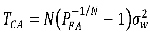

- Because all parameters are constant (apart from the random variables MNc and


- To find a solution for β that will allow the original TCA to be scaled such that the PFA is constant when applied to the coherently integrated data, both sides of the argument are divided by


- As will be noted, the term


- Solving the integral, Equation (20) becomes:

- Finally, the closed form solution of the scaling factor β (Equation (29)) may be found with the following sequence of calculations:


- As seen from Equation (29), the scaling factor β estimate is computed for a given set of parameters, including Probability of false alarm (PFA ), Window Size (N), and Number of Channels (Nc). As a result, the threshold computation module 59C may be configured to compute a new or scaled CFAR threshold


- In selected embodiments, the scaling factor parameter β may be computed offline and can be included in αCA , thereby adding no numerical complexity to the CFAR algorithm.
- For OS-CFAR algorithms, the scaling factor parameter β is computed in the same way using Equation (28). In such embodiments, the threshold computation module 59C may be configured to compute a new or scaled OS-CFAR threshold


- For an improved contextual understanding of selected embodiments of the present disclosure, reference is now made to
Figures 6-9 which depict different range profiles illustrating the application of CA-CFAR thresholds for detecting multiple targets, including closely spaced high SNR and low SNR targets. In the example range profiles, there are four targets located atdistance samples 101, 513, 610 and 630, with a high SNR target (at distance sample 610) being closely located next to the lower SNR target (at distance sample 610). The example range profiles were simulated based on a the following parameter values, PFA = 0.001, Window Size (N) = 32, and Number of Channels (Nc) = 192. - Turning first to
Figure 6 , there is depicted an example powerspectrum range profile 60 for a single receiver channel having a specified probability of false alarm (e.g., PFA = 10-3) where a computed CA-CFAR threshold 62 is applied to a range-compressedinput signal 61 for detecting multiple targets, including closely spaced high SNR and low SNR targets. The powerspectrum range profile 60 represents the original noise floor, and the CFAR algorithm computes the CA-CFAR threshold 62 as the product of (1) a pre-computed scaling factor that depends on the desired probability of false alarm PFA and the assumed noise distribution, and (2) the estimated noisevariance 
spectrum range profile 60, the range-compressedinput signal 61 is generated as |X(ω)|2 = |F{x(t)}|2 to be the squared magnitude of the Fourier transform of the digital time domain signal (x(t)) that is output from the receiver channel. Since the CFAR algorithm generally assumes an exponential distribution of the range-compressedinput signal 61, the variance of the noise is proportional to the average value of theinput signal 61, and therefore has a relatively large and "wiggly" variation. As a result of the large variance, the computed CA-CFAR threshold 62 correctly detects certain high SNR target peaks (e.g., 64-65), but masks and fails to detect certain low SNR target peaks (e.g., 63, 66). In addition, there is a non-zero probability of a false detection associated with application of the computed CA-CFAR threshold 62 to the powerspectrum input signal 61, as indicated with thefalse detection 67 that is cause when a noise sample is detected. - Turning now to
Figure 7 , there is depicted anexample range profile 70 where a computed CA-CFAR threshold 72 is applied to a coherently integrated range-compressedinput signal 21 for detecting multiple targets, including closely spaced high SNR and low SNR targets. As depicted in the coherently integrated powerspectrum range profile 70, theinput signal 71 is generated as MNc (ωn ) = max{|F{X(ωn )}/Nc )|2} to be the maximum value selected from the squared magnitude of the Fourier transform of the frequency domain signal (X(ωn )) divided by the number of channels Nc. As a result of the coherent integration processing, the SNR is increased for targets atdistance samples 101, 513, 610 and 630. In addition to reducing the variance of the coherently integrated range-compressedinput signal 71, the effective noise floor for which the probability of false alarm is calculated is reduced by 10log10(β). As a result, the computed CA-CFAR threshold 72 can detect three of the target peaks 73-75, but not thelower SNR peak 76 that is close to thehigh SNR peak 75. - Turning now to
Figure 8 , there is depicted anexample range profile 80 where a computed CA-CFAR threshold 82 is applied to a non-coherently integrated range-compressedinput signal 81 for detecting multiple targets, including closely spaced high SNR and low SNR targets. As depicted in the non-coherently integrated powerspectrum range profile 80, theinput signal 81 is generated as
distance samples 101, 513, 610 and 630. However, the variance of thenoise 81 is reduced which may be viewed as an artificial increase in SNR. As a result, the computed CA-CFAR threshold 82 can detect two of the target peaks 84-85, but not thelower SNR peak 83 that is masked by the CA-CFAR threshold 82 or thelower SNR peak 86 that is close to thehigh SNR peak 85. - Turning now to
Figure 9 , there is depicted anexample range profile 90 for a scaled CA-CFAR threshold 92 that is applied to a coherently integrated range-compressed input signal 91 for detecting multiple targets, including closely spaced high SNR and low SNR targets. As disclosed herein, the input signal 91 is generated as MNc (ωn ) = max{|F{X(ωn )}/Nc )|2} to be the maximum value selected from the normalized squared magnitude of the Fourier transform of the frequency domain signal (X(ωn )), where the normalization factor is the number of channels Nc. In addition, the CFAR algorithm computes and applies the scaled CA-CFAR threshold 92 by first calculating a CFAR threshold TCA from the non-coherent integration data, and then applying a scaling factor
CFAR threshold 92 is applied to coherently integrated range-compressed input signal 91 to distinguish all four peaks 93-96 generated by targets from the peaks generated by the input signal noise 91. As a result of using coherent integration data, the SNR for the targets 93-94 is increased. In addition, both the average value and variance of the coherently integrated range-compressed input signal 91 is reduced. Finally, the scaled CA-CFAR threshold 92 is computed in a way that is less affected by the presence of high SNR targets to more closely fit the input signal 91 so that all four target peaks 93-96 are detected while maintaining the desired probability of false alarm PFA. In addition, there is a non-zero probability of a false detection associated with application of the computed CA-CFAR threshold 92 to the power spectrum input signal 91, as indicated with thefalse detection 97 that is caused when a noise sample is identified as a detection. - To provide additional details for an improved understanding of selected embodiments of the present disclosure, reference is now made to
Figure 10 which illustrates a simplified architectural block diagram of amicrocontroller 100 for automotive and industrial high-performance radar applications which may implement the disclosed system, apparatus, and methodology for detecting one or more targets with a cell average-constant false alarm rate detector. An example implementation, the microcontroller may be implemented with the NXP S32R45 radar MPU which provides high performance imaging radar as a 32-bit automotive radar microprocessor unit (MPU) based on DSP, Arm® Cortex®, and FFT accelerator cores within a single chip. - As depicted, the
microcontroller 100 includes one or more control processor or central processing unit (CPU)subsystems 101, on-chip memory 102 (e.g., volatile or nonvolatile memory), andradar processing platform 103 for providing radar-specific high throughput signal processing. For example, theradar processing platform 103 may include one or more digital signal processor (DSP)cores 103A, one or more radarprocessing hardware accelerators 103B, a data RAM 103C, achirp generator 103D, and atransceiver interface 103E to provide transmit and receive module control and processing. The processor(s) 101, on-chip memory 102, andradar processing platform 103 may be connected over an on-chip interconnect 104 to amemory interface 105, (e.g., DDR interface), one or more connectivity modules 106 (e.g., PCIe 2x, FlexPWM, eTimer, IIC, DSPI, etc.), andother modules 107. In selected embodiments, themicrocontroller 100 may be implemented as circuitry on a single integrated circuit or system-on-chip (SoC). In addition, theinterconnect 104 can be any type of bus structure, including but not limited to a non-coherent interconnect, an advanced high-performance bus (AHB), or an advanced peripheral bus (APB). In addition, the control processor(s) 101 may be any type of processing circuit, including but not limited to a microprocessor (MPU), microcontroller (MCU), digital signal processor (DSP), or another type of processor or processor core with multiple levels of cache memory. Though not shown, themicrocontroller 100 may include peripheral devices or special-purpose processors, communication interfaces, timers, encoders/decoders, and one or more external memory interfaces, such as DDR interface or flash interface. In turn, the external memory interfaces may be connected to external memory, such as DDR memory or flash memory. - As disclosed, the
microcontroller 100 may use the control processor(s) 101 to provide a signal processing toolbox (SPT) which receives digital output signals from theradar processing platform 103 which uses themodules 103A-E to process received radar return signals by applying signal conditioning (e.g., low noise amplification, low/high pass filtering, and analog-to-digital conversion) and signal analysis (e.g., gain, windowing, FFT, and filtering). The resulting digital output signals are then processed by the control processor(s) 101 for detection and tracking to detect one or more targets. In particular, the control processor(s) may execute control code instructions for a CA-CFAR log detector algorithm which processes range and/or doppler compressed RDM data in parallel with both coherent and non-coherent integration processes. In selected embodiments, the control code instructions for a CA-CFAR log detector algorithm may be executed by theDSP core 103A to process the range and/or doppler compressed RDM data with a non-coherently combining process to generate non-coherently integrated data that is used to estimate an extremely precise CFAR threshold by calculating a CFAR threshold TCA or Tos from the non-coherent integration data, and then applying a scaling factor
processing hardware accelerators 103B may process the range and/or doppler compressed RDM data with a coherently combining process to generate coherently integrated data. In addition, the control code instructions for a CA-CFAR log detector algorithm may be executed by the control processor(s) 101 and/orDSP core 103A to apply the scaled CFAR threshold TCA' or Tos' to the coherently integrated data by comparing each cell under test with the corresponding scaled CFAR threshold TCA' or Tos' threshold to detect targets from any input data that exceeds the CA-CFAR or OS-CFAR threshold, respectively, thereby maximizing the probability of detection without degrading the probability of false alarm. - By separately processing the coherent combining and the non-coherent in parallel, the
microcontroller 100 maximizes the efficiency CFAR detection processing. In particular, the range/doppler compresseddata 102A may be retrieved as a 3D RDM from thememory 102 for storage in the data RAM 103C. Once loaded in the data RAM 103C, the 3D RDM is processed in parallel by performing non-coherent integration on theDSP core 103A while simultaneously performing coherent integration using the FFT accelerator in the radarprocessing hardware accelerator 103B. The resulting non-coherent integrated data (generated by theDSP core 103A) and the coherent integrated data (generated by theFFT accelerator 103B) may be stored in thememory 102 and/or data RAM 103C as two-dimensional range-doppler matrices 102B where additional CFAR detection processing is performed. Without using the FFT accelerator to perform coherent combining, the CFAR detection processing would be rather slow. - For an improved contextual understanding of selected embodiments of the present disclosure, reference is now made to
Figures 11-14 which depict different range profiles illustrating the application of CFAR thresholds for detecting multiple targets, including three closely spaced high SNR targets. In the example range profiles, there are four targets located atdistance samples - Turning first to
Figure 11 , there is depicted an example powerspectrum range profile 110 for a single receiver channel having a specified probability of false alarm where a computed CA-CFAR threshold 112 is applied to a range-compressedinput signal 111 for detecting multiple targets, including three closely spaced high SNR targets. As depicted in the example powerspectrum range profile 110, the range-compressedinput signal 111 is generated as |X(ω)|2 = |F{x(t)}|2 to be the squared magnitude of the Fourier transform of the digital time domain signal (x(t)) that is output from the receiver channel. Since the CFAR algorithm generally assumes an exponential distribution of the range-compressedinput signal 111, the variance of the noise is proportional to the average value of theinput signal 111, and therefore has a relatively large and "wiggly" variance. As a result of the large variance, the computed CA-CFAR threshold 112 correctly detects certain high SNR target peaks (e.g., 114, 116), but masks and fails to detect certain low SNR target peaks (e.g., 113, 115). - Turning now to
Figure 12 , there is depicted anexample range profile 120 where a computed CA-CFAR threshold 122 is applied to a coherently integrated range-compressedinput signal 121 for detecting multiple targets, including three closely spaced high SNR targets. As depicted in the coherently integrated powerspectrum range profile 120, theinput signal 121 is generated as MNc (ωn ) = max{|F{X(ωn )}/Nc )|2} to be the maximum value selected from the normalized squared magnitude of the Fourier transform of the frequency domain signal (X(ωn )), where the normalization factor is the number of channels Nc. As a result of the coherent integration processing, the SNR is increased for targets atdistance samples noise 121, the coherent integration or combining reduces the noise floor by 10log10(β). As a result, the computed CA-CFAR threshold 122 can detect three of the target peaks 123, 125, and 126, but not thelower SNR peak 124 that is close to the high SNR peaks 123, 125. - Turning now to
Figure 13 , there is depicted anexample range profile 130 where a computed CA-CFAR threshold 132 is applied to a non-coherently integrated range-compressedinput signal 131 for detecting multiple targets, including three closely spaced high SNR targets. As depicted in the non-coherently integrated powerspectrum range profile 130, theinput signal 131 is generated as
input signal 131 is reduced. As a result, the computed CA-CFAR threshold 132 can detect two of the target peaks 135, 136, but not the twolower SNR peak high SNR peak 135 and masked by the CA-CFAR threshold 132. - Turning now to
Figure 14 , there is depicted anexample range profile 140 for a scaled CA-CFAR threshold 142 that is applied to a coherently integrated range-compressedinput signal 141 for detecting multiple targets, including three closely spaced high SNR targets. As disclosed herein, theinput signal 141 is generated as MNc ((ωn ) = max{|F{X(ωn )}/Nc )|2} to be the maximum value selected from the squared magnitude of the Fourier transform of the frequency domain signal (X(ωn )) divided by the number of channels Nc. In addition, the CFAR algorithm computes and applies the scaled CA-CFAR threshold 142 by first calculating a CFAR threshold TCA from the non-coherent integration data, and then applying a scaling factor β =
- CA-
CFAR threshold 142 is applied to coherently integrated range-compressedinput signal 141 to distinguish all four peaks 143-146 generated by targets from the peaks generated by theinput signal noise 141. As a result of using coherent integration data, the SNR for the targets 143-146is increased. In addition, both the average value and variance of the coherently integrated range-compressedinput signal 141 is reduced. Finally, the scaled CA-CFAR threshold 142 is computed in a way that is less affected by the presence of high SNR targets to more closely fit theinput signal 141 so that all four target peaks 143-146 are detected while maintaining the desired probability of false alarm PFA. In addition, there is a non-zero probability of a false detection associated with application of the computed CA-CFAR threshold 142 to the powerspectrum input signal 141, as indicated with thefalse detection 147 that is cause when a noise sample is detected. - Turning now to
Figures 15-16 , there are graphically depictions of probability of false alarm measurements as a function of the number of receive channels Nc for different expected probability of false alarm values. In particular,Figure 15 depicts the measured probability offalse alarm P FA 151 on a sample set of 104 Monte-Carlo simulations where only noise is present for different values of Nc between 8 and 192 when the expected PFA value was set to 0.001. In addition,Figure 16 depicts the measured probability offalse alarm P FA 161 on a sample set of 104 Monte-Carlo simulations where only noise is present for different values of Nc between 8 and 192 when the expected PFA value was set to .0001. As depicted, the true PPA for values below 192 converges towards twice the expected PFA value. Since this effect is independent of the expected PFA value, one may simply use a PFA half as large to obtain the desired PFA. - Though selected embodiments of the CFAR detector are described herein with reference to using a square-law detector, it will be appreciated that the disclosed combination of non-coherent and coherent integration may also be applied with log-detector systems. As will be appreciated, Equation 33 (below) that is used to develop the log-detector CA-CFAR no longer holds true, as zn are no longer drawn from an exponential distribution:

- If zn are samples of the Power Spectral Density, obtained via non-coherent combining, and one assumes that all zn samples are noise, then all zn are equal among each other and equal to

Equation 33 can be rewritten as:
- From the foregoing, it can be seen that no log-detection correction or scaling is needed when using a log detector if the power spectral density (non-coherent combining) is used to construct the CFAR threshold. As a result, the use of NCC-CI-CFAR together with a log detector provides a number of benefits, such as enhancing multi-target detection capabilities, reducing dynamic range, and SNR boosting.
- To provide additional details for an improved understanding of selected embodiments of the present disclosure, reference is now made to
Figure 17 which illustrates asimplified flow chart 170 showing the logic for using a cell-average CFAR algorithm which computes a scaled threshold from non-coherently integrated power spectrum data for application to coherently integrated power spectrum data. In an example embodiment, the control logic and methodology shown inFigure 17 may be implemented with a combination of hardware and software on a radar controller processor which uses an FFT accelerator to coherently integrate or combine a 3D Range-Doppler-Angle signal into a first 2D RDM signal and also uses processor or microcontroller unit to non-coherently integrate or combine the 3D Range-Doppler-Angle signal into a second 2D RDM signal for implementing a CA-CFAR detector and/or an OS-CFAR detector. Operating under control programming control code, the radar controller processor is configured to execute the cell average-constant false alarm rate detector algorithm for by estimating an extremely precise CFAR threshold based on a low SNR data set that is generated from non-coherently integrated data, and then applying the estimated CFAR threshold to high SNR data that is generated from coherently integrated data, thereby maximizing the probability of detection without degrading the probability of false alarm. - The process starts (step 171), such as when the radar system begins the process of sensing the location and movement of one or more target objects using one or more transmit radar signals that are sent over a plurality of transmit antennas. To generate the transmit radar signals, the radar system first generates a reference chirp signal (step 172), such as by periodically modulating a transmit radar signal with a frequency and/or phase shift. For example, with automotive Frequency Modulation Continuous Wave (FMCW) radars, the reference chirp signal may be generated as a Linear Frequency Modulation (LFM) waveform that is distributed to a plurality of transmit channel circuits which are respectively associated with a plurality of transmit antennas.
- At
step 173, the chirp signals are conditioned and amplified for transmission over the corresponding transmit channel circuits. In selected embodiments, this processing is performed by the transmit channel circuits which each include an RF conditioning module (which filters the chirp signal) and power amplifier (which amplifies the RF conditioning module output for transmission over a corresponding transmit antenna). In embodiments where time-domain modulation is used in combination with the frequency/phase offset modulation, the non-adjacent transmit channel circuits may be controlled to sequentially condition and amplify transmit radar waveforms from non-adjacent transmit antennas. - At
step 174, each physical or virtual receiver channel generates a digital output signals D1 in the time domain x(t) using any suitable sequence of associated to each physical/virtual receiver. For example, each receiver channel may receive and amplify the reflected reference chirp signals from the different transmit channels at a receiveprocessing step 175. In selected embodiments, one or more receive antennas at the receiver module receive target returns from the transmitted reference chirp signal waveforms as (radio frequency) antenna signals for subsequent amplification, such as by using a low noise amplifier to generate an amplified RF signal from the target returns. - In addition, each receiver channel may mix the amplified transmit channel signals with the reference chirp signal at the receiver at
receiver mixing step 176 to generate an intermediate frequency (IF) signal. In selected embodiments, the mixing step may be implemented by applying the reference chirp signal to a receiver module mixer which is also connected to receive the amplified transmit channel signals for mixing with the reference chirp signal, thereby generating an intermediate frequency signal. - In addition, each receiver channel may condition the intermediate frequency signal for digital conversion at
conditioning step 177. In selected embodiments, the conditioning process includes at least feeding the intermediate frequency signal to a bandpass-pass filter, alone or in combination with additional programmable gain and/or filtering steps, thereby generating a bandpass-filtered signal. - In addition, each receiver channel may digitize the bandpass-filtered conditioned IF signal at
ADC step 178, such as by using a high-speed analog/digital converter (ADC) to generate a digital signal output that is suitable for digital processing. Because the maximum unambiguous range extent for each frequency offset reference chirp signal is inversely related to the fast-time sampling interval, the ADC has a high sampling rate. - At the radar controller, the digital signal outputs from the receiver channel(s) are acquired and digitally processed at
step 179 to generate a range compressed signal where the reflected transmit channel signals are separated in the fast-time FFT or range domain. And atstep 180, additional digital processing is applied to generate a Doppler compressed signal where the reflected transmit channel signals are separated in the slow-time FFT or Doppler domain. While any suitable radar signal processing steps may be used, each radar may be configured to perform fast-time FFT and slow-time FFT processing on the received radar signal to derive range and Doppler information. In the fast-time FFT processing, the frequency offset modulation of the reference chirp signals sent over the N transmission channels enables the spectrum to be divided into N consecutive segments with each being associated with a corresponding transmitter. Because the transmitters are separated or divided in the range domain and the waveform is based on LFM, the approach can also be referred to as the LFM range-division (RD) MIMO approach. Based on the range-spectrum division arrangement, the fast-time samples associated with distinct transmitters are then recovered (and whose sum and delta components are coherently summed for the case of I-channel only FOM,) and the subsequent MIMO virtual array processing can be carried out. - At
step 181, the radar controller assembles a three-dimensional Range-Doppler-Angle signal or cube based on the previous receiver channel processing steps. As described herein, the 3D Range-Doppler-Angle signal has range-doppler-angle dimensions, where each entry in the angular dimension corresponds to a receiver channel for a total of Nc entries. - At steps 182-185, the 3D Range-Doppler-Angle (RDA) signal is supplied in parallel to separate CFAR phased array pre-processing modules which are used to identify range-Doppler peak detections for use in estimating the direction of arrival for the target return(s). In a first pre-processing module or step 182, coherent integration of all RDAs in the angular domain is performed on the 3D Range-Doppler-Angle signal. In selected embodiments, the coherent integration or combining
step 182 may be implemented with an FFT accelerator which implements matched filtering in the spatial domain (among receive channels) and applies a global maximum function on the absolute values of the matching filter's output. At the first processing module or step 182, the input data is the 3D RDM signal or radar cube, and the output is a first two-dimensional RDM of coherently integrated data. - In a second pre-processing module or step 183, non-coherent integration is performed of all RDAs in the angular domain of the 3D Range-Doppler-Angle. In selected embodiments, the non-coherent integration or combining
step 183 may be implemented with a processor core which computes an average of the squared absolute values of the samples in the spatial domain (among receive channels). At the second processing module or step 183, the input data is the 3D Range-Doppler-Angle signal or radar cube, and the output is a second two-dimensional RDM of non-coherently integrated data. - At
step 184, a scaled CFAR threshold TCFAR' = βTCFAR is computed for each log detector sample value. In selected CA-CFAR embodiments, the threshold computation processing may compute or retrieve a predetermined scaling or mapping factor β having a closed form solution, such as

- In selected OS-CFAR embodiments, the threshold
computation processing step 184 may compute or retrieve a predetermined scaling or mapping factor β having a closed form solution, such as
- At
step 185, the coherently integrated data (from step 182) is compared to the scaled threshold TCFAR' (from step 184) to identify target detections. For example, a log detector sample value for the cell under test (λCUT) is compared to the scaled threshold TCFAR' for purposes of identifying target detections when λCUT>TCFAR'. The processing atstep 185 is repeated until all log detector sample values have been evaluated as a cell under test, such as by detecting if the last cell under test has been reached. - When the last cell under test is processed, then the processing proceeds to step 186 where the target detections identified by the CFAR algorithm processing steps 182-185 are combined to obtain the range-Doppler peak detections. At
step 187, the combined target detections are processed to estimate the direction of arrival before continuing with spatial angle estimation processing, target tracking processing, and measurement processing (step 188), with the result being output to other automotive computing or user interfacing devices for further process or display. - A vehicle radar system, apparatus and method use a radar control processing unit generate compressed radar data signals, to apply the compressed radar data signals in parallel as a three-dimensional matrix to a coherent integrator (which generates a two-dimensional matrix of coherently integrated image data) and a non-coherent integrator (which generates a two-dimensional matrix of non-coherently integrated image data), and to generate a constant false alarm rate (CFAR) threshold from the two-dimensional matrix of non-coherently integrated image data for application to the two-dimensional matrix of coherently integrated image data to detect one or more targets in the MIMO radar signal returns from sample values from the two-dimensional matrix of coherently integrated image data that exceed the CFAR threshold.
- As disclosed herein, a vehicle radar system, apparatus and method use a radar control processing unit to apply CFAR phased array pre-processing to compressed radar data signals by using a constant false alarm rate (CFAR) detector which non-coherently integrates the compressed radar data signals into sample values of a first RDM and which coherently integrates the compressed radar data signals into sample values of a second RDM which are used to compute a scaled CFAR threshold that is applied to the coherently integrated sample values of the first RDM data. As disclosed herein, the compressed radar data signals may be generated as three-dimensional Range-Doppler Matrices or Synthetic Aperture Radar Images, and the first and second RDMs may each be generated as two-dimensional matrices. In addition, the scaled CFAR threshold may be computed by multiplying a CA-CFAR threshold (or an OS-CFAR threshold) by the computed CFAR scaling factor β.
- By now it should be appreciated that there has been provided a radar system, device, and method for computing a constant false alarm rate (CFAR) threshold with a radar control processing unit. The disclosed radar system includes a radio-frequency (RF) transmitter unit and first plurality of transmit antennas which are connected and controlled by the radar control processing unit to transmit MIMO radar signals. The disclosed radar system also includes an RF receiver unit and a first plurality of receive antennas which are connected and controlled by the radar control processing unit to generate digital output signals from MIMO radar signal returns received in response to the MIMO radar signals. The disclosed radar control processing unit is configured as a constant false alarm rate (CFAR) detector to generate compressed radar data signals from the digital output signals. In selected embodiments, the compressed radar data signals are generated as an n dimensional matrix (e.g., integer value n=3) of range and/or Doppler compressed image data. In selected embodiments, the radar control processing unit may be configured as a CFAR square-law detector or a CFAR log detector. The compressed radar data signals are applied in parallel as an n dimensional matrix to a coherent integrator and a non-coherent integrator. As disclosed, the coherent integrator generates an n-1 dimensional matrix of coherently integrated image data from the compressed radar data signals. In addition, the non-coherent integrator generates an n-1 dimensional matrix of non-coherently integrated image data from the compressed radar data signals. In selected embodiments, the coherent integrator uses a fast Fourier transform (FFT) accelerator to generate the n-1 dimensional matrix of coherently integrated image data, and the non-coherent integrator uses a processor core to generate a n-1 dimensional matrix of non-coherently integrated image data. In other embodiments, the coherent integrator may be configured to generate the n-1 dimensional matrix of coherently integrated image data by performing a matched filtering process in a spatial domain of the n dimensional matrix of compressed radar data signals and applying a global maximum on absolute values of output data from the matched filtering process. In addition, the non-coherent integrator may be configured to generate the n-1 dimensional matrix of non-coherently integrated image data by computing an average of squared absolute values of the samples in a spatial domain of the n dimensional matrix of compressed radar data signals. In addition, the disclosed radar control processing unit is configured to generate a CFAR threshold from the n-1 dimensional matrix of non-coherently integrated image data. In addition, the disclosed radar control processing unit is configured to detect one or more targets in the MIMO radar signal returns by applying the CFAR threshold to the n-1 dimensional matrix of coherently integrated image data to detect sample values from the n-1 dimensional matrix of coherently integrated image data that exceed the CFAR threshold. In selected embodiments, the radar control processing unit is configured to generate the CFAR threshold by computing an ordered statistics CFAR (OS-CFAR) threshold as a product of a predetermined scaling factor β =


- In another form, there is provided a method for operating a radar system and device wherein a CFAR threshold is computed and used to detect targets. In the disclosed methodology, MIMO radar signals are transmitted from transit antennas in a plurality of transmit and receive antennas, and MIMO radar signal returns are received at receive antennas in the plurality of transmit and receive antennas. In addition, the MIMO radar signal returns are processed with a plurality of receive channels to generate compressed radar data signals as a three-dimensional matrix that are supplied in parallel to a coherent integrator and a non-coherent integrator in a CFAR detector. In selected embodiments, the MIMO radar signal returns are processed to generate the compressed radar data signals as a three-dimensional matrix of range and Doppler compressed image data. The disclosed methodology also coherently combines the compressed radar data signals at the coherent integrator to generate a two-dimensional matrix of coherently integrated image data from the compressed radar data signals. In addition, the disclosed methodology non-coherently combines the compressed radar data signals at the non-coherent integrator to generate a two-dimensional matrix of non-coherently integrated image data from the compressed radar data signals. The disclosed methodology also generates a CFAR threshold from the two-dimensional matrix of non-coherently integrated image data. In selected embodiments, the CFAR threshold is generated by computing an ordered statistics CFAR (OS-CFAR) threshold as a product of a predetermined scaling factor


- In yet another form, there is provided a radar apparatus and associated method of operation. In the disclosed radar apparatus, a transmitter is configured to transmit a first transmit signal and a second transmit signal. The radar apparatus also includes a receiver that is configured to produce digital output signals from first and second transmit signal returns received in response to the first and second transmit signals. In addition, the radar apparatus includes a digital signal processor configured to process the digital output signals with a CFAR detector. To this end, the digital signal processor is configured to generate, from the digital output signals, range and Doppler compressed radar data signals as an ndimensional matrix (e.g., integer value n=3) of compressed image data. In addition, the digital signal processor is configured to coherently combine the range and Doppler compressed radar data signals at the CFAR detector to generate an n-1 dimensional matrix of coherently integrated image data from the range and Doppler compressed radar data signals. In addition, the digital signal processor is configured to non-coherently combine the range and Doppler compressed radar data signals at the CFAR detector to generate an n-1 dimensional matrix of non-coherently integrated image data from the compressed radar data signals. In selected embodiments, the CFAR detector may use a fast Fourier transform (FFT) accelerator to generate the n-1 dimensional matrix of coherently integrated image data, and may use a processor core to generate a n-1 dimensional matrix of non-coherently integrated image data. In selected embodiments, the digital signal processor may be configured to coherently combine the range and Doppler compressed radar data signals by performing a matched filtering process in a spatial domain of the n dimensional matrix of compressed radar data signals and applying a global maximum on absolute values of output data from the matched filtering process. In addition, the digital signal processor may be configured to non-coherently combine the range and Doppler compressed radar data signals by computing an average of squared absolute values of the samples in a spatial domain of the n dimensional matrix of compressed radar data signals. In addition, the digital signal processor is configured to generate a CFAR threshold from the n-1 dimensional matrix of non-coherently integrated image data, and to apply the CFAR threshold to the n-1 dimensional matrix of coherently integrated image data to detect sample values from the n-1 dimensional matrix of coherently integrated image data that exceed the CFAR threshold, thereby identifying one or more targets in the MIMO radar signal returns. In selected embodiments, the CFAR detector may be a square-law detector or a log detector or other suitable CFAR detector.
- Although the described exemplary embodiments disclosed herein focus on example automotive radar circuits, systems, and methods for using same, the present invention is not necessarily limited to the example embodiments illustrate herein. For example, various embodiments of a distributed aperture radar may be applied in non-automotive applications, and may use additional or fewer circuit components than those specifically set forth. Thus, the particular embodiments disclosed above are illustrative only and should not be taken as limitations upon the present invention, as the invention may be modified and practiced in different but equivalent manners apparent to those skilled in the art having the benefit of the teachings herein. Accordingly, the foregoing description is not intended to limit the invention to the particular form set forth, but on the contrary, is intended to cover such alternatives, modifications and equivalents as may be included within the spirit and scope of the invention as defined by the appended claims so that those skilled in the art should understand that they can make various changes, substitutions and alterations without departing from the spirit and scope of the invention in its broadest form.
- Benefits, other advantages, and solutions to problems have been described above with regard to specific embodiments. However, the benefits, advantages, solutions to problems, and any element(s) that may cause any benefit, advantage, or solution to occur or become more pronounced are not to be construed as a critical, required, or essential feature or element of any or all the claims. As used herein, the terms "comprises," "comprising," or any other variation thereof, are intended to cover a non-exclusive inclusion, such that a process, method, article, or apparatus that comprises a list of elements does not include only those elements but may include other elements not expressly listed or inherent to such process, method, article, or apparatus.
Claims (15)
- A radar system, comprising:a radio-frequency (RF) transmitter unit and first plurality of transmit antennas which are connected to transmit MIMO radar signals;an RF receiver unit and a first plurality of receive antennas which are connected to generate digital output signals from MIMO radar signal returns received in response to the MIMO radar signals; anda radar control processing unit connected and configured to control the RF transmitter unit and the RF receiver unit;wherein the radar control processing unit is configured as a constant false alarm rate (CFAR) detector to generate, from the digital output signals, compressed radar data signals that are applied in parallel as an n dimensional matrix to:a coherent integrator which generates an n-1 dimensional matrix of coherently integrated image data from the compressed radar data signals, anda non-coherent integrator which generates an n-1 dimensional matrix of non-coherently integrated image data from the compressed radar data signals;wherein the radar control processing unit is further configured to generate a CFAR threshold from the n-1 dimensional matrix of non-coherently integrated image data; andwherein the radar control processing unit is further configured to detect one or more targets in the MIMO radar signal returns by applying the CFAR threshold to the n-1 dimensional matrix of coherently integrated image data to detect sample values from the n-1 dimensional matrix of coherently integrated image data that exceed the CFAR threshold.
- The radar system of claim 1, wherein the radar control processing unit is configured to generate the CFAR threshold by computing an ordered statistics CFAR (OS-CFAR) threshold as a product of a predetermined scaling factor

- The radar system of any preceding claim, wherein the radar control processing unit is configured to generate the CFAR threshold by computing a cell-average CFAR (CA-CFAR) threshold as a product of a predetermined scaling factor


- The radar system of any preceding claim, wherein the radar control processing unit is further configured to generate the compressed radar data signals as an n dimensional matrix of range and Doppler compressed image data.
- The radar system of any preceding claim, wherein the coherent integrator uses a fast Fourier transform (FFT) accelerator to generate the n-1 dimensional matrix of coherently integrated image data, and wherein the non-coherent integrator uses a processor core to generate a n-1 dimensional matrix of non-coherently integrated image data.
- The radar system of claim 5, wherein the coherent integrator is configured to generate the n-1 dimensional matrix of coherently integrated image data by performing a matched filtering process in a spatial domain of the n dimensional matrix of compressed radar data signals and applying a global maximum on absolute values of output data from the matched filtering process.
- The radar system of any of claims 5 or 6, wherein the non-coherent integrator is configured to generate the n-1 dimensional matrix of non-coherently integrated image data by computing an average of squared absolute values of the samples in a spatial domain of the n dimensional matrix of compressed radar data signals.
- The radar system of any preceding claim, wherein the radar control processing unit is configured as a CFAR square-law detector.
- The radar system of any preceding claim, wherein the radar control processing unit is configured as a CFAR log detector.
- A method for operating a radar system, comprising:transmitting MIMO radar signals from transit antennas in a plurality of transmit and receive antennas;receiving MIMO radar signal returns at receive antennas in the plurality of transmit and receive antennas;processing the MIMO radar signal returns with a plurality of receive channels to generate compressed radar data signals as a three-dimensional matrix;supplying the compressed radar data signals in parallel to a coherent integrator and a non-coherent integrator in a constant false alarm rate (CFAR) detector;coherently combining the compressed radar data signals at the coherent integrator to generate a two-dimensional matrix of coherently integrated image data from the compressed radar data signals;non-coherently combining the compressed radar data signals at the non-coherent integrator to generate a two-dimensional matrix of non-coherently integrated image data from the compressed radar data signals;generating a CFAR threshold from the two-dimensional matrix of non-coherently integrated image data; andapplying the CFAR threshold to the two-dimensional matrix of coherently integrated image data to detect sample values from the two-dimensional matrix of coherently integrated image data that exceed the CFAR threshold, thereby identifying one or more targets in the MIMO radar signal returns.
- The method of claim 10, wherein generating the CFAR threshold comprises computing an ordered statistics CFAR (OS-CFAR) threshold as a product of a predetermined scaling factor

- The method of any of claims 10 or 11, wherein generating the CFAR threshold comprises computing a cell-average CFAR (CA-CFAR) threshold as a product of a predetermined scaling factor

- The method of any of claims 10 to 12, wherein processing the MIMO radar signal returns comprises generating the compressed radar data signals as a three-dimensional matrix of range and Doppler compressed image data.
- The method of claim 13, wherein coherently combining the compressed radar data signals comprises using a fast Fourier transform (FFT) accelerator to compress the three-dimensional matrix of range and Doppler compressed image data into the two-dimensional matrix of coherently integrated image data, and wherein non-coherently combining the compressed radar data signals comprises using a processor core to compress the three-dimensional matrix of range and Doppler compressed image data into the two-dimensional matrix of non-coherently integrated image data.
- The method of claim 14, wherein coherently combining the compressed radar data signals comprises performing a matched filtering process in a spatial domain of the three-dimensional matrix of compressed radar data signals and applying a global maximum on absolute values of output data from the matched filtering process.
Applications Claiming Priority (1)
| Application Number | Priority Date | Filing Date | Title |
|---|---|---|---|
| RO202100722 | 2021-11-26 |
Publications (2)
| Publication Number | Publication Date |
|---|---|
| EP4187275A1 true EP4187275A1 (en) | 2023-05-31 |
| EP4187275B1 EP4187275B1 (en) | 2026-02-18 |
Family
ID=84246023
Family Applications (1)
| Application Number | Title | Priority Date | Filing Date |
|---|---|---|---|
| EP22205618.6A Active EP4187275B1 (en) | 2021-11-26 | 2022-11-04 | Cfar phased array pre-processing using noncoherent and coherent integration in automotive radar systems |
Country Status (2)
| Country | Link |
|---|---|
| US (1) | US12189025B2 (en) |
| EP (1) | EP4187275B1 (en) |
Cited By (4)
| Publication number | Priority date | Publication date | Assignee | Title |
|---|---|---|---|---|
| CN116626646A (en) * | 2023-07-21 | 2023-08-22 | 西安电子科技大学 | Meshless Loss Coherent Accumulation Method for Radar Targets Based on Time-Frequency Non-Uniform Sampling |
| CN117079245A (en) * | 2023-07-05 | 2023-11-17 | 浙江工业大学 | A method of identifying traffic road targets based on wireless signals |
| CN119270224A (en) * | 2024-10-29 | 2025-01-07 | 电子科技大学 | A distributed coherent MIMO radar multi-channel multi-frame signal accumulation detection method |
| EP4624978A1 (en) * | 2024-03-27 | 2025-10-01 | Volkswagen Ag | A method for determining a target information of a radar target based on an incoherent signal processing chain, radar system and motor vehicle |
Families Citing this family (12)
| Publication number | Priority date | Publication date | Assignee | Title |
|---|---|---|---|---|
| DE102022210263A1 (en) * | 2022-09-28 | 2024-03-28 | Robert Bosch Gesellschaft mit beschränkter Haftung | Method for controlling a coherent cooperative radar sensor network |
| US12388697B2 (en) * | 2023-02-06 | 2025-08-12 | Raytheon Company | Radio frequency interference mitigation in weather sensing |
| CN117452329B (en) * | 2023-10-25 | 2024-04-02 | 中国人民解放军军事科学院系统工程研究院 | Coherent estimation method and device for target positioning parameters of radiation source |
| CN117686993A (en) * | 2023-11-28 | 2024-03-12 | 北京航空航天大学杭州创新研究院 | Smart toilet human body detection method and device based on millimeter wave radar |
| KR20250091821A (en) * | 2023-12-14 | 2025-06-23 | 삼성전자주식회사 | Storage device, and sensor system and automotive comrpising the same |
| WO2025129424A1 (en) * | 2023-12-19 | 2025-06-26 | Qualcomm Incorporated | Sensing node constant false alarm rate (cfar) configuration for radio frequency (rf) sensing |
| CN117849753B (en) * | 2024-03-07 | 2024-05-03 | 长沙莫之比智能科技有限公司 | A target pan-feature extraction method based on vehicle-borne millimeter-wave radar |
| CN118707488B (en) * | 2024-09-02 | 2025-02-11 | 西安电子科技大学 | A method for coherent processing of multi-base radar received signals |
| CN118915011B (en) * | 2024-09-29 | 2025-03-07 | 哈尔滨工业大学(威海) | Low-complexity super-resolution 3D estimation method based on millimeter wave MIMO radar |
| CN119805398B (en) * | 2024-12-26 | 2026-05-08 | 上海微波设备研究所(中国电子科技集团公司第五十一研究所) | A joint processing method of noncoherent and coherent accumulation based on noncooperative radar with external radiation source |
| CN120103297B (en) * | 2025-05-08 | 2025-07-18 | 中国人民解放军海军航空大学 | Two-dimensional constant false alarm target detection method and detector based on dual observation channel data |
| CN120722305B (en) * | 2025-08-14 | 2025-11-07 | 中国矿业大学 | A method, system, device and medium for long-term coherent accumulation of data for maneuvering targets. |
Family Cites Families (4)
| Publication number | Priority date | Publication date | Assignee | Title |
|---|---|---|---|---|
| US4104633A (en) * | 1977-04-18 | 1978-08-01 | International Telephone And Telegraph Corporation | Extended target-log CFAR processor |
| US5499030A (en) * | 1994-03-18 | 1996-03-12 | The United States Of America As Represented By The Secretary Of The Air Force | Expert system constant false alarm rate (CFAR) processor |
| US7642951B2 (en) * | 2004-11-12 | 2010-01-05 | James Onorato | Dual channel spatially adaptive CFAR |
| CN104502899B (en) * | 2014-12-27 | 2017-11-21 | 长安大学 | A kind of adaptive constant false alarm rate object detection method |
-
2022
- 2022-06-16 US US17/807,279 patent/US12189025B2/en active Active
- 2022-11-04 EP EP22205618.6A patent/EP4187275B1/en active Active
Non-Patent Citations (1)
| Title |
|---|
| LIN YU-CHIEN ET AL: "Low-Complexity High-Resolution Parameter Estimation for Automotive MIMO Radars", IEEE ACCESS, IEEE, USA, vol. 8, 1 July 2019 (2019-07-01), pages 16127 - 16138, XP011768313, DOI: 10.1109/ACCESS.2019.2926413 * |
Cited By (6)
| Publication number | Priority date | Publication date | Assignee | Title |
|---|---|---|---|---|
| CN117079245A (en) * | 2023-07-05 | 2023-11-17 | 浙江工业大学 | A method of identifying traffic road targets based on wireless signals |
| CN117079245B (en) * | 2023-07-05 | 2024-09-17 | 浙江工业大学 | A method for traffic road target recognition based on wireless signals |
| CN116626646A (en) * | 2023-07-21 | 2023-08-22 | 西安电子科技大学 | Meshless Loss Coherent Accumulation Method for Radar Targets Based on Time-Frequency Non-Uniform Sampling |
| CN116626646B (en) * | 2023-07-21 | 2023-09-22 | 西安电子科技大学 | Gridless loss coherent accumulation method for radar targets based on time-frequency non-uniform sampling |
| EP4624978A1 (en) * | 2024-03-27 | 2025-10-01 | Volkswagen Ag | A method for determining a target information of a radar target based on an incoherent signal processing chain, radar system and motor vehicle |
| CN119270224A (en) * | 2024-10-29 | 2025-01-07 | 电子科技大学 | A distributed coherent MIMO radar multi-channel multi-frame signal accumulation detection method |
Also Published As
| Publication number | Publication date |
|---|---|
| US12189025B2 (en) | 2025-01-07 |
| US20230168367A1 (en) | 2023-06-01 |
| EP4187275B1 (en) | 2026-02-18 |
Similar Documents
| Publication | Publication Date | Title |
|---|---|---|
| EP4187275B1 (en) | Cfar phased array pre-processing using noncoherent and coherent integration in automotive radar systems | |
| US10969463B2 (en) | Radar sensing with interference suppression | |
| US11209523B2 (en) | FMCW radar with interference signal rejection | |
| US11016171B2 (en) | Radar sensing with phase correction | |
| US11592520B2 (en) | FMCW radar with interfering signal suppression in the time domain | |
| US11885903B2 (en) | FMCW radar with interference signal suppression using artificial neural network | |
| JP6564472B2 (en) | Vehicle radar system | |
| EP3109662B1 (en) | Radar signal processing for automated vehicles | |
| US11754673B2 (en) | Cell-average and ordered-statistic of cell-average CFAR algorithms for log detectors | |
| US20200124699A1 (en) | Fmcw radar with interference signal suppression | |
| US10234541B2 (en) | FMCW radar device | |
| US10627481B2 (en) | Multi-resolution doppler processing | |
| US11681011B2 (en) | Detection of interference-induced perturbations in FMCW radar systems | |
| Fischer et al. | Robust detection and mitigation of mutual interference in automotive radar | |
| US12050284B2 (en) | Automotive radar with hardware accelerated target detection capability | |
| US20250258272A1 (en) | Radar system and method with interference suppression | |
| Yanovsky et al. | Ultrawideband signal processing algorithms for radars and sodars | |
| US20240280692A1 (en) | Fine-near-range estimation method for automotive radar applications | |
| EP4579280A1 (en) | Radar signal direction of arrival super-resolution estimation | |
| US12085634B2 (en) | Method for capture in a radar system | |
| CN118275999A (en) | Transmitting phase calibration method, device, integrated circuit, radio device and terminal |
Legal Events
| Date | Code | Title | Description |
|---|---|---|---|
| PUAI | Public reference made under article 153(3) epc to a published international application that has entered the european phase |
Free format text: ORIGINAL CODE: 0009012 |
|
| STAA | Information on the status of an ep patent application or granted ep patent |
Free format text: STATUS: THE APPLICATION HAS BEEN PUBLISHED |
|
| AK | Designated contracting states |
Kind code of ref document: A1 Designated state(s): AL AT BE BG CH CY CZ DE DK EE ES FI FR GB GR HR HU IE IS IT LI LT LU LV MC ME MK MT NL NO PL PT RO RS SE SI SK SM TR |
|
| STAA | Information on the status of an ep patent application or granted ep patent |
Free format text: STATUS: REQUEST FOR EXAMINATION WAS MADE |
|
| 17P | Request for examination filed |
Effective date: 20231130 |
|
| RBV | Designated contracting states (corrected) |
Designated state(s): AL AT BE BG CH CY CZ DE DK EE ES FI FR GB GR HR HU IE IS IT LI LT LU LV MC ME MK MT NL NO PL PT RO RS SE SI SK SM TR |
|
| GRAP | Despatch of communication of intention to grant a patent |
Free format text: ORIGINAL CODE: EPIDOSNIGR1 |
|
| STAA | Information on the status of an ep patent application or granted ep patent |
Free format text: STATUS: GRANT OF PATENT IS INTENDED |
|
| INTG | Intention to grant announced |
Effective date: 20251017 |
|
| GRAS | Grant fee paid |
Free format text: ORIGINAL CODE: EPIDOSNIGR3 |
|
| GRAA | (expected) grant |
Free format text: ORIGINAL CODE: 0009210 |
|
| STAA | Information on the status of an ep patent application or granted ep patent |
Free format text: STATUS: THE PATENT HAS BEEN GRANTED |
|
| AK | Designated contracting states |
Kind code of ref document: B1 Designated state(s): AL AT BE BG CH CY CZ DE DK EE ES FI FR GB GR HR HU IE IS IT LI LT LU LV MC ME MK MT NL NO PL PT RO RS SE SI SK SM TR |
|
| REG | Reference to a national code |
Ref country code: CH Ref legal event code: F10 Free format text: ST27 STATUS EVENT CODE: U-0-0-F10-F00 (AS PROVIDED BY THE NATIONAL OFFICE) Effective date: 20260218 Ref country code: GB Ref legal event code: FG4D |
|
| REG | Reference to a national code |
Ref country code: DE Ref legal event code: R096 Ref document number: 602022030524 Country of ref document: DE |
|
| REG | Reference to a national code |
Ref country code: IE Ref legal event code: FG4D |
|
| REG | Reference to a national code |
Ref country code: NL Ref legal event code: MP Effective date: 20260218 |
|
| PG25 | Lapsed in a contracting state [announced via postgrant information from national office to epo] |
Ref country code: RS Free format text: LAPSE BECAUSE OF FAILURE TO SUBMIT A TRANSLATION OF THE DESCRIPTION OR TO PAY THE FEE WITHIN THE PRESCRIBED TIME-LIMIT Effective date: 20260518 |
|
| PG25 | Lapsed in a contracting state [announced via postgrant information from national office to epo] |
Ref country code: ES Free format text: LAPSE BECAUSE OF FAILURE TO SUBMIT A TRANSLATION OF THE DESCRIPTION OR TO PAY THE FEE WITHIN THE PRESCRIBED TIME-LIMIT Effective date: 20260218 |
|
| PG25 | Lapsed in a contracting state [announced via postgrant information from national office to epo] |
Ref country code: PL Free format text: LAPSE BECAUSE OF FAILURE TO SUBMIT A TRANSLATION OF THE DESCRIPTION OR TO PAY THE FEE WITHIN THE PRESCRIBED TIME-LIMIT Effective date: 20260218 |
|
| PG25 | Lapsed in a contracting state [announced via postgrant information from national office to epo] |
Ref country code: GR Free format text: LAPSE BECAUSE OF FAILURE TO SUBMIT A TRANSLATION OF THE DESCRIPTION OR TO PAY THE FEE WITHIN THE PRESCRIBED TIME-LIMIT Effective date: 20260519 |
|
| REG | Reference to a national code |
Ref country code: LT Ref legal event code: MG9D |
|
| PG25 | Lapsed in a contracting state [announced via postgrant information from national office to epo] |
Ref country code: LT Free format text: LAPSE BECAUSE OF FAILURE TO SUBMIT A TRANSLATION OF THE DESCRIPTION OR TO PAY THE FEE WITHIN THE PRESCRIBED TIME-LIMIT Effective date: 20260218 |
|
| PG25 | Lapsed in a contracting state [announced via postgrant information from national office to epo] |
Ref country code: NO Free format text: LAPSE BECAUSE OF FAILURE TO SUBMIT A TRANSLATION OF THE DESCRIPTION OR TO PAY THE FEE WITHIN THE PRESCRIBED TIME-LIMIT Effective date: 20260518 |
|
| PG25 | Lapsed in a contracting state [announced via postgrant information from national office to epo] |
Ref country code: FI Free format text: LAPSE BECAUSE OF FAILURE TO SUBMIT A TRANSLATION OF THE DESCRIPTION OR TO PAY THE FEE WITHIN THE PRESCRIBED TIME-LIMIT Effective date: 20260218 Ref country code: SE Free format text: LAPSE BECAUSE OF FAILURE TO SUBMIT A TRANSLATION OF THE DESCRIPTION OR TO PAY THE FEE WITHIN THE PRESCRIBED TIME-LIMIT Effective date: 20260218 Ref country code: AT Free format text: LAPSE BECAUSE OF FAILURE TO SUBMIT A TRANSLATION OF THE DESCRIPTION OR TO PAY THE FEE WITHIN THE PRESCRIBED TIME-LIMIT Effective date: 20260218 |
|
| REG | Reference to a national code |
Ref country code: AT Ref legal event code: MK05 Ref document number: 1888614 Country of ref document: AT Kind code of ref document: T Effective date: 20260218 |
|
| PG25 | Lapsed in a contracting state [announced via postgrant information from national office to epo] |
Ref country code: HR Free format text: LAPSE BECAUSE OF FAILURE TO SUBMIT A TRANSLATION OF THE DESCRIPTION OR TO PAY THE FEE WITHIN THE PRESCRIBED TIME-LIMIT Effective date: 20260218 |
|
| PG25 | Lapsed in a contracting state [announced via postgrant information from national office to epo] |
Ref country code: IS Free format text: LAPSE BECAUSE OF FAILURE TO SUBMIT A TRANSLATION OF THE DESCRIPTION OR TO PAY THE FEE WITHIN THE PRESCRIBED TIME-LIMIT Effective date: 20260618 Ref country code: PT Free format text: LAPSE BECAUSE OF FAILURE TO SUBMIT A TRANSLATION OF THE DESCRIPTION OR TO PAY THE FEE WITHIN THE PRESCRIBED TIME-LIMIT Effective date: 20260618 |
|
| PG25 | Lapsed in a contracting state [announced via postgrant information from national office to epo] |
Ref country code: NL Free format text: LAPSE BECAUSE OF FAILURE TO SUBMIT A TRANSLATION OF THE DESCRIPTION OR TO PAY THE FEE WITHIN THE PRESCRIBED TIME-LIMIT Effective date: 20260218 |
|
| PG25 | Lapsed in a contracting state [announced via postgrant information from national office to epo] |
Ref country code: LV Free format text: LAPSE BECAUSE OF FAILURE TO SUBMIT A TRANSLATION OF THE DESCRIPTION OR TO PAY THE FEE WITHIN THE PRESCRIBED TIME-LIMIT Effective date: 20260218 |
|
| PG25 | Lapsed in a contracting state [announced via postgrant information from national office to epo] |
Ref country code: BG Free format text: LAPSE BECAUSE OF FAILURE TO SUBMIT A TRANSLATION OF THE DESCRIPTION OR TO PAY THE FEE WITHIN THE PRESCRIBED TIME-LIMIT Effective date: 20260218 |