EP4187256A1 - Anti-corrosive braze coatings for air data probes - Google Patents
Anti-corrosive braze coatings for air data probes Download PDFInfo
- Publication number
- EP4187256A1 EP4187256A1 EP22209319.7A EP22209319A EP4187256A1 EP 4187256 A1 EP4187256 A1 EP 4187256A1 EP 22209319 A EP22209319 A EP 22209319A EP 4187256 A1 EP4187256 A1 EP 4187256A1
- Authority
- EP
- European Patent Office
- Prior art keywords
- air data
- data probe
- orientation
- braze material
- braze
- Prior art date
- Legal status (The legal status is an assumption and is not a legal conclusion. Google has not performed a legal analysis and makes no representation as to the accuracy of the status listed.)
- Pending
Links
- 239000000523 sample Substances 0.000 title claims abstract description 171
- 238000000576 coating method Methods 0.000 title description 2
- 238000010438 heat treatment Methods 0.000 claims abstract description 131
- 239000000463 material Substances 0.000 claims abstract description 123
- 238000005260 corrosion Methods 0.000 claims abstract description 32
- 230000007797 corrosion Effects 0.000 claims abstract description 30
- 238000000034 method Methods 0.000 claims description 61
- 230000005484 gravity Effects 0.000 claims description 15
- 239000002002 slurry Substances 0.000 claims description 13
- 238000001035 drying Methods 0.000 claims description 11
- 238000004519 manufacturing process Methods 0.000 claims description 7
- 230000000873 masking effect Effects 0.000 claims description 7
- 150000001875 compounds Chemical class 0.000 claims description 5
- 239000004568 cement Substances 0.000 claims description 3
- ORQBXQOJMQIAOY-UHFFFAOYSA-N nobelium Chemical compound [No] ORQBXQOJMQIAOY-UHFFFAOYSA-N 0.000 description 19
- 238000005219 brazing Methods 0.000 description 6
- 238000009826 distribution Methods 0.000 description 4
- 238000009825 accumulation Methods 0.000 description 3
- 238000010586 diagram Methods 0.000 description 3
- 230000007613 environmental effect Effects 0.000 description 3
- 239000002184 metal Substances 0.000 description 3
- 229910052751 metal Inorganic materials 0.000 description 3
- 239000007769 metal material Substances 0.000 description 3
- 239000000203 mixture Substances 0.000 description 3
- 239000012255 powdered metal Substances 0.000 description 3
- 239000002904 solvent Substances 0.000 description 3
- 230000003068 static effect Effects 0.000 description 3
- PXHVJJICTQNCMI-UHFFFAOYSA-N Nickel Chemical compound [Ni] PXHVJJICTQNCMI-UHFFFAOYSA-N 0.000 description 2
- 230000004888 barrier function Effects 0.000 description 2
- 230000015572 biosynthetic process Effects 0.000 description 2
- 238000012986 modification Methods 0.000 description 2
- 230000004048 modification Effects 0.000 description 2
- 239000011248 coating agent Substances 0.000 description 1
- 238000010276 construction Methods 0.000 description 1
- 238000001816 cooling Methods 0.000 description 1
- 230000000593 degrading effect Effects 0.000 description 1
- 239000012530 fluid Substances 0.000 description 1
- 238000009434 installation Methods 0.000 description 1
- 238000005259 measurement Methods 0.000 description 1
- 150000002739 metals Chemical class 0.000 description 1
- 239000010445 mica Substances 0.000 description 1
- 229910052618 mica group Inorganic materials 0.000 description 1
- 229910052759 nickel Inorganic materials 0.000 description 1
- 238000013021 overheating Methods 0.000 description 1
- 239000000843 powder Substances 0.000 description 1
Images



Classifications
-
- B—PERFORMING OPERATIONS; TRANSPORTING
- B23—MACHINE TOOLS; METAL-WORKING NOT OTHERWISE PROVIDED FOR
- B23K—SOLDERING OR UNSOLDERING; WELDING; CLADDING OR PLATING BY SOLDERING OR WELDING; CUTTING BY APPLYING HEAT LOCALLY, e.g. FLAME CUTTING; WORKING BY LASER BEAM
- B23K1/00—Soldering, e.g. brazing, or unsoldering
- B23K1/0008—Soldering, e.g. brazing, or unsoldering specially adapted for particular articles or work
-
- B—PERFORMING OPERATIONS; TRANSPORTING
- B64—AIRCRAFT; AVIATION; COSMONAUTICS
- B64D—EQUIPMENT FOR FITTING IN OR TO AIRCRAFT; FLIGHT SUITS; PARACHUTES; ARRANGEMENT OR MOUNTING OF POWER PLANTS OR PROPULSION TRANSMISSIONS IN AIRCRAFT
- B64D15/00—De-icing or preventing icing on exterior surfaces of aircraft
- B64D15/12—De-icing or preventing icing on exterior surfaces of aircraft by electric heating
-
- G—PHYSICS
- G01—MEASURING; TESTING
- G01P—MEASURING LINEAR OR ANGULAR SPEED, ACCELERATION, DECELERATION, OR SHOCK; INDICATING PRESENCE, ABSENCE, OR DIRECTION, OF MOVEMENT
- G01P13/00—Indicating or recording presence, absence, or direction, of movement
- G01P13/02—Indicating direction only, e.g. by weather vane
- G01P13/025—Indicating direction only, e.g. by weather vane indicating air data, i.e. flight variables of an aircraft, e.g. angle of attack, side slip, shear, yaw
-
- G—PHYSICS
- G01—MEASURING; TESTING
- G01P—MEASURING LINEAR OR ANGULAR SPEED, ACCELERATION, DECELERATION, OR SHOCK; INDICATING PRESENCE, ABSENCE, OR DIRECTION, OF MOVEMENT
- G01P5/00—Measuring speed of fluids, e.g. of air stream; Measuring speed of bodies relative to fluids, e.g. of ship, of aircraft
- G01P5/14—Measuring speed of fluids, e.g. of air stream; Measuring speed of bodies relative to fluids, e.g. of ship, of aircraft by measuring differences of pressure in the fluid
- G01P5/16—Measuring speed of fluids, e.g. of air stream; Measuring speed of bodies relative to fluids, e.g. of ship, of aircraft by measuring differences of pressure in the fluid using Pitot tubes, e.g. Machmeter
- G01P5/165—Arrangements or constructions of Pitot tubes
-
- B—PERFORMING OPERATIONS; TRANSPORTING
- B64—AIRCRAFT; AVIATION; COSMONAUTICS
- B64D—EQUIPMENT FOR FITTING IN OR TO AIRCRAFT; FLIGHT SUITS; PARACHUTES; ARRANGEMENT OR MOUNTING OF POWER PLANTS OR PROPULSION TRANSMISSIONS IN AIRCRAFT
- B64D43/00—Arrangements or adaptations of instruments
- B64D43/02—Arrangements or adaptations of instruments for indicating aircraft speed or stalling conditions
Definitions
- the present disclosure relates to air data probes, and more particularly, to air data probes with improved corrosion resistance.
- Air data probe devices can be utilized in, e.g., aerospace applications for measuring environmental parameters usable to determine air data outputs.
- air data probes can measure pitot pressure, static pressure, or other parameters of airflow across the air data probe that are usable for determining air data outputs, such as pressure altitude, altitude rate (e.g., vertical speed), airspeed, Mach number, angle of attack, angle of sideslip, or other air data outputs.
- air data probes often include one or more air data sensing ports, such as static pressure ports located on the side of the probe integral to the surface of the probe that are pneumatically connected to sensors that sense the atmospheric pressure outside of the aircraft. Certain flight conditions can cause ice accumulation within an air data probe, degrading air data probe performance.
- a corrosion-resistant air data probe in one embodiment, includes a hollow tube having at least one opening, an inner surface of the hollow tube defining an interior cavity, a heating element, and a continuous layer of a braze material.
- the heating element is disposed adjacent to the inner surface, within the interior cavity.
- the continuous layer of the braze material completely covers the heating element and covers at least a portion of the inner surface.
- a method of fabricating an air data probe includes applying a braze material to an inner surface of an air data probe, positioning the air data probe in a first orientation relative to a direction of gravity, heating the air data probe while in the first orientation to braze a braze material to the inner surface and a heating coil disposed adjacent to the inner surface, applying additional braze material to the inner surface after heating the air data probe while in the first orientation, positioning the air data probe in a second orientation relative to the direction of gravity, and heating the air data probe while in the second orientation to braze the additional braze material to the inner surface and the heating coil.
- the air data probe comprises a hollow tube having at least one opening, an interior cavity of the hollow tube is defined by the inner surface, and the hollow tube is oriented along an axis. The second orientation is rotated about the axis relative to the first orientation.
- the present disclosure includes systems and methods of for improving corrosion resistance of air data probes. More specifically, the systems and methods disclosed herein use a layer of brazed material to protect heating elements and/or air data probe surfaces from corrosion. The systems and methods disclosed herein advantageously reduce the susceptibility of air data probes to corrosion-based failure.
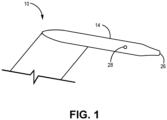
- FIG. 1 is a perspective view of air data probe 10.
- Air data probe 10 includes tube 14 and sensing ports 26 and 28.
- tube 14 includes a barrel- or cylinder-shaped portion and a tapered or conically-shaped section leading to sensing port 28.
- tube 14 can have other suitable geometries.
- Sensing ports 26 and 28 are formed integrally with tube 14 and are pneumatically connected to one or more sensors. Sensing ports 26 and 28 allow air data probe 10 to sense air data when air data probe 10 is placed in a flow or air.
- sensing port 26 is a pitot pressure sensing port and sensing port 28 is a static pressure sensing port.
- air data probe 10 can have other combinations of one or more sensing ports for sensing a variety of air data.
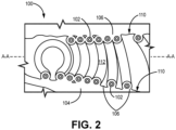
- FIG. 2 is a cross-sectional image of prior art air data probe 100.
- Air data probe 100 has overall structure as disclosed generally with regard to air data probe 10 of FIG. 1 .
- Air data probe 100 includes heating element 102, tube 104, and braze 106.
- Tube 104 includes inner surface 110, which defines cavity 112.
- tube 104 has a hollow conical shape and extends generally along axis A-A.
- tube 104 can be formed into other suitable shapes or combinations of multiple shapes.
- tube 104 can be formed as a hollow cylinder.
- tube 104 can include both cylindrical and conical sections.
- Inner surface 110 defines cavity 112 and forms a channel through which a fluid, such as air, can flow or accumulate.
- tube 104 has one or more openings or ports (not shown) such that air data probe 100 can take in air from a flow of air.
- One or more sensors can be coupled to and/or integrated with tube 104 for measuring air data.
- air data probe 100 is placed in a flow of air to measure air data of the flow of air.
- air data probe 100 can be attached to an aircraft and used to determine one or more of pressure altitude, altitude rate (e.g., vertical speed), airspeed, Mach number, angle of attack, angle of sideslip, air speed, or another suitable air data parameter.
- Heating element 102 is disposed within tube 104 adjacent to inner surface 110 and extends away from inner surface 110 into cavity 112.
- Heating element 102 is a resistive heating element configured to heat inner surface 110 during operation of air data probe 100.
- Heating element 102 is affixed to inner surface 110 by brazing, forming fillets of braze 106 between heating element 102 and inner surface 110.
- the portion of heating element 102 extending away from inner surface 110 is exposed to air in cavity 112.
- heating element 102 has a helical shape and wrap helically around inner surface 110 of tube 104.
- the helical shape of heating element 102 depicted in FIGS. 2 improves uniformity of heating of inner surface 110.
- heating element 102 has other shapes.
- tube 104 is formed of a nickel material.
- braze 106 is comprises a mixture of metals.
- ice can form on inner surface 110 and clog tube 104, impeding the flow of air through cavity 112 and thereby reducing the accuracy of air data collected with air data probe 100.
- Heating element 102 reduces ice formation along inner surface 110 by applying heat to inner surface 110.
- repeated heating and cooling of heating element 102 can cause corrosion of heating element 102 and/or tube 104, potentially leading to failure of heating element 102, tube 104, or another component of air data probe 100.
- the corrosive environment can be, for example, a saltwater air environment.
- FIG. 3 is a cross-sectional diagram of air data probe 200, which has a partial layer of anti-corrosive braze material as compared to prior art air data probe 100, which lacks any layer of anti-corrosive braze material.
- Air data probe 200 includes heating element 202, tube 204, braze 206, inner surface 210, cavity 212, and uncovered region 224.
- Air data probe 200 is substantially similar to air data probe 100 and can perform substantially the same functions as air data probe 100, but includes braze 206, which covers more of heating element 102.
- Heating element 202, tube 204, inner surface 210, and cavity 212 are substantially similar to heating element 102, tube 104, inner surface 110, and cavity 112, respectively, as described with respect to FIGS. 2 .
- braze 206 affixes heating element 202 to inner surface 210 and can be formed of a metal material or a mixture of metal materials. However, braze 206 is formed of more braze material than braze 206 and covers more of heating element 202 than braze 106 covers of heating element 102. Notably, although braze 206 includes more braze material than braze 106, braze 206 does not cover all heating element 202. Specifically, uncovered region 224 of heating element 202 is not covered by braze 206.
- Braze 206 confers corrosion protection to heating element 202 where braze 206 covers heating element 202.
- heating element 202 has degraded due to corrosion, reducing or eliminating the ability of heating element 202 to melt ice that has accumulated on inner surface 210 of tube 204.
- uncovered region 224 is a weak spot of heating element 202 that is not protected by a layer of braze 206 and that has increased susceptibility to corrosion as compared to the portions of heating element 102 that are covered by a layer of braze 206.
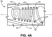
- FIG. 4A is a cross-sectional view of air data probe 300, which has a complete anti-corrosive braze layer.
- FIG. 4B is a cross-sectional view of heating element 302 of air data probe 300 showing braze coverage across heating element 302. FIGS. 4A-B will be discussed together.
- Air data probe 300 includes heating element 302, tube 304, and braze 306.
- Tube 304 includes inner surface 310, which defines cavity 312.
- Heating element 302, tube 304, inner surface 310, and cavity 312, are substantially similar to heating elements 102/202, tubes 104/204, inner surfaces 110/210, and cavities 112/212 respectively, as described with respect to FIGS. 2-3 .
- air data probe 300 can also include one or more sensors for sensing air data.
- Braze 306 covers substantially all of heating element 302, affixing heating element 302 to inner surface 310 and forming a barrier between heating element 302 and cavity 312.
- the continuous barrier formed by braze 306 protects heating element 302 from corrosion-based failure and thereby also functions to prevent corrosion-based failure of heating wire 320, increasing the operational lifespan of heating element 302.
- braze 306 forms a continuous layer that covers all of heating element 302 and at least a portion of inner surface 310 such that there are no uncovered regions of heating element 302.
- braze 306 forms a continuous layer that covers all of heating element 302
- heating element 302 does not have any uncovered regions or weak spots that have increased susceptibility to corrosion.
- heating element 302 has reduced susceptibility to corrosion-based failure and an increased operational lifespan as compared to the uncovered heating element 102 shown in FIG. 2 and the partially covered heating element shown in FIG.3 .
- braze 306 forms a continuous layer that covers the entirety of inner surface 310 and the entirety of inner surface 310, thereby conferring additional environmental protection to inner surface 310 of tube 304.
- FIG. 5 is a flow diagram of method 400, which can be used to create a corrosion-resistant air data probe.
- Method 400 includes steps 402-408 of applying braze material (step 402), positioning the air data probe (step 404), drying the air data probe (step 406), and heating the air data probe (step 408).
- Method 400 optionally includes steps 410-412 of removing excess braze material (step 410) and masking the air data probe (step 412).
- heating element 302 is arranged within tube 304 of air data probe 300.
- a braze material is applied to inner surface 310 and heating element 302 of air data probe 300.
- the braze material is to be applied as a slurry containing a powdered metal and a solvent.
- the metal can be, for example, a mixture of multiple metal materials.
- the braze material applied in step 402 forms braze 306.
- the slurry can also include a viscous element, such as a cement, to increase the viscosity of the slurry.
- tube 304 includes drain holes that are configured to allow for melted ice to flow out of tube 304 as during operation of air data probe 300.
- the drain holes of tube 304 can be plugged prior to application of braze material in step 402 to prevent the braze material slurry from flowing out of the drain holes during method 400.
- air data probe 300 is positioned prior to heating in step 406.
- the position of air data probe 300 is selected to increase coverage and uniformity of braze 306 following heating in step 406, which advantageously improves the anti-corrosion properties conferred by braze 306.
- air data probe 300 can be positioned substantially horizontally such that axis A'-A' is perpendicular to the direction of gravity.
- positioning air data probe 300 substantially horizontally prevents the braze material applied in step 402 from accumulating at an end (i.e., an end along axis A'-A') of tube 304 during drying of the braze material during step 406 prior to heating in step 408.
- step 406 the braze material applied in step 402 is dried to remove solvent from the braze material applied in step 402.
- the duration of drying can be selected based on the volatility of the solvent and the atmospheric conditions in which drying is performed.
- drying the braze material in step 406 reduces the ability of the unbrazed braze material to flow out of tube 304 during subsequent steps of method 400.
- the braze material can flow out of air date probe 300 or flow into regions where it is undesirable for brazing to occur during step 408.
- Air data probe can be cleaned following drying in step 406 to remove dried braze material from areas where brazing should not occur in step 408.
- step 408 air data probe 300 is heated to braze the powdered metal in the braze material applied in step 402, thereby forming a coating of braze 306 on heating element 302 and inner surface 310
- Air data probe 300 can be heated in, for example, a vacuum furnace to braze the metal powder.
- braze 306 formed in step 408 functions both to affix heating element 302 to inner surface 310 and to protect inner surface 310 from corrosion.
- an excess of braze material is applied in step 402.
- the excess of braze material can be applied by, for example, filling cavity 312 with braze material.
- Cavity 313 can be filled with braze material by, for example, placing a cap on an open end of tube 304 and filling cavity 312 by injecting braze material through the cap.
- Air data probe 300 can be oriented substantially vertically such that axis A'-A' is substantially parallel with the direction of gravity as cavity 312 is filled with an excess of braze material.
- applying an excess of braze material increases the uniformity of braze material about inner surface 310 and heating element 302 prior to brazing in step 408.
- method 400 can include step 410 of removing excess braze material after step 402 (applying braze material) and before step 404 (positioning air data probe 300). Excess braze material can be removed by draining or another suitable method.
- method 400 includes step 412 of masking air data probe 300 following step 406 (drying air data probe 300) and before step 408 (heating air data probe 300).
- a masking compound can be applied to one or more areas of air data probe 300 to prevent brazing and/or heat scale formation in those areas during step 408 of method 400.
- the masking compound can be, for example, a mica-based masking compound.
- step 404 Although positioning tube 304 substantially horizontally in step 404 reduces the propensity of braze material to accumulate at an end of tube 304, gravity biases the distribution braze material slurry applied in step 402 to the gravitational bottom of tube 304, reducing the uniformity of coverage of braze 306 following step 408.
- Nonuniform coverage of braze 306 can result in uncovered regions of heating element 302. Similar to uncovered region 224 of heating element 102 of air data probe 200 discussed previously with respect to FIG. 3 , uncovered regions of heating element 302 are susceptible to corrosion.
- method 400 can be repeated multiple times and tube 304 can be placed in a different position or orientation during step 404 of each subsequent iteration.
- changing the position of tube 304 during each subsequent iteration of method 400 can allow for regions that were previously at the gravitational top of tube 304 after step 404 to be placed closer to or at the gravitational bottom of tube 304 during a subsequent iteration.
- the number of iterations can be selected to create a continuous covering of braze 306 over heating element 302 and at least a portion of inner surface 310 such that there are no uncovered regions of heating element 302.
- performing only one iteration of method 400 can create a discontinuous braze layer that does not cover all of heating element 302, similar to braze 206 of air data probe 200.
- subsequent iterations of method 400 can be used to ensure braze 306 coverage of regions that are not covered by braze 306 after a single iteration of method 400.
- the number of iterations of method 400 can be further selected to ensure that the layer of braze 306 does not negatively impact performance of air data probe 300. Excessive braze 306 coverage can reduce the accuracy of measurements made using air data probe 300.
- a limited number of iterations of method 400 can be performed to apply a corrosion-resistant layer of braze 306 to heating element 302 without creating excessive braze 306 coverage that negatively impacts the performance of air data probe 300.
- Air data probe 300 can be positioned in step 404 in each subsequent iteration according to, for example, the desired number of iterations. For example, where two iterations of method 400 are performed, the orientation of air data probe 300 in the second iteration can be rotated 180° about axis A'-A' relative to the orientation of air data probe 300 in the first iteration, such that braze material slurry is biased to different sides of air data probe 300 in different iterations of method 400. As a further example, where three iterations of method 400 of performed, the positions of air data probe 300 in each iteration can be offset by 60° about axis A'-A' relative to each other. Alternatively, air data probe can be rotated 180° about axis A'-A' in each subsequent iteration of method 400.
- air data probe 300 can be further processed by, for example, installation of one or more air data sensors.
- method 400 can be adjusted to improve uniformity of braze following heating in step 408 of method 400.
- the viscosity of the slurry of braze material can affect flow characteristics of the braze material after it is applied to inner surface 310, and can be optimized to reduce accumulation of braze material at the gravitational bottom of tube 304 between steps 404 and 408.
- the rate at which braze material is applied can be selected to reduce settling of powdered metal at the bottom of tube 304 along axis A'-A'.
- the rate at which excess braze material is removed can further be optimized to increase the uniformity of the distribution of unbrazed braze material along inner surface 310 and heating element 302.
- step 408 can be selected to optimize brazing of the braze material.
- rate at which the air data probe is heated can be selected to minimize accumulation of braze material at the gravitational bottom of tube 304 and thereby improve distribution uniformity of braze 306 following step 408.
- method 400 allows for construction of air data probes with improved corrosion resistance as compared to existing methods.
- the improved corrosion resistance imparted by the inner braze layer created using method 400 reduces the susceptibility of an air data probe tube or heating element to corrosion-type failure modes.
- the inner braze layer created using method 400 can further provide protection from other potential environmental effects that can lead to failure of one or more air data probe components.
- An embodiment of a corrosion-resistant air data probe includes a hollow tube having at least one opening, an inner surface of the hollow tube defining an interior cavity, a heating element, and a continuous layer of a braze material.
- the heating element is disposed adjacent to the inner surface, within the interior cavity.
- the continuous layer of the braze material completely covers the heating element and covers at least a portion of the inner surface.
- a corrosion-resistant air data probe includes, among other possible things, a hollow tube having at least one opening, an inner surface of the hollow tube defining an interior cavity, a heating element, and a continuous layer of a braze material.
- the heating element is disposed adjacent to the inner surface, within the interior cavity.
- the continuous layer of the braze material completely covers the heating element and covers at least a portion of the inner surface.
- a further embodiment of the foregoing corrosion-resistant air data probe wherein the inner surface forms a hollow cylinder and the heating element has a helical shape.
- a further embodiment of any of the foregoing corrosion-resistant air data probes wherein the inner surface comprises a first material and the braze material comprises a second material.
- a further embodiment of any of the foregoing corrosion-resistant air data probes wherein the continuous layer of the braze material covers an entirety of the inner surface.
- An embodiment of a method of fabricating an air data probe includes applying a braze material to an inner surface of an air data probe, positioning the air data probe in a first orientation relative to a direction of gravity, heating the air data probe while in the first orientation to braze a braze material to the inner surface and a heating coil disposed adjacent to the inner surface, applying additional braze material to the inner surface after heating the air data probe while in the first orientation, positioning the air data probe in a second orientation relative to the direction of gravity, and heating the air data probe while in the second orientation to braze the additional braze material to the inner surface and the heating coil.
- the air data probe comprises a hollow tube having at least one opening, an interior cavity of the hollow tube is defined by the inner surface, and the hollow tube is oriented along an axis. The second orientation is rotated about the axis relative to the first orientation.
- a method of fabricating an air data probe includes, among other possible things, applying a braze material to an inner surface of an air data probe, positioning the air data probe in a first orientation relative to a direction of gravity, heating the air data probe while in the first orientation to braze a braze material to the inner surface and a heating coil disposed adjacent to the inner surface, applying additional braze material to the inner surface after heating the air data probe while in the first orientation, positioning the air data probe in a second orientation relative to the direction of gravity, and heating the air data probe while in the second orientation to braze the additional braze material to the inner surface and the heating coil.
- the air data probe comprises a hollow tube having at least one opening, an interior cavity of the hollow tube is defined by the inner surface, and the hollow tube is oriented along an axis. The second orientation is rotated about the axis relative
- braze material comprises a slurry
- a further embodiment of any of the foregoing methods of fabricating an air data probe wherein applying the braze material to the inner surface of the air data probe comprises applying an excess of the braze material to the inner surface and removing a portion of the braze material from the inner surface after applying the excess of the braze material.
- a further embodiment of any of the foregoing methods of fabricating an air data probe further comprising at least partially drying the braze material after positioning the air data probe in the first orientation and before heating the air data probe in the first orientation.
- a further embodiment of any of the foregoing methods of fabricating an air data probe further comprising at least partially drying the braze material after position the air data probe in the second orientation and before heating the air data probe in the second orientation.
- a further embodiment of any of the foregoing methods of fabricating an air data probe further comprising applying additional braze material to the interior cavity of the air data probe after heating the air data probe while in the second orientation, positioning the air data probe in a third orientation, and heating the air data probe while in the third orientation to braze the additional braze material to the inner surface and the heating coil.
- a further embodiment of any of the foregoing methods of fabricating an air data probe wherein a continuous layer of the braze material covering the heating element and covering at least a portion of the inner surface is formed after heating the air data probe while in the second orientation.
- a further embodiment of any of the foregoing methods of fabricating an air data probe further comprising attaching a nose cap to one opening of the tube before applying the braze material to the inner surface, wherein applying the braze material comprises injecting the braze material into the interior cavity through the nose cap.
- a further embodiment of any of the foregoing methods of fabricating an air data probe further comprising applying a masking compound to a portion of the tube after applying a braze material and before heating the air data probe while in the first orientation.
Landscapes
- Engineering & Computer Science (AREA)
- Aviation & Aerospace Engineering (AREA)
- Physics & Mathematics (AREA)
- General Physics & Mathematics (AREA)
- Mechanical Engineering (AREA)
- Testing Resistance To Weather, Investigating Materials By Mechanical Methods (AREA)
Abstract
Description
- This application claims the benefit of
U. S. Provisional Application No. 63/282,911 filed November 24, 2021 for "ANTI-CORROSIVE BRAZE COATINGS" by D. Teigen, K. Rose, C. Kuha, and K. Wachter - The present disclosure relates to air data probes, and more particularly, to air data probes with improved corrosion resistance.
- Air data probe devices can be utilized in, e.g., aerospace applications for measuring environmental parameters usable to determine air data outputs. For instance, air data probes can measure pitot pressure, static pressure, or other parameters of airflow across the air data probe that are usable for determining air data outputs, such as pressure altitude, altitude rate (e.g., vertical speed), airspeed, Mach number, angle of attack, angle of sideslip, or other air data outputs. Such air data probes often include one or more air data sensing ports, such as static pressure ports located on the side of the probe integral to the surface of the probe that are pneumatically connected to sensors that sense the atmospheric pressure outside of the aircraft. Certain flight conditions can cause ice accumulation within an air data probe, degrading air data probe performance.
- In one embodiment, a corrosion-resistant air data probe includes a hollow tube having at least one opening, an inner surface of the hollow tube defining an interior cavity, a heating element, and a continuous layer of a braze material. The heating element is disposed adjacent to the inner surface, within the interior cavity. The continuous layer of the braze material completely covers the heating element and covers at least a portion of the inner surface.
- In another embodiment, a method of fabricating an air data probe includes applying a braze material to an inner surface of an air data probe, positioning the air data probe in a first orientation relative to a direction of gravity, heating the air data probe while in the first orientation to braze a braze material to the inner surface and a heating coil disposed adjacent to the inner surface, applying additional braze material to the inner surface after heating the air data probe while in the first orientation, positioning the air data probe in a second orientation relative to the direction of gravity, and heating the air data probe while in the second orientation to braze the additional braze material to the inner surface and the heating coil. The air data probe comprises a hollow tube having at least one opening, an interior cavity of the hollow tube is defined by the inner surface, and the hollow tube is oriented along an axis. The second orientation is rotated about the axis relative to the first orientation.
- The present summary is provided only by way of example, and not limitation. Other aspects of the present disclosure will be appreciated in view of the entirety of the present disclosure, including the entire text, claims, and accompanying figures.
-
-
FIG. 1 is a perspective view of an example of an air data probe. -
FIG. 2 is a cross-sectional image of an example of an air data probe. -
FIG. 3 is a cross-sectional image of an example of an air data probe having a partial anti-corrosive braze layer. -
FIG. 4A is a cross-sectional image of an example of an air data probe having an anti-corrosive braze layer. -
FIG. 4B is a cross-sectional image the heating element of the air data probe ofFIG. 4A . -
FIG. 5 is a flow diagram of an example of a method of fabricating a corrosion-resistant air data probe. - While the above-identified figures set forth one or more embodiments of the present disclosure, other embodiments are also contemplated, as noted in the discussion. In all cases, this disclosure presents the invention by way of representation and not limitation. It should be understood that numerous other modifications and embodiments can be devised by those skilled in the art, which fall within the scope and spirit of the principles of the invention. The figures may not be drawn to scale, and applications and embodiments of the present invention may include features and components not specifically shown in the drawings.
- The present disclosure includes systems and methods of for improving corrosion resistance of air data probes. More specifically, the systems and methods disclosed herein use a layer of brazed material to protect heating elements and/or air data probe surfaces from corrosion. The systems and methods disclosed herein advantageously reduce the susceptibility of air data probes to corrosion-based failure.
-
FIG. 1 is a perspective view ofair data probe 10.Air data probe 10 includestube 14 andsensing ports 26 and 28. In the depicted example,tube 14 includes a barrel- or cylinder-shaped portion and a tapered or conically-shaped section leading to sensing port 28. However,tube 14 can have other suitable geometries.Sensing ports 26 and 28 are formed integrally withtube 14 and are pneumatically connected to one or more sensors.Sensing ports 26 and 28 allowair data probe 10 to sense air data whenair data probe 10 is placed in a flow or air. As depicted,sensing port 26 is a pitot pressure sensing port and sensing port 28 is a static pressure sensing port. However,air data probe 10 can have other combinations of one or more sensing ports for sensing a variety of air data. -
FIG. 2 is a cross-sectional image of prior artair data probe 100.Air data probe 100 has overall structure as disclosed generally with regard toair data probe 10 ofFIG. 1 .Air data probe 100 includesheating element 102,tube 104, andbraze 106. Tube 104 includesinner surface 110, which definescavity 112. In the depicted example,tube 104 has a hollow conical shape and extends generally along axis A-A. However,tube 104 can be formed into other suitable shapes or combinations of multiple shapes. For example,tube 104 can be formed as a hollow cylinder. In another example,tube 104 can include both cylindrical and conical sections.Inner surface 110 definescavity 112 and forms a channel through which a fluid, such as air, can flow or accumulate. Similar totube 14,tube 104 has one or more openings or ports (not shown) such thatair data probe 100 can take in air from a flow of air. One or more sensors can be coupled to and/or integrated withtube 104 for measuring air data. In operation,air data probe 100 is placed in a flow of air to measure air data of the flow of air. In some examples,air data probe 100 can be attached to an aircraft and used to determine one or more of pressure altitude, altitude rate (e.g., vertical speed), airspeed, Mach number, angle of attack, angle of sideslip, air speed, or another suitable air data parameter. -
Heating element 102 is disposed withintube 104 adjacent toinner surface 110 and extends away frominner surface 110 intocavity 112.Heating element 102 is a resistive heating element configured to heatinner surface 110 during operation ofair data probe 100.Heating element 102 is affixed toinner surface 110 by brazing, forming fillets ofbraze 106 betweenheating element 102 andinner surface 110. The portion ofheating element 102 extending away frominner surface 110 is exposed to air incavity 112. InFIG. 2 ,heating element 102 has a helical shape and wrap helically aroundinner surface 110 oftube 104. The helical shape ofheating element 102 depicted inFIGS. 2 improves uniformity of heating ofinner surface 110. However, in other examples,heating element 102 has other shapes. In some examples,tube 104 is formed of a nickel material. In further examples,braze 106 is comprises a mixture of metals. - In low temperature conditions, ice can form on
inner surface 110 and clogtube 104, impeding the flow of air throughcavity 112 and thereby reducing the accuracy of air data collected withair data probe 100.Heating element 102 reduces ice formation alonginner surface 110 by applying heat toinner surface 110. However, in corrosive environments, repeated heating and cooling ofheating element 102 can cause corrosion ofheating element 102 and/ortube 104, potentially leading to failure ofheating element 102,tube 104, or another component ofair data probe 100. The corrosive environment can be, for example, a saltwater air environment. -
FIG. 3 is a cross-sectional diagram ofair data probe 200, which has a partial layer of anti-corrosive braze material as compared to prior artair data probe 100, which lacks any layer of anti-corrosive braze material.Air data probe 200 includesheating element 202,tube 204,braze 206,inner surface 210,cavity 212, and uncoveredregion 224.Air data probe 200 is substantially similar toair data probe 100 and can perform substantially the same functions asair data probe 100, but includesbraze 206, which covers more ofheating element 102.Heating element 202,tube 204,inner surface 210, andcavity 212 are substantially similar toheating element 102,tube 104,inner surface 110, andcavity 112, respectively, as described with respect toFIGS. 2 . - Like
braze 106, braze 206 affixesheating element 202 toinner surface 210 and can be formed of a metal material or a mixture of metal materials. However, braze 206 is formed of more braze material thanbraze 206 and covers more ofheating element 202 thanbraze 106 covers ofheating element 102. Notably, althoughbraze 206 includes more braze material thanbraze 106, braze 206 does not cover allheating element 202. Specifically,uncovered region 224 ofheating element 202 is not covered bybraze 206. -
Braze 206 confers corrosion protection toheating element 202 wherebraze 206 coversheating element 202. Atuncovered region 224,heating element 202 has degraded due to corrosion, reducing or eliminating the ability ofheating element 202 to melt ice that has accumulated oninner surface 210 oftube 204. To this extent,uncovered region 224 is a weak spot ofheating element 202 that is not protected by a layer ofbraze 206 and that has increased susceptibility to corrosion as compared to the portions ofheating element 102 that are covered by a layer ofbraze 206. -
FIG. 4A is a cross-sectional view ofair data probe 300, which has a complete anti-corrosive braze layer.FIG. 4B is a cross-sectional view ofheating element 302 ofair data probe 300 showing braze coverage acrossheating element 302.FIGS. 4A-B will be discussed together. -
Air data probe 300 includesheating element 302,tube 304, and braze 306.Tube 304 includesinner surface 310, which definescavity 312.Heating element 302,tube 304,inner surface 310, andcavity 312, are substantially similar toheating elements 102/202,tubes 104/204,inner surfaces 110/210, andcavities 112/212 respectively, as described with respect toFIGS. 2-3 . Like air data probes 100 and 200,air data probe 300 can also include one or more sensors for sensing air data. -
Braze 306 covers substantially all ofheating element 302, affixingheating element 302 toinner surface 310 and forming a barrier betweenheating element 302 andcavity 312. Advantageously, the continuous barrier formed bybraze 306 protectsheating element 302 from corrosion-based failure and thereby also functions to prevent corrosion-based failure of heating wire 320, increasing the operational lifespan ofheating element 302. - As shown more clearly in
FIG. 4B , braze 306 forms a continuous layer that covers all ofheating element 302 and at least a portion ofinner surface 310 such that there are no uncovered regions ofheating element 302. Asbraze 306 forms a continuous layer that covers all ofheating element 302,heating element 302 does not have any uncovered regions or weak spots that have increased susceptibility to corrosion. To this extent,heating element 302 has reduced susceptibility to corrosion-based failure and an increased operational lifespan as compared to the uncoveredheating element 102 shown inFIG. 2 and the partially covered heating element shown inFIG.3 . In some examples, braze 306 forms a continuous layer that covers the entirety ofinner surface 310 and the entirety ofinner surface 310, thereby conferring additional environmental protection toinner surface 310 oftube 304. -
FIG. 5 is a flow diagram ofmethod 400, which can be used to create a corrosion-resistant air data probe.Method 400 includes steps 402-408 of applying braze material (step 402), positioning the air data probe (step 404), drying the air data probe (step 406), and heating the air data probe (step 408).Method 400 optionally includes steps 410-412 of removing excess braze material (step 410) and masking the air data probe (step 412). - Prior to or as a preliminary step of
method 400,heating element 302 is arranged withintube 304 ofair data probe 300. Instep 402 ofmethod 400, a braze material is applied toinner surface 310 andheating element 302 ofair data probe 300. To improve distribution of braze material alonginner surface 310 andheating element 302, the braze material is to be applied as a slurry containing a powdered metal and a solvent. The metal can be, for example, a mixture of multiple metal materials. Following heating instep 406, the braze material applied instep 402 forms braze 306. In some examples, the slurry can also include a viscous element, such as a cement, to increase the viscosity of the slurry. Advantageously, the viscosity of the slurry can be selected to improve coverage of the braze material following heating instep 408, as will be explained in more detail subsequently. In some examples,tube 304 includes drain holes that are configured to allow for melted ice to flow out oftube 304 as during operation ofair data probe 300. In these examples, the drain holes oftube 304 can be plugged prior to application of braze material instep 402 to prevent the braze material slurry from flowing out of the drain holes duringmethod 400. - In
step 404,air data probe 300 is positioned prior to heating instep 406. The position ofair data probe 300 is selected to increase coverage and uniformity ofbraze 306 following heating instep 406, which advantageously improves the anti-corrosion properties conferred bybraze 306. For example,air data probe 300 can be positioned substantially horizontally such that axis A'-A' is perpendicular to the direction of gravity. Advantageously, positioningair data probe 300 substantially horizontally prevents the braze material applied instep 402 from accumulating at an end (i.e., an end along axis A'-A') oftube 304 during drying of the braze material duringstep 406 prior to heating instep 408. - In
step 406, the braze material applied instep 402 is dried to remove solvent from the braze material applied instep 402. The duration of drying can be selected based on the volatility of the solvent and the atmospheric conditions in which drying is performed. Advantageously, drying the braze material instep 406 reduces the ability of the unbrazed braze material to flow out oftube 304 during subsequent steps ofmethod 400. As the braze material is in a slurry form until heating duringstep 408, the braze material can flow out ofair date probe 300 or flow into regions where it is undesirable for brazing to occur duringstep 408. Air data probe can be cleaned following drying instep 406 to remove dried braze material from areas where brazing should not occur instep 408. - In
step 408,air data probe 300 is heated to braze the powdered metal in the braze material applied instep 402, thereby forming a coating ofbraze 306 onheating element 302 andinner surface 310Air data probe 300 can be heated in, for example, a vacuum furnace to braze the metal powder. Advantageously, braze 306 formed instep 408 functions both to affixheating element 302 toinner surface 310 and to protectinner surface 310 from corrosion. - In some examples of
method 400, an excess of braze material is applied instep 402. The excess of braze material can be applied by, for example, fillingcavity 312 with braze material. Cavity 313 can be filled with braze material by, for example, placing a cap on an open end oftube 304 and fillingcavity 312 by injecting braze material through the cap.Air data probe 300 can be oriented substantially vertically such that axis A'-A' is substantially parallel with the direction of gravity ascavity 312 is filled with an excess of braze material. Advantageously, applying an excess of braze material increases the uniformity of braze material aboutinner surface 310 andheating element 302 prior to brazing instep 408. In examples where an excess of braze material,method 400 can include step 410 of removing excess braze material after step 402 (applying braze material) and before step 404 (positioning air data probe 300). Excess braze material can be removed by draining or another suitable method. - In further examples,
method 400 includesstep 412 of maskingair data probe 300 following step 406 (drying air data probe 300) and before step 408 (heating air data probe 300). Instep 412, a masking compound can be applied to one or more areas ofair data probe 300 to prevent brazing and/or heat scale formation in those areas duringstep 408 ofmethod 400. The masking compound can be, for example, a mica-based masking compound. - Although positioning
tube 304 substantially horizontally instep 404 reduces the propensity of braze material to accumulate at an end oftube 304, gravity biases the distribution braze material slurry applied instep 402 to the gravitational bottom oftube 304, reducing the uniformity of coverage ofbraze 306 followingstep 408. Nonuniform coverage ofbraze 306 can result in uncovered regions ofheating element 302. Similar touncovered region 224 ofheating element 102 ofair data probe 200 discussed previously with respect toFIG. 3 , uncovered regions ofheating element 302 are susceptible to corrosion. To reduce or eliminate uncovered regions ofheating element 302,method 400 can be repeated multiple times andtube 304 can be placed in a different position or orientation duringstep 404 of each subsequent iteration. Advantageously, changing the position oftube 304 during each subsequent iteration ofmethod 400 can allow for regions that were previously at the gravitational top oftube 304 afterstep 404 to be placed closer to or at the gravitational bottom oftube 304 during a subsequent iteration. - The number of iterations can be selected to create a continuous covering of
braze 306 overheating element 302 and at least a portion ofinner surface 310 such that there are no uncovered regions ofheating element 302. In some examples, performing only one iteration ofmethod 400 can create a discontinuous braze layer that does not cover all ofheating element 302, similar to braze 206 ofair data probe 200. In these examples, subsequent iterations ofmethod 400 can be used to ensurebraze 306 coverage of regions that are not covered bybraze 306 after a single iteration ofmethod 400. - The number of iterations of
method 400 can be further selected to ensure that the layer ofbraze 306 does not negatively impact performance ofair data probe 300.Excessive braze 306 coverage can reduce the accuracy of measurements made usingair data probe 300. Advantageously, a limited number of iterations ofmethod 400 can be performed to apply a corrosion-resistant layer ofbraze 306 toheating element 302 without creatingexcessive braze 306 coverage that negatively impacts the performance ofair data probe 300. -
Air data probe 300 can be positioned instep 404 in each subsequent iteration according to, for example, the desired number of iterations. For example, where two iterations ofmethod 400 are performed, the orientation ofair data probe 300 in the second iteration can be rotated 180° about axis A'-A' relative to the orientation ofair data probe 300 in the first iteration, such that braze material slurry is biased to different sides ofair data probe 300 in different iterations ofmethod 400. As a further example, where three iterations ofmethod 400 of performed, the positions ofair data probe 300 in each iteration can be offset by 60° about axis A'-A' relative to each other. Alternatively, air data probe can be rotated 180° about axis A'-A' in each subsequent iteration ofmethod 400. - After the desired number of iterations of
method 400 have been performed and an anti-corrosion layer of braze has been formed oninner surface 310 andheating element 302 ofair data probe 300,air data probe 300 can be further processed by, for example, installation of one or more air data sensors. - Other operational parameters of
method 400 can be adjusted to improve uniformity of braze following heating instep 408 ofmethod 400. The viscosity of the slurry of braze material can affect flow characteristics of the braze material after it is applied toinner surface 310, and can be optimized to reduce accumulation of braze material at the gravitational bottom oftube 304 betweensteps step 402, the rate at which braze material is applied can be selected to reduce settling of powdered metal at the bottom oftube 304 along axis A'-A'. Wheremethod 400 includesstep 410, the rate at which excess braze material is removed can further be optimized to increase the uniformity of the distribution of unbrazed braze material alonginner surface 310 andheating element 302. Generally, increasing the rate at which excess braze material is removed can increase the uniformity of the unbrazed braze material. Further, temperature to which the air data probe is heated instep 408 can be selected to optimize brazing of the braze material. Similarly, the rate at which the air data probe is heated can be selected to minimize accumulation of braze material at the gravitational bottom oftube 304 and thereby improve distribution uniformity ofbraze 306 followingstep 408. - Advantageously,
method 400 allows for construction of air data probes with improved corrosion resistance as compared to existing methods. The improved corrosion resistance imparted by the inner braze layer created usingmethod 400 reduces the susceptibility of an air data probe tube or heating element to corrosion-type failure modes. In addition to conferring corrosion-protection, the inner braze layer created usingmethod 400 can further provide protection from other potential environmental effects that can lead to failure of one or more air data probe components. - The following are non-exclusive descriptions of possible embodiments of the present invention.
- An embodiment of a corrosion-resistant air data probe includes a hollow tube having at least one opening, an inner surface of the hollow tube defining an interior cavity, a heating element, and a continuous layer of a braze material. The heating element is disposed adjacent to the inner surface, within the interior cavity. The continuous layer of the braze material completely covers the heating element and covers at least a portion of the inner surface.
- The corrosion-resistant air data probe of the preceding paragraph can optionally include, additionally and/or alternatively, any one or more of the following features, configurations and/or additional components:
A corrosion-resistant air data probe according to an exemplary embodiment of this disclosure includes, among other possible things, a hollow tube having at least one opening, an inner surface of the hollow tube defining an interior cavity, a heating element, and a continuous layer of a braze material. The heating element is disposed adjacent to the inner surface, within the interior cavity. The continuous layer of the braze material completely covers the heating element and covers at least a portion of the inner surface. - A further embodiment of the foregoing corrosion-resistant air data probe, wherein the inner surface forms a hollow cylinder and the heating element has a helical shape.
- A further embodiment of any of the foregoing corrosion-resistant air data probes, wherein the inner surface comprises a first material and the braze material comprises a second material.
- A further embodiment of any of the foregoing corrosion-resistant air data probes, wherein the continuous layer of the braze material covers an entirety of the inner surface.
- An embodiment of a method of fabricating an air data probe includes applying a braze material to an inner surface of an air data probe, positioning the air data probe in a first orientation relative to a direction of gravity, heating the air data probe while in the first orientation to braze a braze material to the inner surface and a heating coil disposed adjacent to the inner surface, applying additional braze material to the inner surface after heating the air data probe while in the first orientation, positioning the air data probe in a second orientation relative to the direction of gravity, and heating the air data probe while in the second orientation to braze the additional braze material to the inner surface and the heating coil. The air data probe comprises a hollow tube having at least one opening, an interior cavity of the hollow tube is defined by the inner surface, and the hollow tube is oriented along an axis. The second orientation is rotated about the axis relative to the first orientation.
- The method of fabricating an air data probe preceding paragraph can optionally include, additionally and/or alternatively, any one or more of the following features, configurations and/or additional components:
A method of fabricating an air data probe according to an exemplary embodiment of this disclosure includes, among other possible things, applying a braze material to an inner surface of an air data probe, positioning the air data probe in a first orientation relative to a direction of gravity, heating the air data probe while in the first orientation to braze a braze material to the inner surface and a heating coil disposed adjacent to the inner surface, applying additional braze material to the inner surface after heating the air data probe while in the first orientation, positioning the air data probe in a second orientation relative to the direction of gravity, and heating the air data probe while in the second orientation to braze the additional braze material to the inner surface and the heating coil. The air data probe comprises a hollow tube having at least one opening, an interior cavity of the hollow tube is defined by the inner surface, and the hollow tube is oriented along an axis. The second orientation is rotated about the axis relative to the first orientation. - A further embodiment of the foregoing method of fabricating an air data probe, wherein the second orientation is rotated 180 degrees about the axis relative to the first orientation.
- A further embodiment of any of the foregoing methods of fabricating an air data probe, wherein the axis is orthogonal to the direction of gravity when the air data probe is positioned in the first orientation and in the second orientation.
- A further embodiment of any of the foregoing methods of fabricating an air data probe, wherein the axis is substantially parallel to the direction of gravity while the braze material is applied.
- A further embodiment of any of the foregoing methods of fabricating an air data probe, wherein the braze material comprises a slurry.
- A further embodiment of any of the foregoing methods of fabricating an air data probe, wherein the slurry further comprises a cement material.
- A further embodiment of any of the foregoing methods of fabricating an air data probe, wherein applying the braze material to the inner surface of the air data probe comprises applying an excess of the braze material to the inner surface and removing a portion of the braze material from the inner surface after applying the excess of the braze material.
- A further embodiment of any of the foregoing methods of fabricating an air data probe, further comprising at least partially drying the braze material after positioning the air data probe in the first orientation and before heating the air data probe in the first orientation.
- A further embodiment of any of the foregoing methods of fabricating an air data probe, further comprising at least partially drying the braze material after position the air data probe in the second orientation and before heating the air data probe in the second orientation.
- A further embodiment of any of the foregoing methods of fabricating an air data probe, wherein the inner surface is formed of a material that is different than the braze material.
- A further embodiment of any of the foregoing methods of fabricating an air data probe, further comprising applying additional braze material to the interior cavity of the air data probe after heating the air data probe while in the second orientation, positioning the air data probe in a third orientation, and heating the air data probe while in the third orientation to braze the additional braze material to the inner surface and the heating coil.
- A further embodiment of any of the foregoing methods of fabricating an air data probe, wherein the third orientation is rotated about the axis relative to the second orientation.
- A further embodiment of any of the foregoing methods of fabricating an air data probe, wherein a continuous layer of the braze material covering the heating element and covering at least a portion of the inner surface is formed after heating the air data probe while in the second orientation.
- A further embodiment of any of the foregoing methods of fabricating an air data probe, wherein the continuous layer of the braze material covers an entirety of the inner surface.
- A further embodiment of any of the foregoing methods of fabricating an air data probe, wherein the inner surface forms a hollow cylinder and the heating element has a helical shape.
- A further embodiment of any of the foregoing methods of fabricating an air data probe, further comprising attaching a nose cap to one opening of the tube before applying the braze material to the inner surface, wherein applying the braze material comprises injecting the braze material into the interior cavity through the nose cap.
- A further embodiment of any of the foregoing methods of fabricating an air data probe, further comprising applying a masking compound to a portion of the tube after applying a braze material and before heating the air data probe while in the first orientation.
- While the invention has been described with reference to an exemplary embodiment(s), it will be understood by those skilled in the art that various changes may be made and equivalents may be substituted for elements thereof without departing from the scope of the invention. In addition, many modifications may be made to adapt a particular situation or material to the teachings of the invention without departing from the essential scope thereof. Therefore, it is intended that the invention not be limited to the particular embodiment(s) disclosed, but that the invention will include all embodiments falling within the scope of the appended claims.
Claims (15)
- A corrosion-resistant air data probe comprising:a hollow tube (204, 304) having at least one opening;an inner surface of the hollow tube (204, 304) defining an interior cavity (112);a heating element disposed adjacent to the inner surface, within the interior cavity (112); anda continuous layer of a braze material completely covering the heating element and covering at least a portion of the inner surface.
- The corrosion-resistant air data probe of claim 1, wherein the inner surface forms a hollow cylinder and the heating element has a helical shape, or wherein the inner surface comprises a first material and the braze material comprises a second material.
- The corrosion-resistant air data probe of any preceding claim, wherein the continuous layer of the braze material covers an entirety of the inner surface.
- A method of fabricating an air data probe, the method comprising:applying a braze material to an inner surface of an air data probe, wherein:the air data probe comprises a hollow tube (204, 304) having at least one opening;an interior cavity (112) of the hollow tube (204, 304) is defined by the inner surface;a heating coil is disposed adjacent to the inner surface; andthe hollow tube (204, 304) is oriented along an axis;positioning the air data probe in a first orientation relative to a direction of gravity;heating the air data probe while in the first orientation to braze the braze material to the inner surface and the heating coil;applying additional braze material to the inner surface of the air data probe after heating the air data probe while in the first orientation;positioning the air data probe in a second orientation relative to the direction of gravity, wherein the second orientation is rotated about the axis relative to the first orientation;heating the air data probe while in the second orientation to braze the additional braze material to the inner surface and the heating coil.
- The method of claim 4, wherein the second orientation is rotated 180 degrees about the axis relative to the first orientation.
- The method of claim 4 or 5, wherein the axis is orthogonal to the direction of gravity when the air data probe is positioned in the first orientation and in the second orientation, or wherein the axis is substantially parallel to the direction of gravity while the braze material is applied.
- The method of any of claims 4 to 6, wherein the braze material comprises a slurry, and optionally wherein the slurry further comprises a cement material.
- The method of any of claims 4 to 7, wherein applying the braze material to the inner surface of the air data probe comprises:applying an excess of the braze material to the inner surface; andremoving a portion of the braze material from the inner surface after applying the excess of the braze material.
- The method of any of claims 4 to 8, further comprising at least partially drying the braze material after positioning the air data probe in the first orientation and before heating the air data probe in the first orientation, or further comprising at least partially drying the braze material after positioning the air data probe in the second orientation and before heating the air data probe in the second orientation.
- The method of any of claims 4 to 9, wherein the inner surface is formed of a material that is different than the braze material.
- The method of any of claims 4 to 10, further comprising:applying additional braze material to the interior cavity (112) of the air data probe after heating the air data probe while in the second orientation;positioning the air data probe in a third orientation, wherein the third orientation is rotated about the axis relative to the second orientation;heating the air data probe while in the third orientation to braze the additional braze material to the inner surface and the heating coil.
- The method of any of claims 4 to 11, wherein a continuous layer of the braze material covering the heating element and covering at least a portion of the inner surface is formed after heating the air data probe while in the second orientation, and optionally wherein the continuous layer of the braze material covers an entirety of the inner surface.
- The method of any of claims 4 to 12, wherein the inner surface forms a hollow cylinder and the heating element has a helical shape.
- The method of any of claims 4 to 13, further comprising attaching a nose cap to one opening of the tube (204, 304) before applying the braze material to the inner surface, wherein applying the braze material comprises injecting the braze material into the interior cavity (112) through the nose cap.
- The method of any of claims 4 to 14, further comprising applying a masking compound to a portion of the tube (204, 304) after applying a braze material and before heating the air data probe while in the first orientation.
Applications Claiming Priority (2)
| Application Number | Priority Date | Filing Date | Title |
|---|---|---|---|
| US202163282911P | 2021-11-24 | 2021-11-24 | |
| US17/561,419 US11845136B2 (en) | 2021-11-24 | 2021-12-23 | Anti-corrosive braze coatings |
Publications (1)
| Publication Number | Publication Date |
|---|---|
| EP4187256A1 true EP4187256A1 (en) | 2023-05-31 |
Family
ID=84361751
Family Applications (1)
| Application Number | Title | Priority Date | Filing Date |
|---|---|---|---|
| EP22209319.7A Pending EP4187256A1 (en) | 2021-11-24 | 2022-11-24 | Anti-corrosive braze coatings for air data probes |
Country Status (4)
| Country | Link |
|---|---|
| US (1) | US11845136B2 (en) |
| EP (1) | EP4187256A1 (en) |
| BR (1) | BR102022023859A2 (en) |
| CA (1) | CA3174612A1 (en) |
Citations (4)
| Publication number | Priority date | Publication date | Assignee | Title |
|---|---|---|---|---|
| US20190186974A1 (en) * | 2015-03-23 | 2019-06-20 | Rosemount Aerospace Inc. | Corrosion resistant sleeve for an air data probe |
| US20190291879A1 (en) * | 2018-03-23 | 2019-09-26 | Rosemount Aerospace Inc. | Surface modified heater assembly |
| EP3715859A1 (en) * | 2019-03-25 | 2020-09-30 | Rosemount Aerospace Inc. | Air data probe with fully-encapsulated heater |
| US20200333206A1 (en) * | 2015-03-23 | 2020-10-22 | Rosemount Aerospace Inc. | Corrosion resistant sleeve for an air data probe |
Family Cites Families (5)
| Publication number | Priority date | Publication date | Assignee | Title |
|---|---|---|---|---|
| US10227139B2 (en) * | 2015-03-23 | 2019-03-12 | Rosemount Aerospace Inc. | Heated air data probes |
| US10384787B2 (en) | 2016-06-23 | 2019-08-20 | Honeywell International Inc. | Forming an air data probe from a porous cover and brazing material |
| US11262227B2 (en) * | 2018-10-05 | 2022-03-01 | Rosemount Aerospace Inc. | Pitot tube heater assembly |
| US11629403B2 (en) * | 2018-10-19 | 2023-04-18 | Rosemount Aerospace Inc. | Air data probe corrosion protection |
| CA3067550A1 (en) * | 2019-01-17 | 2020-07-17 | Goodrich Corporation | Pitot tube |
-
2021
- 2021-12-23 US US17/561,419 patent/US11845136B2/en active Active
-
2022
- 2022-09-14 CA CA3174612A patent/CA3174612A1/en active Pending
- 2022-11-23 BR BR102022023859-6A patent/BR102022023859A2/en unknown
- 2022-11-24 EP EP22209319.7A patent/EP4187256A1/en active Pending
Patent Citations (4)
| Publication number | Priority date | Publication date | Assignee | Title |
|---|---|---|---|---|
| US20190186974A1 (en) * | 2015-03-23 | 2019-06-20 | Rosemount Aerospace Inc. | Corrosion resistant sleeve for an air data probe |
| US20200333206A1 (en) * | 2015-03-23 | 2020-10-22 | Rosemount Aerospace Inc. | Corrosion resistant sleeve for an air data probe |
| US20190291879A1 (en) * | 2018-03-23 | 2019-09-26 | Rosemount Aerospace Inc. | Surface modified heater assembly |
| EP3715859A1 (en) * | 2019-03-25 | 2020-09-30 | Rosemount Aerospace Inc. | Air data probe with fully-encapsulated heater |
Also Published As
| Publication number | Publication date |
|---|---|
| US20230158594A1 (en) | 2023-05-25 |
| BR102022023859A2 (en) | 2023-11-07 |
| US11845136B2 (en) | 2023-12-19 |
| CA3174612A1 (en) | 2023-05-24 |
Similar Documents
| Publication | Publication Date | Title |
|---|---|---|
| EP3633387B1 (en) | Pitot tube heater assembly | |
| US11731782B2 (en) | Bulkheads for air data probes | |
| EP3499217B1 (en) | Air data probe with a heater coil protection arrangement | |
| EP3076185B1 (en) | Corrosion-resistant heated air data probe | |
| JP4404104B2 (en) | Air flow measurement device | |
| EP3715859B1 (en) | Air data probe with fully-encapsulated heater | |
| CN106466713A (en) | System and method for the increasing material manufacturing of air data probe | |
| EP3106881B1 (en) | Pitot tube moisture removal enhancement | |
| CA3067550A1 (en) | Pitot tube | |
| US11845136B2 (en) | Anti-corrosive braze coatings | |
| US11866179B2 (en) | Surface modified heater assembly | |
| US11209330B2 (en) | Corrosion resistant sleeve for an air data probe | |
| CN111602043B (en) | Protective device | |
| EP0580608B1 (en) | Device for measuring a gas flow, and method for using the device |
Legal Events
| Date | Code | Title | Description |
|---|---|---|---|
| PUAI | Public reference made under article 153(3) epc to a published international application that has entered the european phase |
Free format text: ORIGINAL CODE: 0009012 |
|
| STAA | Information on the status of an ep patent application or granted ep patent |
Free format text: STATUS: THE APPLICATION HAS BEEN PUBLISHED |
|
| AK | Designated contracting states |
Kind code of ref document: A1 Designated state(s): AL AT BE BG CH CY CZ DE DK EE ES FI FR GB GR HR HU IE IS IT LI LT LU LV MC ME MK MT NL NO PL PT RO RS SE SI SK SM TR |
|
| STAA | Information on the status of an ep patent application or granted ep patent |
Free format text: STATUS: REQUEST FOR EXAMINATION WAS MADE |
|
| 17P | Request for examination filed |
Effective date: 20231130 |
|
| RBV | Designated contracting states (corrected) |
Designated state(s): AL AT BE BG CH CY CZ DE DK EE ES FI FR GB GR HR HU IE IS IT LI LT LU LV MC ME MK MT NL NO PL PT RO RS SE SI SK SM TR |
|
| STAA | Information on the status of an ep patent application or granted ep patent |
Free format text: STATUS: EXAMINATION IS IN PROGRESS |
|
| 17Q | First examination report despatched |
Effective date: 20250213 |