EP4187212A1 - Contactless waste tank level sensing systems and methods - Google Patents
Contactless waste tank level sensing systems and methods Download PDFInfo
- Publication number
- EP4187212A1 EP4187212A1 EP22209090.4A EP22209090A EP4187212A1 EP 4187212 A1 EP4187212 A1 EP 4187212A1 EP 22209090 A EP22209090 A EP 22209090A EP 4187212 A1 EP4187212 A1 EP 4187212A1
- Authority
- EP
- European Patent Office
- Prior art keywords
- waste tank
- controller
- contactless sensor
- water level
- waste
- Prior art date
- Legal status (The legal status is an assumption and is not a legal conclusion. Google has not performed a legal analysis and makes no representation as to the accuracy of the status listed.)
- Granted
Links
Images


Classifications
-
- B—PERFORMING OPERATIONS; TRANSPORTING
- B64—AIRCRAFT; AVIATION; COSMONAUTICS
- B64D—EQUIPMENT FOR FITTING IN OR TO AIRCRAFT; FLIGHT SUITS; PARACHUTES; ARRANGEMENT OR MOUNTING OF POWER PLANTS OR PROPULSION TRANSMISSIONS IN AIRCRAFT
- B64D11/00—Passenger or crew accommodation; Flight-deck installations not otherwise provided for
- B64D11/02—Toilet fittings
-
- G—PHYSICS
- G01—MEASURING; TESTING
- G01F—MEASURING VOLUME, VOLUME FLOW, MASS FLOW OR LIQUID LEVEL; METERING BY VOLUME
- G01F23/00—Indicating or measuring liquid level or level of fluent solid material, e.g. indicating in terms of volume or indicating by means of an alarm
- G01F23/22—Indicating or measuring liquid level or level of fluent solid material, e.g. indicating in terms of volume or indicating by means of an alarm by measuring physical variables, other than linear dimensions, pressure or weight, dependent on the level to be measured, e.g. by difference of heat transfer of steam or water
- G01F23/28—Indicating or measuring liquid level or level of fluent solid material, e.g. indicating in terms of volume or indicating by means of an alarm by measuring physical variables, other than linear dimensions, pressure or weight, dependent on the level to be measured, e.g. by difference of heat transfer of steam or water by measuring the variations of parameters of electromagnetic or acoustic waves applied directly to the liquid or fluent solid material
- G01F23/284—Electromagnetic waves
- G01F23/292—Light, e.g. infrared or ultraviolet
Definitions
- the present disclosure relates to drain systems and methods for improved waste tank level sensing and, more particularly, improved waste tank level sensing systems and methods for use in aircraft lavatories
- Aircraft cabins include lavatories having drain systems disposed therein.
- Waste tank level sensing systems and methods may be prone to erroneous readings indicating a waste tank is in a full state when the waste tank is not.
- an associated toilet may be inoperable during a period of time while the waste tank is deemed in the full state.
- a system is disclosed herein.
- the system may comprise: a contactless sensor configured to couple to a waste tank; a controller electronically coupled to the contactless sensor, the controller configured to: receive, via the contactless sensor, a waste water level data from the contactless sensor, calculate a waste water level based on the waste water level data.
- the system may further comprise a display device electronically coupled to the controller, the controller configured to send the waste water level to the display device.
- the system may further comprise the waste tank, wherein the waste tank is disposed on an aircraft.
- the system may further comprise an actuator electronically coupled to the controller, the controller configured to actuate the actuator in response to the controller determining the waste water level exceeded a level threshold.
- the actuator may be configured to lock a lavatory in an aircraft.
- the actuator may be configured to close a valve disposed between a toilet bowl and the waste tank.
- the contactless sensor may comprise a laser doppler sensor.
- the system may further comprise the waste tank and a transparent lens, the contactless sensor configured to transmit and receive a laser beam through the transparent lens, the transparent lens coupled to the waste tank.
- a plumbing system for an aircraft may comprise: a waste tank; a toilet bowl; a fluid conduit extending from the waste tank to the toilet bowl; a valve at least partially disposed in the fluid conduit; and a contactless sensor coupled to the waste tank, the contactless sensor configured to emit a laser beam into the waste tank and receive a return signal of the laser beam to determine a waste water level in the waste tank.
- the plumbing system may further comprise a waste water level detection system comprising the contactless sensor, the waste water level detection system configured for rotatory motion of the contactless sensor.
- the plumbing system may further comprise a transparent lens coupled to the waste tank, the laser beam configured to travel through the transparent lens.
- the plumbing system may further comprise a controller in electronic communication with the contactless sensor, the controller configured to calculate the waste water level in the waste tank based on sensor data from the contactless sensor.
- the plumbing system may further comprise a display device electronically coupled to the controller, the display device configured to display the waste water level in the waste tank. The controller may be configured to send the waste water level in the waste tank to the display device.
- the plumbing system may further comprise an actuator electronically coupled to the controller, the controller configured to actuate the actuator in response to the controller determining a waste water level threshold has been exceeded.
- the actuator may be configured to at least one of lock a lavatory in the aircraft and close the valve.
- the aircraft may comprise: a waste tank; a contactless sensor coupled to the waste tank, the contactless sensor configured to emit a laser beam into the waste tank and receive a return signal of the laser beam to determine a waste water level in the waste tank; and a controller configured to receive data from the contactless sensor, the controller configured to determine a waste water level based on the data.
- the contactless sensor is a laser doppler sensor.
- the aircraft may further comprise a transparent lens coupled to the waste tank, the contactless sensor configured to emit the laser beam through the transparent lens.
- the contactless sensor may be disposed external to a cavity defined by the waste tank.
- the waste water level detection system comprises a contactless sensor configured to emit a laser beam and receive a return signal from the laser beam within a waste tank to determine a waste water level within the waste tank.
- the waste water level detection system may reduce a part count of typical systems, increase accuracy relative to typical contact systems, and/or provide continuous monitoring, e, in accordance with various embodiments.
- the lavatory 100 comprises a toilet 110, a water basin 120 (e.g., a sink), and a faucet 130.
- the lavatory 100 further comprises a plumbing system 200.
- the plumbing system 200 is in fluid communication with the toilet 110, the water basin 120, and the faucet 130.
- waste water may be transferred throughout the plumbing system 200 as described further herein.
- running water via the faucet 130 waste water may be transferred throughout the plumbing system 200 as described further herein.
- the plumbing system 200 comprises a rinse valve 205 associated with each toilet bowl (e.g., toilet bowls 203, 204).
- the rinse valve 205 is configured to open in response to external activation (e.g., via flushing of a handle, via a sensor detecting a person is no longer in front of the sensor, or the like).
- waste water may flow (e.g., via fluid conduits 206, 207) from the toilet bowl (e.g., toilet bowl 203 or toilet bowl 204) to a waste tank 208.
- potable water may be dispensed through a potable water port 209 disposed in each toilet bowl (e.g., toilet bowls 203, 204).
- any solid waste may be transported from the toilet bowl (e.g., toilet bowl 203 or toilet bowl 204) to the waste tank 208 as waste water, in accordance with various embodiments.
- a contactless sensor 220 is coupled to the waste tank 208. As described further herein, the contactless sensor 220 may be disposed within the waste tank 208, coupled to an external surface of the waste tank 208, or the like. The present disclosure is not limited in this regard.
- the contactless sensor 220 is in electronic communication with the controller 250.
- the contactless sensor 220 is in electronic (i.e., electrical or wireless) communication with a controller 250.
- controller 250 may be integrated into computer system of the aircraft.
- controller 250 may be configured as a central network element or hub to access various systems and components of the system 201.
- Controller 250 may comprise a network, computer-based system, and/or software components configured to provide an access point to various systems and components of the system 201.
- controller 250 may comprise a processor.
- controller 250 may be implemented in a single processor.
- controller 250 may be implemented as and may include one or more processors and/or one or more tangible, non-transitory memories and be capable of implementing logic.
- Each processor can be a general purpose processor, a digital signal processor (DSP), an application specific integrated circuit (ASIC), a field programable gate array (FPGA) or other programable logic device, discrete gate or transistor logic, discrete hardware components, or any combination thereof.
- Controller 250 may comprise a processor configured to implement various logical operations in response to execution of instructions, for example, instructions stored on a non-transitory, tangible, computer-readable medium configured to communicate with controller 250.
- the contactless sensor 220 comprises a laser doppler sensor.
- the contactless sensor 220 may be disposed proximate a top portion of the waste tank 208.
- the waste tank 208 may continuously or periodically provide a waste water level in the waste tank 208 to the controller 250.
- the controller 250 may send a signal to the display device 260 a waste tank full condition.
- a predetermined threshold e.g. 90% to 100 % vertical height of the waste water level sensor
- the controller 250 may be configured to send a warning signal at a predetermined level (e.g., 80% vertical height of the waste water level sensor) to indicate the waste tank should be emptied soon (i.e., a waste tank near full condition signal).
- a predetermined level e.g., 80% vertical height of the waste water level sensor
- the system 201 comprises the contactless sensor 220 coupled to the waste tank 208 of the plumbing system 200 from FIG. 2 .
- the contactless sensor 220 may be disposed external to the waste tank 220.
- a transparent lens 230 may be disposed between a cavity defined by the waste tank 208 and the contactless sensor 220.
- the transparent lens 230 is coupled to the waste tank 208 and the contactless sensor 220 is coupled to the transparent lens 230.
- transparent lens 230 is not limited in this regard.
- the contactless sensor 220 may be coupled directly to the waste tank 208 or disposed within the waste tank 208 and still be within the scope of this disclosure. Although illustrated as being coupled to the transparent lens 230, the present disclosure is not limited in this regard.
- the contactless sensor 220 may be spaced apart from the transparent lens 230 to facilitate motion of the contactless sensor 220 during use, in accordance with various embodiments.
- the transparent lens 230 may provide protection from waste water splash, or the like during operation of the plumbing system 200 from FIG. 2 .
- the contactless sensor 220 comprises a transceiver.
- the transceiver is configured to emit a laser beam into the waste tank 208, receive a return signal of the laser beam, calculate a time from emitting the laser beam to receiving the return signal, and determine a height of waste water within the waste tank 208 based on the time and a speed of the laser beam.
- the waste water level detection system 201 is configured to facilitate rotary motion 240 of the contactless sensor 220 (e.g., via a ball and socket joint, or the like) to allow the contactless sensor 220 to obtain various data points within the waste tank 208 and/or map a waste water profile within the waste tank 208.
- the contactless sensor 220 may prevent any erroneous readings due to clogging of waste from contact sensors (e.g., point level sensors). Additionally, in various embodiments, as multiple contact sensors are typically used for waste water level detection, the contactless sensor 220 may reduce a sensor count from multiple to one, in accordance with various embodiments.
- contact sensors e.g., point level sensors
- the contactless sensor 220 may reduce a sensor count from multiple to one, in accordance with various embodiments.
- the contactless sensor 220 may provide continuous waste water level data to the controller 250.
- the controller 250 may be configured to send the waste water level data to the display device 260 to be displayed to any member of the cabin crew.
- the waste water level may be continuously monitored, in accordance with various embodiments.
- the control system 400 comprises the controller 250, the contactless sensor 220, a power source 402, and the display device 260.
- the power source 402 may be electrically coupled, and configured to power, the contactless sensor 220.
- the power source is a battery, or any other power source disposed on an aircraft. The present disclosure is not limited in this regard.
- control system 400 further comprises an actuator 404 electronically (e.g., via a wired connection or wireless connection) the controller 250.
- the controller 250 may actuate the actuator 404 to lock a respective lavatory, close a respective valve 205, or the like.
- a lavatory, or toilet may be decommissioned in response to the waste tank 208 for the respective lavatory or toilet being filled.
- references to "one embodiment”, “an embodiment”, “an example embodiment”, etc. indicate that the embodiment described may include a particular feature, structure, or characteristic, but every embodiment may not necessarily include the particular feature, structure, or characteristic. Moreover, such phrases are not necessarily referring to the same embodiment. Further, when a particular feature, structure, or characteristic is described in connection with an embodiment, it is submitted that it is within the knowledge of one skilled in the art to affect such feature, structure, or characteristic in connection with other embodiments whether or not explicitly described. After reading the description, it will be apparent to one skilled in the relevant art(s) how to implement the disclosure in alternative embodiments.
Landscapes
- Physics & Mathematics (AREA)
- Electromagnetism (AREA)
- Engineering & Computer Science (AREA)
- Aviation & Aerospace Engineering (AREA)
- Thermal Sciences (AREA)
- Fluid Mechanics (AREA)
- General Physics & Mathematics (AREA)
- Measurement Of Levels Of Liquids Or Fluent Solid Materials (AREA)
Abstract
Description
- The present disclosure relates to drain systems and methods for improved waste tank level sensing and, more particularly, improved waste tank level sensing systems and methods for use in aircraft lavatories
- Aircraft cabins include lavatories having drain systems disposed therein. Waste tank level sensing systems and methods may be prone to erroneous readings indicating a waste tank is in a full state when the waste tank is not. In this regard, an associated toilet may be inoperable during a period of time while the waste tank is deemed in the full state.
- A system is disclosed herein. The system may comprise: a contactless sensor configured to couple to a waste tank; a controller electronically coupled to the contactless sensor, the controller configured to: receive, via the contactless sensor, a waste water level data from the contactless sensor, calculate a waste water level based on the waste water level data.
- In various embodiments, the system may further comprise a display device electronically coupled to the controller, the controller configured to send the waste water level to the display device. The system may further comprise the waste tank, wherein the waste tank is disposed on an aircraft. The system may further comprise an actuator electronically coupled to the controller, the controller configured to actuate the actuator in response to the controller determining the waste water level exceeded a level threshold. The actuator may be configured to lock a lavatory in an aircraft. The actuator may be configured to close a valve disposed between a toilet bowl and the waste tank. The contactless sensor may comprise a laser doppler sensor. The system may further comprise the waste tank and a transparent lens, the contactless sensor configured to transmit and receive a laser beam through the transparent lens, the transparent lens coupled to the waste tank.
- A plumbing system for an aircraft is disclosed herein. The plumbing system may comprise: a waste tank; a toilet bowl; a fluid conduit extending from the waste tank to the toilet bowl; a valve at least partially disposed in the fluid conduit; and a contactless sensor coupled to the waste tank, the contactless sensor configured to emit a laser beam into the waste tank and receive a return signal of the laser beam to determine a waste water level in the waste tank.
- In various embodiments, the plumbing system may further comprise a waste water level detection system comprising the contactless sensor, the waste water level detection system configured for rotatory motion of the contactless sensor. The plumbing system may further comprise a transparent lens coupled to the waste tank, the laser beam configured to travel through the transparent lens. The plumbing system may further comprise a controller in electronic communication with the contactless sensor, the controller configured to calculate the waste water level in the waste tank based on sensor data from the contactless sensor. The plumbing system may further comprise a display device electronically coupled to the controller, the display device configured to display the waste water level in the waste tank. The controller may be configured to send the waste water level in the waste tank to the display device. The plumbing system may further comprise an actuator electronically coupled to the controller, the controller configured to actuate the actuator in response to the controller determining a waste water level threshold has been exceeded. The actuator may be configured to at least one of lock a lavatory in the aircraft and close the valve.
- An aircraft is disclosed herein. The aircraft may comprise: a waste tank; a contactless sensor coupled to the waste tank, the contactless sensor configured to emit a laser beam into the waste tank and receive a return signal of the laser beam to determine a waste water level in the waste tank; and a controller configured to receive data from the contactless sensor, the controller configured to determine a waste water level based on the data.
- In various embodiments, the contactless sensor is a laser doppler sensor. The aircraft may further comprise a transparent lens coupled to the waste tank, the contactless sensor configured to emit the laser beam through the transparent lens. The contactless sensor may be disposed external to a cavity defined by the waste tank.
- The forgoing features and elements may be combined in various combinations without exclusivity, unless expressly indicated herein otherwise. These features and elements as well as the operation of the disclosed embodiments will become more apparent in light of the following description and accompanying drawings.
- The subject matter of the present disclosure is particularly pointed out and distinctly claimed in the concluding portion of the specification. A more complete understanding of the present disclosures, however, may best be obtained by referring to the detailed description and claims when considered in connection with the drawing figures, wherein like numerals denote like elements.
-
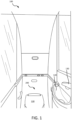
FIG. 1 illustrates a perspective view of a lavatory for an aircraft, in accordance with various embodiments; -
FIG. 2 illustrates a schematic view of a plumbing system for an aircraft, in accordance with various embodiments; -
FIG. 3 illustrates a schematic view of a waste water level detection system, in accordance with various embodiments; and -
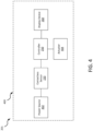
FIG. 4 illustrates a schematic view of a control system for a waste water level detection system, in accordance with various embodiments. - The detailed description of exemplary embodiments herein refers to the accompanying drawings, which show exemplary embodiments by way of illustration and their best mode. While these exemplary embodiments are described in sufficient detail to enable those skilled in the art to practice the disclosure, it should be understood that other embodiments may be realized and that logical, chemical, and mechanical changes may be made without departing from the scope of the appended claims. Thus, the detailed description herein is presented for purposes of illustration only and not of limitation. For example, the steps recited in any of the method or process descriptions may be executed in any order and are not necessarily limited to the order presented. Furthermore, any reference to singular includes plural embodiments, and any reference to more than one component or step may include a singular embodiment or step. Also, any reference to attached, fixed, connected or the like may include permanent, removable, temporary, partial, full and/or any other possible attachment option. Additionally, any reference to without contact (or similar phrases) may also include reduced contact or minimal contact.
- Disclosed herein is waste water level detection systems and method for use in aircrafts. The waste water level detection system comprises a contactless sensor configured to emit a laser beam and receive a return signal from the laser beam within a waste tank to determine a waste water level within the waste tank. The waste water level detection system may reduce a part count of typical systems, increase accuracy relative to typical contact systems, and/or provide continuous monitoring, e, in accordance with various embodiments.
- Referring now to
FIG. 1 , a perspective view of alavatory 100 of an aircraft is illustrated in accordance with various embodiments. Thelavatory 100 comprises atoilet 110, a water basin 120 (e.g., a sink), and afaucet 130. In various embodiments, thelavatory 100 further comprises aplumbing system 200. Theplumbing system 200 is in fluid communication with thetoilet 110, thewater basin 120, and thefaucet 130. In this regard, in response to flushing thetoilet 110, waste water may be transferred throughout theplumbing system 200 as described further herein. Similarly, in response to running water via thefaucet 130, waste water may be transferred throughout theplumbing system 200 as described further herein. - Referring now to
FIG. 2 , aplumbing system 200 comprising a waste waterlevel detection system 201 is illustrated, in accordance with various embodiments. In various embodiments, theplumbing system 200 comprises arinse valve 205 associated with each toilet bowl (e.g.,toilet bowls 203, 204). Therinse valve 205 is configured to open in response to external activation (e.g., via flushing of a handle, via a sensor detecting a person is no longer in front of the sensor, or the like). In response to opening therinse valve 205, waste water may flow (e.g., viafluid conduits 206, 207) from the toilet bowl (e.g.,toilet bowl 203 or toilet bowl 204) to awaste tank 208. In various embodiments, during the flushing process, potable water may be dispensed through apotable water port 209 disposed in each toilet bowl (e.g.,toilet bowls 203, 204). In this regard, any solid waste may be transported from the toilet bowl (e.g.,toilet bowl 203 or toilet bowl 204) to thewaste tank 208 as waste water, in accordance with various embodiments. - In various embodiments, a
contactless sensor 220 is coupled to thewaste tank 208. As described further herein, thecontactless sensor 220 may be disposed within thewaste tank 208, coupled to an external surface of thewaste tank 208, or the like. The present disclosure is not limited in this regard. Thecontactless sensor 220 is in electronic communication with thecontroller 250. - In various embodiments the
contactless sensor 220 is in electronic (i.e., electrical or wireless) communication with acontroller 250. In various embodiments,controller 250 may be integrated into computer system of the aircraft. In various embodiments,controller 250 may be configured as a central network element or hub to access various systems and components of thesystem 201.Controller 250 may comprise a network, computer-based system, and/or software components configured to provide an access point to various systems and components of thesystem 201. In various embodiments,controller 250 may comprise a processor. In various embodiments,controller 250 may be implemented in a single processor. In various embodiments,controller 250 may be implemented as and may include one or more processors and/or one or more tangible, non-transitory memories and be capable of implementing logic. Each processor can be a general purpose processor, a digital signal processor (DSP), an application specific integrated circuit (ASIC), a field programable gate array (FPGA) or other programable logic device, discrete gate or transistor logic, discrete hardware components, or any combination thereof.Controller 250 may comprise a processor configured to implement various logical operations in response to execution of instructions, for example, instructions stored on a non-transitory, tangible, computer-readable medium configured to communicate withcontroller 250. - In various embodiments, the
contactless sensor 220 comprises a laser doppler sensor. Thecontactless sensor 220 may be disposed proximate a top portion of thewaste tank 208. In this regard, thewaste tank 208 may continuously or periodically provide a waste water level in thewaste tank 208 to thecontroller 250. Thus, in response to a waste level exceeding a predetermined threshold (e.g., 90% to 100 % vertical height of the waste water level sensor), thecontroller 250 may send a signal to the display device 260 a waste tank full condition. Thus, the crew may be informed that the waste tank is full and appropriate actions may be taken. In various embodiments, thecontroller 250 may be configured to send a warning signal at a predetermined level (e.g., 80% vertical height of the waste water level sensor) to indicate the waste tank should be emptied soon (i.e., a waste tank near full condition signal). - Referring now to
FIG. 3 , a schematic view of the waste waterlevel detection system 201 is illustrated in accordance with various embodiments. Thesystem 201 comprises thecontactless sensor 220 coupled to thewaste tank 208 of theplumbing system 200 fromFIG. 2 . In various embodiments, thecontactless sensor 220 may be disposed external to thewaste tank 220. For example, atransparent lens 230 may be disposed between a cavity defined by thewaste tank 208 and thecontactless sensor 220. In various embodiments, thetransparent lens 230 is coupled to thewaste tank 208 and thecontactless sensor 220 is coupled to thetransparent lens 230. Although illustrated withtransparent lens 230, the present disclosure is not limited in this regard. For example, thecontactless sensor 220 may be coupled directly to thewaste tank 208 or disposed within thewaste tank 208 and still be within the scope of this disclosure. Although illustrated as being coupled to thetransparent lens 230, the present disclosure is not limited in this regard. For example, thecontactless sensor 220 may be spaced apart from thetransparent lens 230 to facilitate motion of thecontactless sensor 220 during use, in accordance with various embodiments. In various embodiments, thetransparent lens 230 may provide protection from waste water splash, or the like during operation of theplumbing system 200 fromFIG. 2 . - In various embodiments, the
contactless sensor 220 comprises a transceiver. The transceiver is configured to emit a laser beam into thewaste tank 208, receive a return signal of the laser beam, calculate a time from emitting the laser beam to receiving the return signal, and determine a height of waste water within thewaste tank 208 based on the time and a speed of the laser beam. - In various embodiments, the waste water
level detection system 201 is configured to facilitaterotary motion 240 of the contactless sensor 220 (e.g., via a ball and socket joint, or the like) to allow thecontactless sensor 220 to obtain various data points within thewaste tank 208 and/or map a waste water profile within thewaste tank 208. - In various embodiments, the
contactless sensor 220 may prevent any erroneous readings due to clogging of waste from contact sensors (e.g., point level sensors). Additionally, in various embodiments, as multiple contact sensors are typically used for waste water level detection, thecontactless sensor 220 may reduce a sensor count from multiple to one, in accordance with various embodiments. - In various embodiments, the
contactless sensor 220 may provide continuous waste water level data to thecontroller 250. In this regard, thecontroller 250 may be configured to send the waste water level data to thedisplay device 260 to be displayed to any member of the cabin crew. Thus, the waste water level may be continuously monitored, in accordance with various embodiments. - Referring now to
FIG. 4 , a schematic view of acontrol system 400 for thesystem 201 fromFIGs. 2 and3 . In various embodiments, thecontrol system 400 comprises thecontroller 250, thecontactless sensor 220, apower source 402, and thedisplay device 260. Thepower source 402 may be electrically coupled, and configured to power, thecontactless sensor 220. In various embodiments, the power source is a battery, or any other power source disposed on an aircraft. The present disclosure is not limited in this regard. - In various embodiments, the
control system 400 further comprises anactuator 404 electronically (e.g., via a wired connection or wireless connection) thecontroller 250. In this regard, in response to thecontroller 250 determining thewaste tank 208 fromFIG. 2 and3 is full, thecontroller 250 may actuate theactuator 404 to lock a respective lavatory, close arespective valve 205, or the like. In this regard, a lavatory, or toilet may be decommissioned in response to thewaste tank 208 for the respective lavatory or toilet being filled. - Benefits, other advantages, and solutions to problems have been described herein with regard to specific embodiments. Furthermore, the connecting lines shown in the various figures contained herein are intended to represent exemplary functional relationships and/or physical couplings between the various elements. It should be noted that many alternative or additional functional relationships or physical connections may be present in a practical system. However, the benefits, advantages, solutions to problems, and any elements that may cause any benefit, advantage, or solution to occur or become more pronounced are not to be construed as critical, required, or essential features or elements of the disclosure. The scope of the disclosure is accordingly to be limited by nothing other than the appended claims, in which reference to an element in the singular is not intended to mean "one and only one" unless explicitly so stated, but rather "one or more." Moreover, where a phrase similar to "at least one of A, B, or C" is used in the claims, it is intended that the phrase be interpreted to mean that A alone may be present in an embodiment, B alone may be present in an embodiment, C alone may be present in an embodiment, or that any combination of the elements A, B and C may be present in a single embodiment; for example, A and B, A and C, B and C, or A and B and C. Different cross-hatching is used throughout the figures to denote different parts but not necessarily to denote the same or different materials.
- Systems, methods, and apparatus are provided herein. In the detailed description herein, references to "one embodiment", "an embodiment", "an example embodiment", etc., indicate that the embodiment described may include a particular feature, structure, or characteristic, but every embodiment may not necessarily include the particular feature, structure, or characteristic. Moreover, such phrases are not necessarily referring to the same embodiment. Further, when a particular feature, structure, or characteristic is described in connection with an embodiment, it is submitted that it is within the knowledge of one skilled in the art to affect such feature, structure, or characteristic in connection with other embodiments whether or not explicitly described. After reading the description, it will be apparent to one skilled in the relevant art(s) how to implement the disclosure in alternative embodiments.
- Furthermore, no element, component, or method step in the present disclosure is intended to be dedicated to the public regardless of whether the element, component, or method step is explicitly recited in the claims. No claim element herein is to be construed under the provisions of 35 U.S.C. 112 (f) unless the element is expressly recited using the phrase "means for." As used herein, the terms "comprises", "comprising", or any other variation thereof, are intended to cover a non-exclusive inclusion, such that a process, method, article, or apparatus that comprises a list of elements does not include only those elements but may include other elements not expressly listed or inherent to such process, method, article, or apparatus.
Claims (15)
- A system (201), comprising:a contactless sensor (220) configured to couple to a waste tank (208);a controller (250) electronically coupled to the contactless sensor (220), the controller configured to:receive, via the contactless sensor (220), a waste water level data from the contactless sensor (220),calculate a waste water level based on the waste water level data.
- The system of claim 1, further comprising a display device (260) electronically coupled to the controller (250), the controller configured to send the waste water level to the display device (260).
- The system of claim 1 or 2, further comprising the waste tank (208), wherein the waste tank (208) is disposed on an aircraft.
- The system of any preceding claim, further comprising an actuator (404) electronically coupled to the controller (250), the controller (250) configured to actuate the actuator (404) in response to the controller (250) determining the waste water level exceeded a level threshold.
- The system of claim 4, wherein the actuator (404) is configured to lock a lavatory in an aircraft; and/or
wherein the actuator (404) is configured to close a valve (205) disposed between a toilet bowl (203, 204) and the waste tank (208). - The system of any preceding claim, wherein the contactless sensor (220) comprises a laser doppler sensor.
- The system of any preceding claim, further comprising the waste tank (208) and a transparent lens (230), the contactless sensor (220) configured to transmit and receive a laser beam through the transparent lens (230), the transparent lens coupled to the waste tank.
- A plumbing system (200) for an aircraft, comprising:a waste tank (208);a toilet bowl (203, 204);a fluid conduit (206, 207) extending from the waste tank to the toilet bowl;a valve (205) at least partially disposed in the fluid conduit; anda contactless sensor (220) coupled to the waste tank (208), the contactless sensor (220) configured to emit a laser beam into the waste tank (208) and receive a return signal of the laser beam to determine a waste water level in the waste tank (208).
- The plumbing system of claim 8, further comprising a waste water level detection system comprising the contactless sensor (220), the waste water level detection system configured for rotatory motion of the contactless sensor (220), and/or
further comprising a transparent lens (230) coupled to the waste tank, the laser beam configured to travel through the transparent lens. - The plumbing system of claim 8 or 9,
further comprising a controller (250) in electronic communication with the contactless sensor (220), the controller configured to calculate the waste water level in the waste tank based on sensor data from the contactless sensor. - The plumbing system of claim 10, further comprising a display device (260) electronically coupled to the controller (250), the display device (260) configured to display the waste water level in the waste tank; optionally
wherein the controller (250) is configured to send the waste water level in the waste tank to the display device. - The plumbing system of claim 11, further comprising an actuator (404) electronically coupled to the controller (250), the controller (250) configured to actuate the actuator in response to the controller determining a waste water level threshold has been exceeded; optionally
wherein the actuator (404) is configured to at least one of lock a lavatory in the aircraft and close the valve. - An aircraft, comprising:a waste tank (208);a contactless sensor (220) coupled to the waste tank (208), the contactless sensor (220) configured to emit a laser beam into the waste tank (208) and receive a return signal of the laser beam to determine a waste water level in the waste tank; anda controller (250) configured to receive data from the contactless sensor, the controller configured to determine a waste water level based on the data.
- The aircraft of claim 13, wherein the contactless sensor (220) is a laser doppler sensor.
- The aircraft of claim 13 or 14, further comprising a transparent lens (230) coupled to the waste tank (208), the contactless sensor (220) configured to emit the laser beam through the transparent lens (230), and/or
wherein the contactless sensor (220) is disposed external to a cavity defined by the waste tank.
Applications Claiming Priority (2)
| Application Number | Priority Date | Filing Date | Title |
|---|---|---|---|
| IN202141054169 | 2021-11-24 | ||
| US17/846,387 US12018972B2 (en) | 2021-11-24 | 2022-06-22 | Contactless waste tank level sensing systems and methods |
Publications (2)
| Publication Number | Publication Date |
|---|---|
| EP4187212A1 true EP4187212A1 (en) | 2023-05-31 |
| EP4187212B1 EP4187212B1 (en) | 2025-09-03 |
Family
ID=84361495
Family Applications (1)
| Application Number | Title | Priority Date | Filing Date |
|---|---|---|---|
| EP22209090.4A Active EP4187212B1 (en) | 2021-11-24 | 2022-11-23 | Contactless waste tank level sensing systems |
Country Status (1)
| Country | Link |
|---|---|
| EP (1) | EP4187212B1 (en) |
Citations (4)
| Publication number | Priority date | Publication date | Assignee | Title |
|---|---|---|---|---|
| US3995328A (en) * | 1974-12-13 | 1976-12-07 | The Boeing Company | Vacuum toilet system |
| US8424130B2 (en) * | 2009-05-19 | 2013-04-23 | Airbus Operations Gmbh | Toilet monument with receptacle for a mobile sanitary unit |
| US20130232677A1 (en) * | 2005-10-18 | 2013-09-12 | Thetford Corporation | Flush toilet control system and related method |
| US10935413B2 (en) * | 2019-04-10 | 2021-03-02 | The Boeing Company | Non-contact time-of-flight fuel level sensor using plastic optical fiber |
-
2022
- 2022-11-23 EP EP22209090.4A patent/EP4187212B1/en active Active
Patent Citations (4)
| Publication number | Priority date | Publication date | Assignee | Title |
|---|---|---|---|---|
| US3995328A (en) * | 1974-12-13 | 1976-12-07 | The Boeing Company | Vacuum toilet system |
| US20130232677A1 (en) * | 2005-10-18 | 2013-09-12 | Thetford Corporation | Flush toilet control system and related method |
| US8424130B2 (en) * | 2009-05-19 | 2013-04-23 | Airbus Operations Gmbh | Toilet monument with receptacle for a mobile sanitary unit |
| US10935413B2 (en) * | 2019-04-10 | 2021-03-02 | The Boeing Company | Non-contact time-of-flight fuel level sensor using plastic optical fiber |
Also Published As
| Publication number | Publication date |
|---|---|
| EP4187212B1 (en) | 2025-09-03 |
Similar Documents
| Publication | Publication Date | Title |
|---|---|---|
| US10208465B2 (en) | Infra-red control device | |
| US20220030068A1 (en) | Battery powered end point device for iot applications | |
| US12346139B2 (en) | Water level detection via pressure sensing device | |
| US10877493B2 (en) | Monitoring system for monitoring a water level in a plumbing element, and a plumbing element | |
| US12018972B2 (en) | Contactless waste tank level sensing systems and methods | |
| CN203902540U (en) | Ground stationary train toilet discharging sewage treatment device | |
| US12146814B2 (en) | Systems and methods for detecting water leaks and/or preventing waste water overflow | |
| CN107524843B (en) | Urinal detection circuit and detection method thereof | |
| WO2022055889A1 (en) | Automatic sanitaryware assembly and systems | |
| EP4187212B1 (en) | Contactless waste tank level sensing systems | |
| EP4186793A2 (en) | Systems and methods for detecting water leaks and/or preventing waste water overflow | |
| KR102719702B1 (en) | Fault Detecting System for Water Supply and Drainage Facilities | |
| US11959791B2 (en) | Systems and methods for smart point level sensing of waste tank | |
| US8941503B1 (en) | Water saving alarm for use with a toilet tank | |
| ES3023531T3 (en) | Method of detecting probable clogging of outlet | |
| CN208110066U (en) | A kind of long-life high-precision inductive probe system | |
| EP4194820A1 (en) | Systems and methods for smart point level sensing of aircraft waste tank | |
| EP4509877A1 (en) | Touchless lavatory optical time of flight proximity sensor | |
| US20230056884A1 (en) | Ultrasonic sensor based drain systems and methods | |
| JPH10311068A (en) | Building water supply management system | |
| CN108100261A (en) | Aircraft airborne foul water system and sewage discharge method | |
| RU121783U1 (en) | SANITARY TECHNICAL EQUIPMENT OF PASSENGER CAR | |
| TW201348560A (en) | Wastewater anti-overflow and warning device | |
| EP3705895A1 (en) | Urinal sensor system | |
| US20250034849A1 (en) | Sensor arrangement for detecting a person in an area of use of a sanitary facility |
Legal Events
| Date | Code | Title | Description |
|---|---|---|---|
| PUAI | Public reference made under article 153(3) epc to a published international application that has entered the european phase |
Free format text: ORIGINAL CODE: 0009012 |
|
| STAA | Information on the status of an ep patent application or granted ep patent |
Free format text: STATUS: THE APPLICATION HAS BEEN PUBLISHED |
|
| AK | Designated contracting states |
Kind code of ref document: A1 Designated state(s): AL AT BE BG CH CY CZ DE DK EE ES FI FR GB GR HR HU IE IS IT LI LT LU LV MC ME MK MT NL NO PL PT RO RS SE SI SK SM TR |
|
| P01 | Opt-out of the competence of the unified patent court (upc) registered |
Effective date: 20230922 |
|
| STAA | Information on the status of an ep patent application or granted ep patent |
Free format text: STATUS: REQUEST FOR EXAMINATION WAS MADE |
|
| 17P | Request for examination filed |
Effective date: 20231127 |
|
| RBV | Designated contracting states (corrected) |
Designated state(s): AL AT BE BG CH CY CZ DE DK EE ES FI FR GB GR HR HU IE IS IT LI LT LU LV MC ME MK MT NL NO PL PT RO RS SE SI SK SM TR |
|
| GRAP | Despatch of communication of intention to grant a patent |
Free format text: ORIGINAL CODE: EPIDOSNIGR1 |
|
| STAA | Information on the status of an ep patent application or granted ep patent |
Free format text: STATUS: GRANT OF PATENT IS INTENDED |
|
| INTG | Intention to grant announced |
Effective date: 20241111 |
|
| GRAJ | Information related to disapproval of communication of intention to grant by the applicant or resumption of examination proceedings by the epo deleted |
Free format text: ORIGINAL CODE: EPIDOSDIGR1 |
|
| STAA | Information on the status of an ep patent application or granted ep patent |
Free format text: STATUS: REQUEST FOR EXAMINATION WAS MADE |
|
| GRAP | Despatch of communication of intention to grant a patent |
Free format text: ORIGINAL CODE: EPIDOSNIGR1 |
|
| STAA | Information on the status of an ep patent application or granted ep patent |
Free format text: STATUS: GRANT OF PATENT IS INTENDED |
|
| INTC | Intention to grant announced (deleted) | ||
| INTG | Intention to grant announced |
Effective date: 20250324 |
|
| GRAS | Grant fee paid |
Free format text: ORIGINAL CODE: EPIDOSNIGR3 |
|
| GRAA | (expected) grant |
Free format text: ORIGINAL CODE: 0009210 |
|
| STAA | Information on the status of an ep patent application or granted ep patent |
Free format text: STATUS: THE PATENT HAS BEEN GRANTED |
|
| AK | Designated contracting states |
Kind code of ref document: B1 Designated state(s): AL AT BE BG CH CY CZ DE DK EE ES FI FR GB GR HR HU IE IS IT LI LT LU LV MC ME MK MT NL NO PL PT RO RS SE SI SK SM TR |
|
| REG | Reference to a national code |
Ref country code: CH Ref legal event code: EP |
|
| REG | Reference to a national code |
Ref country code: DE Ref legal event code: R096 Ref document number: 602022020664 Country of ref document: DE |
|
| REG | Reference to a national code |
Ref country code: IE Ref legal event code: FG4D |
|
| REG | Reference to a national code |
Ref country code: NL Ref legal event code: MP Effective date: 20250903 |
|
| PGFP | Annual fee paid to national office [announced via postgrant information from national office to epo] |
Ref country code: DE Payment date: 20251022 Year of fee payment: 4 |
|
| PG25 | Lapsed in a contracting state [announced via postgrant information from national office to epo] |
Ref country code: NO Free format text: LAPSE BECAUSE OF FAILURE TO SUBMIT A TRANSLATION OF THE DESCRIPTION OR TO PAY THE FEE WITHIN THE PRESCRIBED TIME-LIMIT Effective date: 20251203 |
|
| REG | Reference to a national code |
Ref country code: LT Ref legal event code: MG9D |
|
| PG25 | Lapsed in a contracting state [announced via postgrant information from national office to epo] |
Ref country code: FI Free format text: LAPSE BECAUSE OF FAILURE TO SUBMIT A TRANSLATION OF THE DESCRIPTION OR TO PAY THE FEE WITHIN THE PRESCRIBED TIME-LIMIT Effective date: 20250903 |
|
| PG25 | Lapsed in a contracting state [announced via postgrant information from national office to epo] |
Ref country code: HR Free format text: LAPSE BECAUSE OF FAILURE TO SUBMIT A TRANSLATION OF THE DESCRIPTION OR TO PAY THE FEE WITHIN THE PRESCRIBED TIME-LIMIT Effective date: 20250903 |
|
| PGFP | Annual fee paid to national office [announced via postgrant information from national office to epo] |
Ref country code: FR Payment date: 20251022 Year of fee payment: 4 |
|
| PG25 | Lapsed in a contracting state [announced via postgrant information from national office to epo] |
Ref country code: GR Free format text: LAPSE BECAUSE OF FAILURE TO SUBMIT A TRANSLATION OF THE DESCRIPTION OR TO PAY THE FEE WITHIN THE PRESCRIBED TIME-LIMIT Effective date: 20251204 |
|
| PG25 | Lapsed in a contracting state [announced via postgrant information from national office to epo] |
Ref country code: SE Free format text: LAPSE BECAUSE OF FAILURE TO SUBMIT A TRANSLATION OF THE DESCRIPTION OR TO PAY THE FEE WITHIN THE PRESCRIBED TIME-LIMIT Effective date: 20250903 |
|
| PG25 | Lapsed in a contracting state [announced via postgrant information from national office to epo] |
Ref country code: LV Free format text: LAPSE BECAUSE OF FAILURE TO SUBMIT A TRANSLATION OF THE DESCRIPTION OR TO PAY THE FEE WITHIN THE PRESCRIBED TIME-LIMIT Effective date: 20250903 |
|
| PG25 | Lapsed in a contracting state [announced via postgrant information from national office to epo] |
Ref country code: BG Free format text: LAPSE BECAUSE OF FAILURE TO SUBMIT A TRANSLATION OF THE DESCRIPTION OR TO PAY THE FEE WITHIN THE PRESCRIBED TIME-LIMIT Effective date: 20250903 Ref country code: PL Free format text: LAPSE BECAUSE OF FAILURE TO SUBMIT A TRANSLATION OF THE DESCRIPTION OR TO PAY THE FEE WITHIN THE PRESCRIBED TIME-LIMIT Effective date: 20250903 |
|
| PG25 | Lapsed in a contracting state [announced via postgrant information from national office to epo] |
Ref country code: RS Free format text: LAPSE BECAUSE OF FAILURE TO SUBMIT A TRANSLATION OF THE DESCRIPTION OR TO PAY THE FEE WITHIN THE PRESCRIBED TIME-LIMIT Effective date: 20251203 |
|
| PG25 | Lapsed in a contracting state [announced via postgrant information from national office to epo] |
Ref country code: ES Free format text: LAPSE BECAUSE OF FAILURE TO SUBMIT A TRANSLATION OF THE DESCRIPTION OR TO PAY THE FEE WITHIN THE PRESCRIBED TIME-LIMIT Effective date: 20250903 |
|
| REG | Reference to a national code |
Ref country code: AT Ref legal event code: MK05 Ref document number: 1833548 Country of ref document: AT Kind code of ref document: T Effective date: 20250903 |
|
| PG25 | Lapsed in a contracting state [announced via postgrant information from national office to epo] |
Ref country code: NL Free format text: LAPSE BECAUSE OF FAILURE TO SUBMIT A TRANSLATION OF THE DESCRIPTION OR TO PAY THE FEE WITHIN THE PRESCRIBED TIME-LIMIT Effective date: 20250903 |
|
| PG25 | Lapsed in a contracting state [announced via postgrant information from national office to epo] |
Ref country code: SM Free format text: LAPSE BECAUSE OF FAILURE TO SUBMIT A TRANSLATION OF THE DESCRIPTION OR TO PAY THE FEE WITHIN THE PRESCRIBED TIME-LIMIT Effective date: 20250903 |
|
| PG25 | Lapsed in a contracting state [announced via postgrant information from national office to epo] |
Ref country code: AT Free format text: LAPSE BECAUSE OF FAILURE TO SUBMIT A TRANSLATION OF THE DESCRIPTION OR TO PAY THE FEE WITHIN THE PRESCRIBED TIME-LIMIT Effective date: 20250903 |
|
| PG25 | Lapsed in a contracting state [announced via postgrant information from national office to epo] |
Ref country code: RO Free format text: LAPSE BECAUSE OF FAILURE TO SUBMIT A TRANSLATION OF THE DESCRIPTION OR TO PAY THE FEE WITHIN THE PRESCRIBED TIME-LIMIT Effective date: 20250903 Ref country code: IT Free format text: LAPSE BECAUSE OF FAILURE TO SUBMIT A TRANSLATION OF THE DESCRIPTION OR TO PAY THE FEE WITHIN THE PRESCRIBED TIME-LIMIT Effective date: 20250903 |
|
| PG25 | Lapsed in a contracting state [announced via postgrant information from national office to epo] |
Ref country code: IS Free format text: LAPSE BECAUSE OF FAILURE TO SUBMIT A TRANSLATION OF THE DESCRIPTION OR TO PAY THE FEE WITHIN THE PRESCRIBED TIME-LIMIT Effective date: 20260103 |
|
| PG25 | Lapsed in a contracting state [announced via postgrant information from national office to epo] |
Ref country code: CZ Free format text: LAPSE BECAUSE OF FAILURE TO SUBMIT A TRANSLATION OF THE DESCRIPTION OR TO PAY THE FEE WITHIN THE PRESCRIBED TIME-LIMIT Effective date: 20250903 Ref country code: PT Free format text: LAPSE BECAUSE OF FAILURE TO SUBMIT A TRANSLATION OF THE DESCRIPTION OR TO PAY THE FEE WITHIN THE PRESCRIBED TIME-LIMIT Effective date: 20260105 |
|
| PG25 | Lapsed in a contracting state [announced via postgrant information from national office to epo] |
Ref country code: EE Free format text: LAPSE BECAUSE OF FAILURE TO SUBMIT A TRANSLATION OF THE DESCRIPTION OR TO PAY THE FEE WITHIN THE PRESCRIBED TIME-LIMIT Effective date: 20250903 Ref country code: SK Free format text: LAPSE BECAUSE OF FAILURE TO SUBMIT A TRANSLATION OF THE DESCRIPTION OR TO PAY THE FEE WITHIN THE PRESCRIBED TIME-LIMIT Effective date: 20250903 |