EP4187171A1 - Continuous-flow heater - Google Patents
Continuous-flow heater Download PDFInfo
- Publication number
- EP4187171A1 EP4187171A1 EP21461624.5A EP21461624A EP4187171A1 EP 4187171 A1 EP4187171 A1 EP 4187171A1 EP 21461624 A EP21461624 A EP 21461624A EP 4187171 A1 EP4187171 A1 EP 4187171A1
- Authority
- EP
- European Patent Office
- Prior art keywords
- continuous
- closure element
- flow heater
- channel
- heater according
- Prior art date
- Legal status (The legal status is an assumption and is not a legal conclusion. Google has not performed a legal analysis and makes no representation as to the accuracy of the status listed.)
- Granted
Links
Images

Classifications
-
- F—MECHANICAL ENGINEERING; LIGHTING; HEATING; WEAPONS; BLASTING
- F24—HEATING; RANGES; VENTILATING
- F24H—FLUID HEATERS, e.g. WATER OR AIR HEATERS, HAVING HEAT-GENERATING MEANS, e.g. HEAT PUMPS, IN GENERAL
- F24H1/00—Water heaters, e.g. boilers, continuous-flow heaters or water-storage heaters
- F24H1/10—Continuous-flow heaters, i.e. heaters in which heat is generated only while the water is flowing, e.g. with direct contact of the water with the heating medium
- F24H1/12—Continuous-flow heaters, i.e. heaters in which heat is generated only while the water is flowing, e.g. with direct contact of the water with the heating medium in which the water is kept separate from the heating medium
- F24H1/121—Continuous-flow heaters, i.e. heaters in which heat is generated only while the water is flowing, e.g. with direct contact of the water with the heating medium in which the water is kept separate from the heating medium using electric energy supply
-
- F—MECHANICAL ENGINEERING; LIGHTING; HEATING; WEAPONS; BLASTING
- F24—HEATING; RANGES; VENTILATING
- F24H—FLUID HEATERS, e.g. WATER OR AIR HEATERS, HAVING HEAT-GENERATING MEANS, e.g. HEAT PUMPS, IN GENERAL
- F24H9/00—Details
- F24H9/20—Arrangement or mounting of control or safety devices
- F24H9/2007—Arrangement or mounting of control or safety devices for water heaters
- F24H9/2014—Arrangement or mounting of control or safety devices for water heaters using electrical energy supply
- F24H9/2028—Continuous-flow heaters
-
- F—MECHANICAL ENGINEERING; LIGHTING; HEATING; WEAPONS; BLASTING
- F24—HEATING; RANGES; VENTILATING
- F24D—DOMESTIC- OR SPACE-HEATING SYSTEMS, e.g. CENTRAL HEATING SYSTEMS; DOMESTIC HOT-WATER SUPPLY SYSTEMS; ELEMENTS OR COMPONENTS THEREFOR
- F24D2200/00—Heat sources or energy sources
- F24D2200/16—Waste heat
- F24D2200/29—Electrical devices, e.g. computers, servers
Definitions
- the invention relates to continuous-flow heater according to the preamble of patent claim 1.
- a continuous-flow heater of the type mentioned at the beginning is known from the document EP 2 489 956 B1 .
- a continuous-flow heater which has a body and a channel extending in the body and carrying water.
- An opening forming an access to the channel and closed by a closure element is provided on the body, wherein the closure element has a heat transfer region arranged in the region of the opening and being in contact with the water.
- a continuous-flow heater constructed in a particularly simple manner is to be created.
- the closure element is formed to be plate-shaped. It is particularly preferred that the closure element is also provided with a stamping forming the heat transfer region.
- the continuous-flow heater according to the invention is thus characterized in that the closure element and the heat transfer region are formed in one piece by bending or, preferably, stamping.
- the continuous-flow heater can be manufactured in a particularly simple and cost-effective manner while still maintaining high energy efficiency.
- the closure element has a projection extending into the opening and comprising the heat transfer region. It is thus provided that the closure element is bulged into the opening, which has the additional advantage that, on the one hand, a large heat transfer region is created, and, on the other hand, the bulge also provides for stiffening of the closure element.
- the continuous-flow heater shown in the figures initially consists in a known manner of, among other things, a body 1 and a water-carrying channel 2 extending in the body 1.
- an opening 4 forming an access to the channel 2 and closed by a closure element 3 is provided on the body 1, wherein the closure element 3 has a heat transfer region 3.1 arranged in the region of the opening 4 and being in contact with the water.
- closure element 3 is formed to be plate-shaped and, particularly preferably (compare Figures 1 to 5 ), is provided with a stamping forming the heat transfer region 3.1.
- Figures 6 and 7 show a solution according to the invention without the mentioned stamping.
- the heat transfer region 3.1, on the one hand, and an arrangement region 3.2 for an electronic component 5, on the other hand, are provided on the closure element 3.
- at least one heat-emitting electronic component 5 is arranged on the closure element 3. Fixing the component 5 to the closure element 3 is preferably carried out by means of a spring-loaded clamping strip (not shown separately).
- the electronic component 5 is arranged directly on the heat transfer region 3.1.
- heat released by the electronic component 5 can thus be dissipated via the closure element 3 directly to the water flowing through the channel 2.
- the water-carrying channel 2 is arranged between a cold water connection and an electrical heating device (the cold water connection and the heating device are not shown separately). This measure ensures that the electronic component 5 comes into contact with the coldest water available in the continuous-flow heater and in this way can dissipate as much heat as possible or be cooled as well as possible.
- the opening 4 is formed to be elongated and to extend along the channel 2. More precisely, it is provided in a particularly preferred manner that a length of the opening 4 extending along the channel 2 corresponds to at least three times a width of the channel 2.
- the stamping forming the heat transfer region 3.1 is formed extending over the entire opening 4.
- the channel 2 is formed to be unobstructed by the heat transfer region 3.1.
- the closure element 3 is formed from metal.
- the body 1 is preferably formed from plastics. Furthermore, it is preferably provided that a sealing element 6, which preferably completely encloses the opening 4, is arranged between the body 1 and the closure element 3.
- the body 1 and the closure element 3, in particular a fastening region 3.3 of the closure element 3, are formed to be screwed together (preferably with self-tapping screws).
- the heat transfer region 3.1 is preferably located completely within the fastening region 3.3.
- the arrangement region 3.2 is formed with a flat surface.
- the arrangement region 3.2 in the solution according to Figures 1 to 5 is formed at an angle to the fastening region 3.3 of the closure element 3.
- the heat transfer region 3.1 and the arrangement region 3.2 practically coincide.
Landscapes
- Engineering & Computer Science (AREA)
- Physics & Mathematics (AREA)
- Thermal Sciences (AREA)
- Chemical & Material Sciences (AREA)
- Combustion & Propulsion (AREA)
- Mechanical Engineering (AREA)
- General Engineering & Computer Science (AREA)
- Instantaneous Water Boilers, Portable Hot-Water Supply Apparatuses, And Control Of Portable Hot-Water Supply Apparatuses (AREA)
Abstract
Description
- The invention relates to continuous-flow heater according to the preamble of
patent claim 1. - A continuous-flow heater of the type mentioned at the beginning is known from the
document EP 2 489 956 B1 . There, a continuous-flow heater is shown which has a body and a channel extending in the body and carrying water. An opening forming an access to the channel and closed by a closure element is provided on the body, wherein the closure element has a heat transfer region arranged in the region of the opening and being in contact with the water. - It is the object of the invention to improve a continuous-flow heater of the type mentioned above. In particular, a continuous-flow heater constructed in a particularly simple manner is to be created.
- This object is achieved with a continuous-flow heater of the type mentioned above by the features listed in the characterizing part of
patent claim 1. - According to the invention, it is thus provided that the closure element is formed to be plate-shaped. It is particularly preferred that the closure element is also provided with a stamping forming the heat transfer region.
- In other words, the continuous-flow heater according to the invention is thus characterized in that the closure element and the heat transfer region are formed in one piece by bending or, preferably, stamping. As a result, the continuous-flow heater can be manufactured in a particularly simple and cost-effective manner while still maintaining high energy efficiency.
- Again in other words, it is thus particularly preferably provided that the closure element has a projection extending into the opening and comprising the heat transfer region. It is thus provided that the closure element is bulged into the opening, which has the additional advantage that, on the one hand, a large heat transfer region is created, and, on the other hand, the bulge also provides for stiffening of the closure element.
- Other advantageous refinements of the continuous-flow heater according to the invention arise from the dependent patent claims.
- For the sake of completeness, reference is also made to the document
US 6,892,796 B1 . - The continuous-flow heater according to the invention, including its advantageous refinements according to the dependent patent claims, is explained in more detail below by means of the graphic representation of two preferred exemplary embodiments.
- In the figures
- Figure 1
- shows a cross-section of a first embodiment of the continuous-flow heater according to the invention with its body and the closure element;
- Figure 2
- shows a perspective view of the continuous-flow heater shown in
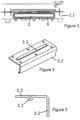
Figure 1 with a total of four electronic components; - Figure 3
- shows a top view of the continuous-flow heater according to
Figure 1 with theclosure element 3 removed, looking into thechannel 2; - Figure 4
- shows a perspective view of the closure element according to
Figure 1 (without the electronic components); - Figure 5
- shows a cross-section of the closure element according to
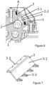
Figure 4 ; - Figure 6
- shows a cross-section of a second, particularly simple embodiment of the continuous-flow heater according to the invention with the closure element, but without the particularly preferred stamping; and
- Figure 7
- shows a perspective view of the closure element according to
Figure 6 (again without the electronic components) . - The continuous-flow heater shown in the figures initially consists in a known manner of, among other things, a
body 1 and a water-carryingchannel 2 extending in thebody 1. In this connection, anopening 4 forming an access to thechannel 2 and closed by aclosure element 3 is provided on thebody 1, wherein theclosure element 3 has a heat transfer region 3.1 arranged in the region of theopening 4 and being in contact with the water. - It is essential for the continuous-flow heater according to the invention that the
closure element 3 is formed to be plate-shaped and, particularly preferably (compareFigures 1 to 5 ), is provided with a stamping forming the heat transfer region 3.1.Figures 6 and 7 show a solution according to the invention without the mentioned stamping. - As can be seen from
Figures 1 and 2 , it is provided in a particularly preferred manner that the heat transfer region 3.1, on the one hand, and an arrangement region 3.2 for anelectronic component 5, on the other hand, are provided on theclosure element 3. In more concrete terms, it is thus preferably provided that at least one heat-emittingelectronic component 5 is arranged on theclosure element 3. Fixing thecomponent 5 to theclosure element 3 is preferably carried out by means of a spring-loaded clamping strip (not shown separately). In the solution according toFigures 6 and 7 , theelectronic component 5 is arranged directly on the heat transfer region 3.1. - As is readily apparent in particular from
Figures 1 and6 , heat released by theelectronic component 5 can thus be dissipated via theclosure element 3 directly to the water flowing through thechannel 2. - It is further particularly preferred here that the water-carrying
channel 2 is arranged between a cold water connection and an electrical heating device (the cold water connection and the heating device are not shown separately). This measure ensures that theelectronic component 5 comes into contact with the coldest water available in the continuous-flow heater and in this way can dissipate as much heat as possible or be cooled as well as possible. - As can be seen in particular from
Figure 3 (but can ultimately also be derived fromFigure 7 ), it is preferably provided that for a particularly intensive heat transfer, theopening 4 is formed to be elongated and to extend along thechannel 2. More precisely, it is provided in a particularly preferred manner that a length of the opening 4 extending along thechannel 2 corresponds to at least three times a width of thechannel 2. - Furthermore, in order to improve the heat transfer, but also to increase the pressure stability of the
closure element 3 in the solution according toFigures 1 to 5 , it is preferably provided that the stamping forming the heat transfer region 3.1 is formed extending over theentire opening 4. In addition, it is preferred that thechannel 2 is formed to be unobstructed by the heat transfer region 3.1. - Furthermore, it is preferably provided that the
closure element 3 is formed from metal. - A further particularity is that the
body 1 is preferably formed from plastics. Furthermore, it is preferably provided that asealing element 6, which preferably completely encloses theopening 4, is arranged between thebody 1 and theclosure element 3. - To implement a simple assembly, it is further preferably provided that the
body 1 and theclosure element 3, in particular a fastening region 3.3 of theclosure element 3, are formed to be screwed together (preferably with self-tapping screws). In this case, the heat transfer region 3.1 is preferably located completely within the fastening region 3.3. - Furthermore, with reference in particular to
Figures 4 and 5 , it is preferably provided that the arrangement region 3.2 is formed with a flat surface. Finally, it is also preferably provided that the arrangement region 3.2 in the solution according toFigures 1 to 5 is formed at an angle to the fastening region 3.3 of theclosure element 3. As already stated above, in the solution according toFigures 6 and 7 , the heat transfer region 3.1 and the arrangement region 3.2 practically coincide. -
- 1
- body
- 2
- channel
- 3
- closure element
- 3.1
- heat transfer region
- 3.2
- arrangement region
- 3.3
- fastening region
- 4
- opening
- 5
- electronic component
- 6
- sealing element
Claims (10)
- A continuous-flow heater comprising a body (1) and a channel (2) extending in the body (1) and carrying water, wherein an opening (4) forming an access to the channel (2) and closed by a closure element (3) is provided on the body (1), wherein the closure element (3) has a heat transfer region (3.1) arranged in the region of the opening (4) and being in contact with the water,
characterized in
that the closure element (3) is formed to be plate-shaped. - The continuous-flow heater according to claim 1,
characterized in
that the plate-shaped closure element (3) is formed to be provided with a stamping forming the heat transfer region (3.1). - The continuous-flow heater according to claim 1 or 2,
characterized in
that the opening (4) is formed elongated and extending along the channel (2). - The continuous-flow heater according to any one of claims 1 to 3,
characterized in
that a length of the opening (4) extending along the channel (2) corresponds to at least three times a width of the channel (2). - The continuous-flow heater according to any one of claims 1 to 4,
characterized in
that the stamping forming the heat transfer region (3.1) is formed extending over the entire opening (4). - The continuous-flow heater according to any one of claims 1 to 5,
characterized in
that the heat transfer region (3.1), on the one hand, and an arrangement region (3.2) for an electronic component (5), on the other hand, are provided on the closure element (3). - The continuous-flow heater according to any one of claims 1 to 6,
characterized in
that a heat-emitting electronic component (5) is arranged on the closure element (3). - The continuous-flow heater according to any one of claims 1 to 7,
characterized in
that the water-carrying channel (2) is arranged between a cold water connection and an electric heating device. - The continuous-flow heater according to any one of claims 1 to 8,
characterized in
that the closure element (3) is formed from metal. - The continuous-flow heater according to any one of claims 1 to 9,
characterized in
that a sealing element (6) preferably completely enclosing the opening (4) is arranged between the body (1) and the closure element (3).
Priority Applications (1)
| Application Number | Priority Date | Filing Date | Title |
|---|---|---|---|
| EP21461624.5A EP4187171B1 (en) | 2021-11-26 | 2021-11-26 | Continuous-flow heater |
Applications Claiming Priority (1)
| Application Number | Priority Date | Filing Date | Title |
|---|---|---|---|
| EP21461624.5A EP4187171B1 (en) | 2021-11-26 | 2021-11-26 | Continuous-flow heater |
Publications (2)
| Publication Number | Publication Date |
|---|---|
| EP4187171A1 true EP4187171A1 (en) | 2023-05-31 |
| EP4187171B1 EP4187171B1 (en) | 2025-07-02 |
Family
ID=78819439
Family Applications (1)
| Application Number | Title | Priority Date | Filing Date |
|---|---|---|---|
| EP21461624.5A Active EP4187171B1 (en) | 2021-11-26 | 2021-11-26 | Continuous-flow heater |
Country Status (1)
| Country | Link |
|---|---|
| EP (1) | EP4187171B1 (en) |
Citations (5)
| Publication number | Priority date | Publication date | Assignee | Title |
|---|---|---|---|---|
| US6892796B1 (en) | 2000-02-23 | 2005-05-17 | General Motors Corporation | Apparatus and method for mounting a power module |
| DE102012207305A1 (en) * | 2012-05-02 | 2013-11-07 | Webasto Ag | A heater for a vehicle and method of operating the heater |
| WO2014005708A1 (en) * | 2012-07-06 | 2014-01-09 | Stiebel Eltron Gmbh & Co. Kg | Heating block for heating water |
| DE102013021286A1 (en) * | 2013-12-19 | 2015-06-25 | Stiebel Eltron Gmbh & Co. Kg | heating block |
| EP2489956B1 (en) | 2011-02-21 | 2017-04-05 | Gerdes OHG | Cooling system of an electric construction element that heats up |
-
2021
- 2021-11-26 EP EP21461624.5A patent/EP4187171B1/en active Active
Patent Citations (5)
| Publication number | Priority date | Publication date | Assignee | Title |
|---|---|---|---|---|
| US6892796B1 (en) | 2000-02-23 | 2005-05-17 | General Motors Corporation | Apparatus and method for mounting a power module |
| EP2489956B1 (en) | 2011-02-21 | 2017-04-05 | Gerdes OHG | Cooling system of an electric construction element that heats up |
| DE102012207305A1 (en) * | 2012-05-02 | 2013-11-07 | Webasto Ag | A heater for a vehicle and method of operating the heater |
| WO2014005708A1 (en) * | 2012-07-06 | 2014-01-09 | Stiebel Eltron Gmbh & Co. Kg | Heating block for heating water |
| DE102013021286A1 (en) * | 2013-12-19 | 2015-06-25 | Stiebel Eltron Gmbh & Co. Kg | heating block |
Also Published As
| Publication number | Publication date |
|---|---|
| EP4187171B1 (en) | 2025-07-02 |
Similar Documents
| Publication | Publication Date | Title |
|---|---|---|
| US9646912B2 (en) | Semiconductor device and semiconductor module having cooling fins | |
| EP1721343B1 (en) | Improvements in or relating to thermoelectric heat pumps | |
| JP6109265B2 (en) | Electric equipment with refrigerant flow path | |
| JP5333161B2 (en) | heatsink | |
| US20080029251A1 (en) | Water-cooled heat sink and water-cooled system | |
| US7701712B2 (en) | Cooling unit | |
| EP4187171B1 (en) | Continuous-flow heater | |
| EP3299743B1 (en) | Electric heater | |
| CN115087147A (en) | Electric heating device | |
| US20220201899A1 (en) | Electric appliance having a housing part | |
| CN100543644C (en) | Cooling device | |
| US7278467B2 (en) | Liquid-cooled heat radiator kit | |
| US9338827B2 (en) | Heating device for installation in a switchgear cabinet | |
| KR20190073667A (en) | PTC heater | |
| CN219693969U (en) | Radiating plate and radiator | |
| KR200235545Y1 (en) | a cooling sash for a PCB | |
| JP2004104035A (en) | Heat sink with fan | |
| CN209184914U (en) | Device for controlling power tool | |
| US20050039880A1 (en) | Computer cooling apparatus | |
| DE102005001748B4 (en) | Electric switch and electric hand tool with such a switch | |
| KR200311730Y1 (en) | Pre-Heater for cooling water in vehicle | |
| CN211090360U (en) | Heat sink device | |
| CN216673625U (en) | Cooler and electrical equipment | |
| US20240274488A1 (en) | Thermal conductive member for a heat sink | |
| EP2570881B2 (en) | Temperature control device, particularly a thermostatic device |
Legal Events
| Date | Code | Title | Description |
|---|---|---|---|
| PUAI | Public reference made under article 153(3) epc to a published international application that has entered the european phase |
Free format text: ORIGINAL CODE: 0009012 |
|
| STAA | Information on the status of an ep patent application or granted ep patent |
Free format text: STATUS: THE APPLICATION HAS BEEN PUBLISHED |
|
| AK | Designated contracting states |
Kind code of ref document: A1 Designated state(s): AL AT BE BG CH CY CZ DE DK EE ES FI FR GB GR HR HU IE IS IT LI LT LU LV MC MK MT NL NO PL PT RO RS SE SI SK SM TR |
|
| STAA | Information on the status of an ep patent application or granted ep patent |
Free format text: STATUS: REQUEST FOR EXAMINATION WAS MADE |
|
| 17P | Request for examination filed |
Effective date: 20231115 |
|
| RBV | Designated contracting states (corrected) |
Designated state(s): AL AT BE BG CH CY CZ DE DK EE ES FI FR GB GR HR HU IE IS IT LI LT LU LV MC MK MT NL NO PL PT RO RS SE SI SK SM TR |
|
| RAP1 | Party data changed (applicant data changed or rights of an application transferred) |
Owner name: KOSPEL SPOLKA Z O.O. |
|
| GRAP | Despatch of communication of intention to grant a patent |
Free format text: ORIGINAL CODE: EPIDOSNIGR1 |
|
| STAA | Information on the status of an ep patent application or granted ep patent |
Free format text: STATUS: GRANT OF PATENT IS INTENDED |
|
| INTG | Intention to grant announced |
Effective date: 20250129 |
|
| GRAS | Grant fee paid |
Free format text: ORIGINAL CODE: EPIDOSNIGR3 |
|
| GRAA | (expected) grant |
Free format text: ORIGINAL CODE: 0009210 |
|
| STAA | Information on the status of an ep patent application or granted ep patent |
Free format text: STATUS: THE PATENT HAS BEEN GRANTED |
|
| AK | Designated contracting states |
Kind code of ref document: B1 Designated state(s): AL AT BE BG CH CY CZ DE DK EE ES FI FR GB GR HR HU IE IS IT LI LT LU LV MC MK MT NL NO PL PT RO RS SE SI SK SM TR |
|
| REG | Reference to a national code |
Ref country code: GB Ref legal event code: FG4D |
|
| REG | Reference to a national code |
Ref country code: CH Ref legal event code: EP |
|
| REG | Reference to a national code |
Ref country code: DE Ref legal event code: R096 Ref document number: 602021033272 Country of ref document: DE |
|
| REG | Reference to a national code |
Ref country code: IE Ref legal event code: FG4D |
|
| REG | Reference to a national code |
Ref country code: NL Ref legal event code: MP Effective date: 20250702 |
|
| PG25 | Lapsed in a contracting state [announced via postgrant information from national office to epo] |
Ref country code: PT Free format text: LAPSE BECAUSE OF FAILURE TO SUBMIT A TRANSLATION OF THE DESCRIPTION OR TO PAY THE FEE WITHIN THE PRESCRIBED TIME-LIMIT Effective date: 20251103 |
|
| PG25 | Lapsed in a contracting state [announced via postgrant information from national office to epo] |
Ref country code: NL Free format text: LAPSE BECAUSE OF FAILURE TO SUBMIT A TRANSLATION OF THE DESCRIPTION OR TO PAY THE FEE WITHIN THE PRESCRIBED TIME-LIMIT Effective date: 20250702 |
|
| REG | Reference to a national code |
Ref country code: AT Ref legal event code: MK05 Ref document number: 1809613 Country of ref document: AT Kind code of ref document: T Effective date: 20250702 |
|
| PG25 | Lapsed in a contracting state [announced via postgrant information from national office to epo] |
Ref country code: IS Free format text: LAPSE BECAUSE OF FAILURE TO SUBMIT A TRANSLATION OF THE DESCRIPTION OR TO PAY THE FEE WITHIN THE PRESCRIBED TIME-LIMIT Effective date: 20251102 |
|
| PGFP | Annual fee paid to national office [announced via postgrant information from national office to epo] |
Ref country code: DE Payment date: 20251203 Year of fee payment: 5 |
|
| PG25 | Lapsed in a contracting state [announced via postgrant information from national office to epo] |
Ref country code: NO Free format text: LAPSE BECAUSE OF FAILURE TO SUBMIT A TRANSLATION OF THE DESCRIPTION OR TO PAY THE FEE WITHIN THE PRESCRIBED TIME-LIMIT Effective date: 20251002 |
|
| REG | Reference to a national code |
Ref country code: LT Ref legal event code: MG9D |
|
| PG25 | Lapsed in a contracting state [announced via postgrant information from national office to epo] |
Ref country code: AT Free format text: LAPSE BECAUSE OF FAILURE TO SUBMIT A TRANSLATION OF THE DESCRIPTION OR TO PAY THE FEE WITHIN THE PRESCRIBED TIME-LIMIT Effective date: 20250702 |
|
| PG25 | Lapsed in a contracting state [announced via postgrant information from national office to epo] |
Ref country code: FI Free format text: LAPSE BECAUSE OF FAILURE TO SUBMIT A TRANSLATION OF THE DESCRIPTION OR TO PAY THE FEE WITHIN THE PRESCRIBED TIME-LIMIT Effective date: 20250702 |
|
| PG25 | Lapsed in a contracting state [announced via postgrant information from national office to epo] |
Ref country code: HR Free format text: LAPSE BECAUSE OF FAILURE TO SUBMIT A TRANSLATION OF THE DESCRIPTION OR TO PAY THE FEE WITHIN THE PRESCRIBED TIME-LIMIT Effective date: 20250702 |
|
| PG25 | Lapsed in a contracting state [announced via postgrant information from national office to epo] |
Ref country code: GR Free format text: LAPSE BECAUSE OF FAILURE TO SUBMIT A TRANSLATION OF THE DESCRIPTION OR TO PAY THE FEE WITHIN THE PRESCRIBED TIME-LIMIT Effective date: 20251003 |
|
| PG25 | Lapsed in a contracting state [announced via postgrant information from national office to epo] |
Ref country code: SE Free format text: LAPSE BECAUSE OF FAILURE TO SUBMIT A TRANSLATION OF THE DESCRIPTION OR TO PAY THE FEE WITHIN THE PRESCRIBED TIME-LIMIT Effective date: 20250702 Ref country code: CZ Free format text: LAPSE BECAUSE OF FAILURE TO SUBMIT A TRANSLATION OF THE DESCRIPTION OR TO PAY THE FEE WITHIN THE PRESCRIBED TIME-LIMIT Effective date: 20250702 |
|
| PG25 | Lapsed in a contracting state [announced via postgrant information from national office to epo] |
Ref country code: LV Free format text: LAPSE BECAUSE OF FAILURE TO SUBMIT A TRANSLATION OF THE DESCRIPTION OR TO PAY THE FEE WITHIN THE PRESCRIBED TIME-LIMIT Effective date: 20250702 |
|
| PG25 | Lapsed in a contracting state [announced via postgrant information from national office to epo] |
Ref country code: BG Free format text: LAPSE BECAUSE OF FAILURE TO SUBMIT A TRANSLATION OF THE DESCRIPTION OR TO PAY THE FEE WITHIN THE PRESCRIBED TIME-LIMIT Effective date: 20250702 |
|
| PGFP | Annual fee paid to national office [announced via postgrant information from national office to epo] |
Ref country code: PL Payment date: 20251106 Year of fee payment: 5 |
|
| PG25 | Lapsed in a contracting state [announced via postgrant information from national office to epo] |
Ref country code: RS Free format text: LAPSE BECAUSE OF FAILURE TO SUBMIT A TRANSLATION OF THE DESCRIPTION OR TO PAY THE FEE WITHIN THE PRESCRIBED TIME-LIMIT Effective date: 20251002 |
|
| PG25 | Lapsed in a contracting state [announced via postgrant information from national office to epo] |
Ref country code: ES Free format text: LAPSE BECAUSE OF FAILURE TO SUBMIT A TRANSLATION OF THE DESCRIPTION OR TO PAY THE FEE WITHIN THE PRESCRIBED TIME-LIMIT Effective date: 20250702 |
|
| PG25 | Lapsed in a contracting state [announced via postgrant information from national office to epo] |
Ref country code: RO Free format text: LAPSE BECAUSE OF FAILURE TO SUBMIT A TRANSLATION OF THE DESCRIPTION OR TO PAY THE FEE WITHIN THE PRESCRIBED TIME-LIMIT Effective date: 20250702 |
|
| PG25 | Lapsed in a contracting state [announced via postgrant information from national office to epo] |
Ref country code: SM Free format text: LAPSE BECAUSE OF FAILURE TO SUBMIT A TRANSLATION OF THE DESCRIPTION OR TO PAY THE FEE WITHIN THE PRESCRIBED TIME-LIMIT Effective date: 20250702 |
|
| PG25 | Lapsed in a contracting state [announced via postgrant information from national office to epo] |
Ref country code: DK Free format text: LAPSE BECAUSE OF FAILURE TO SUBMIT A TRANSLATION OF THE DESCRIPTION OR TO PAY THE FEE WITHIN THE PRESCRIBED TIME-LIMIT Effective date: 20250702 |
|
| PG25 | Lapsed in a contracting state [announced via postgrant information from national office to epo] |
Ref country code: IT Free format text: LAPSE BECAUSE OF FAILURE TO SUBMIT A TRANSLATION OF THE DESCRIPTION OR TO PAY THE FEE WITHIN THE PRESCRIBED TIME-LIMIT Effective date: 20250702 |
|
| PG25 | Lapsed in a contracting state [announced via postgrant information from national office to epo] |
Ref country code: SK Free format text: LAPSE BECAUSE OF FAILURE TO SUBMIT A TRANSLATION OF THE DESCRIPTION OR TO PAY THE FEE WITHIN THE PRESCRIBED TIME-LIMIT Effective date: 20250702 Ref country code: EE Free format text: LAPSE BECAUSE OF FAILURE TO SUBMIT A TRANSLATION OF THE DESCRIPTION OR TO PAY THE FEE WITHIN THE PRESCRIBED TIME-LIMIT Effective date: 20250702 |
|
| PLBE | No opposition filed within time limit |
Free format text: ORIGINAL CODE: 0009261 |
|
| STAA | Information on the status of an ep patent application or granted ep patent |
Free format text: STATUS: NO OPPOSITION FILED WITHIN TIME LIMIT |