EP4187119A1 - Temperature sensing device for aircraft wheel brake - Google Patents
Temperature sensing device for aircraft wheel brake Download PDFInfo
- Publication number
- EP4187119A1 EP4187119A1 EP22210451.5A EP22210451A EP4187119A1 EP 4187119 A1 EP4187119 A1 EP 4187119A1 EP 22210451 A EP22210451 A EP 22210451A EP 4187119 A1 EP4187119 A1 EP 4187119A1
- Authority
- EP
- European Patent Office
- Prior art keywords
- sensing device
- temperature
- device substrate
- package
- temperature sensing
- Prior art date
- Legal status (The legal status is an assumption and is not a legal conclusion. Google has not performed a legal analysis and makes no representation as to the accuracy of the status listed.)
- Withdrawn
Links
Images



Classifications
-
- G—PHYSICS
- G01—MEASURING; TESTING
- G01K—MEASURING TEMPERATURE; MEASURING QUANTITY OF HEAT; THERMALLY-SENSITIVE ELEMENTS NOT OTHERWISE PROVIDED FOR
- G01K11/00—Measuring temperature based upon physical or chemical changes not covered by groups G01K3/00, G01K5/00, G01K7/00 or G01K9/00
- G01K11/22—Measuring temperature based upon physical or chemical changes not covered by groups G01K3/00, G01K5/00, G01K7/00 or G01K9/00 using measurement of acoustic effects
- G01K11/26—Measuring temperature based upon physical or chemical changes not covered by groups G01K3/00, G01K5/00, G01K7/00 or G01K9/00 using measurement of acoustic effects of resonant frequencies
- G01K11/265—Measuring temperature based upon physical or chemical changes not covered by groups G01K3/00, G01K5/00, G01K7/00 or G01K9/00 using measurement of acoustic effects of resonant frequencies using surface acoustic wave [SAW]
-
- B—PERFORMING OPERATIONS; TRANSPORTING
- B60—VEHICLES IN GENERAL
- B60T—VEHICLE BRAKE CONTROL SYSTEMS OR PARTS THEREOF; BRAKE CONTROL SYSTEMS OR PARTS THEREOF, IN GENERAL; ARRANGEMENT OF BRAKING ELEMENTS ON VEHICLES IN GENERAL; PORTABLE DEVICES FOR PREVENTING UNWANTED MOVEMENT OF VEHICLES; VEHICLE MODIFICATIONS TO FACILITATE COOLING OF BRAKES
- B60T8/00—Arrangements for adjusting wheel-braking force to meet varying vehicular or ground-surface conditions, e.g. limiting or varying distribution of braking force
- B60T8/17—Using electrical or electronic regulation means to control braking
- B60T8/1701—Braking or traction control means specially adapted for particular types of vehicles
- B60T8/1703—Braking or traction control means specially adapted for particular types of vehicles for aircrafts
-
- B—PERFORMING OPERATIONS; TRANSPORTING
- B64—AIRCRAFT; AVIATION; COSMONAUTICS
- B64C—AEROPLANES; HELICOPTERS
- B64C25/00—Alighting gear
- B64C25/32—Alighting gear characterised by elements which contact the ground or similar surface
- B64C25/42—Arrangement or adaptation of brakes
-
- F—MECHANICAL ENGINEERING; LIGHTING; HEATING; WEAPONS; BLASTING
- F16—ENGINEERING ELEMENTS AND UNITS; GENERAL MEASURES FOR PRODUCING AND MAINTAINING EFFECTIVE FUNCTIONING OF MACHINES OR INSTALLATIONS; THERMAL INSULATION IN GENERAL
- F16D—COUPLINGS FOR TRANSMITTING ROTATION; CLUTCHES; BRAKES
- F16D55/00—Brakes with substantially-radial braking surfaces pressed together in axial direction, e.g. disc brakes
- F16D55/24—Brakes with substantially-radial braking surfaces pressed together in axial direction, e.g. disc brakes with a plurality of axially-movable discs, lamellae, or pads, pressed from one side towards an axially-located member
- F16D55/26—Brakes with substantially-radial braking surfaces pressed together in axial direction, e.g. disc brakes with a plurality of axially-movable discs, lamellae, or pads, pressed from one side towards an axially-located member without self-tightening action
- F16D55/36—Brakes with a plurality of rotating discs all lying side by side
-
- F—MECHANICAL ENGINEERING; LIGHTING; HEATING; WEAPONS; BLASTING
- F16—ENGINEERING ELEMENTS AND UNITS; GENERAL MEASURES FOR PRODUCING AND MAINTAINING EFFECTIVE FUNCTIONING OF MACHINES OR INSTALLATIONS; THERMAL INSULATION IN GENERAL
- F16D—COUPLINGS FOR TRANSMITTING ROTATION; CLUTCHES; BRAKES
- F16D55/00—Brakes with substantially-radial braking surfaces pressed together in axial direction, e.g. disc brakes
- F16D55/24—Brakes with substantially-radial braking surfaces pressed together in axial direction, e.g. disc brakes with a plurality of axially-movable discs, lamellae, or pads, pressed from one side towards an axially-located member
- F16D55/26—Brakes with substantially-radial braking surfaces pressed together in axial direction, e.g. disc brakes with a plurality of axially-movable discs, lamellae, or pads, pressed from one side towards an axially-located member without self-tightening action
- F16D55/36—Brakes with a plurality of rotating discs all lying side by side
- F16D55/40—Brakes with a plurality of rotating discs all lying side by side actuated by a fluid-pressure device arranged in or one the brake
-
- F—MECHANICAL ENGINEERING; LIGHTING; HEATING; WEAPONS; BLASTING
- F16—ENGINEERING ELEMENTS AND UNITS; GENERAL MEASURES FOR PRODUCING AND MAINTAINING EFFECTIVE FUNCTIONING OF MACHINES OR INSTALLATIONS; THERMAL INSULATION IN GENERAL
- F16D—COUPLINGS FOR TRANSMITTING ROTATION; CLUTCHES; BRAKES
- F16D66/00—Arrangements for monitoring working conditions, e.g. wear, temperature
-
- G—PHYSICS
- G01—MEASURING; TESTING
- G01K—MEASURING TEMPERATURE; MEASURING QUANTITY OF HEAT; THERMALLY-SENSITIVE ELEMENTS NOT OTHERWISE PROVIDED FOR
- G01K1/00—Details of thermometers not specially adapted for particular types of thermometer
- G01K1/02—Means for indicating or recording specially adapted for thermometers
-
- G—PHYSICS
- G01—MEASURING; TESTING
- G01K—MEASURING TEMPERATURE; MEASURING QUANTITY OF HEAT; THERMALLY-SENSITIVE ELEMENTS NOT OTHERWISE PROVIDED FOR
- G01K1/00—Details of thermometers not specially adapted for particular types of thermometer
- G01K1/02—Means for indicating or recording specially adapted for thermometers
- G01K1/024—Means for indicating or recording specially adapted for thermometers for remote indication
-
- G—PHYSICS
- G01—MEASURING; TESTING
- G01K—MEASURING TEMPERATURE; MEASURING QUANTITY OF HEAT; THERMALLY-SENSITIVE ELEMENTS NOT OTHERWISE PROVIDED FOR
- G01K1/00—Details of thermometers not specially adapted for particular types of thermometer
- G01K1/08—Protective devices, e.g. casings
-
- G—PHYSICS
- G01—MEASURING; TESTING
- G01K—MEASURING TEMPERATURE; MEASURING QUANTITY OF HEAT; THERMALLY-SENSITIVE ELEMENTS NOT OTHERWISE PROVIDED FOR
- G01K13/00—Thermometers specially adapted for specific purposes
- G01K13/04—Thermometers specially adapted for specific purposes for measuring temperature of moving solid bodies
- G01K13/08—Thermometers specially adapted for specific purposes for measuring temperature of moving solid bodies in rotary movement
-
- F—MECHANICAL ENGINEERING; LIGHTING; HEATING; WEAPONS; BLASTING
- F16—ENGINEERING ELEMENTS AND UNITS; GENERAL MEASURES FOR PRODUCING AND MAINTAINING EFFECTIVE FUNCTIONING OF MACHINES OR INSTALLATIONS; THERMAL INSULATION IN GENERAL
- F16D—COUPLINGS FOR TRANSMITTING ROTATION; CLUTCHES; BRAKES
- F16D66/00—Arrangements for monitoring working conditions, e.g. wear, temperature
- F16D2066/001—Temperature
Definitions
- the present invention relates to sensing aircraft wheel brake temperature. More specifically, the present invention relates to a temperature sensing device.
- thermocouples can be used to sense temperature.
- a first aspect of the present invention provides a temperature sensing device to sense aircraft wheel brake temperature, the temperature sensing device comprising: a sensing device substrate; and one or more package layers attached to the sensing device substrate, wherein: the sensing device substrate carries one or more electronic components for sensing temperature.
- the electronic components comprise: a surface acoustic wave, SAW, sensor element mounted to the sensing device substrate; and a sensor antenna, electrically coupled to the SAW sensor element, provided on the sensing device substrate.
- the one or more package layers comprise a first package layer overlaid on a first surface of the sensing device substrate to cover the sensor antenna and the SAW sensor element.
- the one or more package layers comprise a second package layer overlaid on the first package layer such that the first package layer is between the sensing device substrate and the second package layer.
- the one or more package layers comprise a third package layer overlaid on a second surface of the sensing device substrate, the second surface on the opposite side of the sensing device substrate to the first surface.
- the first package layer comprises one or more slots to accommodate the electronic components carried by the sensing device substrate.
- the sensing device substrate and the one or more package layers are hermetically sealed together.
- the sensing device substrate and/or the one or more package layers comprise a ceramic material.
- a method of manufacturing a temperature sensing device to sense aircraft wheel brake temperature comprising: providing a sensing device substrate carrying one or more electronic components for sensing temperature; and attaching one or more package layers to the sensing device substrate.
- providing the sensing device substrate comprises providing: a surface acoustic wave, SAW, sensor element mounted to the sensing device substrate; and a sensor antenna, electrically coupled to the SAW sensor element, on the sensing device substrate.
- attaching one or more package layers comprises: overlaying a first package layer on a first surface of the sensing device substrate to cover the sensor antenna and the SAW sensor element.
- attaching one or more package layers comprises: overlaying a second package layer on the first package layer such that the first package layer is between the sensing device substrate and the second package layer.
- attaching one or more package layers comprises: overlaying a third package layer on a second surface of the sensing device substrate, the second surface on the opposite side of the sensing device substrate to the first surface.
- attaching one or package layers comprises: hermetically sealing the sensing device substrate and one or more package layers together.
- a wireless relay device to wirelessly transmit an interrogation signal to a temperature sensing device and wirelessly receive an output signal from the temperature sensing device, the temperature sensing device to sense aircraft wheel brake temperature
- the wireless relay device comprising: a relay substrate; and one or more ceramic package layers attached to the relay substrate, wherein: the relay substrate carries one or more electronic components of the wireless relay device.
- the following disclosure relates to a temperature sensing device for sensing aircraft wheel brake temperature.
- FIG. 1 is a simplified schematic view of an aircraft 100.
- the aircraft 100 comprises a plurality of landing gear assemblies 102.
- the landing gear assemblies may include main and nose landing gears that are deployed or extended during take-off and landing.
- Each landing gear assembly 102 includes wheels 104.
- the aircraft 100 comprises a computing system 106, which, for example, comprises one or more processors and one or more computer readable storage media.
- the aircraft 100 may also comprise instruments 108, such as instruments or sensors for measuring characteristics or parameters related to the aircraft, and instruments or sensors for measuring environmental characteristics.
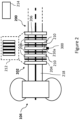
- Figure 2 is a simplified schematic view of an aircraft wheel brake 200 associated with the wheel 104 of the aircraft 100.
- the wheel brake 200 applies a braking force to inhibit the rotation of the wheel 104 when applied.
- Each of the wheels of the aircraft 100 may have a wheel brake 200 associated with it.
- the wheel brake 200 comprises a plurality of brake discs 202 including a pressure plate 204, a reaction plate 206, and a number of rotors 208 and stators 210.
- the brake discs 202 include a plurality of rotors and stators, and the wheel brake 200 is therefore a multiple disc brake.
- the wheel brake 200 may not be a multiple-disc brake: there may be only one disc 208, for example, between a pressure plate 204 and a reaction plate 206.
- the brake discs 202 may include up to 9 discs or 11 discs, or any other number which is suitable for a wheel brake of an aircraft.
- the brake discs 202 may collectively be referred to as a heat pack.
- the components of the wheel brake 200 hereafter, for brevity, the wheel brake 200 is referred to simply as the brake 200
- the brake discs 202 may be housed in a wheel brake housing (not shown).
- the term brake is used as if to include such a wheel brake housing.
- wheel brake used in an aircraft landing gear depends on the characteristics of the aircraft in question, such as size, carrying capacity and the like.
- the following may be applied to any wheel brakes suitable for use as aircraft wheel brakes which heat up when applied to reduce aircraft speed, as discussed in the following.
- the rotors rotate with the wheel 104 (the rotors are keyed to the wheel 104), whereas the stators, the pressure plate 204 and the reaction plate 206 do not rotate with the wheel 104 (the stators, the pressure plate 204 and the reaction plate 206 are keyed to a torque tube 218 associated with the wheel 104 which does not rotate with the wheel 104).
- the pressure plate 204 is urged towards the reaction plate 206 so that the brake discs 202 come into contact with one another (as shown in box 212 of Figure 2 ) and friction acts to inhibit the rotational motion of the rotors, thus generating a braking force.
- the brake 200 is applied, some of the kinetic energy of the aircraft 100 is absorbed into the brake discs 202 as heat (by the action of friction). Accordingly, the brake 200 heats up when it is applied to cause the aircraft 100 to slow down.
- Any one or more of the rotors, stators, pressure plate 204 and the reaction plate 206 may be composed of Carbon-Carbon (CC) composites.
- CC Carbon-Carbon
- a brake including brake discs composed of CC composites may be referred to as a carbon brake.
- the brake discs 202 may be composed of a graphite matrix reinforced by carbon fibers.
- the environment of the brake discs 202 may be harsh due to vibration and/or physical shock during application of braking for example.
- the environment of the brake discs 202 may be harsh due to high temperatures reached by the brake discs 202, for example.
- the aircraft 100 comprises a braking system 214 which controls the operation of the brake 200.
- the braking system 214 causes the brake 200 to be applied in response to a braking request (for example when a pilot of the aircraft 100 presses a brake pedal).
- the brake 200 may be hydraulically actuated in which case the braking system 214 includes a hydraulic system (not shown) operationally connected with the brake 200.
- the brake 200 may be electrically actuated in which case the braking system 214 includes an electronic brake actuation system.
- the braking system 214 may be controlled by the computing system 106.
- FIG 3 is a simplified schematic view of a temperature sensing device 300.
- the temperature sensing device 300 is to sense aircraft wheel brake temperature (for example, the temperature of the brake 200).
- the temperature sensing device 300 may be attached to a component of the brake in order to sense the temperature of that component of the brake 200.
- the temperature sensing device 300 may be attached to one of the brake discs 202.
- the temperature sensing device 300 is attached to one of the stators.
- the temperature sensing device 300 is attached to a first stator 210a, as schematically shown.
- the temperature sensing device 300 may be attached to the first stator 210a in a manner that can withstand the high temperatures expected to occur at the first stator 210a.
- the temperature sensing device 300 may be attached to the first stator 210a by means of a ceramic adhesive.
- Ceramic adhesive may be intended to withstand high temperatures, for example in excess of 1000°C.
- the ceramic adhesive may be applied between the first stator 210a and the temperature sensing device 300 and cured such that the temperature sensing device 300 is bonded to the first stator 210a using cured ceramic adhesive material (for example, ceramic epoxy adhesive material).
- the first stator 210a comprises a first formation (for example, one or more grooves).
- the first formation may be formed by cutting, grinding, drilling, or boring the first formation into the material of the first stator 210a.
- a second formation may be formed from the ceramic adhesive to interlock with the first formation.
- the ceramic adhesive with the second formation may be an attachment element for attaching the temperature sensing device 300 to the first stator 210a.
- the second formation is complementary to the first formation.
- the first formation is a groove formed in the first stator 210a and the second formation is a spike which fits into the groove to inhibit movement between the first stator 210a the attachment element along an axial direction and a circumferential direction of the first stator 210a.
- providing the attachment element as described comprises applying uncured ceramic adhesive material to the surface of the first formation to create the second formation.
- the temperature sensing device 300 may be attached to a brake disc in a number of ways.
- other fasteners such as ceramic bolts may be used to attach the temperature sensing device 300.
- a ceramic bolt may be passed through a through hole in the temperature sensing device 300 and engage with a threaded hole in the first stator 210a.
- an appropriately shaped clip for example, a metal clip
- the clip may comprise through holes and may be attached to the first stator 210a using bolts.
- the temperature sensing device 300 comprises a surface acoustic wave (SAW) sensor element 302.
- the temperature sensing device also comprises a sensor antenna 304, which is electrically coupled to the SAW sensor element 302.
- the temperature sensing device 300 may be a passive device in that it does not require electrical power to operate.
- the SAW sensor element 302 works based on SAWs generated in the SAW sensor element 302.
- the SAW sensor element 302 comprises a transducer which converts an input signal (for example, an electrical signal) into a surface acoustic wave that resonates in the SAW sensor element 302.
- the SAW sensor element 302 also, for example, comprises a transducer to convert the SAW into an output signal (for example, an output signal).
- the temperature sensing device 300 may be configured to withstand the harsh environment of the brake discs 202.
- the temperature sensing device may be configured to withstand at least one of: a saw tooth shock profile of 6g at 20ms duration, a saw tooth shock profile of 55g at 30ms duration, a saw tooth shock profile of 70g at 0.4ms duration, a half-sine shock profile of 40g at 30ms duration, a half-sine shock profile of 50g at 0.5ms duration, and vibration of 50g at 2 kHz for a minimum duration of 3 hours.
- Vibrations and/ or shock testing may be performed in accordance with Radio Technical Commission for Aeronautics (RTCA) DO-160G.
- RTCA Radio Technical Commission for Aeronautics
- the SAW sensor element 302 works based on SAWs generated in the SAW sensor element 302.
- the SAW sensor element 302 comprises a transducer which converts an input signal (for example, an electrical signal) into a surface acoustic wave that resonates in the SAW sensor element 302.
- the SAW sensor element 302 also, for example, comprises a transducer to convert the SAW into an output signal (for example, an output signal). Physical properties (such as temperature, for example) of the SAW sensor element may be determined based on the output signal.
- the input signal may be referred to as an interrogation signal. That is because the interrogation signal causes the output signal based on which, for example, temperature can be determined.
- the interrogation signal therefore acts to query the SAW sensor element 302 to provide an output signal.
- the interrogation signal may be wirelessly received by the temperature sensing device 300.
- the output signal may be wirelessly transmitted by the temperature sensing device 300.
- the SAW sensor element 302 comprises one or more interdigital transducers (IDTs).
- the IDTs are for converting between a SAW and, for example, an electrical signal.
- the functioning of an IDT is described further below.
- the SAW sensor element 302 is a one-port SAW sensor.
- the SAW sensor element 302 has one IDT.
- the SAW sensor element 302 may have one IDT and reflectors either side of the IDT to reflect the SAW.
- the one IDT converts an input signal into a SAW and also converts the SAW back into an electrical signal as a response (output) signal.
- the SAW sensor element 302 is a two-port SAW sensor.
- the SAW sensor element 302 comprises two IDTs spaced apart from one another. There is an input IDT which converts an input signal into a SAW. The SAW travels from the input IDT to an output IDT. The output IDT converts the SAW into an output signal.
- IDT converts the SAW into an output signal.
- FIG. 4 illustrates a particular example of the SAW sensor element 302.
- the SAW sensor element 302 is a two-port SAW sensor, and comprises an input IDT 402 and an output IDT 404.
- Each of the input IDT 420 and the output IDT 404 comprises two interlocking comb-shaped arrays of electrodes, deposited on the surface of a piezoelectric substrate 406 to form a periodic structure.
- the electrodes may be metallic electrodes, for example.
- the input IDT 402 comprises a first periodic electrode structure 402a and the output IDT 404 comprises a second periodic electrode structure 404a.
- the input IDT 402 is provided at a first location of the piezoelectric substrate 406 and the output IDT 404 is provided at a second location of the piezoelectric substrate 406 such that there is a space between the input IDT 402 and the output IDT 404.
- a piezoelectric material can generate an electric charge in response to mechanical stress. Furthermore, a piezoelectric material can deform and generate mechanical stress in response to an applied electric field.
- An alternating electrical signal can be applied to the input IDT 402 such that adjacent electrodes have opposite polarities and the polarity of each electrode alternates according to the applied alternating electrical signal.
- Such a signal causes there to be a region of compressive stress next to a region of tensile stress, and each region alternates between compressive and tensile stress.
- This mechanical wave is what is referred to as a surface acoustic wave (SAW), as described above.
- SAWs in the SAW sensor element 302 are generated at the resonant frequency of the SAW sensor element 302.
- the SAW travels from the input IDT 402 to the output IDT 404.
- the alternating regions of compressive and tensile stress caused by the SAW at the output IDT cause there to be alternating electric fields.
- These alternating electric fields generate an electrical signal in the output IDT such that the polarities of adjacent electrodes of the output IDT 404 alternate in the manner described above for the input IDT 402.
- an electrical signal is generated at the output IDT 404 by the reverse of the process which took place at the input IDT 402 to generate the SAW from the input electrical signal.
- the physical properties (such as temperature, for example) of the SAW sensor element may be determined based on the output signal.
- the characteristics of the SAW in the SAW sensor element 302 depend on the physical properties of the SAW sensor element such as temperature. Therefore, by detecting the characteristics of the SAW, the temperature of the SAW sensor element 302 can be determined. For example, the characteristics of the SAW are detected using the output signal generated by the output IDT 404 in response to an interrogation signal received at the input IDT 402.
- Various characteristics of the SAW may be detected. For example, a delay relating to the transmission of the interrogation signal and receipt of the output signal in response from the temperature sensing device 300, a phase shift response of the SAW sensor element 302, and/or a resonant frequency of the SAW sensor element 302 may be detected.
- the frequency of the output signal corresponds to the frequency of the SAW and therefore the resonant frequency of the SAW sensor element 302.
- a desired physical property of the SAW sensor element 302 (such as temperature) may then be determined from the detected characteristic of the SAW sensor element 302.
- a predefined relationship between the detected characteristic (for example, the resonant frequency) of the SAW sensor element 302 and the temperature of the SAW sensor element 302 may be stored in a computer readable memory (for example, in the computing system 106) on the aircraft 100, for example.
- the predefined relationship specifies what the detected characteristic of the SAW sensor element 302 is expected to be at various different temperatures (for example, obtained from calibration and/or testing of the SAW sensor element 302). For example, from a given resonant frequency, the temperature of the SAW sensor element 302 is determined from the predefined relationship.
- the predefined relationship may be stored in the form of a look-up table, rule, correlation equation, graph, etc.
- the predefined relationship may be determined by performing calibration or other test on the SAW sensor element 302. For example, test may be performed to cause the SAW sensor element 302 to resonate at different temperatures and determine the resonant frequencies at those temperature in order to establish the predefined relationship.
- the temperature sensing device 300 is attached to one of the brake discs 202.
- the temperature sensing device is attached to one of the stators 210. Therefore, the temperature of the SAW sensor element 302 corresponds to the temperature of the brake disc to which it is attached.
- the interrogation signal may be wirelessly received by the temperature sensing device 300.
- the temperature sensing device 300 may comprise (as in the example of Figure 3 ) a sensor antenna 304 configured to wirelessly receive the interrogation signal, and supply the interrogation signal to the SAW sensor element 302.
- the sensor antenna 304 receives the interrogation signal in the form of radio waves and converts the radio waves into an electrical signal.
- the SAW sensor element may be configured to, responsive to the interrogation signal, output a signal as a response (the described output signal), the output signal indicative of the resonant frequency of the SAW sensor element 302, to the sensor antenna 304.
- the sensor antenna 304 may be configured to wirelessly transmit the output signal.
- the sensor antenna 304 converts the electrical output signal into radio waves.
- the sensor antenna 304 supplies the interrogation signal to the input IDT 402 of the SAW sensor element 302.
- the interrogation signal as received at the input IDT 402 is an alternating electrical signal which causes the input IDT 402 to generate a SAW as previously described.
- the SAW sensor element 302 provides an output signal (generated by the output IDT 404 as previously described).
- the output signal is supplied from the output IDT 404 to the sensor antenna 304.
- the sensor antenna 304 transmits the output signal.
- the sensor antenna 304 is electrically coupled to the input IDT 402 and the output IDT 404. The origin of the interrogation signal and the components which receive and process the output signal are described later.
- a change in temperature of the SAW sensor element 302 causes a change in the resonant frequency.
- the resonant frequency of the SAW sensor element decreases.
- the frequency of the SAW depends on the spacing between the electrodes of the IDTs. The spacing between adjacent electrodes is referred to as the pitch of the IDT in question.
- the pitch determines the wavelength of the SAW generated by the IDT.
- the pitch is equal to half of the wavelength of the SAW generated by the IDT. Therefore, the desired frequency resonant frequency of the SAW sensor element
- the frequency of the SAW depends on the propagation velocity of the SAW and the wavelength of the SAW according to Equation (1) below.
- Equation (1) f represents the frequency of the SAW, V s represents the propagation velocity of the SAW in the SAW sensor element in question, and ⁇ represents the wavelength of the SAW.
- the frequency of the SAWs generated in the SAW sensor element 302 can be referred to as the resonant frequency of the SAW sensor element. It will be appreciated that, for a given propagation velocity of the SAW in the SAW sensor element 302, the resonant frequency of the SAW sensor element 302 can be configured by selecting an appropriate pitch for the IDTs of the SAW sensor element 302.
- the temperature of the SAW sensor element 302 may be determined by detecting the resonant frequency of the SAW sensor element 302 as indicated by the output signal.
- FIG. 5 schematically illustrates an example of a temperature sensing system 500 for sensing aircraft wheel brake temperature.
- the temperature sensing system 500 comprises the temperature sensing device 300 according to any of the described examples.
- the temperature sensing system 500 also comprises a wireless relay device 502 to deliver the interrogation signal for wirelessly interrogating the SAW sensor element 302.
- the wireless relay device 502 delivers the interrogation signal by wirelessly transmitting the interrogation signal to the temperature sensing device 300.
- the wireless relay device 502 also wirelessly receives the described output signal.
- the wireless relay device 502 is hereafter simply referred to as the relay 502.
- the relay 502 comprises a relay antenna 504.
- the relay antenna wirelessly transmits the interrogation signal and wirelessly receives the output signal.
- the relay 502 is simply a device for communicating wirelessly with the temperature sensing device 300.
- the temperature sensing device 300 may be attached to one of the brake discs 202.
- the relay 502 may be attached to a component of the brake 200 or wheel 104 such that it can wirelessly communicate with the temperature sensing device 300 attached to a brake disc.
- the relay 502 may be mounted so as to maintain line of sight with the temperature sensing device 300.
- the wireless communication between the temperature sensing device 300 and the relay 502 can be implemented, for example, by electromagnetic, inductive or capacitive coupling of the relay 502 to the temperature sensing device 300.
- each of the sensor antenna 304 and the relay antenna 504 may be configured to convert electrical signals to radio waves and vice versa, with the radio waves being transmitted between the respective antennas.
- the temperature sensing device 300 is attached to the first stator 210a and the relay 502 is attached to the torque tube 218 to which the first stator 210a is keyed.
- the relay 502 is attached to the torque tube at a position so as to be in the line of sight of the temperature sensing device 300 on the first stator 210a.
- the temperature sensing device 300 may be attached to a different brake disc or a different component of the brake 200, and the relay 502 may be attached to an appropriate location to maintain line of sight with the temperature sensing device 300.
- the temperature sensing system 500 may comprise an interrogation apparatus 506.
- the interrogation apparatus 506 may form part of the computing system 106 of the aircraft 100. In such examples, the interrogation apparatus 506 forms a communication link (which may be wireless or wired) with the relay 502.
- the interrogation apparatus 506 comprises a controller 508 configured to provide the interrogation signal.
- the controller 508 may provide the interrogation signal based on a command signal received from another component of the computing system 106.
- the command signal may comprise the interrogation signal, and the interrogation signal may simply be retransmitted towards to the relay 502.
- the command signal may be an instruction for the controller 508 to generate the interrogation signal.
- the interrogation apparatus 506 comprises a transceiver 510 for transmitting the interrogation signal to the relay 502 and receiving the described output signal from the relay 502.
- the transceiver 510 may communicate with the relay 502 via a wired communication link or wirelessly.
- respective antennas may be provided as part of the relay 502 and the interrogation apparatus 506.
- the SAW sensor element 302 has a resonant frequency within a frequency range between 175 megahertz (MHz) and 190MHz at a predetermined temperature.
- a frequency range between 175MHz and 190MHz is not limited to a range having 175MHz as a lower limit and 190MHz as an upper limit.
- the frequency range may be any range that falls between 175 MHz and 190 MHz (for example, 175 MHz to 180 MHz, 176 MHz to 188 MHz, 180 MHz to 190 MHz, etc.).
- the resonant frequency of the SAW sensor element 302 is within the frequency range when the temperature of the SAW sensor element 302 is within a predetermined temperature range (for example, 24°C to 1000°C).
- FIG. 6 is a simplified schematic side cross-sectional view of a first temperature sensing device 600, according to an example.
- the fist temperature sensing device 600 is a more specific example of the described temperature sensing device 300.
- the first temperature sensing device 600 comprises a sensing device substrate 602, and one or more package layers attached to the sensing device substrate 602.
- the sensing device substrate carries one or more electronic components for sensing temperature.
- the electronic components comprise the described SAW sensor element 302 mounted to the sensing device substrate 602.
- the electronic components may also comprise the sensor antenna 304, electrically coupled to the SAW sensor element, provided on the sensing device substrate 602.
- the SAW sensor element 302 is mounted to the sensing device substrate 602.
- the SAW sensor element 302 may be adhered to a surface of the sensing device substrate 602.
- the sensing device substrate 602 comprises a slot into which the SAW sensor element 302 can be mounted.
- the sensor antenna 304 is provided on the first surface 608 of the sensing device substrate 602.
- the one or more package layers comprise a first package layer 610.
- the first temperature sensing device 600 comprises the first package layer 610.
- the first package layer 610 is overlaid on the first surface 608 of the sensing device substrate 602 to cover the sensor antenna 304 and the SAW sensor element 302.
- the first package layer 610 covering the electronic components serves to protect those electronic components.
- the first package layer 610 may protect the electronic components from damage from debris and the like.
- the first temperature sensing device 600 is for sensing aircraft wheel brake temperature and may be attached to the first stator 210a, as described. Therefore, the first temperature sensing device 600 may be in a harsh environment and providing protection for electronic components therein may be advantageous.
- the first temperature sensing device 600 is for use in high temperature environments.
- the first stator 210a may reach temperatures in excess of 700°C.
- the first package layer 610 overlaid to cover the electronic components i.e., the SAW sensor element 302 and the sensor antenna 304) advantageously provides the electronic component with protection from high temperatures.
- the first package layer 610 may act as a temperature shield for the electronic components.
- the sensing device substrate and/or the one or more package layers may comprise a ceramic material.
- the sensing device substrate 602 comprises a ceramic material.
- the sensing device substrate 602 is a layer of ceramic material.
- the ceramic material may be any ceramic material suitable to carry electronic components such as the SAW sensor element 302 and the sensor antenna 304, and suitable to withstand temperature extremes expected to occur at the brake discs 202 of the aircraft 100.
- the first package layer 610 may also comprise the same or different ceramic material to the sensing device substrate 602.
- a layer of a ceramic material may provide good thermal protection for the electronic components carried by the sensing device substrate 602. Therefore, the first package layer 610 comprising a ceramic material advantageously enhances the thermal protection provided to the electronic components carried by the sensing device substrate 602.
- the first package layer 610 comprises one or more slots (not shown) to accommodate the electronic components carried by the sensing device substrate 602.
- the first package layer 610 may comprise one slot provided on the surface which contacts the first surface 608 of the sensing device substrate 602.
- the one slot may provide a space to accommodate the electronic components (such as the SAW sensor element 302 and the sensor antenna 304) so that the first package layer 610 does not physically contact the electronic components.
- the first package layer 610 may contact the first surface 608 close to the outer edges of the first surface 608.
- the first package layer 610 comprises more than one slot.
- the first package layer 610 comprises two slots. There is provided one slot to accommodate the SAW sensor element 302 and another slot to accommodate the sensor antenna 304.
- the first package layer 610 does not comprise any slot as described.
- the first package layer 610 without any slots may be attached to the sensing device substrate in a manner so that it does not physically contact the electronic components.
- the first package layer 610 may be attached to the sensing device substrate 602 using a sealant or the like in a manner that does not adversely contact the electronic components.
- the sensing device substrate 602 and the one or more package layers are hermetically sealed together.
- a hermetic seal may prevent passage of gasses or moisture into the space where the electronic components are.
- the first package layer 610 may be hermetically sealed to the sensing device substrate 602.
- a hermetic seal may advantageously better protect the electronic components (for example, from extreme temperatures) by inhibiting contact with the outside environment.
- the one or more package layers also comprise a second package layer.
- Figure 7 is a simplified schematic cross-sectional view of a second temperature sensing device 700, according to an example.
- the second temperature sensing device 700 is similar to the first temperature sensing device 600. In addition to the previously described features, the second temperature sensing device 700 more than one package layer.
- the second temperature sensing device 700 comprises a second package layer 702 overlaid on the first package layer 610 such that the first package layer 610 is between the sensing device substrate 602 and the second package layer 702.
- the first package layer 610, the second package layer 702 and the sensing device substrate are hermetically sealed to one another. In some examples, the first package layer 610 is hermetically sealed to the sensing device substrate 602, but the second package layer 702 is not hermetically sealed. In some examples, there is no hermetic seal.
- Providing the second package layer 702 may provide better thermal protection for the electronic components compared to omitting it, for example. Also, advantageously, providing the second package layer 702 may provide additional rigidity to the second temperature sensing device 700. The additional rigidity may enhance the physical robustness of the second temperature sensing device 700, for example, for reliable function in the harsh environment of the brake discs 202.
- the one or more package layers also comprise a third package layer.
- a third package layer 704 is provided.
- the third package layer 704 is overlaid on a second surface 706 of the sensing device substrate 602.
- the second surface 706 is on the opposite side of the sensing device substrate 602 to the first surface 608.
- the inclusion of the third package layer 704 may provide additional rigidity to the second temperature sensing device 700 such that it is physically robust, for example, for the harsh environment of the brake discs 202.
- the inclusion of the third package layer 704 may provide additional thermal protection for the electronic components carried by the sensing device substrate 602.
- the inclusion of the second and/or the third package layer may facilitate attachment of the second temperature sensing device 700 via the second and/or the third package layer in a manner that does not affect with the electronic components.
- the one or more package layers may comprise Alumina.
- the one or more package layers may comprise a ceramic material which is suitable for high temperature applications, for example, suitable to withstand temperature up to 1000°C.
- FIG 8 is a flow diagram illustrating a method 800 of manufacturing a temperature sensing device to sense aircraft wheel brake temperature.
- a sensing device substrate (such as the described sensing device substrate 602) carrying one or more electronic components for sensing temperature is provided.
- providing the sensing device substrate 602 may comprise providing the SAW sensor element 302 mounted to the sensing device substrate 602, and providing the sensor antenna 304, electrically coupled to the SAW sensor element 302, on the sensing device substrate 602.
- one or more package layers are attached to the sensing device substrate 602.
- block 804 may involve overlaying the first package layer 610 on the first surface 608 of the sensing device substrate 602 to cover the sensor antenna 304 and the SAW sensor element 302.
- block 804 may involve overlaying the second package layer 702 on the first package layer 610 such that the first package layer 610 is between the sensing device substrate 602 and the second package layer 702. In some examples, block 804 may involve overlaying the third package layer 704 on the second surface 706 of the sensing device substrate 602, wherein the second surface 706 is on the opposite side of the sensing device substrate 602 to the first surface 608. In some examples, block 804 involves hermetically sealing the sensing device substrate and one or more package layers together.
- Attaching layers to one another may involve attachment using adhesive and the like.
- an appropriate sealed may be used and cured to attach one layer to another.
- the layers comprise ceramic material, for example.
- a hermetic seal is formed between the sensing device substrate 602 and the first package layer 610 only.
- the second and/or the third package layers may also form hermetic seals to the layer to which they attach.
- the relay 502 comprises the features relating to the one or more package layers according to any of the described examples in relation to the temperature sensing device.
- the relay 502 comprises a relay substrate, and one or more package layers attached to the relay substrate.
- the one or more package layers may be ceramic layers, for example.
- the relay substrate carries one or more electronic components of the relay 502.
- the one or more package layers of the relay 502 may comprise a ceramic material and provide thermal protection to the electronic components of the relay.
- components are described as being electrically coupled to other components.
- components may be electrically coupled by virtue of an electrical connection.
- electronic components may also be capacitively or inductively coupled, for example. The type of electrical coupling depends on the characteristics of the electronic components and the particular application.
Landscapes
- Physics & Mathematics (AREA)
- Engineering & Computer Science (AREA)
- General Physics & Mathematics (AREA)
- General Engineering & Computer Science (AREA)
- Mechanical Engineering (AREA)
- Acoustics & Sound (AREA)
- Aviation & Aerospace Engineering (AREA)
- Transportation (AREA)
- Arrangements For Transmission Of Measured Signals (AREA)
- Measuring Temperature Or Quantity Of Heat (AREA)
Abstract
Description
- The present invention relates to sensing aircraft wheel brake temperature. More specifically, the present invention relates to a temperature sensing device.
- When aircraft wheel brakes are applied to reduce the speed of an aircraft, the temperature of the aircraft wheel brakes rises. It can be advantageous to monitor the temperature of the aircraft wheel brakes to, for example, ensure that the brakes do not overheat. For example, temperature sensors such as thermocouples can be used to sense temperature.
- A first aspect of the present invention provides a temperature sensing device to sense aircraft wheel brake temperature, the temperature sensing device comprising: a sensing device substrate; and one or more package layers attached to the sensing device substrate, wherein: the sensing device substrate carries one or more electronic components for sensing temperature.
- Optionally, the electronic components comprise: a surface acoustic wave, SAW, sensor element mounted to the sensing device substrate; and a sensor antenna, electrically coupled to the SAW sensor element, provided on the sensing device substrate.
- Optionally, the one or more package layers comprise a first package layer overlaid on a first surface of the sensing device substrate to cover the sensor antenna and the SAW sensor element.
- Optionally, the one or more package layers comprise a second package layer overlaid on the first package layer such that the first package layer is between the sensing device substrate and the second package layer.
- Optionally, the one or more package layers comprise a third package layer overlaid on a second surface of the sensing device substrate, the second surface on the opposite side of the sensing device substrate to the first surface.
- Optionally, the first package layer comprises one or more slots to accommodate the electronic components carried by the sensing device substrate.
- Optionally, the sensing device substrate and the one or more package layers are hermetically sealed together.
- Optionally, the sensing device substrate and/or the one or more package layers comprise a ceramic material.
- According to a second aspect of the present invention, there is provided a method of manufacturing a temperature sensing device to sense aircraft wheel brake temperature, the method comprising: providing a sensing device substrate carrying one or more electronic components for sensing temperature; and attaching one or more package layers to the sensing device substrate.
- Optionally, in the method according to the second aspect, providing the sensing device substrate comprises providing: a surface acoustic wave, SAW, sensor element mounted to the sensing device substrate; and a sensor antenna, electrically coupled to the SAW sensor element, on the sensing device substrate.
- Optionally, in the method according to the second aspect, attaching one or more package layers comprises: overlaying a first package layer on a first surface of the sensing device substrate to cover the sensor antenna and the SAW sensor element.
- Optionally, in the method according to the second aspect, attaching one or more package layers comprises: overlaying a second package layer on the first package layer such that the first package layer is between the sensing device substrate and the second package layer.
- Optionally, in the method according to the second aspect, attaching one or more package layers comprises: overlaying a third package layer on a second surface of the sensing device substrate, the second surface on the opposite side of the sensing device substrate to the first surface.
- Optionally, in the method according to the second aspect, attaching one or package layers comprises: hermetically sealing the sensing device substrate and one or more package layers together.
- According to a third aspect of the present invention, there is provided a wireless relay device to wirelessly transmit an interrogation signal to a temperature sensing device and wirelessly receive an output signal from the temperature sensing device, the temperature sensing device to sense aircraft wheel brake temperature, the wireless relay device comprising: a relay substrate; and one or more ceramic package layers attached to the relay substrate, wherein: the relay substrate carries one or more electronic components of the wireless relay device.
- Embodiments of the invention will now be described, by way of example only, with reference to the accompanying drawings, in which:
-
Figure 1 is a simplified schematic view of an aircraft on which examples may be deployed; -
Figure 2 is a simplified schematic view of a brake and a wheel of an aircraft landing gear assembly according to an example; -
Figure 3 is a simplified schematic block diagram of a temperature sensing device according to a first example; -
Figure 4 is a simplified schematic plan view of a surface acoustic wave sensor element, according to an example; -
Figure 5 is a simplified schematic block diagram of a temperature sensing system according to an example; -
Figure 6 is a simplified schematic side-cross sectional view of a temperature sensing device according to a first example; -
Figure 7 is a simplified schematic side-cross sectional view of a temperature sensing device according to a second example; and -
Figure 8 is a flow diagram of a method of manufacturing a temperature sensing device, according to an example. - The following disclosure relates to a temperature sensing device for sensing aircraft wheel brake temperature.
-
Figure 1 is a simplified schematic view of anaircraft 100. Theaircraft 100 comprises a plurality oflanding gear assemblies 102. The landing gear assemblies may include main and nose landing gears that are deployed or extended during take-off and landing. Eachlanding gear assembly 102 includeswheels 104. Theaircraft 100 comprises acomputing system 106, which, for example, comprises one or more processors and one or more computer readable storage media. Theaircraft 100 may also compriseinstruments 108, such as instruments or sensors for measuring characteristics or parameters related to the aircraft, and instruments or sensors for measuring environmental characteristics. -
Figure 2 is a simplified schematic view of anaircraft wheel brake 200 associated with thewheel 104 of theaircraft 100. Thewheel brake 200 applies a braking force to inhibit the rotation of thewheel 104 when applied. Each of the wheels of theaircraft 100 may have awheel brake 200 associated with it. In this example, thewheel brake 200 comprises a plurality ofbrake discs 202 including apressure plate 204, areaction plate 206, and a number ofrotors 208 andstators 210. In this example, thebrake discs 202 include a plurality of rotors and stators, and thewheel brake 200 is therefore a multiple disc brake. In other examples, thewheel brake 200 may not be a multiple-disc brake: there may be only onedisc 208, for example, between apressure plate 204 and areaction plate 206. In some examples, thebrake discs 202 may include up to 9 discs or 11 discs, or any other number which is suitable for a wheel brake of an aircraft. Thebrake discs 202 may collectively be referred to as a heat pack. The components of the wheel brake 200 (hereafter, for brevity, thewheel brake 200 is referred to simply as the brake 200) such as thebrake discs 202 may be housed in a wheel brake housing (not shown). As referred to herein, the term brake is used as if to include such a wheel brake housing. - It will be understood that the type of wheel brake used in an aircraft landing gear depends on the characteristics of the aircraft in question, such as size, carrying capacity and the like. The following may be applied to any wheel brakes suitable for use as aircraft wheel brakes which heat up when applied to reduce aircraft speed, as discussed in the following.
- When the
aircraft 100 travels along the ground supported by thelanding gear assembly 102, the rotors rotate with the wheel 104 (the rotors are keyed to the wheel 104), whereas the stators, thepressure plate 204 and thereaction plate 206 do not rotate with the wheel 104 (the stators, thepressure plate 204 and thereaction plate 206 are keyed to atorque tube 218 associated with thewheel 104 which does not rotate with the wheel 104). When braking is applied, thepressure plate 204 is urged towards thereaction plate 206 so that thebrake discs 202 come into contact with one another (as shown inbox 212 ofFigure 2 ) and friction acts to inhibit the rotational motion of the rotors, thus generating a braking force. When thebrake 200 is applied, some of the kinetic energy of theaircraft 100 is absorbed into thebrake discs 202 as heat (by the action of friction). Accordingly, thebrake 200 heats up when it is applied to cause theaircraft 100 to slow down. - Any one or more of the rotors, stators,
pressure plate 204 and thereaction plate 206 may be composed of Carbon-Carbon (CC) composites. A brake including brake discs composed of CC composites may be referred to as a carbon brake. For example, thebrake discs 202 may be composed of a graphite matrix reinforced by carbon fibers. - Those skilled in the art will appreciate that the environment of the
brake discs 202 may be harsh due to vibration and/or physical shock during application of braking for example. The environment of thebrake discs 202 may be harsh due to high temperatures reached by thebrake discs 202, for example. - In this example, the
aircraft 100 comprises abraking system 214 which controls the operation of thebrake 200. Thebraking system 214 causes thebrake 200 to be applied in response to a braking request (for example when a pilot of theaircraft 100 presses a brake pedal). For example, thebrake 200 may be hydraulically actuated in which case thebraking system 214 includes a hydraulic system (not shown) operationally connected with thebrake 200. In other examples, thebrake 200 may be electrically actuated in which case thebraking system 214 includes an electronic brake actuation system. Thebraking system 214 may be controlled by thecomputing system 106. -
Figure 3 is a simplified schematic view of atemperature sensing device 300. Thetemperature sensing device 300 is to sense aircraft wheel brake temperature (for example, the temperature of the brake 200). For example, thetemperature sensing device 300 may be attached to a component of the brake in order to sense the temperature of that component of thebrake 200. For example, thetemperature sensing device 300 may be attached to one of thebrake discs 202. In the example ofFigure 2 , thetemperature sensing device 300 is attached to one of the stators. For example, thetemperature sensing device 300 is attached to afirst stator 210a, as schematically shown. - The
temperature sensing device 300 may be attached to thefirst stator 210a in a manner that can withstand the high temperatures expected to occur at thefirst stator 210a. For example, thetemperature sensing device 300 may be attached to thefirst stator 210a by means of a ceramic adhesive. Ceramic adhesive may be intended to withstand high temperatures, for example in excess of 1000°C. For example, the ceramic adhesive may be applied between thefirst stator 210a and thetemperature sensing device 300 and cured such that thetemperature sensing device 300 is bonded to thefirst stator 210a using cured ceramic adhesive material (for example, ceramic epoxy adhesive material). In some examples, thefirst stator 210a comprises a first formation (for example, one or more grooves). The first formation may be formed by cutting, grinding, drilling, or boring the first formation into the material of thefirst stator 210a. In such examples, a second formation may be formed from the ceramic adhesive to interlock with the first formation. For example, the ceramic adhesive with the second formation may be an attachment element for attaching thetemperature sensing device 300 to thefirst stator 210a. For example, the second formation is complementary to the first formation. For example, the first formation is a groove formed in thefirst stator 210a and the second formation is a spike which fits into the groove to inhibit movement between thefirst stator 210a the attachment element along an axial direction and a circumferential direction of thefirst stator 210a. In some examples, providing the attachment element as described comprises applying uncured ceramic adhesive material to the surface of the first formation to create the second formation. - It will be appreciated that the
temperature sensing device 300 may be attached to a brake disc in a number of ways. Alternatively, or in addition to the use of ceramic adhesive, other fasteners such as ceramic bolts may be used to attach thetemperature sensing device 300. For example, a ceramic bolt may be passed through a through hole in thetemperature sensing device 300 and engage with a threaded hole in thefirst stator 210a. In some examples, an appropriately shaped clip (for example, a metal clip) may be used as an attachment element. For example, the clip may comprise through holes and may be attached to thefirst stator 210a using bolts. Those skilled in the art will appreciate the various ways of attaching components to withstand high temperatures. - The
temperature sensing device 300 comprises a surface acoustic wave (SAW)sensor element 302. In the example ofFigure 3 , the temperature sensing device also comprises asensor antenna 304, which is electrically coupled to theSAW sensor element 302. Thetemperature sensing device 300 may be a passive device in that it does not require electrical power to operate. It will be understood that theSAW sensor element 302 works based on SAWs generated in theSAW sensor element 302. For example, theSAW sensor element 302 comprises a transducer which converts an input signal (for example, an electrical signal) into a surface acoustic wave that resonates in theSAW sensor element 302. TheSAW sensor element 302 also, for example, comprises a transducer to convert the SAW into an output signal (for example, an output signal). - The
temperature sensing device 300 may be configured to withstand the harsh environment of thebrake discs 202. For example, the temperature sensing device may be configured to withstand at least one of: a saw tooth shock profile of 6g at 20ms duration, a saw tooth shock profile of 55g at 30ms duration, a saw tooth shock profile of 70g at 0.4ms duration, a half-sine shock profile of 40g at 30ms duration, a half-sine shock profile of 50g at 0.5ms duration, and vibration of 50g at 2 kHz for a minimum duration of 3 hours. Vibrations and/ or shock testing may be performed in accordance with Radio Technical Commission for Aeronautics (RTCA) DO-160G. - It will be understood that the
SAW sensor element 302 works based on SAWs generated in theSAW sensor element 302. For example, theSAW sensor element 302 comprises a transducer which converts an input signal (for example, an electrical signal) into a surface acoustic wave that resonates in theSAW sensor element 302. TheSAW sensor element 302 also, for example, comprises a transducer to convert the SAW into an output signal (for example, an output signal). Physical properties (such as temperature, for example) of the SAW sensor element may be determined based on the output signal. - The input signal may be referred to as an interrogation signal. That is because the interrogation signal causes the output signal based on which, for example, temperature can be determined. The interrogation signal therefore acts to query the
SAW sensor element 302 to provide an output signal. The interrogation signal may be wirelessly received by thetemperature sensing device 300. The output signal may be wirelessly transmitted by thetemperature sensing device 300. - The
SAW sensor element 302 comprises one or more interdigital transducers (IDTs). The IDTs are for converting between a SAW and, for example, an electrical signal. The functioning of an IDT is described further below. In some examples, theSAW sensor element 302 is a one-port SAW sensor. In such examples, theSAW sensor element 302 has one IDT. For example, theSAW sensor element 302 may have one IDT and reflectors either side of the IDT to reflect the SAW. In such examples, the one IDT converts an input signal into a SAW and also converts the SAW back into an electrical signal as a response (output) signal. - In some examples, the
SAW sensor element 302 is a two-port SAW sensor. In such examples, theSAW sensor element 302 comprises two IDTs spaced apart from one another. There is an input IDT which converts an input signal into a SAW. The SAW travels from the input IDT to an output IDT. The output IDT converts the SAW into an output signal. Those skilled in the art will appreciate the various configurations of a SAW sensor element. -
Figure 4 illustrates a particular example of theSAW sensor element 302. In this example, theSAW sensor element 302 is a two-port SAW sensor, and comprises aninput IDT 402 and anoutput IDT 404. Each of the input IDT 420 and theoutput IDT 404 comprises two interlocking comb-shaped arrays of electrodes, deposited on the surface of apiezoelectric substrate 406 to form a periodic structure. The electrodes may be metallic electrodes, for example. In this example, theinput IDT 402 comprises a firstperiodic electrode structure 402a and theoutput IDT 404 comprises a secondperiodic electrode structure 404a. Theinput IDT 402 is provided at a first location of thepiezoelectric substrate 406 and theoutput IDT 404 is provided at a second location of thepiezoelectric substrate 406 such that there is a space between theinput IDT 402 and theoutput IDT 404. - Those skilled in the art will appreciate that a piezoelectric material can generate an electric charge in response to mechanical stress. Furthermore, a piezoelectric material can deform and generate mechanical stress in response to an applied electric field. An alternating electrical signal can be applied to the
input IDT 402 such that adjacent electrodes have opposite polarities and the polarity of each electrode alternates according to the applied alternating electrical signal. Such a signal causes there to be a region of compressive stress next to a region of tensile stress, and each region alternates between compressive and tensile stress. As a result of this alternating compressive and tensile stress, there is generated a mechanical wave. This mechanical wave is what is referred to as a surface acoustic wave (SAW), as described above. SAWs in theSAW sensor element 302 are generated at the resonant frequency of theSAW sensor element 302. - In the example of
Figure 4 , the SAW travels from theinput IDT 402 to theoutput IDT 404. The alternating regions of compressive and tensile stress caused by the SAW at the output IDT cause there to be alternating electric fields. These alternating electric fields generate an electrical signal in the output IDT such that the polarities of adjacent electrodes of theoutput IDT 404 alternate in the manner described above for theinput IDT 402. In other words, an electrical signal is generated at theoutput IDT 404 by the reverse of the process which took place at theinput IDT 402 to generate the SAW from the input electrical signal. - As previously described, the physical properties (such as temperature, for example) of the SAW sensor element may be determined based on the output signal. The characteristics of the SAW in the
SAW sensor element 302 depend on the physical properties of the SAW sensor element such as temperature. Therefore, by detecting the characteristics of the SAW, the temperature of theSAW sensor element 302 can be determined. For example, the characteristics of the SAW are detected using the output signal generated by theoutput IDT 404 in response to an interrogation signal received at theinput IDT 402. - Various characteristics of the SAW may be detected. For example, a delay relating to the transmission of the interrogation signal and receipt of the output signal in response from the
temperature sensing device 300, a phase shift response of theSAW sensor element 302, and/or a resonant frequency of theSAW sensor element 302 may be detected. For example, the frequency of the output signal corresponds to the frequency of the SAW and therefore the resonant frequency of theSAW sensor element 302. A desired physical property of the SAW sensor element 302 (such as temperature) may then be determined from the detected characteristic of theSAW sensor element 302. - A predefined relationship between the detected characteristic (for example, the resonant frequency) of the
SAW sensor element 302 and the temperature of theSAW sensor element 302 may be stored in a computer readable memory (for example, in the computing system 106) on theaircraft 100, for example. The predefined relationship specifies what the detected characteristic of theSAW sensor element 302 is expected to be at various different temperatures (for example, obtained from calibration and/or testing of the SAW sensor element 302). For example, from a given resonant frequency, the temperature of theSAW sensor element 302 is determined from the predefined relationship. The predefined relationship may be stored in the form of a look-up table, rule, correlation equation, graph, etc. - The predefined relationship may be determined by performing calibration or other test on the
SAW sensor element 302. For example, test may be performed to cause theSAW sensor element 302 to resonate at different temperatures and determine the resonant frequencies at those temperature in order to establish the predefined relationship. - As previously described, the
temperature sensing device 300 is attached to one of thebrake discs 202. In the example ofFigure 2 , the temperature sensing device is attached to one of thestators 210. Therefore, the temperature of theSAW sensor element 302 corresponds to the temperature of the brake disc to which it is attached. - The interrogation signal may be wirelessly received by the
temperature sensing device 300. Thetemperature sensing device 300 may comprise (as in the example ofFigure 3 ) asensor antenna 304 configured to wirelessly receive the interrogation signal, and supply the interrogation signal to theSAW sensor element 302. For example, thesensor antenna 304 receives the interrogation signal in the form of radio waves and converts the radio waves into an electrical signal. The SAW sensor element may be configured to, responsive to the interrogation signal, output a signal as a response (the described output signal), the output signal indicative of the resonant frequency of theSAW sensor element 302, to thesensor antenna 304. For example, thesensor antenna 304 may be configured to wirelessly transmit the output signal. For example, thesensor antenna 304 converts the electrical output signal into radio waves. - For example, the
sensor antenna 304 supplies the interrogation signal to theinput IDT 402 of theSAW sensor element 302. The interrogation signal as received at theinput IDT 402 is an alternating electrical signal which causes theinput IDT 402 to generate a SAW as previously described. TheSAW sensor element 302 provides an output signal (generated by theoutput IDT 404 as previously described). For example, the output signal is supplied from theoutput IDT 404 to thesensor antenna 304. Thesensor antenna 304 transmits the output signal. For example, thesensor antenna 304 is electrically coupled to theinput IDT 402 and theoutput IDT 404. The origin of the interrogation signal and the components which receive and process the output signal are described later. - A change in temperature of the
SAW sensor element 302 causes a change in the resonant frequency. For example, as the temperature of theSAW sensor element 302 increases, the resonant frequency of the SAW sensor element decreases. The frequency of the SAW depends on the spacing between the electrodes of the IDTs. The spacing between adjacent electrodes is referred to as the pitch of the IDT in question. The pitch determines the wavelength of the SAW generated by the IDT. The pitch is equal to half of the wavelength of the SAW generated by the IDT. Therefore, the desired frequency resonant frequency of the SAW sensor element - The frequency of the SAW depends on the propagation velocity of the SAW and the wavelength of the SAW according to Equation (1) below.

- In Equation (1), f represents the frequency of the SAW, Vs represents the propagation velocity of the SAW in the SAW sensor element in question, and λ represents the wavelength of the SAW.
- The frequency of the SAWs generated in the
SAW sensor element 302 can be referred to as the resonant frequency of the SAW sensor element. It will be appreciated that, for a given propagation velocity of the SAW in theSAW sensor element 302, the resonant frequency of theSAW sensor element 302 can be configured by selecting an appropriate pitch for the IDTs of theSAW sensor element 302. - The temperature of the
SAW sensor element 302 may be determined by detecting the resonant frequency of theSAW sensor element 302 as indicated by the output signal. -
Figure 5 schematically illustrates an example of atemperature sensing system 500 for sensing aircraft wheel brake temperature. Thetemperature sensing system 500 comprises thetemperature sensing device 300 according to any of the described examples. Thetemperature sensing system 500 also comprises awireless relay device 502 to deliver the interrogation signal for wirelessly interrogating theSAW sensor element 302. Thewireless relay device 502 delivers the interrogation signal by wirelessly transmitting the interrogation signal to thetemperature sensing device 300. Thewireless relay device 502 also wirelessly receives the described output signal. Thewireless relay device 502 is hereafter simply referred to as therelay 502. - In some examples, the
relay 502 comprises arelay antenna 504. The relay antenna wirelessly transmits the interrogation signal and wirelessly receives the output signal. In some such examples, therelay 502 is simply a device for communicating wirelessly with thetemperature sensing device 300. As described, thetemperature sensing device 300 may be attached to one of thebrake discs 202. Therelay 502 may be attached to a component of thebrake 200 orwheel 104 such that it can wirelessly communicate with thetemperature sensing device 300 attached to a brake disc. For example, therelay 502 may be mounted so as to maintain line of sight with thetemperature sensing device 300. - The wireless communication between the
temperature sensing device 300 and therelay 502 can be implemented, for example, by electromagnetic, inductive or capacitive coupling of therelay 502 to thetemperature sensing device 300. For example, each of thesensor antenna 304 and therelay antenna 504 may be configured to convert electrical signals to radio waves and vice versa, with the radio waves being transmitted between the respective antennas. - In some examples, the
temperature sensing device 300 is attached to thefirst stator 210a and therelay 502 is attached to thetorque tube 218 to which thefirst stator 210a is keyed. In such examples, therelay 502 is attached to the torque tube at a position so as to be in the line of sight of thetemperature sensing device 300 on thefirst stator 210a. In other examples, thetemperature sensing device 300 may be attached to a different brake disc or a different component of thebrake 200, and therelay 502 may be attached to an appropriate location to maintain line of sight with thetemperature sensing device 300. - The
temperature sensing system 500 may comprise aninterrogation apparatus 506. Theinterrogation apparatus 506 may form part of thecomputing system 106 of theaircraft 100. In such examples, theinterrogation apparatus 506 forms a communication link (which may be wireless or wired) with therelay 502. Theinterrogation apparatus 506 comprises acontroller 508 configured to provide the interrogation signal. For example, thecontroller 508 may provide the interrogation signal based on a command signal received from another component of thecomputing system 106. The command signal may comprise the interrogation signal, and the interrogation signal may simply be retransmitted towards to therelay 502. In other examples, the command signal may be an instruction for thecontroller 508 to generate the interrogation signal. - In the example of
Figure 5 , theinterrogation apparatus 506 comprises atransceiver 510 for transmitting the interrogation signal to therelay 502 and receiving the described output signal from therelay 502. Thetransceiver 510 may communicate with therelay 502 via a wired communication link or wirelessly. For example, for wireless communication, respective antennas may be provided as part of therelay 502 and theinterrogation apparatus 506. - The
SAW sensor element 302 has a resonant frequency within a frequency range between 175 megahertz (MHz) and 190MHz at a predetermined temperature. A frequency range between 175MHz and 190MHz is not limited to a range having 175MHz as a lower limit and 190MHz as an upper limit. For example, the frequency range may be any range that falls between 175 MHz and 190 MHz (for example, 175 MHz to 180 MHz, 176 MHz to 188 MHz, 180 MHz to 190 MHz, etc.). In some examples, the resonant frequency of theSAW sensor element 302 is within the frequency range when the temperature of theSAW sensor element 302 is within a predetermined temperature range (for example, 24°C to 1000°C). -
Figure 6 is a simplified schematic side cross-sectional view of a firsttemperature sensing device 600, according to an example. The fisttemperature sensing device 600 is a more specific example of the describedtemperature sensing device 300. The firsttemperature sensing device 600 comprises asensing device substrate 602, and one or more package layers attached to thesensing device substrate 602. The sensing device substrate carries one or more electronic components for sensing temperature. In some examples, the electronic components comprise the describedSAW sensor element 302 mounted to thesensing device substrate 602. The electronic components may also comprise thesensor antenna 304, electrically coupled to the SAW sensor element, provided on thesensing device substrate 602. - In the example of
Figure 6 , theSAW sensor element 302 is mounted to thesensing device substrate 602. In some examples, theSAW sensor element 302 may be adhered to a surface of thesensing device substrate 602. In some examples, thesensing device substrate 602 comprises a slot into which theSAW sensor element 302 can be mounted. Those skilled in the art will appreciate the various way of mounting an electrical component such as theSAW sensor element 302 to thesensing device substrate 602. - In the example of
Figure 6 , thesensor antenna 304 is provided on thefirst surface 608 of thesensing device substrate 602. In some examples, the one or more package layers comprise afirst package layer 610. In the example ofFigure 6 , the firsttemperature sensing device 600 comprises thefirst package layer 610. In other examples, there may be provided further package layers. Such examples are described later. - The
first package layer 610 is overlaid on thefirst surface 608 of thesensing device substrate 602 to cover thesensor antenna 304 and theSAW sensor element 302. Advantageously, thefirst package layer 610 covering the electronic components serves to protect those electronic components. For example, thefirst package layer 610 may protect the electronic components from damage from debris and the like. It will be appreciated that the firsttemperature sensing device 600 is for sensing aircraft wheel brake temperature and may be attached to thefirst stator 210a, as described. Therefore, the firsttemperature sensing device 600 may be in a harsh environment and providing protection for electronic components therein may be advantageous. - It will also be appreciated that the first
temperature sensing device 600 is for use in high temperature environments. For example, thefirst stator 210a may reach temperatures in excess of 700°C. Thefirst package layer 610 overlaid to cover the electronic components (i.e., theSAW sensor element 302 and the sensor antenna 304) advantageously provides the electronic component with protection from high temperatures. For example, thefirst package layer 610 may act as a temperature shield for the electronic components. - The sensing device substrate and/or the one or more package layers may comprise a ceramic material. In some examples, the
sensing device substrate 602 comprises a ceramic material. For example, thesensing device substrate 602 is a layer of ceramic material. The ceramic material may be any ceramic material suitable to carry electronic components such as theSAW sensor element 302 and thesensor antenna 304, and suitable to withstand temperature extremes expected to occur at thebrake discs 202 of theaircraft 100. - Alternatively, or in addition, the
first package layer 610 may also comprise the same or different ceramic material to thesensing device substrate 602. Advantageously, a layer of a ceramic material may provide good thermal protection for the electronic components carried by thesensing device substrate 602. Therefore, thefirst package layer 610 comprising a ceramic material advantageously enhances the thermal protection provided to the electronic components carried by thesensing device substrate 602. - In some examples, the
first package layer 610 comprises one or more slots (not shown) to accommodate the electronic components carried by thesensing device substrate 602. For example, thefirst package layer 610 may comprise one slot provided on the surface which contacts thefirst surface 608 of thesensing device substrate 602. The one slot may provide a space to accommodate the electronic components (such as theSAW sensor element 302 and the sensor antenna 304) so that thefirst package layer 610 does not physically contact the electronic components. In such examples, thefirst package layer 610 may contact thefirst surface 608 close to the outer edges of thefirst surface 608. - In the example of
Figure 6 , thefirst package layer 610 comprises more than one slot. In the schematic shown inFigure 6 , thefirst package layer 610 comprises two slots. There is provided one slot to accommodate theSAW sensor element 302 and another slot to accommodate thesensor antenna 304. In some examples, thefirst package layer 610 does not comprise any slot as described. For example, thefirst package layer 610 without any slots may be attached to the sensing device substrate in a manner so that it does not physically contact the electronic components. For example, thefirst package layer 610 may be attached to thesensing device substrate 602 using a sealant or the like in a manner that does not adversely contact the electronic components. - In some examples, the
sensing device substrate 602 and the one or more package layers are hermetically sealed together. Those skilled in the art will appreciate that such a hermetic seal may prevent passage of gasses or moisture into the space where the electronic components are. For example, thefirst package layer 610 may be hermetically sealed to thesensing device substrate 602. A hermetic seal may advantageously better protect the electronic components (for example, from extreme temperatures) by inhibiting contact with the outside environment. - In some examples, the one or more package layers also comprise a second package layer.
Figure 7 is a simplified schematic cross-sectional view of a secondtemperature sensing device 700, according to an example. - The second
temperature sensing device 700 is similar to the firsttemperature sensing device 600. In addition to the previously described features, the secondtemperature sensing device 700 more than one package layer. The secondtemperature sensing device 700 comprises asecond package layer 702 overlaid on thefirst package layer 610 such that thefirst package layer 610 is between thesensing device substrate 602 and thesecond package layer 702. - In some examples, the
first package layer 610, thesecond package layer 702 and the sensing device substrate are hermetically sealed to one another. In some examples, thefirst package layer 610 is hermetically sealed to thesensing device substrate 602, but thesecond package layer 702 is not hermetically sealed. In some examples, there is no hermetic seal. - Providing the
second package layer 702 may provide better thermal protection for the electronic components compared to omitting it, for example. Also, advantageously, providing thesecond package layer 702 may provide additional rigidity to the secondtemperature sensing device 700. The additional rigidity may enhance the physical robustness of the secondtemperature sensing device 700, for example, for reliable function in the harsh environment of thebrake discs 202. - In some examples, the one or more package layers also comprise a third package layer. In the example of
Figure 7 , athird package layer 704 is provided. Thethird package layer 704 is overlaid on asecond surface 706 of thesensing device substrate 602. Thesecond surface 706 is on the opposite side of thesensing device substrate 602 to thefirst surface 608. - The inclusion of the
third package layer 704 may provide additional rigidity to the secondtemperature sensing device 700 such that it is physically robust, for example, for the harsh environment of thebrake discs 202. The inclusion of thethird package layer 704 may provide additional thermal protection for the electronic components carried by thesensing device substrate 602. - In some examples, the inclusion of the second and/or the third package layer may facilitate attachment of the second
temperature sensing device 700 via the second and/or the third package layer in a manner that does not affect with the electronic components. - The one or more package layers may comprise Alumina. The one or more package layers may comprise a ceramic material which is suitable for high temperature applications, for example, suitable to withstand temperature up to 1000°C.
-
Figure 8 is a flow diagram illustrating amethod 800 of manufacturing a temperature sensing device to sense aircraft wheel brake temperature. Atblock 802 of themethod 800, a sensing device substrate (such as the described sensing device substrate 602) carrying one or more electronic components for sensing temperature is provided. For example, providing thesensing device substrate 602 may comprise providing theSAW sensor element 302 mounted to thesensing device substrate 602, and providing thesensor antenna 304, electrically coupled to theSAW sensor element 302, on thesensing device substrate 602. - At
block 804 of themethod 800, one or more package layers are attached to thesensing device substrate 602. For example, block 804 may involve overlaying thefirst package layer 610 on thefirst surface 608 of thesensing device substrate 602 to cover thesensor antenna 304 and theSAW sensor element 302. - In some examples, block 804 may involve overlaying the
second package layer 702 on thefirst package layer 610 such that thefirst package layer 610 is between thesensing device substrate 602 and thesecond package layer 702. In some examples, block 804 may involve overlaying thethird package layer 704 on thesecond surface 706 of thesensing device substrate 602, wherein thesecond surface 706 is on the opposite side of thesensing device substrate 602 to thefirst surface 608. In some examples, block 804 involves hermetically sealing the sensing device substrate and one or more package layers together. - Attaching layers to one another may involve attachment using adhesive and the like. In the examples where hermetic seals are formed, an appropriate sealed may be used and cured to attach one layer to another. Those skilled in the art will appreciate the techniques for attaching one layer to another, where the layers comprise ceramic material, for example.
- In some examples, a hermetic seal is formed between the
sensing device substrate 602 and thefirst package layer 610 only. In other examples, the second and/or the third package layers may also form hermetic seals to the layer to which they attach. - In some examples, the
relay 502 comprises the features relating to the one or more package layers according to any of the described examples in relation to the temperature sensing device. For example, therelay 502 comprises a relay substrate, and one or more package layers attached to the relay substrate. The one or more package layers may be ceramic layers, for example. The relay substrate carries one or more electronic components of therelay 502. For example, the one or more package layers of therelay 502 may comprise a ceramic material and provide thermal protection to the electronic components of the relay. - Certain components are described as being electrically coupled to other components. In some examples, components may be electrically coupled by virtue of an electrical connection. Those skilled in the art will appreciate that electronic components may also be capacitively or inductively coupled, for example. The type of electrical coupling depends on the characteristics of the electronic components and the particular application.
- It should be noted that the Figures show simplified schematic views for the purpose of illustration. The Figures are intended to illustrate the described concepts and are not intended to convey dimensions, relative sizes of components and the like. In some cases, certain components are not shown for simplicity, as will be appreciated by those skilled in the art.
- Although the invention has been described above with reference to one or more preferred examples, it will be appreciated that various changes or modifications may be made without departing from the scope of the invention as defined in the appended claims.
Claims (15)
- A temperature sensing device to sense aircraft wheel brake temperature, the temperature sensing device comprising:a sensing device substrate; andone or more package layers attached to the sensing device substrate,wherein:
the sensing device substrate carries one or more electronic components for sensing temperature. - The temperature sensing device according to claim 1, wherein the electronic components comprise:a surface acoustic wave, SAW, sensor element mounted to the sensing device substrate; anda sensor antenna, electrically coupled to the SAW sensor element, provided on the sensing device substrate.
- The temperature sensing device according to claim 1 or claim 2, wherein:
the one or more package layers comprise a first package layer overlaid on a first surface of the sensing device substrate to cover the sensor antenna and the SAW sensor element. - The temperature sensing device according to claim 3, wherein:
the one or more package layers comprise a second package layer overlaid on the first package layer such that the first package layer is between the sensing device substrate and the second package layer. - The temperature sensing device according to claim 3 or claim 4, wherein:
the one or more package layers comprise a third package layer overlaid on a second surface of the sensing device substrate, the second surface on the opposite side of the sensing device substrate to the first surface. - The temperature sensing device according to any one of claims 3 to 5, wherein:
the first package layer comprises one or more slots to accommodate the electronic components carried by the sensing device substrate. - The temperature sensing device according to any one of the preceding claims, wherein:
the sensing device substrate and the one or more package layers are hermetically sealed together. - The temperature sensing device according to any one of the preceding claims, wherein:
the sensing device substrate and/or the one or more package layers comprise a ceramic material. - A method of manufacturing a temperature sensing device to sense aircraft wheel brake temperature, the method comprising:providing a sensing device substrate carrying one or more electronic components for sensing temperature; andattaching one or more package layers to the sensing device substrate.
- The method according to claim 9, wherein providing the sensing device substrate comprises providing:a surface acoustic wave, SAW, sensor element mounted to the sensing device substrate; anda sensor antenna, electrically coupled to the SAW sensor element, on the sensing device substrate.
- The method according to claim 9 or claim 10, wherein attaching one or more package layers comprises:
overlaying a first package layer on a first surface of the sensing device substrate to cover the sensor antenna and the SAW sensor element. - The method according to claim 8, wherein attaching one or more package layers comprises:
overlaying a second package layer on the first package layer such that the first package layer is between the sensing device substrate and the second package layer. - The method according to claim 12, wherein attaching one or more package layers comprises:
overlaying a third package layer on a second surface of the sensing device substrate, the second surface on the opposite side of the sensing device substrate to the first surface. - The method according to any one of claims 8 to 13, wherein attaching one or package layers comprises:
hermetically sealing the sensing device substrate and one or more package layers together. - A wireless relay device to wirelessly transmit an interrogation signal to a temperature sensing device and wirelessly receive an output signal from the temperature sensing device, the temperature sensing device to sense aircraft wheel brake temperature, the wireless relay device comprising:a relay substrate; andone or more ceramic package layers attached to the relay substrate,wherein:
the relay substrate carries one or more electronic components of the wireless relay device.
Applications Claiming Priority (1)
| Application Number | Priority Date | Filing Date | Title |
|---|---|---|---|
| US202163284510P | 2021-11-30 | 2021-11-30 |
Publications (1)
| Publication Number | Publication Date |
|---|---|
| EP4187119A1 true EP4187119A1 (en) | 2023-05-31 |
Family
ID=81581494
Family Applications (1)
| Application Number | Title | Priority Date | Filing Date |
|---|---|---|---|
| EP22210451.5A Withdrawn EP4187119A1 (en) | 2021-11-30 | 2022-11-30 | Temperature sensing device for aircraft wheel brake |
Country Status (4)
| Country | Link |
|---|---|
| US (1) | US12625015B2 (en) |
| EP (1) | EP4187119A1 (en) |
| CN (1) | CN116202647A (en) |
| GB (1) | GB2613414A (en) |
Families Citing this family (2)
| Publication number | Priority date | Publication date | Assignee | Title |
|---|---|---|---|---|
| GB2613409A (en) * | 2021-11-30 | 2023-06-07 | Airbus Operations Ltd | Cable structure for use in aircraft wheel brakes |
| GB2613414A (en) | 2021-11-30 | 2023-06-07 | Airbus Operations Ltd | Temperature sensing device for aircraft wheel brake |
Citations (5)
| Publication number | Priority date | Publication date | Assignee | Title |
|---|---|---|---|---|
| US20020062904A1 (en) * | 2000-11-29 | 2002-05-30 | Samsung Electro-Mechanics Co.,Ltd. | Method and device for sealing ceramic package of saw filter |
| US20070188054A1 (en) * | 2006-02-13 | 2007-08-16 | Honeywell International Inc. | Surface acoustic wave packages and methods of forming same |
| CN107271028A (en) * | 2017-05-26 | 2017-10-20 | 中电科技德清华莹电子有限公司 | A kind of hyperthermal environments passive wireless acoustic surface wave sensor-based system transponder |
| EP3255399A2 (en) * | 2016-05-16 | 2017-12-13 | Airbus Operations Limited | Aircraft brake temperature measurement |
| US20190057887A1 (en) * | 2017-08-17 | 2019-02-21 | Tokyo Electron Limited | Apparatus and method for real-time sensing of properties in industrial manufacturing equipment |
Family Cites Families (125)
| Publication number | Priority date | Publication date | Assignee | Title |
|---|---|---|---|---|
| US3788143A (en) | 1972-03-17 | 1974-01-29 | Westinghouse Electric Corp | Interstage disc cavity removable temperature probe |
| US4249642A (en) * | 1978-11-06 | 1981-02-10 | The Bendix Corporation | Oxidation inhibiting cap for a carbon friction disc |
| US4241603A (en) * | 1979-02-02 | 1980-12-30 | The Bendix Corporation | Aircraft brake thermal sensor |
| US4569600A (en) * | 1983-03-24 | 1986-02-11 | Allied Corporation | Brake temperature sensor |
| US4658936A (en) * | 1985-07-25 | 1987-04-21 | Goodyear Aerospace Corporation | Brake temperature and wear indicator |
| US5345134A (en) * | 1988-06-29 | 1994-09-06 | Raytheon Company | Saw device and method of manufacture |
| DE4006885C2 (en) | 1989-04-05 | 1995-04-13 | Siemens Ag | Evaluation method for a sensor for measuring the temperature of a moving, preferably rotating body, in particular a rotating brake disc |
| GB2250364B (en) | 1990-09-10 | 1994-11-02 | Jeffrey Wallis | Apparatus for use in retail operations |
| FR2672559B1 (en) | 1991-02-12 | 1993-05-28 | Aerospatiale | BRAKING SYSTEM FOR A WHEEL VEHICLE. |
| US6738697B2 (en) * | 1995-06-07 | 2004-05-18 | Automotive Technologies International Inc. | Telematics system for vehicle diagnostics |
| US5651430A (en) * | 1992-03-31 | 1997-07-29 | Rancourt; Claude | Disc brake assembly |
| US5446452A (en) * | 1993-02-05 | 1995-08-29 | Litton; Charles J. | Temperature monitoring system |
| US5392716A (en) | 1993-07-28 | 1995-02-28 | General Electric Company | Locomotive traction motor control system |
| US9008854B2 (en) * | 1995-06-07 | 2015-04-14 | American Vehicular Sciences Llc | Vehicle component control methods and systems |
| US7786864B1 (en) * | 2000-09-08 | 2010-08-31 | Automotive Technologies International, Inc. | Vehicular RFID and sensor assemblies |
| US7313467B2 (en) * | 2000-09-08 | 2007-12-25 | Automotive Technologies International Inc. | System and method for in-vehicle communications |
| JP3289581B2 (en) * | 1995-11-13 | 2002-06-10 | 住友電装株式会社 | Heat-resistant electric wire and method of manufacturing heat-resistant electric wire |
| CA2163702C (en) * | 1995-11-24 | 2000-05-30 | Mark Beauchamp | Flame resistant electric cable |
| US5862890A (en) | 1996-01-16 | 1999-01-26 | Mcdonnell Douglas Corporation | Restrained aircraft brake apparatus |
| JP3741769B2 (en) | 1996-03-06 | 2006-02-01 | カヤバ工業株式会社 | Brake equipment for railway vehicles |
| US5909171A (en) * | 1997-07-17 | 1999-06-01 | Meritor Heavy Vehicle Systems, L L C | Temperature sensing brake lining wear indicator |
| US6620860B2 (en) * | 2000-03-31 | 2003-09-16 | Sumitomo Electric Industries, Ltd. | Friction material |
| US6431824B2 (en) | 1999-10-01 | 2002-08-13 | General Electric Company | Turbine nozzle stage having thermocouple guide tube |
| DE10018513A1 (en) * | 2000-04-14 | 2001-10-18 | Knorr Bremse Systeme | Brake disc monitoring device and monitoring method for monitoring the temperature of brake discs |
| US6571638B2 (en) * | 2000-06-30 | 2003-06-03 | Sawtek, Inc. | Surface-acoustic-wave pressure sensor and associated methods |
| WO2002012043A1 (en) * | 2000-08-04 | 2002-02-14 | Dunlop Aerospace Limited | Brake condition monitoring |
| US6696937B1 (en) * | 2001-05-14 | 2004-02-24 | Karl F. Kiefer | Wireless brake condition monitor |
| DE10133579A1 (en) * | 2001-07-11 | 2003-01-30 | Federal Mogul Friction Product | Disc brake with integrated brake pad |
| US6592253B2 (en) | 2001-10-09 | 2003-07-15 | Northrop Grumman Corporation | Precision temperature probe having fast response |
| DE10215834A1 (en) * | 2002-05-10 | 2003-11-06 | Digades Gmbh | Tire pressure and temperature sensor comprises a hermetically sealed housing with a membrane, piezoelectric support, interdigital transducer and measurement and reference reflectors |
| WO2012125726A1 (en) * | 2011-03-14 | 2012-09-20 | Intelligent Technologies International, Inc. | Cargo theft prevention system and method |
| US20040196888A1 (en) | 2002-10-31 | 2004-10-07 | Fluke Corporation | IR thermometer for automotive applications |
| US6822582B2 (en) * | 2003-02-25 | 2004-11-23 | Hunter Engineering Company | Radio frequency identification automotive service systems |
| JP3913700B2 (en) * | 2003-04-08 | 2007-05-09 | 富士通メディアデバイス株式会社 | Surface acoustic wave device and manufacturing method thereof |
| TW577161B (en) * | 2003-04-17 | 2004-02-21 | Ftech Corp | Package structure having cavity |
| US7100451B2 (en) * | 2003-08-29 | 2006-09-05 | Sawtek, Inc. | Surface acoustic wave sensing system and method for measuring pressure and temperature |
| US7135790B2 (en) * | 2003-10-24 | 2006-11-14 | William Fondriest | Modular electrical harness for jet aircraft landing gear systems |
| JP2005198051A (en) * | 2004-01-08 | 2005-07-21 | Hitachi Ltd | High frequency module |
| US6958565B1 (en) * | 2004-04-05 | 2005-10-25 | Honeywell International Inc. | Passive wireless piezoelectric smart tire sensor with reduced size |
| US7489996B2 (en) * | 2004-05-06 | 2009-02-10 | Hydro-Aire, Inc. | Antiskid control unit and data collection system for vehicle braking system |
| US8742944B2 (en) * | 2004-06-21 | 2014-06-03 | Siemens Energy, Inc. | Apparatus and method of monitoring operating parameters of a gas turbine |
| US7089099B2 (en) * | 2004-07-30 | 2006-08-08 | Automotive Technologies International, Inc. | Sensor assemblies |
| FR2880603B1 (en) * | 2005-01-11 | 2007-03-16 | Messier Bugatti Sa | METHOD FOR MANAGING PARK EFFORT IN A VEHICLE BRAKING SYSTEM EQUIPPED WITH ELECTRIC BRAKES |
| US20060226698A1 (en) * | 2005-04-11 | 2006-10-12 | Gary Riebe | Aircraft taxi speed control system and method |
| US20060238078A1 (en) * | 2005-04-21 | 2006-10-26 | Honeywell International, Inc. | Wireless and passive acoustic wave rotation rate sensor |
| CN101208730A (en) * | 2005-06-29 | 2008-06-25 | 米其林技术公司 | Radio Frequency Identification with Storing SAW Calibration Coefficients |
| US20070114889A1 (en) * | 2005-11-21 | 2007-05-24 | Honeywell International | Chip level packaging for wireless surface acoustic wave sensor |
| US20070139165A1 (en) * | 2005-12-19 | 2007-06-21 | Honeywell International, Inc. | Acoustic wave device used as RFID and as sensor |
| US20070177866A1 (en) * | 2006-01-31 | 2007-08-02 | Yoshizo Fujimoto | Camera extension arm |
| US20080092641A1 (en) * | 2006-10-18 | 2008-04-24 | Goodrich Corporation | Wear compensated torque measurement system |
| US7576470B2 (en) * | 2007-04-30 | 2009-08-18 | Honeywell International Inc. | Mechanical packaging of surface acoustic wave device for sensing applications |
| US8087824B2 (en) * | 2007-07-26 | 2012-01-03 | Honeywell International Inc. | Aircraft brake assembly having a temperature probe and method of mounting a temperature probe in a brake assembly |
| US8483922B2 (en) * | 2007-09-10 | 2013-07-09 | Komatsu Ltd. | Work vehicle and method for controlling work vehicle |
| US8151944B2 (en) * | 2007-11-14 | 2012-04-10 | Goodrich Corporation | Algorithm to determine wheel and brake cooling |
| EP2065681A1 (en) * | 2007-11-30 | 2009-06-03 | Paramata Limited | Sensing system and method |
| US7730772B2 (en) * | 2007-12-28 | 2010-06-08 | Honeywell International Inc. | Surface acoustic wave sensor and package |
| US7726184B2 (en) * | 2007-12-28 | 2010-06-01 | Honeywell International Inc. | Surface acoustic wave sensor and package |
| US8022843B2 (en) * | 2008-03-31 | 2011-09-20 | The Boeing Company | Wireless aircraft sensor network |
| CA2730318C (en) | 2008-07-10 | 2018-05-22 | Nbs Innovative Solutions Ltd. | Vehicle brake monitoring system and method |
| JP2010064816A (en) | 2008-09-09 | 2010-03-25 | Mitsubishi Electric Corp | Passenger conveyer |
| US9796364B2 (en) * | 2009-03-30 | 2017-10-24 | General Electric Company | Apparatus and method for advanced anti-skid brake and traction controls |
| CN101625274B (en) | 2009-08-06 | 2011-01-05 | 浙江大学 | Surface Acoustic Wave Pressure and Temperature Sensors |
| US8348504B2 (en) * | 2010-05-12 | 2013-01-08 | Wireless Sensor Technologies, Llc | Wireless temperature measurement system and methods of making and using same |
| US8496184B2 (en) | 2010-07-22 | 2013-07-30 | Hm Energy Llc | Method and apparatus for packaging surface acoustic wave transponder for down-hole applications |
| US20120326560A1 (en) * | 2010-12-30 | 2012-12-27 | E. I. Du Pont De Nemours And Company | Wafer level fabrication of cavity for surface acoustic wave filter |
| DE102011110666A1 (en) * | 2011-05-11 | 2012-11-15 | Micro-Epsilon Messtechnik Gmbh & Co. Kg | Sensor, system with a sensor and a measurement object and method for temperature measurement by means of a sensor |
| JP5668705B2 (en) * | 2011-06-15 | 2015-02-12 | 日立金属株式会社 | Cross-linked resin composition, and electric wire / cable and molded electric wire coated with cross-linked resin composition |
| MX2014006782A (en) | 2011-12-06 | 2014-07-30 | Gen Cable Technologies Corp | Cable component with non-flammable material. |
| US20130161058A1 (en) * | 2011-12-21 | 2013-06-27 | General Cable Technologies Corporation | Cable with non-flammable barrier layer |
| FR2987662B1 (en) * | 2012-03-02 | 2014-04-11 | Messier Bugatti Dowty | AIRCRAFT WHEEL ELECTRIC BRAKE COMPRISING AN ELECTROMECHANICAL ACTUATOR EQUIPPED WITH A TEMPERATURE SENSOR |
| EP2642149A1 (en) | 2012-03-21 | 2013-09-25 | Fiday Gestion | System for measuring the temperature of braking parts of motor vehicles |
| US8843254B2 (en) * | 2012-07-11 | 2014-09-23 | Goodrich Corporation | Systems and methods for dragging brake detection |
| US8858074B2 (en) | 2012-07-16 | 2014-10-14 | United Technologies Corporation | Damped EGT probe |
| AU2013305814B2 (en) * | 2012-08-22 | 2017-04-13 | Ge Global Sourcing Llc | Wireless system and method for measuring an operative condition of a machine |
| FR2995078B1 (en) * | 2012-08-30 | 2016-02-12 | Messier Bugatti Dowty | PRESSURE MEASUREMENT EQUIPMENT |
| WO2014058328A1 (en) * | 2012-10-08 | 2014-04-17 | Rakon Limited | A multi-function frequency control device |
| US9166553B2 (en) * | 2012-10-14 | 2015-10-20 | Mnemonics, Inc. | Surface acoustic wave (SAW) device package and method for fabricating same |
| US9404806B2 (en) | 2013-03-14 | 2016-08-02 | The Boeing Company | Methods and apparatus to monitor components of an aircraft landing system |
| ITTO20130307A1 (en) * | 2013-04-17 | 2014-10-18 | Itt Italia Srl | METHOD TO REALIZE A BRAKE ELEMENT, IN PARTICULAR A BRAKE PAD, SENSORIZED, SENSORED BRAKE PAD, VEHICLE BRAKE SYSTEM AND ASSOCIATED METHOD |
| US20150013461A1 (en) * | 2013-07-12 | 2015-01-15 | Environetix Technologies Corp. | Device and method for measuring physical parameters using saw sensors |
| US9049358B2 (en) * | 2013-09-18 | 2015-06-02 | Extend-N-Click, Llc | Camera extension apparatus and method using a switch for taking pictures at a distance from a user |
| US9267561B2 (en) * | 2013-10-22 | 2016-02-23 | Bell Helicopter Textron Inc. | Rotor brake control system |
| KR101552283B1 (en) | 2014-02-11 | 2015-09-14 | 부경대학교 산학협력단 | simultaneous temperature and distance measuring system using SAW sensor |
| EP2933619B1 (en) | 2014-04-18 | 2019-04-10 | Centre National De La Recherche Scientifique (Cnrs) | A differential temperature measuring device comprising surface transverse wave resonators |
| US9712894B2 (en) * | 2014-04-29 | 2017-07-18 | General Electric Company | Passive wireless sensors |
| EP2980550B1 (en) | 2014-07-28 | 2017-01-25 | Centre National de la Recherche Scientifique (CNRS) | Differential temperature surface sensor |
| US9757599B2 (en) * | 2014-09-10 | 2017-09-12 | Dymat Construction Products, Inc. | Systems and methods for fireproofing cables and other structural members |
| FR3026388B1 (en) * | 2014-09-26 | 2016-11-11 | Messier Bugatti Dowty | AIRCRAFT LANDFILL |
| CN104374490A (en) | 2014-11-17 | 2015-02-25 | 王东方 | Passive wireless temperature monitoring lantern ring for metal bearing |
| US20160169261A1 (en) * | 2014-12-16 | 2016-06-16 | United Technologies Corporation | Ceramic bolt for exhaust panel |
| US9869337B2 (en) | 2015-06-03 | 2018-01-16 | The Boeing Company | Ceramic fastener |
| CN204760097U (en) | 2015-07-02 | 2015-11-11 | 淮南文峰航天电缆有限公司 | High temperature resistant compound spiral cable |
| US9695891B2 (en) * | 2015-11-17 | 2017-07-04 | Goodrich Corporation | Damper brake |
| US10035609B2 (en) * | 2016-03-08 | 2018-07-31 | Harris Corporation | Wireless engine monitoring system for environmental emission control and aircraft networking |
| US20170307036A1 (en) * | 2016-04-20 | 2017-10-26 | GM Global Technology Operations LLC | Brake telemetry systems and methods |
| GB2550905A (en) * | 2016-05-27 | 2017-12-06 | Airbus Operations Ltd | Secure communications |
| SE540526C2 (en) | 2016-08-08 | 2018-09-25 | Strain Labs Ab | An intelligent bolt, a method of using an intelligent bolt and a sensor arrangement for the intelligent bolt |
| CN206114142U (en) | 2016-09-26 | 2017-04-19 | 西安工程大学 | Train axletree status monitoring device based on wireless and passive sensor |
| US10249410B1 (en) * | 2017-08-17 | 2019-04-02 | Superior Essex International LP | Power over ethernet twisted pair communication cables |
| KR102064901B1 (en) | 2017-08-29 | 2020-02-12 | (주)에이엠티솔루션 | Temperature sensor system for monitering of semiconductor process |
| GB2571359A (en) | 2018-02-27 | 2019-08-28 | Airbus Operations Ltd | Brake monitoring |
| GB2572154A (en) * | 2018-03-19 | 2019-09-25 | Airbus Operations Ltd | Landing gear temperature characteristic |
| CN208477997U (en) | 2018-05-25 | 2019-02-05 | 昆明昆缆龙源电线电缆有限公司 | A kind of high flame resistance, low smoke Halogen cotton covered wire |
| JP2019213111A (en) | 2018-06-07 | 2019-12-12 | セイコーエプソン株式会社 | Oscillator, electronic apparatus, and movable body |
| CN208655287U (en) | 2018-08-06 | 2019-03-26 | 安徽海纳电缆集团有限公司 | A kind of high temperature-resistant cable |
| CN109708774B (en) | 2019-01-24 | 2024-03-01 | 上海置信智能电气有限公司 | Passive wireless temperature sensor with gasket structure |
| GB2583486A (en) * | 2019-04-29 | 2020-11-04 | Airbus Operations Ltd | Brake characteristics |
| CN111122185A (en) | 2019-06-28 | 2020-05-08 | 浙江荷清柔性电子技术有限公司 | Rotating part health monitoring system and locomotive |
| US10591395B1 (en) | 2019-07-12 | 2020-03-17 | Halliburton Energy Services, Inc. | Lubricity testing with shear stress sensors |
| FR3099133B1 (en) | 2019-07-24 | 2021-08-06 | Safran Landing Systems | Aircraft wheel and brake assembly |
| CN210039711U (en) | 2019-07-29 | 2020-02-07 | 贵阳恒信线缆有限公司 | Flame-retardant polyethylene insulated cable |
| US20210098153A1 (en) * | 2019-09-30 | 2021-04-01 | Champlain Cable Corp. | Fire resistant cable |
| US11255370B2 (en) * | 2019-10-01 | 2022-02-22 | The Boeing Company | Ceramic fastener assembly for high temperatures |
| EP3862238B1 (en) * | 2020-02-05 | 2023-06-07 | Goodrich Corporation | Direct and indirect methods for aircraft brake wear estimation |
| WO2022032059A1 (en) * | 2020-08-07 | 2022-02-10 | Analog Devices, Inc. | Secure passive wireless sensor and related methods |
| CN112179518A (en) * | 2020-10-29 | 2021-01-05 | 株洲国创轨道科技有限公司 | Wireless passive temperature sensing system of main transformer cabinet of electric locomotive |
| CN214175761U (en) | 2021-02-04 | 2021-09-10 | 沈阳北阳电缆制造有限责任公司 | Fireproof power signal cable |
| CN214705527U (en) | 2021-03-29 | 2021-11-12 | 黑龙江津达线缆有限公司 | Fireproof cable |
| JP7376877B2 (en) * | 2021-04-20 | 2023-11-09 | 古河電気工業株式会社 | Insulated conductor |
| CN114061786B (en) | 2021-10-25 | 2025-01-03 | 中北大学 | Surface acoustic wave temperature sensor and preparation method thereof |
| GB2618991A (en) | 2021-11-30 | 2023-11-29 | Airbus Operations Ltd | Wheel brake and temperature sensing device |
| GB2613414A (en) | 2021-11-30 | 2023-06-07 | Airbus Operations Ltd | Temperature sensing device for aircraft wheel brake |
| GB2613413A (en) | 2021-11-30 | 2023-06-07 | Airbus Operations Ltd | Temperature sensing device for aircraft wheel brake |
| GB2613411A (en) | 2021-11-30 | 2023-06-07 | Airbus Operations Ltd | Temperature sensing device with antenna |
| US11965568B2 (en) * | 2022-03-10 | 2024-04-23 | Honeywell International Inc. | Sensing and analyzing brake wear data |
-
2022
- 2022-03-31 GB GB2204710.4A patent/GB2613414A/en active Pending
- 2022-11-29 US US18/071,506 patent/US12625015B2/en active Active
- 2022-11-30 EP EP22210451.5A patent/EP4187119A1/en not_active Withdrawn
- 2022-11-30 CN CN202211519968.6A patent/CN116202647A/en active Pending
Patent Citations (5)
| Publication number | Priority date | Publication date | Assignee | Title |
|---|---|---|---|---|
| US20020062904A1 (en) * | 2000-11-29 | 2002-05-30 | Samsung Electro-Mechanics Co.,Ltd. | Method and device for sealing ceramic package of saw filter |
| US20070188054A1 (en) * | 2006-02-13 | 2007-08-16 | Honeywell International Inc. | Surface acoustic wave packages and methods of forming same |
| EP3255399A2 (en) * | 2016-05-16 | 2017-12-13 | Airbus Operations Limited | Aircraft brake temperature measurement |
| CN107271028A (en) * | 2017-05-26 | 2017-10-20 | 中电科技德清华莹电子有限公司 | A kind of hyperthermal environments passive wireless acoustic surface wave sensor-based system transponder |
| US20190057887A1 (en) * | 2017-08-17 | 2019-02-21 | Tokyo Electron Limited | Apparatus and method for real-time sensing of properties in industrial manufacturing equipment |
Also Published As
| Publication number | Publication date |
|---|---|
| GB202204710D0 (en) | 2022-05-18 |
| GB2613414A (en) | 2023-06-07 |
| US20230168134A1 (en) | 2023-06-01 |
| US12625015B2 (en) | 2026-05-12 |
| CN116202647A (en) | 2023-06-02 |
Similar Documents
| Publication | Publication Date | Title |
|---|---|---|
| EP4187222A1 (en) | Temperature sensing device with antenna | |
| US11204285B2 (en) | Aircraft brake temperature measurement | |
| US12625015B2 (en) | Temperature sensing device for aircraft wheel brake | |
| EP4186792A1 (en) | Temperature sensing device for aircraft wheel brake | |
| EP2150790B1 (en) | Mechanical packaging of surface acoustic wave device for sensing applications | |
| EP4186763A1 (en) | Wheel brake and temperature sensing device | |
| EP4187220A1 (en) | Temperature sensing device and method for aircraft wheel brake | |
| EP4187557A1 (en) | Cable structure for use in aircraft wheel brakes | |
| GB2613412A (en) | Temperature sensing device for aircraft wheel brake | |
| EP4186791A1 (en) | Holder for component of temperature sensing system | |
| GB2613408A (en) | Temperature sensing device with antenna | |
| EP4222486B1 (en) | Ultrasound device and method | |
| CN119935355A (en) | A wireless passive pressure sensor for detecting bolt preload | |
| Gnadinger | Vibration analysis based on surface acoustic wave sensors |
Legal Events
| Date | Code | Title | Description |
|---|---|---|---|
| PUAI | Public reference made under article 153(3) epc to a published international application that has entered the european phase |
Free format text: ORIGINAL CODE: 0009012 |
|
| STAA | Information on the status of an ep patent application or granted ep patent |
Free format text: STATUS: THE APPLICATION HAS BEEN PUBLISHED |
|
| AK | Designated contracting states |
Kind code of ref document: A1 Designated state(s): AL AT BE BG CH CY CZ DE DK EE ES FI FR GB GR HR HU IE IS IT LI LT LU LV MC ME MK MT NL NO PL PT RO RS SE SI SK SM TR |
|
| STAA | Information on the status of an ep patent application or granted ep patent |
Free format text: STATUS: REQUEST FOR EXAMINATION WAS MADE |
|
| 17P | Request for examination filed |
Effective date: 20231130 |
|
| RBV | Designated contracting states (corrected) |
Designated state(s): AL AT BE BG CH CY CZ DE DK EE ES FI FR GB GR HR HU IE IS IT LI LT LU LV MC ME MK MT NL NO PL PT RO RS SE SI SK SM TR |
|
| STAA | Information on the status of an ep patent application or granted ep patent |
Free format text: STATUS: EXAMINATION IS IN PROGRESS |
|
| 17Q | First examination report despatched |
Effective date: 20241119 |
|
| STAA | Information on the status of an ep patent application or granted ep patent |
Free format text: STATUS: THE APPLICATION HAS BEEN WITHDRAWN |
|
| 18W | Application withdrawn |
Effective date: 20250318 |