EP4187109A1 - Bone shaped panel connector - Google Patents
Bone shaped panel connector Download PDFInfo
- Publication number
- EP4187109A1 EP4187109A1 EP21211202.3A EP21211202A EP4187109A1 EP 4187109 A1 EP4187109 A1 EP 4187109A1 EP 21211202 A EP21211202 A EP 21211202A EP 4187109 A1 EP4187109 A1 EP 4187109A1
- Authority
- EP
- European Patent Office
- Prior art keywords
- connector
- knob
- insertion direction
- panel
- bridge
- Prior art date
- Legal status (The legal status is an assumption and is not a legal conclusion. Google has not performed a legal analysis and makes no representation as to the accuracy of the status listed.)
- Withdrawn
Links
- 210000000988 bone and bone Anatomy 0.000 title 1
- 238000003780 insertion Methods 0.000 claims abstract description 18
- 230000037431 insertion Effects 0.000 claims abstract description 18
- 239000002023 wood Substances 0.000 claims description 6
- 239000000463 material Substances 0.000 claims description 4
- 229920001971 elastomer Polymers 0.000 description 3
- 239000000806 elastomer Substances 0.000 description 3
- 239000003292 glue Substances 0.000 description 3
- 238000000576 coating method Methods 0.000 description 2
- 238000009434 installation Methods 0.000 description 2
- 239000002184 metal Substances 0.000 description 2
- 239000002245 particle Substances 0.000 description 2
- 239000004033 plastic Substances 0.000 description 2
- 238000007788 roughening Methods 0.000 description 2
- 239000007787 solid Substances 0.000 description 2
- 235000018185 Betula X alpestris Nutrition 0.000 description 1
- 235000018212 Betula X uliginosa Nutrition 0.000 description 1
- 240000000731 Fagus sylvatica Species 0.000 description 1
- 235000010099 Fagus sylvatica Nutrition 0.000 description 1
- 238000004026 adhesive bonding Methods 0.000 description 1
- 239000011230 binding agent Substances 0.000 description 1
- 239000000919 ceramic Substances 0.000 description 1
- 238000005520 cutting process Methods 0.000 description 1
- 239000006260 foam Substances 0.000 description 1
- 239000011186 hybrid wood Substances 0.000 description 1
- 229910052500 inorganic mineral Inorganic materials 0.000 description 1
- 230000003993 interaction Effects 0.000 description 1
- 238000004519 manufacturing process Methods 0.000 description 1
- 239000011707 mineral Substances 0.000 description 1
- 239000011120 plywood Substances 0.000 description 1
Images


Classifications
-
- F—MECHANICAL ENGINEERING; LIGHTING; HEATING; WEAPONS; BLASTING
- F16—ENGINEERING ELEMENTS AND UNITS; GENERAL MEASURES FOR PRODUCING AND MAINTAINING EFFECTIVE FUNCTIONING OF MACHINES OR INSTALLATIONS; THERMAL INSULATION IN GENERAL
- F16B—DEVICES FOR FASTENING OR SECURING CONSTRUCTIONAL ELEMENTS OR MACHINE PARTS TOGETHER, e.g. NAILS, BOLTS, CIRCLIPS, CLAMPS, CLIPS OR WEDGES; JOINTS OR JOINTING
- F16B5/00—Joining sheets or plates, e.g. panels, to one another or to strips or bars parallel to them
- F16B5/0004—Joining sheets, plates or panels in abutting relationship
- F16B5/0056—Joining sheets, plates or panels in abutting relationship by moving the sheets, plates or panels or the interlocking key perpendicular to the main plane
-
- F—MECHANICAL ENGINEERING; LIGHTING; HEATING; WEAPONS; BLASTING
- F16—ENGINEERING ELEMENTS AND UNITS; GENERAL MEASURES FOR PRODUCING AND MAINTAINING EFFECTIVE FUNCTIONING OF MACHINES OR INSTALLATIONS; THERMAL INSULATION IN GENERAL
- F16B—DEVICES FOR FASTENING OR SECURING CONSTRUCTIONAL ELEMENTS OR MACHINE PARTS TOGETHER, e.g. NAILS, BOLTS, CIRCLIPS, CLAMPS, CLIPS OR WEDGES; JOINTS OR JOINTING
- F16B5/00—Joining sheets or plates, e.g. panels, to one another or to strips or bars parallel to them
- F16B5/0004—Joining sheets, plates or panels in abutting relationship
- F16B5/0032—Joining sheets, plates or panels in abutting relationship by moving the sheets, plates, or panels or the interlocking key parallel to the abutting edge
- F16B5/0052—Joining sheets, plates or panels in abutting relationship by moving the sheets, plates, or panels or the interlocking key parallel to the abutting edge the interlocking key acting as a dovetail-type key
-
- F—MECHANICAL ENGINEERING; LIGHTING; HEATING; WEAPONS; BLASTING
- F16—ENGINEERING ELEMENTS AND UNITS; GENERAL MEASURES FOR PRODUCING AND MAINTAINING EFFECTIVE FUNCTIONING OF MACHINES OR INSTALLATIONS; THERMAL INSULATION IN GENERAL
- F16B—DEVICES FOR FASTENING OR SECURING CONSTRUCTIONAL ELEMENTS OR MACHINE PARTS TOGETHER, e.g. NAILS, BOLTS, CIRCLIPS, CLAMPS, CLIPS OR WEDGES; JOINTS OR JOINTING
- F16B5/00—Joining sheets or plates, e.g. panels, to one another or to strips or bars parallel to them
- F16B5/0004—Joining sheets, plates or panels in abutting relationship
- F16B5/0084—Joining sheets, plates or panels in abutting relationship characterised by particular locking means
- F16B5/0088—Joining sheets, plates or panels in abutting relationship characterised by particular locking means with locking means moving substantially perpendicular to the main plane, e.g. pins, screws
Definitions
- the invention relates to panel connectors.
- a panel connector according to a first embodiment comprises a first knob 1, a second knob 2 and a bridge 3 that connects the first knob 1 and the second knob 2 to one another.
- the knobs 1 and 2 form a keying section each, intended to provide geometrical lock.
- the width of the bridge 3 (24 mm in the present case, by way of example) is smaller than the width of the first knob 1 and the width of the second knob 2 (both 60 mm in the present case, by way of example). Width is measured perpendicularly to an insertion direction 99.
- Height (measured parallel to the insertion direction 99), of the first knob 1, of the second knob 2 and of the bridge 3 is the same in the present embodiment (45 mm, by way of example). However, the respective heights might also be different.
- the connector is intended to be accommodated in corresponding recesses 6 of adjacent panels 5, so as to provide a geometrical lock situation between the connector and the adjacent panels 5, that can preferably transfer loads in different directions (e.g. tensile direction, i.e. perpendicular to joint orientation, or shear direction, i.e. parallel to joint orientation).
- tensile direction i.e. perpendicular to joint orientation
- shear direction i.e. parallel to joint orientation
- Figures 5 to 7 show an example of a panel that might be connected by means of the connector.
- butt-joint face 51, parallel direction 58 (i.e. parallel with respect to butt-joint face 51) and perpendicular direction 59 (i.e. perpendicular with respect to butt-joint face 51) are emphasized in figure 5 .
- the panels 5 when intended to be connected with the connector, are arranged in butt-joint configuration in a same plane, wherein the respective butt-joint faces 51 are oriented parallel with each other.
- a corner joint configuration might be feasible as well.
- the connector can be oriented perpendicular to main direction of the butt-joint face 51, i.e. it can be orientated in perpendicular direction 59.
- the first knob 1 tapers along the insertion direction 99 of the connector, and the second knob 2 tapers along the insertion direction 99 of the connector.
- the flanks of the knobs 1, 2 are inclined in order to provide a wedge-effect with the walls of the recesses 6 in the panels 5, so that the panels 5 are drawn together when the connector is inserted.
- Both knobs 1 and 2 taper in the same direction, namely in the insertion direction 99, which is the direction the connector is intended to be inserted into the panels 5. Accordingly, each of the knobs 1 and 2 becomes progressively smaller toward that respective knob end which is leading in the insertion direction 99, i.e. that end that is intended to be inserted first into the panels 5.
- the first knob 1 tapers conically along the insertion direction 99 of the connector, and the second knob 2 tapers conically along the insertion direction 99 of the connector.
- the recesses 6 have a correspondingly tapering outline.
- the knobs 1 and 2 have an opening angle ⁇ of 24°. This is, however, an example only, and preferably, opening angles ⁇ in a range of 5-40° can be envisaged.
- the first knob 1, the second knob 2 and the bridge 3 are preferably monolithic, i.e. they consist of one piece.
- the connector can also consist of a plurality of separate pieces that are joined together.
- the connector is made of wood material, including, but not exclusive, veneer plywood made of birch or beech, CLT (cross laminated timber), GLULAM (glued laminated timber), hard or soft solid timber, molded and/or compressed parts (comprising wooden flakes or chips and organic binder such as glue).
- the connector can also be made of metal, ceramics, mineral material (e.g. concrete), plastic or elastomer.
- the panels 5 can be made of different wood types, including CLT (cross laminated timber), GLULAM (glued laminated timber), hard or soft solid timber, hybrid wood elements (wood in combination with concrete overlay).
- CLT cross laminated timber
- GLULAM glued laminated timber
- hard or soft solid timber hard or soft solid timber
- hybrid wood elements wood in combination with concrete overlay
- flanks of the bridge 3 are parallel. Alternatively, they can also taper in the insertion direction 99, so as to form a wedge. In this case, the bridge 3 tapers along the insertion direction 99 of the connector. This can provide further panel alignment when the connector is inserted.
- the connector might self-lock in the final position, due to friction.
- additional securing of the connector e.g. by screwing, nailing or/and gluing can be envisaged.
- flank surfaces of the connector in particular the flank surfaces of bridge 3, the first knob 1 and/or the second knob 2, can be modified to increase friction, e.g. by means of surface roughening or applying coatings (including glue or hard particles), with an aim to retain the connector inside the recesses 6 in case of tensile loads (that tend to push the connector outside of recess 6 due to wedge effect).
- coatings including glue or hard particles
- the walls of the recess 6 can be modified to increase friction, e.g. by means of surface roughening or applying coatings (including glue or hard particles).
- an inlay 66 is arranged within the recess 6, in particular to increase friction.
- the optional inlay 66 can, for example, be made of wood, metal, plastic, elastomer, foam.
- the inlay can be considered an independent invention aspect, which can be implemented independently of the constitution of the connector, in particular independently of the shape of the knobs 1, 2.
- Arrangement of connector and panels 5 allows easy and fast alignment of panels 5 (into final position with respect to each other).
- Panels 5 are initially oriented with respective butt-joint faces 51 opposite to each other with at a certain distance, e.g. 10mm, offset parallel and perpendicular to butt-joint direction.
- the connector is introduced into the recesses 6 and pressed into the recesses 6 (e.g. by means of hammer blows), thereby exerting a force acting perpendicular to the panel main orientation. Due to interaction of the geometry of the connector (wedge effect) and the recesses 6, the panels 5 are drawn together and aligned to each other to final position.
- the connection can be unclamped by pulling the connector out of the recesses 6, which allows disassembly of connection.
- the conical contour is directly machined into wooden panels.
- a generally cylindrical or the like contour is machined into the panel 5, and a separate inlay 66 with matching outer contour and conical internal contour is inserted therein.
- the inlay 66 can e.g. be made of elastomer material.
- An additional pre-tensioning effect of the inlay 66 can be provided by compressing it during installation.
Landscapes
- Engineering & Computer Science (AREA)
- General Engineering & Computer Science (AREA)
- Mechanical Engineering (AREA)
- Connection Of Plates (AREA)
Abstract
Panel connector comprising a first knob, a second knob and a bridge connecting the first knob and the second knob, characterized in that the first knob tapers along an insertion direction of the connector, and the second knob tapers along the insertion direction of the connector.
Description
- The invention relates to panel connectors.
-
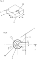
Figure 1 is a perspective view of a first embodiment of a connector. -
Figure 2 is a side view of the connector offigure 1 , -
Figure 3 is a front view of the connector offigure 1 , facing the first knob. -
Figure 4 is a sectional view of the connector offigure 1 , with the sectional plane A-A infigure 2 extending along the insertion direction and cutting through the bridge, facing the first knob. -
Figure 5 is a perspective view of a panel intended to be connected by the connector offigure 1 . -
Figure 6 is a top view detail of the panel offigure 5 . -
Figure 7 is sectional view of the panel offigure 5 , according to A-A infigure 6 . - A panel connector according to a first embodiment comprises a
first knob 1, asecond knob 2 and abridge 3 that connects thefirst knob 1 and thesecond knob 2 to one another. Theknobs - The width of the bridge 3 (24 mm in the present case, by way of example) is smaller than the width of the
first knob 1 and the width of the second knob 2 (both 60 mm in the present case, by way of example). Width is measured perpendicularly to aninsertion direction 99. - Height (measured parallel to the insertion direction 99), of the
first knob 1, of thesecond knob 2 and of thebridge 3 is the same in the present embodiment (45 mm, by way of example). However, the respective heights might also be different. - The connector is intended to be accommodated in
corresponding recesses 6 ofadjacent panels 5, so as to provide a geometrical lock situation between the connector and theadjacent panels 5, that can preferably transfer loads in different directions (e.g. tensile direction, i.e. perpendicular to joint orientation, or shear direction, i.e. parallel to joint orientation). -
Figures 5 to 7 show an example of a panel that might be connected by means of the connector. In this context, butt-joint face 51, parallel direction 58 (i.e. parallel with respect to butt-joint face 51) and perpendicular direction 59 (i.e. perpendicular with respect to butt-joint face 51) are emphasized infigure 5 . - In particular, when intended to be connected with the connector, the
panels 5 are arranged in butt-joint configuration in a same plane, wherein the respective butt-joint faces 51 are oriented parallel with each other. However, a corner joint configuration might be feasible as well. - In particular, the connector can be oriented perpendicular to main direction of the butt-
joint face 51, i.e. it can be orientated inperpendicular direction 59. - The
first knob 1 tapers along theinsertion direction 99 of the connector, and thesecond knob 2 tapers along theinsertion direction 99 of the connector. - In particular, the flanks of the
knobs recesses 6 in thepanels 5, so that thepanels 5 are drawn together when the connector is inserted. Bothknobs insertion direction 99, which is the direction the connector is intended to be inserted into thepanels 5. Accordingly, each of theknobs insertion direction 99, i.e. that end that is intended to be inserted first into thepanels 5. - In the shown first embodiment, the
first knob 1 tapers conically along theinsertion direction 99 of the connector, and thesecond knob 2 tapers conically along theinsertion direction 99 of the connector. Therecesses 6 have a correspondingly tapering outline. - In the shown embodiment, the
knobs - The
first knob 1, thesecond knob 2 and thebridge 3 are preferably monolithic, i.e. they consist of one piece. However, the connector can also consist of a plurality of separate pieces that are joined together. Preferably the connector is made of wood material, including, but not exclusive, veneer plywood made of birch or beech, CLT (cross laminated timber), GLULAM (glued laminated timber), hard or soft solid timber, molded and/or compressed parts (comprising wooden flakes or chips and organic binder such as glue). The connector can also be made of metal, ceramics, mineral material (e.g. concrete), plastic or elastomer. - The
panels 5 can be made of different wood types, including CLT (cross laminated timber), GLULAM (glued laminated timber), hard or soft solid timber, hybrid wood elements (wood in combination with concrete overlay). - In the shown first embodiment, the flanks of the
bridge 3 are parallel. Alternatively, they can also taper in theinsertion direction 99, so as to form a wedge. In this case, thebridge 3 tapers along theinsertion direction 99 of the connector. This can provide further panel alignment when the connector is inserted. - Once installed, the connector might self-lock in the final position, due to friction. Optionally, additional securing of the connector, e.g. by screwing, nailing or/and gluing can be envisaged.
- The flank surfaces of the connector, in particular the flank surfaces of
bridge 3, thefirst knob 1 and/or thesecond knob 2, can be modified to increase friction, e.g. by means of surface roughening or applying coatings (including glue or hard particles), with an aim to retain the connector inside therecesses 6 in case of tensile loads (that tend to push the connector outside ofrecess 6 due to wedge effect). Also, for the same reason, the walls of therecess 6 can be modified to increase friction, e.g. by means of surface roughening or applying coatings (including glue or hard particles). - In the shown first embodiment, an
inlay 66 is arranged within therecess 6, in particular to increase friction. Theoptional inlay 66 can, for example, be made of wood, metal, plastic, elastomer, foam. The inlay can be considered an independent invention aspect, which can be implemented independently of the constitution of the connector, in particular independently of the shape of theknobs - Arrangement of connector and panels 5 (including recesses 6) allows easy and fast alignment of panels 5 (into final position with respect to each other).
Panels 5 are initially oriented with respective butt-joint faces 51 opposite to each other with at a certain distance, e.g. 10mm, offset parallel and perpendicular to butt-joint direction. During installation, the connector is introduced into therecesses 6 and pressed into the recesses 6 (e.g. by means of hammer blows), thereby exerting a force acting perpendicular to the panel main orientation. Due to interaction of the geometry of the connector (wedge effect) and therecesses 6, thepanels 5 are drawn together and aligned to each other to final position. The connection can be unclamped by pulling the connector out of therecesses 6, which allows disassembly of connection. - In order to manufacture the geometry of the
recesses 6, at least two options appear feasible. According tooption 1, the conical contour is directly machined into wooden panels. According tooption 2, a generally cylindrical or the like contour is machined into thepanel 5, and aseparate inlay 66 with matching outer contour and conical internal contour is inserted therein. - The
inlay 66 can e.g. be made of elastomer material. An additional pre-tensioning effect of theinlay 66 can be provided by compressing it during installation.
Claims (6)
- Panel connector comprising
a first knob (1), a second knob (2) and a bridge (3) that connects the first knob (1) and the second knob (2) to one another,
characterized in that- the first knob (1) tapers along an insertion direction (99) of the connector, and- the second knob (2) tapers along the insertion direction (99) of the connector. - Connector according to claim 1,
characterized in that
the first knob (1) tapers conically along the insertion direction (99) of the connector, and the second knob (2) tapers conically along the insertion direction (99) of the connector. - Connector according to any of the preceding claims,
characterized in that
the first knob (1), the second knob (2) and the bridge are monolithic. - Connector according to any of the preceding claims,
characterized in that
the connector is made of a wood material. - Connector according to any of the preceding claims,
characterized in that
the bridge (3) tapers along the insertion direction (99) of the connector. - Panel (5), in particular wood panel, having a recess (6) for receiving a connector according to any of the preceding claims,
characterized in that
an inlay (66) is arranged within the recess (6).
Priority Applications (2)
| Application Number | Priority Date | Filing Date | Title |
|---|---|---|---|
| EP21211202.3A EP4187109A1 (en) | 2021-11-30 | 2021-11-30 | Bone shaped panel connector |
| PCT/EP2022/081954 WO2023099208A1 (en) | 2021-11-30 | 2022-11-15 | Bone shaped panel connector |
Applications Claiming Priority (1)
| Application Number | Priority Date | Filing Date | Title |
|---|---|---|---|
| EP21211202.3A EP4187109A1 (en) | 2021-11-30 | 2021-11-30 | Bone shaped panel connector |
Publications (1)
| Publication Number | Publication Date |
|---|---|
| EP4187109A1 true EP4187109A1 (en) | 2023-05-31 |
Family
ID=78851073
Family Applications (1)
| Application Number | Title | Priority Date | Filing Date |
|---|---|---|---|
| EP21211202.3A Withdrawn EP4187109A1 (en) | 2021-11-30 | 2021-11-30 | Bone shaped panel connector |
Country Status (2)
| Country | Link |
|---|---|
| EP (1) | EP4187109A1 (en) |
| WO (1) | WO2023099208A1 (en) |
Cited By (1)
| Publication number | Priority date | Publication date | Assignee | Title |
|---|---|---|---|---|
| WO2024251745A1 (en) * | 2023-06-05 | 2024-12-12 | Festool Gmbh | Connector for mechanically connecting a first component and a second component, connector assembly, blocking element, component, component assembly, and component connection |
Families Citing this family (1)
| Publication number | Priority date | Publication date | Assignee | Title |
|---|---|---|---|---|
| US12194526B1 (en) * | 2023-12-19 | 2025-01-14 | Thermwood Corporation | Methods and systems for secure connections in layer segments of cut layer additive parts |
Citations (3)
| Publication number | Priority date | Publication date | Assignee | Title |
|---|---|---|---|---|
| FR2425010A1 (en) * | 1978-05-02 | 1979-11-30 | Foucault Henri De | Furniture component assembly connector - has two pins joined by strip to fit in mating recess |
| US5149236A (en) * | 1989-02-09 | 1992-09-22 | Cassese Society | Device for assembling frames and frame mouldings and a miter cutting machine for implementing the device |
| DE202005017024U1 (en) * | 2005-10-31 | 2006-05-11 | Trümper, Jörg, Dipl.-Designer | Connecting element and detachable connection for system furniture |
-
2021
- 2021-11-30 EP EP21211202.3A patent/EP4187109A1/en not_active Withdrawn
-
2022
- 2022-11-15 WO PCT/EP2022/081954 patent/WO2023099208A1/en not_active Ceased
Patent Citations (3)
| Publication number | Priority date | Publication date | Assignee | Title |
|---|---|---|---|---|
| FR2425010A1 (en) * | 1978-05-02 | 1979-11-30 | Foucault Henri De | Furniture component assembly connector - has two pins joined by strip to fit in mating recess |
| US5149236A (en) * | 1989-02-09 | 1992-09-22 | Cassese Society | Device for assembling frames and frame mouldings and a miter cutting machine for implementing the device |
| DE202005017024U1 (en) * | 2005-10-31 | 2006-05-11 | Trümper, Jörg, Dipl.-Designer | Connecting element and detachable connection for system furniture |
Cited By (1)
| Publication number | Priority date | Publication date | Assignee | Title |
|---|---|---|---|---|
| WO2024251745A1 (en) * | 2023-06-05 | 2024-12-12 | Festool Gmbh | Connector for mechanically connecting a first component and a second component, connector assembly, blocking element, component, component assembly, and component connection |
Also Published As
| Publication number | Publication date |
|---|---|
| WO2023099208A1 (en) | 2023-06-08 |
Similar Documents
| Publication | Publication Date | Title |
|---|---|---|
| US11083287B2 (en) | Panels comprising a mechanical locking device and an assembled product comprising the panels | |
| US20220354248A1 (en) | Panels comprising a mechanical locking device and an assembled product comprising the panels | |
| EP3411599B1 (en) | A set of panels for an assembled product | |
| WO2023099208A1 (en) | Bone shaped panel connector | |
| US10876284B2 (en) | Connector for transversely screwing together two workpieces | |
| CN101333862A (en) | Device for connecting building boards, especially floor panels | |
| US10745904B2 (en) | Method and connector set for connecting beams of wood material | |
| US20160002913A1 (en) | Building element composed of two panels with a coupling strip | |
| WO2001077220A2 (en) | Composite wood product | |
| WO2023031338A1 (en) | A set of structural panels, a production method, and an assembly method | |
| US12392125B2 (en) | Connector for two components | |
| EP1404981B1 (en) | Connecting element and joint | |
| EP4187041A1 (en) | H-shaped panel connector | |
| CN120548417A (en) | Connecting device for panels | |
| US20260015853A1 (en) | Wall, ceiling, facade or roof element connection | |
| US20240392564A1 (en) | A joint for wall panels made of cross laminated timber | |
| EP4191078A1 (en) | Connection system comprising a rotation type panel connector | |
| EP4662416A1 (en) | A joint for wall panels made of cross laminated timber | |
| TWM540155U (en) | Integrated wood construction |
Legal Events
| Date | Code | Title | Description |
|---|---|---|---|
| PUAI | Public reference made under article 153(3) epc to a published international application that has entered the european phase |
Free format text: ORIGINAL CODE: 0009012 |
|
| STAA | Information on the status of an ep patent application or granted ep patent |
Free format text: STATUS: THE APPLICATION HAS BEEN PUBLISHED |
|
| AK | Designated contracting states |
Kind code of ref document: A1 Designated state(s): AL AT BE BG CH CY CZ DE DK EE ES FI FR GB GR HR HU IE IS IT LI LT LU LV MC MK MT NL NO PL PT RO RS SE SI SK SM TR |
|
| STAA | Information on the status of an ep patent application or granted ep patent |
Free format text: STATUS: THE APPLICATION IS DEEMED TO BE WITHDRAWN |
|
| 18D | Application deemed to be withdrawn |
Effective date: 20231201 |