EP4187090A1 - Compressor and compressor system - Google Patents
Compressor and compressor system Download PDFInfo
- Publication number
- EP4187090A1 EP4187090A1 EP21864239.5A EP21864239A EP4187090A1 EP 4187090 A1 EP4187090 A1 EP 4187090A1 EP 21864239 A EP21864239 A EP 21864239A EP 4187090 A1 EP4187090 A1 EP 4187090A1
- Authority
- EP
- European Patent Office
- Prior art keywords
- compressor
- flow path
- heat medium
- lubricant oil
- discharge
- Prior art date
- Legal status (The legal status is an assumption and is not a legal conclusion. Google has not performed a legal analysis and makes no representation as to the accuracy of the status listed.)
- Granted
Links
Images


Classifications
-
- F—MECHANICAL ENGINEERING; LIGHTING; HEATING; WEAPONS; BLASTING
- F04—POSITIVE - DISPLACEMENT MACHINES FOR LIQUIDS; PUMPS FOR LIQUIDS OR ELASTIC FLUIDS
- F04B—POSITIVE-DISPLACEMENT MACHINES FOR LIQUIDS; PUMPS
- F04B39/00—Component parts, details, or accessories, of pumps or pumping systems specially adapted for elastic fluids, not otherwise provided for in, or of interest apart from, groups F04B25/00 - F04B37/00
- F04B39/06—Cooling; Heating; Prevention of freezing
- F04B39/062—Cooling by injecting a liquid in the gas to be compressed
-
- F—MECHANICAL ENGINEERING; LIGHTING; HEATING; WEAPONS; BLASTING
- F04—POSITIVE - DISPLACEMENT MACHINES FOR LIQUIDS; PUMPS FOR LIQUIDS OR ELASTIC FLUIDS
- F04B—POSITIVE-DISPLACEMENT MACHINES FOR LIQUIDS; PUMPS
- F04B35/00—Piston pumps specially adapted for elastic fluids and characterised by the driving means to their working members, or by combination with, or adaptation to, specific driving engines or motors, not otherwise provided for
- F04B35/01—Piston pumps specially adapted for elastic fluids and characterised by the driving means to their working members, or by combination with, or adaptation to, specific driving engines or motors, not otherwise provided for the means being mechanical
-
- F—MECHANICAL ENGINEERING; LIGHTING; HEATING; WEAPONS; BLASTING
- F04—POSITIVE - DISPLACEMENT MACHINES FOR LIQUIDS; PUMPS FOR LIQUIDS OR ELASTIC FLUIDS
- F04B—POSITIVE-DISPLACEMENT MACHINES FOR LIQUIDS; PUMPS
- F04B35/00—Piston pumps specially adapted for elastic fluids and characterised by the driving means to their working members, or by combination with, or adaptation to, specific driving engines or motors, not otherwise provided for
- F04B35/04—Piston pumps specially adapted for elastic fluids and characterised by the driving means to their working members, or by combination with, or adaptation to, specific driving engines or motors, not otherwise provided for the means being electric
-
- F—MECHANICAL ENGINEERING; LIGHTING; HEATING; WEAPONS; BLASTING
- F04—POSITIVE - DISPLACEMENT MACHINES FOR LIQUIDS; PUMPS FOR LIQUIDS OR ELASTIC FLUIDS
- F04B—POSITIVE-DISPLACEMENT MACHINES FOR LIQUIDS; PUMPS
- F04B39/00—Component parts, details, or accessories, of pumps or pumping systems specially adapted for elastic fluids, not otherwise provided for in, or of interest apart from, groups F04B25/00 - F04B37/00
- F04B39/02—Lubrication
- F04B39/0223—Lubrication characterised by the compressor type
- F04B39/023—Hermetic compressors
- F04B39/0238—Hermetic compressors with oil distribution channels
-
- F—MECHANICAL ENGINEERING; LIGHTING; HEATING; WEAPONS; BLASTING
- F04—POSITIVE - DISPLACEMENT MACHINES FOR LIQUIDS; PUMPS FOR LIQUIDS OR ELASTIC FLUIDS
- F04B—POSITIVE-DISPLACEMENT MACHINES FOR LIQUIDS; PUMPS
- F04B39/00—Component parts, details, or accessories, of pumps or pumping systems specially adapted for elastic fluids, not otherwise provided for in, or of interest apart from, groups F04B25/00 - F04B37/00
- F04B39/02—Lubrication
- F04B39/0223—Lubrication characterised by the compressor type
- F04B39/023—Hermetic compressors
- F04B39/0238—Hermetic compressors with oil distribution channels
- F04B39/0246—Hermetic compressors with oil distribution channels in the rotating shaft
-
- F—MECHANICAL ENGINEERING; LIGHTING; HEATING; WEAPONS; BLASTING
- F04—POSITIVE - DISPLACEMENT MACHINES FOR LIQUIDS; PUMPS FOR LIQUIDS OR ELASTIC FLUIDS
- F04B—POSITIVE-DISPLACEMENT MACHINES FOR LIQUIDS; PUMPS
- F04B39/00—Component parts, details, or accessories, of pumps or pumping systems specially adapted for elastic fluids, not otherwise provided for in, or of interest apart from, groups F04B25/00 - F04B37/00
- F04B39/02—Lubrication
- F04B39/0223—Lubrication characterised by the compressor type
- F04B39/023—Hermetic compressors
- F04B39/0261—Hermetic compressors with an auxiliary oil pump
-
- F—MECHANICAL ENGINEERING; LIGHTING; HEATING; WEAPONS; BLASTING
- F04—POSITIVE - DISPLACEMENT MACHINES FOR LIQUIDS; PUMPS FOR LIQUIDS OR ELASTIC FLUIDS
- F04B—POSITIVE-DISPLACEMENT MACHINES FOR LIQUIDS; PUMPS
- F04B39/00—Component parts, details, or accessories, of pumps or pumping systems specially adapted for elastic fluids, not otherwise provided for in, or of interest apart from, groups F04B25/00 - F04B37/00
- F04B39/02—Lubrication
- F04B39/0284—Constructional details, e.g. reservoirs in the casing
-
- F—MECHANICAL ENGINEERING; LIGHTING; HEATING; WEAPONS; BLASTING
- F04—POSITIVE - DISPLACEMENT MACHINES FOR LIQUIDS; PUMPS FOR LIQUIDS OR ELASTIC FLUIDS
- F04B—POSITIVE-DISPLACEMENT MACHINES FOR LIQUIDS; PUMPS
- F04B39/00—Component parts, details, or accessories, of pumps or pumping systems specially adapted for elastic fluids, not otherwise provided for in, or of interest apart from, groups F04B25/00 - F04B37/00
- F04B39/06—Cooling; Heating; Prevention of freezing
-
- F—MECHANICAL ENGINEERING; LIGHTING; HEATING; WEAPONS; BLASTING
- F04—POSITIVE - DISPLACEMENT MACHINES FOR LIQUIDS; PUMPS FOR LIQUIDS OR ELASTIC FLUIDS
- F04B—POSITIVE-DISPLACEMENT MACHINES FOR LIQUIDS; PUMPS
- F04B39/00—Component parts, details, or accessories, of pumps or pumping systems specially adapted for elastic fluids, not otherwise provided for in, or of interest apart from, groups F04B25/00 - F04B37/00
- F04B39/06—Cooling; Heating; Prevention of freezing
- F04B39/064—Cooling by a cooling jacket in the pump casing
-
- F—MECHANICAL ENGINEERING; LIGHTING; HEATING; WEAPONS; BLASTING
- F04—POSITIVE - DISPLACEMENT MACHINES FOR LIQUIDS; PUMPS FOR LIQUIDS OR ELASTIC FLUIDS
- F04B—POSITIVE-DISPLACEMENT MACHINES FOR LIQUIDS; PUMPS
- F04B39/00—Component parts, details, or accessories, of pumps or pumping systems specially adapted for elastic fluids, not otherwise provided for in, or of interest apart from, groups F04B25/00 - F04B37/00
- F04B39/10—Adaptations or arrangements of distribution members
- F04B39/1066—Valve plates
-
- F—MECHANICAL ENGINEERING; LIGHTING; HEATING; WEAPONS; BLASTING
- F04—POSITIVE - DISPLACEMENT MACHINES FOR LIQUIDS; PUMPS FOR LIQUIDS OR ELASTIC FLUIDS
- F04B—POSITIVE-DISPLACEMENT MACHINES FOR LIQUIDS; PUMPS
- F04B39/00—Component parts, details, or accessories, of pumps or pumping systems specially adapted for elastic fluids, not otherwise provided for in, or of interest apart from, groups F04B25/00 - F04B37/00
- F04B39/12—Casings; Cylinders; Cylinder heads; Fluid connections
- F04B39/123—Fluid connections
-
- F—MECHANICAL ENGINEERING; LIGHTING; HEATING; WEAPONS; BLASTING
- F04—POSITIVE - DISPLACEMENT MACHINES FOR LIQUIDS; PUMPS FOR LIQUIDS OR ELASTIC FLUIDS
- F04B—POSITIVE-DISPLACEMENT MACHINES FOR LIQUIDS; PUMPS
- F04B39/00—Component parts, details, or accessories, of pumps or pumping systems specially adapted for elastic fluids, not otherwise provided for in, or of interest apart from, groups F04B25/00 - F04B37/00
- F04B39/12—Casings; Cylinders; Cylinder heads; Fluid connections
- F04B39/125—Cylinder heads
-
- F—MECHANICAL ENGINEERING; LIGHTING; HEATING; WEAPONS; BLASTING
- F04—POSITIVE - DISPLACEMENT MACHINES FOR LIQUIDS; PUMPS FOR LIQUIDS OR ELASTIC FLUIDS
- F04B—POSITIVE-DISPLACEMENT MACHINES FOR LIQUIDS; PUMPS
- F04B41/00—Pumping installations or systems specially adapted for elastic fluids
- F04B41/06—Combinations of two or more pumps
-
- F—MECHANICAL ENGINEERING; LIGHTING; HEATING; WEAPONS; BLASTING
- F04—POSITIVE - DISPLACEMENT MACHINES FOR LIQUIDS; PUMPS FOR LIQUIDS OR ELASTIC FLUIDS
- F04B—POSITIVE-DISPLACEMENT MACHINES FOR LIQUIDS; PUMPS
- F04B53/00—Component parts, details or accessories not provided for in, or of interest apart from, groups F04B1/00 - F04B23/00 or F04B39/00 - F04B47/00
- F04B53/08—Cooling; Heating; Preventing freezing
-
- F—MECHANICAL ENGINEERING; LIGHTING; HEATING; WEAPONS; BLASTING
- F04—POSITIVE - DISPLACEMENT MACHINES FOR LIQUIDS; PUMPS FOR LIQUIDS OR ELASTIC FLUIDS
- F04B—POSITIVE-DISPLACEMENT MACHINES FOR LIQUIDS; PUMPS
- F04B53/00—Component parts, details or accessories not provided for in, or of interest apart from, groups F04B1/00 - F04B23/00 or F04B39/00 - F04B47/00
- F04B53/18—Lubricating
-
- F—MECHANICAL ENGINEERING; LIGHTING; HEATING; WEAPONS; BLASTING
- F25—REFRIGERATION OR COOLING; COMBINED HEATING AND REFRIGERATION SYSTEMS; HEAT PUMP SYSTEMS; MANUFACTURE OR STORAGE OF ICE; LIQUEFACTION SOLIDIFICATION OF GASES
- F25B—REFRIGERATION MACHINES, PLANTS OR SYSTEMS; COMBINED HEATING AND REFRIGERATION SYSTEMS; HEAT PUMP SYSTEMS
- F25B31/00—Compressor arrangements
- F25B31/002—Lubrication
-
- F—MECHANICAL ENGINEERING; LIGHTING; HEATING; WEAPONS; BLASTING
- F25—REFRIGERATION OR COOLING; COMBINED HEATING AND REFRIGERATION SYSTEMS; HEAT PUMP SYSTEMS; MANUFACTURE OR STORAGE OF ICE; LIQUEFACTION SOLIDIFICATION OF GASES
- F25B—REFRIGERATION MACHINES, PLANTS OR SYSTEMS; COMBINED HEATING AND REFRIGERATION SYSTEMS; HEAT PUMP SYSTEMS
- F25B31/00—Compressor arrangements
- F25B31/006—Cooling of compressor or motor
-
- F—MECHANICAL ENGINEERING; LIGHTING; HEATING; WEAPONS; BLASTING
- F04—POSITIVE - DISPLACEMENT MACHINES FOR LIQUIDS; PUMPS FOR LIQUIDS OR ELASTIC FLUIDS
- F04B—POSITIVE-DISPLACEMENT MACHINES FOR LIQUIDS; PUMPS
- F04B27/00—Multi-cylinder pumps specially adapted for elastic fluids and characterised by number or arrangement of cylinders
- F04B27/04—Multi-cylinder pumps specially adapted for elastic fluids and characterised by number or arrangement of cylinders having cylinders in star- or fan-arrangement
- F04B27/053—Multi-cylinder pumps specially adapted for elastic fluids and characterised by number or arrangement of cylinders having cylinders in star- or fan-arrangement with an actuating element at the inner ends of the cylinders
- F04B27/0536—Multi-cylinder pumps specially adapted for elastic fluids and characterised by number or arrangement of cylinders having cylinders in star- or fan-arrangement with an actuating element at the inner ends of the cylinders with two or more series radial piston-cylinder units
- F04B27/0538—Multi-cylinder pumps specially adapted for elastic fluids and characterised by number or arrangement of cylinders having cylinders in star- or fan-arrangement with an actuating element at the inner ends of the cylinders with two or more series radial piston-cylinder units directly located side-by-side
Definitions
- the present disclosure relates to a compressor and a compressor system.
- Patent Document 1, 2 discloses a configuration for suppressing overheating by injecting a refrigerant liquid into a discharge space in a head cover and cooling a compressed discharge gas with latent heat of vaporization of the refrigerant liquid.
- Patent Document 1 it is possible to cool the discharge gas, and it is possible to suppress overheating of the compressor.
- a large amount of frost may occur on a surface of the compressor (for example, a surface of the head cover or the casing).
- Such configuration where the large amount of frost occurs is not preferable.
- the present disclosure has been made in view of the above-described problems, and the object of the present disclosure is to suppresses the occurrence of frost on the surface of the compressor when the compressed discharge gas is cooled by injecting the refrigerant liquid into the discharge space of the compressor.
- a compressor includes: a discharge valve; a discharge space formed downstream of the discharge valve; a liquid injection hole for injecting a refrigerant liquid into the discharge space; and a heat medium flow path located opposite to the discharge space across a partition wall forming the discharge space.
- a compressor system is a compressor system, including: a low-stage compression part; and a high-stage compression part. At least the low-stage compression part is constituted by the compressor as defined in the above.
- the "low-stage compression part” and the “high-stage compression part” include a low-stage compressor and a high-stage compressor each having an independent casing, and a low-stage compressor and a high-stage compressor housed in a single housing casing, for example, a reciprocating compressor.
- an expression of relative or absolute arrangement such as “in a direction”, “along a direction”, “parallel”, “orthogonal”, “centered”, “concentric” and “coaxial” shall not be construed as indicating only the arrangement in a strict literal sense, but also includes a state where the arrangement is relatively displaced by a tolerance, or by an angle or a distance whereby it is possible to achieve the same function.
- an expression of an equal state such as “same”, “equal”, and “uniform” shall not be construed as indicating only the state in which the feature is strictly equal, but also includes a state in which there is a tolerance or a difference that can still achieve the same function.
- an expression of a shape such as a rectangular shape or a tubular shape shall not be construed as only the geometrically strict shape, but also includes a shape with unevenness or chamfered corners within the range in which the same effect can be achieved.
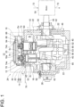
- FIG. 1 is a front cross-sectional view of a compressor 10 according to an embodiment
- FIG. 2 is a system diagram showing a lubricant oil supply system for the compressor 10 according to an embodiment.
- the compressor 10 is, for example, a compressor incorporated in a refrigeration device or the like and configured to compress a refrigerant gas.
- the compressor 10 includes a discharge valve 12, and a discharge space Sv is formed downstream of the discharge valve 12.
- a liquid injection hole 14 for injecting the refrigerant liquid into the discharge space Sv is formed in a compressor casing 16.
- a condensate liquid of the refrigerant gas which is the gas to be compressed, is injected from the liquid injection hole 14 into the discharge space Sv.
- the condensate liquid evaporates in the high-temperature discharge space Sv, absorbs latent heat of vaporization from a discharge gas Gv, and cools the discharge gas Gv.
- frost may occur on a surface of a casing 18 forming the discharge space Sv, as described above.
- the compressor 10 in order to suppress the occurrence of frost on the casing 18, the compressor 10 includes a heat medium flow path 20 located opposite to the discharge space Sv across a partition wall 18a forming the discharge space Sv.
- a heat medium flow path 20 located opposite to the discharge space Sv across a partition wall 18a forming the discharge space Sv.
- the compressor 10 includes a lubricant oil flow path 22 through which lubricant oil r supplied to a part to be lubricated flows.
- the heat medium flow path 20 is disposed in series or parallel with the lubricant oil flow path 22.
- the lubricant oil r which has absorbed the heat of the part to be lubricated in the compressor 10 by lubricating and cooling the part to be lubricated, to flow through the heat medium flow path 20, the temperature of the casing 18, which includes the partition wall 18a forming the discharge space Sv, can be increased by potential heat of the lubricant oil r. Therefore, it is possible to suppress the occurrence of frost on the surface of the casing 18 of the compressor 10.
- the part to be lubricated of the compressor 10 includes, as an example, at least either of a rotor or a rotor support portion.
- the parts to be lubricated are a crank shaft 48 and a thrust bearing 50, which will be described later.
- the part to be lubricated may be either the crank shaft 48 or the thrust bearing 50.
- the heat medium flow path 20 is arranged in series with the lubricant oil flow path 22, and a circulation path 24 for the lubricant oil r including the part to be lubricated of the compressor 10, the heat medium flow path 20, and the lubricant oil flow path 22 is formed. Further, the circulation path 24 is provided with an oil pump 26 for circulating the lubricant oil r. According to the present embodiment, since the lubricant oil r circulating in the circulation path 24 by the oil pump 26 is cooled in the heat medium flow path 20, a dedicated oil cooler is not required and a cost can be reduced.
- FIG. 3 shows an embodiment in which the heat medium flow path 20 is disposed in parallel with the circulation path 24.
- an oil cooler 28 is provided in the circulation path 24 for the lubricant oil flowing through the part to be lubricated of the compressor 10.
- the lubricant oil r flowing through the circulation path 24 flows through the part to be lubricated of the compressor 10, cools the part to be lubricated, is heated, and is cooled by the oil cooler 28.
- the compressor 10 includes a branch path 30 branching off from the circulation path 24, communicating with the heat medium flow path 20, and merging with the circulation path 24 again.
- the lubricant oil r flowing through the branch path 30 exchanges heat with the discharge gas Gv in the heat medium flow path 20 to heat the discharge gas Gv.
- the discharge gas Gv is heated by the heat medium flow path 20, it is possible to suppress frost generated on the partition wall 18a or the surface of the casing 18 including the partition wall 18a. Meanwhile, the oil cooler 28 plays the main role of cooling the lubricant oil r.
- the circulation path 24 and the branch path 30 may be provided with flow control valves 32 and 34, respectively. Only one of the flow control valve 32 and the flow control valve 34 may be provided. Since these flow control valves 32 and 34 are provided, it is possible to control the flow rate of the lubricant oil r flowing through the branch path 30, making it possible to control the heating capacity of the heat medium flow path 20. It is preferable that the branching portion and the merging portion of the branch path 30 with respect to the circulation path 24 are disposed such that the lubricant oil r having a temperature suitable for a heating condition of the heat medium flow path 20 flows through the heat medium flow path 20.
- the compressor 10 is the reciprocating compressor.
- the compressor 10 is configured such that a cylinder 40 is housed inside the compressor casing 16 and a piston 42 reciprocates inside the cylinder 40.
- a valve plate 44 for supporting the discharge valve 12 is disposed at one end of the cylinder 40 (an upper end of the cylinder 40 in the figure) and further, a head cover is provided as the casing 18 which includes the partition wall 18a forming the discharge space Sv.
- the temperature of the head cover serving as the casing 18 can be increased by the heat medium flowing through the heat medium flow path 20, making it possible to suppress the occurrence of frost on the surface of the head cover.
- the casing 18 of the compressor 10 is the head cover, but the casing 18 is not limited to the head cover.
- the casing 18 may be called the head cover 18.
- a crankcase 46 is disposed below the compressor casing 16.
- the crank shaft 48 is supported by the crankcase 46 via the thrust bearing 50.
- An oil reservoir Os of the lubricant oil r is formed at the bottom of the crankcase 46.
- the piston 42 is connected to the crank shaft 48 via a connecting rod 52, and the piston 42 reciprocates inside the cylinder 40 as the crank shaft 48 rotates.
- two cylinders 40 are disposed in parallel, and the pistons 42 of the two cylinders 40 are connected to the crank shaft 48 so as to reciprocate in phases different by 180° at a rotation angle of the crank shaft 48.
- a motor 54 for rotary driving the crank shaft 48 is disposed at one end of the crank shaft 48 outside the crankcase 46.
- the oil pump 26 is disposed at another end of the crank shaft 48 and is operated by the rotation of the crank shaft 48.
- an oil filter 56 is disposed in the oil reservoir Os, and the oil pump 26 sucks up the lubricant oil r from the oil reservoir Os into the lubricant oil flow path 22.
- the parts to be lubricated, such as the crank shaft 48 and the thrust bearing 50, are formed with oil passages 60 and 62. The lubricant oil r discharged from the oil pump 26 to the lubricant oil flow path 22 is supplied to these oil passages. As shown in FIG.
- a part of the oil passage 60 is introduced to the piston 42 via a crank pin 53. Further, the lubricant oil r is supplied from the lubricant oil flow path 22 to the heat medium flow path 20 to heat the discharge gas Gv. The lubricant oil r that has passed through the heat medium flow path 20 returns to the oil reservoir Os via the oil passages 60 and 62, or the like. Thus, the circulation path 24 for the lubricant oil r described above is formed.
- the suction space Si is formed outside the cylinder 40, and if the piston 42 descends and a compression space in the cylinder 40 is decompressed, the refrigerant gas, which is the gas to be compressed, is sucked from the suction space Si into a compression space in the cylinder 40 through a suction valve 63.
- the refrigerant gas sucked into the compression space is compressed in the compression space and discharged to the discharge space Sv.
- a disc-shaped valve cage 66 is pressed and fixed to an upper surface of the valve plate 44 by a coil spring 64 to block an opening of the valve plate 44.
- a truncated conical valve plate 70 is joined to a lower surface of the valve cage 66 by a bolt 68.
- a discharge gas passage is formed in the valve cage 66 and the discharge valve 12 is mounted thereon. If the piston 42 rises and a gas pressure in a cylinder chamber increases, the discharge valve 12 is pushed up to discharge the refrigerant gas into the discharge gas passage.
- the compressor 10 includes a coolant flow path 72 for cooling the compressor driving motor 54.
- the coolant flow path 72 communicates with the heat medium flow path 20.
- a liquid coolant which has cooled the motor 54 and sucked a potential heat of the motor 54, is flowed through the heat medium flow path 20 and the casing 18, which includes the partition wall 18a forming the discharge space Sv, can be increased in temperature by potential heat of the coolant, making it possible to suppress the occurrence of frost on the surface of the casing 18 of the compressor 10.
- heated hot water, an antifreeze liquid, or the like which is used as a cooling liquid in another part of the compressor 10, may be supplied to the heat medium flow path 20 to heat the discharge space Sv.
- a jacket cover 74 internally having a heat medium introduction space is disposed on an outer surface of the head cover serving as the casing 18.
- the heat medium introduction space forms the heat medium flow path 20.
- the heat medium flow path 20 can be formed simply by mounting the jacket cover 74 on the existing compressor and the other parts do not need modification, making it possible to easily form the heat medium flow path 20.
- the jacket cover 74 is formed with an inlet hole 74a and an outlet hole 74b of the heat medium flow path 20, and the lubricant oil flow path 22 is connected to the inlet hole 74a and the outlet hole 74b. Then, the lubricant oil r is supplied from the inlet hole 74a to the heat medium introduction space (heat medium flow path 20) and is discharged from the outlet hole 74b to the lubricant oil flow path 22.
- the inlet hole 74a and the outlet hole 74b are, respectively, formed at both end portions of the jacket cover 74 away from each other.
- the liquid injection hole 14 for injecting the refrigerant liquid into the discharge space Sv includes a through hole 14a formed in the valve plate 44, and a communication hole 14b disposed in a wall portion of the compressor casing 16 and communicating with the through hole 14a to cause the through hole 14a to communicate with an external space.
- the communication hole 14b is connected to a refrigerant path 76 branching off from an outlet-side refrigerant path of the liquid receiver 88, and the refrigerant liquid is supplied from the refrigerant path 76 to the liquid injection hole 14.
- one end of the through hole 14a is open to the discharge space Sv, and another end of the through hole 14a is formed so as to communicate with the communication hole 14b.
- the liquid injection hole 14 can be formed at a position avoiding the head cover 18. If the heat medium flow path 20 needs to be disposed on the head cover 18 side and the liquid injection hole 14 is disposed on the head cover 18 side, the installation positions of the heat medium flow path 20 and the liquid injection hole 14 interfere. In the present embodiment, since the liquid injection hole 14 can be formed at the position on the valve plate 44 side avoiding the head cover 18, it is possible to realize a layout of the liquid injection hole 14 that can avoid the interference with the heat medium flow path 20.
- the communication hole 14b is formed in an upper end portion of the casing surrounding the cylinder 40, which is a part of the compressor casing 16.
- the communication hole 14b may be formed in the valve plate 44.
- the installation position of the liquid injection hole 14 is not limited to that of the above embodiment, and may be formed in another position, for example, in the head cover 18.
- an outer peripheral edge portion of the valve plate 44 is interposed between the compressor casing 16 and an outer peripheral edge portion of the head cover 18. If the outer peripheral edge portion of the valve plate 44 is thus disposed in such a manner as to be exposed to the external space of the compressor 10, processing for opening the liquid injection hole 14 to the external space of the compressor 10 is facilitated. Further, as shown in FIG. 1 , since the outer peripheral edge portions of the compressor casing 16, the valve plate 44, and the head cover 18 are laminated in three layers, the outer peripheral edge portions of these three layers can easily be joined by fastening together with a bolt 78. Thus, the valve plate 44 is mounted easily.
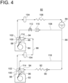
- a compressor system 80 shown in FIG. 4 is a two-stage compressor system which includes a low-stage compressor 82 and a high-stage compressor 84, and in which the refrigerant gas is the gas to be compressed, and the low-stage compressor 82 is constituted by the compressor 10 according to the above embodiment. Since the low-stage compressor 82 is constituted by the compressor 10, it is possible to suppress the occurrence of frost on the surface of the casing 18, which includes the partition wall forming the discharge space, in the low-stage compressor 82.
- the low-stage compressor 82 and the high-stage compressor 84 are each constituted by the reciprocating compressor.
- a liquid receiver 88 is disposed on a refrigerant circulation path 86, and the refrigerant liquid in the liquid receiver 88 is decompressed by an expansion valve 90 through the refrigerant circulation path 86, and evaporates by absorbing latent heat of vaporization from a load in an evaporator 92.
- the refrigerant gas evaporated in the evaporator 92 is sucked into a suction chamber 94 of the low-stage compressor 82, is further sucked into a cylinder 98 via a suction valve 96, and is compressed.
- the refrigerant gas compressed by the cylinder 98 is discharged to a discharge chamber 102 via a discharge valve 100 and discharged from the discharge chamber 102 to the refrigerant circulation path 86.
- the refrigerant gas discharged to the refrigerant circulation path 86 is sucked into the suction chamber 94 of the high-stage compressor 84 after the lubricant oil is separated by an oil separator 104.
- the refrigerant gas sucked into the suction chamber 94 of the high-stage compressor 84 is further sucked into the cylinder 98 via the suction valve 96, is compressed, and is discharged from the discharge chamber 102 to the refrigerant circulation path 86.
- the refrigerant gas discharged to the refrigerant circulation path 86 is cooled and liquefied by the condenser 106 after the lubricant oil is separated by the oil separator 104.
- a branch path 108 branching off from the refrigerant circulation path 86 is disposed downstream of the liquid receiver 88, and the branch path 108 is provided with a liquid pump 110 and a pressure regulating valve 112.
- the branch path 108 is connected to the discharge chamber 102 of the high-stage compressor 84, and the refrigerant liquid is pressurized to have a higher pressure than the discharge chamber 102 of the high-stage compressor 84 by controlling a rotation speed of the oil pump 26 and the pressure control with the pressure regulating valve 112, and is injected into the discharge chamber 102 from an injection nozzle 114 disposed in the discharge chamber 102.
- the injected refrigerant liquid evaporates under the temperature and pressure conditions of the discharge chamber 102 to cool the discharge space.
- the refrigerant circulation path 86 is provided with a branch path 116 branching off from the refrigerant circulation path 86 at a downstream position of the branch path 108.
- the branch path 116 is connected to the injection nozzle 114 disposed on an inner wall surface of the discharge chamber 102 of the low-stage compressor 82. Since the discharge chamber 102 of the low-stage compressor 82 has the lower pressure than the branch path 116, the refrigerant liquid can be supplied to the discharge chamber 102 at the same pressure without increasing the pressure.
- the discharge chamber 102 of the low-stage compressor 82 is cooled by evaporation of the refrigerant liquid injected from the injection nozzle 114 under the temperature and pressure conditions of the discharge chamber 102.
- the low-stage compressor 82 is constituted by the compressor 10 according to each of the above-described embodiments, it is possible to suppress frost generated on the surface of the casing (head cover) 18 of the compressor 10.
- the low-stage compressor 82 and the high-stage compressor 84 may constitute a single-machine two-stage compressor in which the low-stage compressor and the high-stage compressor are housed in one casing.
- a compressor system may be configured in which one cylinder 40 is the low-stage compressor and the another cylinder is the high-stage compressor.
Landscapes
- Engineering & Computer Science (AREA)
- Mechanical Engineering (AREA)
- General Engineering & Computer Science (AREA)
- Physics & Mathematics (AREA)
- Thermal Sciences (AREA)
- Compressor (AREA)
- Applications Or Details Of Rotary Compressors (AREA)
Abstract
Description
- The present disclosure relates to a compressor and a compressor system.
- In a compressor, if the compressor is overheated by a compressed gas having a high temperature and a high pressure, the density of a gas to be compressed sucked into the compressor decreases, causing a decrease in efficiency of the compressor. Therefore, for example, in a reciprocating compressor, as a means for suppressing overheating of the compressor, a pipe for flowing cooling water is provided inside a crankcase or a head cover. For example, Patent Document 1, 2 discloses a configuration for suppressing overheating by injecting a refrigerant liquid into a discharge space in a head cover and cooling a compressed discharge gas with latent heat of vaporization of the refrigerant liquid.
-
- Patent Document 1:
JP2010-53765A - Patent Document 2:
JP2011-163192A - According to the configuration disclosed in Patent Document 1, 2, it is possible to cool the discharge gas, and it is possible to suppress overheating of the compressor. However, due to an influence of cooling, a large amount of frost may occur on a surface of the compressor (for example, a surface of the head cover or the casing). Such configuration where the large amount of frost occurs is not preferable.
- The present disclosure has been made in view of the above-described problems, and the object of the present disclosure is to suppresses the occurrence of frost on the surface of the compressor when the compressed discharge gas is cooled by injecting the refrigerant liquid into the discharge space of the compressor.
- In order to achieve the above object, a compressor according to the present disclosure includes: a discharge valve; a discharge space formed downstream of the discharge valve; a liquid injection hole for injecting a refrigerant liquid into the discharge space; and a heat medium flow path located opposite to the discharge space across a partition wall forming the discharge space.
- Further, a compressor system according to the present disclosure is a compressor system, including: a low-stage compression part; and a high-stage compression part. At least the low-stage compression part is constituted by the compressor as defined in the above.
- Herein, the "low-stage compression part" and the "high-stage compression part" include a low-stage compressor and a high-stage compressor each having an independent casing, and a low-stage compressor and a high-stage compressor housed in a single housing casing, for example, a reciprocating compressor.
- With the compressor and the compressor system according to the present disclosure, since the above-described heat medium flow path is provided, it is possible to increase the temperature of the compressor casing which includes the partition wall forming the discharge space, making it possible to suppress the occurrence of frost on the surface of the compressor.
-
-
FIG. 1 is a front cross-sectional view of a reciprocating compressor according to an embodiment. -
FIG. 2 is a system diagram showing a lubricant oil supply system for the reciprocating compressor according to an embodiment. -
FIG. 3 is a system diagram showing the lubricant oil supply system for the reciprocating compressor according to an embodiment. -
FIG. 4 is a system diagram of a compressor system according to an embodiment. - Some embodiments of the present invention will be described below with reference to the accompanying drawings. It is intended, however, that unless particularly specified, dimensions, materials, shapes, relative positions and the like of components described or shown in the drawings as the embodiments shall be interpreted as illustrative only and not intended to limit the scope of the present invention.
- For instance, an expression of relative or absolute arrangement such as "in a direction", "along a direction", "parallel", "orthogonal", "centered", "concentric" and "coaxial" shall not be construed as indicating only the arrangement in a strict literal sense, but also includes a state where the arrangement is relatively displaced by a tolerance, or by an angle or a distance whereby it is possible to achieve the same function.
- For instance, an expression of an equal state such as "same", "equal", and "uniform" shall not be construed as indicating only the state in which the feature is strictly equal, but also includes a state in which there is a tolerance or a difference that can still achieve the same function.
- Further, for instance, an expression of a shape such as a rectangular shape or a tubular shape shall not be construed as only the geometrically strict shape, but also includes a shape with unevenness or chamfered corners within the range in which the same effect can be achieved.
- On the other hand, an expressions such as "comprising", "including", "having", "containing", and "constituting" one constitutional element are not intended to be exclusive of other constitutional elements.
-
FIG. 1 is a front cross-sectional view of acompressor 10 according to an embodiment, andFIG. 2 is a system diagram showing a lubricant oil supply system for thecompressor 10 according to an embodiment. InFIGs. 1 and2 , thecompressor 10 is, for example, a compressor incorporated in a refrigeration device or the like and configured to compress a refrigerant gas. Thecompressor 10 includes adischarge valve 12, and a discharge space Sv is formed downstream of thedischarge valve 12. Aliquid injection hole 14 for injecting the refrigerant liquid into the discharge space Sv is formed in acompressor casing 16. In the present embodiment, as in Patent Documents 1 and 2, a condensate liquid of the refrigerant gas, which is the gas to be compressed, is injected from theliquid injection hole 14 into the discharge space Sv. The condensate liquid evaporates in the high-temperature discharge space Sv, absorbs latent heat of vaporization from a discharge gas Gv, and cools the discharge gas Gv. Thus, it is possible to suppress overheating of the discharge gas Gv. However, as the case now stands, frost may occur on a surface of acasing 18 forming the discharge space Sv, as described above. - Therefore, in order to suppress the occurrence of frost on the
casing 18, thecompressor 10 includes a heatmedium flow path 20 located opposite to the discharge space Sv across apartition wall 18a forming the discharge space Sv. By flowing a heat medium through the heatmedium flow path 20, the temperature of thecasing 18 including thepartition wall 18a is increased, making it possible to suppress the occurrence of frost on the surface of thecasing 18. - In an embodiment, the
compressor 10 includes a lubricantoil flow path 22 through which lubricant oil r supplied to a part to be lubricated flows. The heatmedium flow path 20 is disposed in series or parallel with the lubricantoil flow path 22. According to the present embodiment, since it is possible to cause the lubricant oil r, which has absorbed the heat of the part to be lubricated in thecompressor 10 by lubricating and cooling the part to be lubricated, to flow through the heatmedium flow path 20, the temperature of thecasing 18, which includes thepartition wall 18a forming the discharge space Sv, can be increased by potential heat of the lubricant oil r. Therefore, it is possible to suppress the occurrence of frost on the surface of thecasing 18 of thecompressor 10. The part to be lubricated of thecompressor 10 includes, as an example, at least either of a rotor or a rotor support portion. As a more specific example, the parts to be lubricated are acrank shaft 48 and a thrust bearing 50, which will be described later. The part to be lubricated may be either thecrank shaft 48 or the thrust bearing 50. - In an embodiment, as shown in
FIG. 2 , the heatmedium flow path 20 is arranged in series with the lubricantoil flow path 22, and acirculation path 24 for the lubricant oil r including the part to be lubricated of thecompressor 10, the heatmedium flow path 20, and the lubricantoil flow path 22 is formed. Further, thecirculation path 24 is provided with anoil pump 26 for circulating the lubricant oil r. According to the present embodiment, since the lubricant oil r circulating in thecirculation path 24 by theoil pump 26 is cooled in the heatmedium flow path 20, a dedicated oil cooler is not required and a cost can be reduced. -
FIG. 3 shows an embodiment in which the heatmedium flow path 20 is disposed in parallel with thecirculation path 24. In the present embodiment, anoil cooler 28 is provided in thecirculation path 24 for the lubricant oil flowing through the part to be lubricated of thecompressor 10. The lubricant oil r flowing through thecirculation path 24 flows through the part to be lubricated of thecompressor 10, cools the part to be lubricated, is heated, and is cooled by theoil cooler 28. Further, thecompressor 10 includes abranch path 30 branching off from thecirculation path 24, communicating with the heatmedium flow path 20, and merging with thecirculation path 24 again. The lubricant oil r flowing through thebranch path 30 exchanges heat with the discharge gas Gv in the heatmedium flow path 20 to heat the discharge gas Gv. According to the present embodiment, since the discharge gas Gv is heated by the heatmedium flow path 20, it is possible to suppress frost generated on thepartition wall 18a or the surface of thecasing 18 including thepartition wall 18a. Meanwhile, theoil cooler 28 plays the main role of cooling the lubricant oil r. - As shown in
FIG. 3 , thecirculation path 24 and thebranch path 30 may be provided withflow control valves flow control valve 32 and theflow control valve 34 may be provided. Since theseflow control valves branch path 30, making it possible to control the heating capacity of the heatmedium flow path 20. It is preferable that the branching portion and the merging portion of thebranch path 30 with respect to thecirculation path 24 are disposed such that the lubricant oil r having a temperature suitable for a heating condition of the heatmedium flow path 20 flows through the heatmedium flow path 20. - In an embodiment, as shown in
FIGs. 1 and2 , thecompressor 10 is the reciprocating compressor. In this case, thecompressor 10 is configured such that acylinder 40 is housed inside thecompressor casing 16 and apiston 42 reciprocates inside thecylinder 40. Avalve plate 44 for supporting thedischarge valve 12 is disposed at one end of the cylinder 40 (an upper end of thecylinder 40 in the figure) and further, a head cover is provided as thecasing 18 which includes thepartition wall 18a forming the discharge space Sv. According to thecompressor 10 which is the reciprocating compressor, the temperature of the head cover serving as thecasing 18 can be increased by the heat medium flowing through the heatmedium flow path 20, making it possible to suppress the occurrence of frost on the surface of the head cover. In the present embodiment, thecasing 18 of thecompressor 10 is the head cover, but thecasing 18 is not limited to the head cover. Hereinafter, thecasing 18 may be called thehead cover 18. - Further, as shown in
FIGs. 1 and2 , acrankcase 46 is disposed below thecompressor casing 16. Thecrank shaft 48 is supported by thecrankcase 46 via thethrust bearing 50. An oil reservoir Os of the lubricant oil r is formed at the bottom of thecrankcase 46. Thepiston 42 is connected to thecrank shaft 48 via a connectingrod 52, and thepiston 42 reciprocates inside thecylinder 40 as thecrank shaft 48 rotates. In the exemplary embodiments shown inFIGs. 1 and2 , twocylinders 40 are disposed in parallel, and thepistons 42 of the twocylinders 40 are connected to thecrank shaft 48 so as to reciprocate in phases different by 180° at a rotation angle of thecrank shaft 48. Further, amotor 54 for rotary driving thecrank shaft 48 is disposed at one end of thecrank shaft 48 outside thecrankcase 46. Theoil pump 26 is disposed at another end of thecrank shaft 48 and is operated by the rotation of thecrank shaft 48. - As shown in
FIG. 2 , anoil filter 56 is disposed in the oil reservoir Os, and theoil pump 26 sucks up the lubricant oil r from the oil reservoir Os into the lubricantoil flow path 22. Apressure regulating valve 58 disposed at a terminating end of the lubricantoil flow path 22 regulates an oil pressure of the lubricant oil r flowing through thecirculation path 24. The parts to be lubricated, such as thecrank shaft 48 and thethrust bearing 50, are formed withoil passages oil pump 26 to the lubricantoil flow path 22 is supplied to these oil passages. As shown inFIG. 2 , a part of theoil passage 60 is introduced to thepiston 42 via acrank pin 53. Further, the lubricant oil r is supplied from the lubricantoil flow path 22 to the heatmedium flow path 20 to heat the discharge gas Gv. The lubricant oil r that has passed through the heatmedium flow path 20 returns to the oil reservoir Os via theoil passages circulation path 24 for the lubricant oil r described above is formed. - As shown in
FIG. 1 , the suction space Si is formed outside thecylinder 40, and if thepiston 42 descends and a compression space in thecylinder 40 is decompressed, the refrigerant gas, which is the gas to be compressed, is sucked from the suction space Si into a compression space in thecylinder 40 through asuction valve 63. The refrigerant gas sucked into the compression space is compressed in the compression space and discharged to the discharge space Sv. A disc-shapedvalve cage 66 is pressed and fixed to an upper surface of thevalve plate 44 by acoil spring 64 to block an opening of thevalve plate 44. A truncatedconical valve plate 70 is joined to a lower surface of thevalve cage 66 by abolt 68. A discharge gas passage is formed in thevalve cage 66 and thedischarge valve 12 is mounted thereon. If thepiston 42 rises and a gas pressure in a cylinder chamber increases, thedischarge valve 12 is pushed up to discharge the refrigerant gas into the discharge gas passage. - In an embodiment, as shown in
FIGs. 1 and2 , thecompressor 10 includes acoolant flow path 72 for cooling thecompressor driving motor 54. Thecoolant flow path 72 communicates with the heatmedium flow path 20. In the present embodiment, a liquid coolant, which has cooled themotor 54 and sucked a potential heat of themotor 54, is flowed through the heatmedium flow path 20 and thecasing 18, which includes thepartition wall 18a forming the discharge space Sv, can be increased in temperature by potential heat of the coolant, making it possible to suppress the occurrence of frost on the surface of thecasing 18 of thecompressor 10. - Furthermore, as another embodiment, for example, heated hot water, an antifreeze liquid, or the like, which is used as a cooling liquid in another part of the
compressor 10, may be supplied to the heatmedium flow path 20 to heat the discharge space Sv. - In an embodiment, as shown in
FIG. 1 , ajacket cover 74 internally having a heat medium introduction space is disposed on an outer surface of the head cover serving as thecasing 18. The heat medium introduction space forms the heatmedium flow path 20. According to the present embodiment, the heatmedium flow path 20 can be formed simply by mounting thejacket cover 74 on the existing compressor and the other parts do not need modification, making it possible to easily form the heatmedium flow path 20. - In the exemplary embodiment shown in
FIG. 1 , thejacket cover 74 is formed with aninlet hole 74a and anoutlet hole 74b of the heatmedium flow path 20, and the lubricantoil flow path 22 is connected to theinlet hole 74a and theoutlet hole 74b. Then, the lubricant oil r is supplied from theinlet hole 74a to the heat medium introduction space (heat medium flow path 20) and is discharged from theoutlet hole 74b to the lubricantoil flow path 22. As shown inFIG. 1 , theinlet hole 74a and theoutlet hole 74b are, respectively, formed at both end portions of thejacket cover 74 away from each other. Thus, it is possible to increase a residence time of the lubricant oil r in the heat medium introduction space, and it is possible to improve the heat exchange rate with the discharge gas Gv. - In an embodiment, as shown in
FIG. 1 , theliquid injection hole 14 for injecting the refrigerant liquid into the discharge space Sv includes a throughhole 14a formed in thevalve plate 44, and acommunication hole 14b disposed in a wall portion of thecompressor casing 16 and communicating with the throughhole 14a to cause the throughhole 14a to communicate with an external space. As will be described later, in a heat pump device including thecompressor 10, thecommunication hole 14b is connected to arefrigerant path 76 branching off from an outlet-side refrigerant path of theliquid receiver 88, and the refrigerant liquid is supplied from therefrigerant path 76 to theliquid injection hole 14. - In an embodiment, as shown in
FIG. 1 , one end of the throughhole 14a is open to the discharge space Sv, and another end of the throughhole 14a is formed so as to communicate with thecommunication hole 14b. - According to the present embodiment, the
liquid injection hole 14 can be formed at a position avoiding thehead cover 18. If the heatmedium flow path 20 needs to be disposed on thehead cover 18 side and theliquid injection hole 14 is disposed on thehead cover 18 side, the installation positions of the heatmedium flow path 20 and theliquid injection hole 14 interfere. In the present embodiment, since theliquid injection hole 14 can be formed at the position on thevalve plate 44 side avoiding thehead cover 18, it is possible to realize a layout of theliquid injection hole 14 that can avoid the interference with the heatmedium flow path 20. - In the exemplary embodiment shown in
FIG. 1 , thecommunication hole 14b is formed in an upper end portion of the casing surrounding thecylinder 40, which is a part of thecompressor casing 16. On the other hand, thecommunication hole 14b may be formed in thevalve plate 44. Further, the installation position of theliquid injection hole 14 is not limited to that of the above embodiment, and may be formed in another position, for example, in thehead cover 18. - In an embodiment, as shown in
FIG. 1 , an outer peripheral edge portion of thevalve plate 44 is interposed between thecompressor casing 16 and an outer peripheral edge portion of thehead cover 18. If the outer peripheral edge portion of thevalve plate 44 is thus disposed in such a manner as to be exposed to the external space of thecompressor 10, processing for opening theliquid injection hole 14 to the external space of thecompressor 10 is facilitated. Further, as shown inFIG. 1 , since the outer peripheral edge portions of thecompressor casing 16, thevalve plate 44, and thehead cover 18 are laminated in three layers, the outer peripheral edge portions of these three layers can easily be joined by fastening together with abolt 78. Thus, thevalve plate 44 is mounted easily. - In an embodiment, a compressor system 80 shown in
FIG. 4 is a two-stage compressor system which includes a low-stage compressor 82 and a high-stage compressor 84, and in which the refrigerant gas is the gas to be compressed, and the low-stage compressor 82 is constituted by thecompressor 10 according to the above embodiment. Since the low-stage compressor 82 is constituted by thecompressor 10, it is possible to suppress the occurrence of frost on the surface of thecasing 18, which includes the partition wall forming the discharge space, in the low-stage compressor 82. - In the exemplary compressor system 80 shown in
FIG. 4 , the low-stage compressor 82 and the high-stage compressor 84 are each constituted by the reciprocating compressor. Aliquid receiver 88 is disposed on arefrigerant circulation path 86, and the refrigerant liquid in theliquid receiver 88 is decompressed by anexpansion valve 90 through therefrigerant circulation path 86, and evaporates by absorbing latent heat of vaporization from a load in anevaporator 92. The refrigerant gas evaporated in theevaporator 92 is sucked into asuction chamber 94 of the low-stage compressor 82, is further sucked into acylinder 98 via asuction valve 96, and is compressed. - The refrigerant gas compressed by the
cylinder 98 is discharged to adischarge chamber 102 via adischarge valve 100 and discharged from thedischarge chamber 102 to therefrigerant circulation path 86. The refrigerant gas discharged to therefrigerant circulation path 86 is sucked into thesuction chamber 94 of the high-stage compressor 84 after the lubricant oil is separated by anoil separator 104. The refrigerant gas sucked into thesuction chamber 94 of the high-stage compressor 84 is further sucked into thecylinder 98 via thesuction valve 96, is compressed, and is discharged from thedischarge chamber 102 to therefrigerant circulation path 86. The refrigerant gas discharged to therefrigerant circulation path 86 is cooled and liquefied by thecondenser 106 after the lubricant oil is separated by theoil separator 104. - A
branch path 108 branching off from therefrigerant circulation path 86 is disposed downstream of theliquid receiver 88, and thebranch path 108 is provided with aliquid pump 110 and apressure regulating valve 112. Thebranch path 108 is connected to thedischarge chamber 102 of the high-stage compressor 84, and the refrigerant liquid is pressurized to have a higher pressure than thedischarge chamber 102 of the high-stage compressor 84 by controlling a rotation speed of theoil pump 26 and the pressure control with thepressure regulating valve 112, and is injected into thedischarge chamber 102 from aninjection nozzle 114 disposed in thedischarge chamber 102. The injected refrigerant liquid evaporates under the temperature and pressure conditions of thedischarge chamber 102 to cool the discharge space. - Further, the
refrigerant circulation path 86 is provided with abranch path 116 branching off from therefrigerant circulation path 86 at a downstream position of thebranch path 108. Thebranch path 116 is connected to theinjection nozzle 114 disposed on an inner wall surface of thedischarge chamber 102 of the low-stage compressor 82. Since thedischarge chamber 102 of the low-stage compressor 82 has the lower pressure than thebranch path 116, the refrigerant liquid can be supplied to thedischarge chamber 102 at the same pressure without increasing the pressure. Thedischarge chamber 102 of the low-stage compressor 82 is cooled by evaporation of the refrigerant liquid injected from theinjection nozzle 114 under the temperature and pressure conditions of thedischarge chamber 102. In the present embodiment, since the low-stage compressor 82 is constituted by thecompressor 10 according to each of the above-described embodiments, it is possible to suppress frost generated on the surface of the casing (head cover) 18 of thecompressor 10. - In the compressor system 80 shown in
FIG. 4 , the low-stage compressor 82 and the high-stage compressor 84 may constitute a single-machine two-stage compressor in which the low-stage compressor and the high-stage compressor are housed in one casing. For example, in thecompressor 10 shown inFIG. 1 , a compressor system may be configured in which onecylinder 40 is the low-stage compressor and the another cylinder is the high-stage compressor. - The contents described in the above embodiments would be understood as follows, for instance.
- 1) A compressor (10) according to one aspect includes: a discharge valve (12); a discharge space (Sv) formed downstream of the discharge valve; a liquid injection hole (14) for injecting a refrigerant liquid into the discharge space; and a heat medium flow path (20) located opposite to the discharge space across a partition wall (18a) forming the discharge space.
With such configuration, since the above-described heat medium flow path is provided, it is possible to increase the temperature of the compressor casing which includes the partition wall forming the discharge space, making it possible to suppress the occurrence of frost on the surface of the compressor. - 2) A compressor according to another aspect is the compressor as defined in 1), including: a lubricant oil flow path (22) through which lubricant oil (r) supplied to a part to be lubricated of the compressor flows. The heat medium flow path (20) is disposed in series or parallel with the lubricant oil flow path (22).
With such configuration, since it is possible to cause the lubricant oil, which has been used to lubricate the part to be lubricated of the compressor and absorbed the heat of the part to be lubricated, to flow through the heat medium flow path, the temperature of the partition wall forming the discharge space can be increased by potential heat of the lubricant oil. Therefore, it is possible to suppress the occurrence of frost in the compressor casing including the partition wall. - 3) A compressor according to still another aspect is the compressor as defined in 2), wherein the heat medium flow path is arranged in series with the lubricant oil flow path such that a circulation path (24) for the lubricant oil including the part to be lubricated, the lubricant oil flow path (22), and the heat medium flow path is formed, and wherein the compressor comprises an oil pump (26) for circulating the lubricant oil in the circulation path.
With such configuration, since the lubricant oil flowing through the lubricant oil circulation path exchanges heat with the discharge gas in the heat medium flow path and is cooled by the discharge gas, the heat medium flow path doubles as an oil cooler. Therefore, a dedicated oil cooler is not required, making it possible to reduce a cost. - 4) A compressor according to yet another aspect is the compressor as defined in any one of 1) to 3), including: a compressor driving motor (54); and a coolant flow path (72) for cooling the compressor driving motor. The coolant flow path communicates with the heat medium flow path (20).
With such configuration, since the coolant for cooling the compressor driving motor flows though the heat medium flow path, the temperature of the compressor casing which includes the partition wall forming the discharge space can be increased by potential heat of the coolant that has cooled the compressor driving motor and absorbed heat, making it possible to suppress the occurrence of frost on the surface of the compressor. - 5) A compressor according to yet another aspect is the compressor as defined in any one of 1) to 4), including: a compressor casing (16); a cylinder (40) disposed in the compressor casing; a piston (42) for reciprocating inside the cylinder; a valve plate (44) disposed at one end of the cylinder and configured to support the discharge valve; and a head cover (18) which includes the partition wall (18a) forming the discharge space.
With such configuration, the temperature of the above-described head cover can be increased by the heat medium flowing through the heat medium flow path, making it possible to suppress the occurrence of frost on the surface of the head cover. - 6) A compressor according to yet another aspect is the compressor as defined in 5), including: a jacket cover (74) disposed on an outer surface of the head cover and internally having a heat medium introduction space. The heat medium introduction space forms the heat medium flow path (20).
With such configuration, the heat medium flow path can be formed simply by mounting the above-described jacket cover on the existing compressor and the other parts do not need modification, making it possible to easily form the heat medium flow path. - 7) A compressor according to yet another aspect is the compressor as defined in 5) or 6), wherein the liquid injection hole (14) includes: a through hole (14a) formed in the valve plate (44); and a communication hole (14b) disposed in a wall portion of the compressor casing (16) and communicating with the through hole (14a) to cause the through hole (14a) to communicate with an external space.
With such configuration, since the heat medium flow path needs to be disposed on the head cover side and the liquid injection hole is formed not on the head cover side but on the valve plate side, it is possible to avoid interference with the heat medium flow path and it is possible to realize the layout of injection hole. - 8) A compressor according to yet another aspect is the compressor as defined in any one of 5) to 7), wherein an outer peripheral edge portion of the valve plate (44) is interposed between the compressor casing (16) and an outer peripheral edge portion of the head cover (18).
With such configuration, the outer peripheral edge portions of the compressor casing, the valve plate, and the head cover are fastened together with a fastener such as a bolt, making it easier to install the valve plate. Further, since the end face of the outer peripheral edge portion of the valve plate is exposed to the external space, it is easy to form the liquid injection hole through which the discharge space and the external space communicate with each other. - 9) A compressor system (80) according to one aspect is a compressor system (80), including: a low-stage compression part (82); and a high-stage compression part (84). At least the low-stage compression part (82) is constituted by the compressor (10) as defined in any one of 5) to 8).
With such configuration, since the low-stage compression part is constituted by the compressor according to each embodiment, it is possible to suppress the occurrence of frost on the surface of the compressor in the low-stage compression part. -
- 10
- Compressor
- 12, 100
- Discharge valve
- 14
- Liquid injection hole
- 14a
- Through hole
- 14b
- Communication hole
- 16
- Compressor casing
- 18
- Casing (head cover)
- 18a
- Partition wall (partition wall forming discharge space)
- 20
- Heat medium flow path
- 22
- Lubricant oil flow path
- 24
- Circulation path
- 26
- Oil pump
- 28
- Oil cooler
- 30, 108, 116
- Branch path
- 32, 34
- Flow control valve
- 40, 98
- Cylinder
- 42
- Piston
- 44
- Valve plate
- 46
- Crankcase
- 48
- Crank shaft
- 50
- Thrust bearing
- 52
- Connecting rod
- 53
- Crank pin
- 54
- Compressor driving motor
- 56
- Oil filter
- 58
- Pressure regulating valve
- 60, 62
- Oil passage
- 63, 96
- Suction valve
- 64
- Coil spring
- 66
- Valve cage
- 68, 78
- Bolt
- 70
- Valve plate
- 72
- Coolant flow path
- 74
- Jacket cover
- 74a
- Inlet hole
- 74b
- Outlet hole
- 76
- Refrigerant path
- 80
- Compressor system
- 82
- Low-stage compressor
- 84
- High-stage compressor
- 86
- Refrigerant circulation path
- 88
- Liquid receiver
- 90
- Expansion valve
- 92
- Evaporator
- 94
- Suction chamber
- 102
- Discharge chamber
- 104
- Oil separator
- 106
- Condenser
- 110
- Liquid pump
- 112
- Pressure regulating valve
- 114
- Injection nozzle
- Gv
- Discharge gas
- Os
- Oil reservoir
- Si
- Suction space
- Sv
- Discharge space
- r
- Lubricant oil
Claims (9)
- A compressor, comprising:a discharge valve;a discharge space formed downstream of the discharge valve;a liquid injection hole for injecting a refrigerant liquid into the discharge space; anda heat medium flow path located opposite to the discharge space across a partition wall forming the discharge space.
- The compressor according to claim 1, comprising:a lubricant oil flow path through which lubricant oil supplied to a part to be lubricated of the compressor flows,wherein the heat medium flow path is disposed in series or parallel with the lubricant oil flow path.
- The compressor according to claim 2,wherein the heat medium flow path is arranged in series with the lubricant oil flow path such that a circulation path for the lubricant oil including the part to be lubricated, the lubricant oil flow path, and the heat medium flow path is formed, andwherein the compressor comprises an oil pump for circulating the lubricant oil in the circulation path.
- The compressor according to any one of claims 1 to 3, comprising:a compressor driving motor; anda coolant flow path for cooling the compressor driving motor,wherein the coolant flow path communicates with the heat medium flow path.
- The compressor according to any one of claims 1 to 4, comprising:a compressor casing;a cylinder disposed in the compressor casing;a piston for reciprocating inside the cylinder;a valve plate disposed at one end of the cylinder and configured to support the discharge valve; anda head cover which includes the partition wall forming the discharge space.
- The compressor according to claim 5, comprising:a jacket cover disposed on an outer surface of the head cover and internally having a heat medium introduction space,wherein the heat medium introduction space forms the heat medium flow path.
- The compressor according to claim 5 or 6,
wherein the liquid injection hole includes:a through hole formed in the valve plate; anda communication hole disposed in a wall portion of the compressor casing and communicating with the through hole to cause the through hole to communicate with an external space. - The compressor according to any one of claim 5 to 7,
wherein an outer peripheral edge portion of the valve plate is interposed between the compressor casing and an outer peripheral edge portion of the head cover. - A compressor system, comprising:a low-stage compression part; anda high-stage compression part,wherein at least the low-stage compression part is constituted by the compressor according to any one of claims 5 to 8.
Applications Claiming Priority (2)
| Application Number | Priority Date | Filing Date | Title |
|---|---|---|---|
| JP2020148523A JP7517915B2 (en) | 2020-09-03 | 2020-09-03 | Compressor and compressor system |
| PCT/JP2021/031462 WO2022050181A1 (en) | 2020-09-03 | 2021-08-27 | Compressor and compressor system |
Publications (3)
| Publication Number | Publication Date |
|---|---|
| EP4187090A1 true EP4187090A1 (en) | 2023-05-31 |
| EP4187090A4 EP4187090A4 (en) | 2024-01-03 |
| EP4187090B1 EP4187090B1 (en) | 2024-11-20 |
Family
ID=80491740
Family Applications (1)
| Application Number | Title | Priority Date | Filing Date |
|---|---|---|---|
| EP21864239.5A Active EP4187090B1 (en) | 2020-09-03 | 2021-08-27 | Compressor and compressor system |
Country Status (7)
| Country | Link |
|---|---|
| US (1) | US20230296091A1 (en) |
| EP (1) | EP4187090B1 (en) |
| JP (1) | JP7517915B2 (en) |
| KR (1) | KR102792166B1 (en) |
| CN (1) | CN116134224B (en) |
| TW (1) | TWI851920B (en) |
| WO (1) | WO2022050181A1 (en) |
Cited By (1)
| Publication number | Priority date | Publication date | Assignee | Title |
|---|---|---|---|---|
| IT202300015909A1 (en) * | 2023-07-27 | 2025-01-27 | Officine Mario Dorin S P A | RECIPROCATING PISTON COMPRESSOR WITH DRY-SUMP LUBRICATION CIRCUIT |
Families Citing this family (2)
| Publication number | Priority date | Publication date | Assignee | Title |
|---|---|---|---|---|
| EP4401191B1 (en) | 2022-12-02 | 2025-11-19 | Lg Energy Solution, Ltd. | Battery module |
| CN115822926B (en) * | 2022-12-15 | 2026-02-06 | 中国石油化工集团有限公司 | Compressor cooling system suitable for multistage compression |
Family Cites Families (8)
| Publication number | Priority date | Publication date | Assignee | Title |
|---|---|---|---|---|
| JPS4929504U (en) * | 1972-06-17 | 1974-03-14 | ||
| JPS5026405U (en) * | 1973-06-30 | 1975-03-26 | ||
| JPS5455503U (en) * | 1977-09-21 | 1979-04-17 | ||
| JPH04164177A (en) * | 1990-10-29 | 1992-06-09 | Sanyo Electric Co Ltd | Cooling controller for compressor |
| US5694780A (en) * | 1995-12-01 | 1997-12-09 | Alsenz; Richard H. | Condensed liquid pump for compressor body cooling |
| JP5486174B2 (en) | 2008-08-28 | 2014-05-07 | 株式会社前川製作所 | Heat pump device and reciprocating compressor for refrigerant |
| JP5553628B2 (en) | 2010-02-09 | 2014-07-16 | 株式会社前川製作所 | A heat pump device comprising a reciprocating compressor |
| US20110203304A1 (en) | 2010-02-25 | 2011-08-25 | Mayekawa Mfg, Co., Ltd. | Heat pump unit and reciprocating compressor for refrigerant |
-
2020
- 2020-09-03 JP JP2020148523A patent/JP7517915B2/en active Active
-
2021
- 2021-08-27 EP EP21864239.5A patent/EP4187090B1/en active Active
- 2021-08-27 WO PCT/JP2021/031462 patent/WO2022050181A1/en not_active Ceased
- 2021-08-27 US US18/041,434 patent/US20230296091A1/en active Pending
- 2021-08-27 CN CN202180053178.0A patent/CN116134224B/en active Active
- 2021-08-27 KR KR1020237006448A patent/KR102792166B1/en active Active
- 2021-08-31 TW TW110132277A patent/TWI851920B/en active
Cited By (2)
| Publication number | Priority date | Publication date | Assignee | Title |
|---|---|---|---|---|
| IT202300015909A1 (en) * | 2023-07-27 | 2025-01-27 | Officine Mario Dorin S P A | RECIPROCATING PISTON COMPRESSOR WITH DRY-SUMP LUBRICATION CIRCUIT |
| WO2025022471A1 (en) * | 2023-07-27 | 2025-01-30 | Officine Mario Dorin S.P.A. | Dry-sump reciprocating piston compressor with lubricant circuit |
Also Published As
| Publication number | Publication date |
|---|---|
| KR102792166B1 (en) | 2025-04-08 |
| CN116134224A (en) | 2023-05-16 |
| WO2022050181A1 (en) | 2022-03-10 |
| EP4187090B1 (en) | 2024-11-20 |
| KR20230042348A (en) | 2023-03-28 |
| TWI851920B (en) | 2024-08-11 |
| US20230296091A1 (en) | 2023-09-21 |
| JP7517915B2 (en) | 2024-07-17 |
| CN116134224B (en) | 2025-07-11 |
| JP2022042876A (en) | 2022-03-15 |
| EP4187090A4 (en) | 2024-01-03 |
| TW202212698A (en) | 2022-04-01 |
Similar Documents
| Publication | Publication Date | Title |
|---|---|---|
| EP4187090B1 (en) | Compressor and compressor system | |
| US8590324B2 (en) | Compressor and oil-cooling system | |
| KR100944147B1 (en) | Scroll compressor with steam injection system | |
| KR100268111B1 (en) | Refrigerator Compressor | |
| EP4036406B1 (en) | Sealed system for refrigeration appliance | |
| CN100529406C (en) | Rotation-type compressor with housing low pressure, control mode of coolant and oil return and applications thereof | |
| EP3112691B1 (en) | Compressor and refrigerating cycle apparatus | |
| US8316663B2 (en) | Expander-compressor unit and refrigeration cycle apparatus having the same | |
| KR102913725B1 (en) | Low pressure chamber rotary compressor and air conditioner | |
| EP4187089B1 (en) | Compressor, and compressor system | |
| JP5506953B2 (en) | Refrigerant compressor | |
| CN107476976A (en) | Scroll compressor and compressor system | |
| CN108072198B (en) | Compressor assembly, control method thereof and refrigerating/heating system | |
| US10808646B2 (en) | Cooled piston and cylinder for compressors and engines | |
| JP6540954B2 (en) | Compressor | |
| WO2023131080A1 (en) | Linear compressor and flat spring assembly | |
| JPS63100285A (en) | Compressor | |
| CN119123696A (en) | Gas-liquid separator and compression equipment |
Legal Events
| Date | Code | Title | Description |
|---|---|---|---|
| STAA | Information on the status of an ep patent application or granted ep patent |
Free format text: STATUS: THE INTERNATIONAL PUBLICATION HAS BEEN MADE |
|
| PUAI | Public reference made under article 153(3) epc to a published international application that has entered the european phase |
Free format text: ORIGINAL CODE: 0009012 |
|
| STAA | Information on the status of an ep patent application or granted ep patent |
Free format text: STATUS: REQUEST FOR EXAMINATION WAS MADE |
|
| 17P | Request for examination filed |
Effective date: 20230224 |
|
| AK | Designated contracting states |
Kind code of ref document: A1 Designated state(s): AL AT BE BG CH CY CZ DE DK EE ES FI FR GB GR HR HU IE IS IT LI LT LU LV MC MK MT NL NO PL PT RO RS SE SI SK SM TR |
|
| DAV | Request for validation of the european patent (deleted) | ||
| DAX | Request for extension of the european patent (deleted) | ||
| A4 | Supplementary search report drawn up and despatched |
Effective date: 20231201 |
|
| RIC1 | Information provided on ipc code assigned before grant |
Ipc: F04B 35/01 20060101ALI20231127BHEP Ipc: F04B 39/12 20060101ALI20231127BHEP Ipc: F04B 35/04 20060101ALI20231127BHEP Ipc: F04B 27/053 20060101ALI20231127BHEP Ipc: F04B 53/08 20060101ALI20231127BHEP Ipc: F04B 41/06 20060101ALI20231127BHEP Ipc: F04B 39/02 20060101ALI20231127BHEP Ipc: F04B 39/06 20060101AFI20231127BHEP |
|
| GRAP | Despatch of communication of intention to grant a patent |
Free format text: ORIGINAL CODE: EPIDOSNIGR1 |
|
| STAA | Information on the status of an ep patent application or granted ep patent |
Free format text: STATUS: GRANT OF PATENT IS INTENDED |
|
| INTG | Intention to grant announced |
Effective date: 20240627 |
|
| GRAS | Grant fee paid |
Free format text: ORIGINAL CODE: EPIDOSNIGR3 |
|
| GRAA | (expected) grant |
Free format text: ORIGINAL CODE: 0009210 |
|
| STAA | Information on the status of an ep patent application or granted ep patent |
Free format text: STATUS: THE PATENT HAS BEEN GRANTED |
|
| AK | Designated contracting states |
Kind code of ref document: B1 Designated state(s): AL AT BE BG CH CY CZ DE DK EE ES FI FR GB GR HR HU IE IS IT LI LT LU LV MC MK MT NL NO PL PT RO RS SE SI SK SM TR |
|
| REG | Reference to a national code |
Ref country code: GB Ref legal event code: FG4D |
|
| REG | Reference to a national code |
Ref country code: CH Ref legal event code: EP |
|
| REG | Reference to a national code |
Ref country code: DE Ref legal event code: R096 Ref document number: 602021022233 Country of ref document: DE |
|
| REG | Reference to a national code |
Ref country code: IE Ref legal event code: FG4D |
|
| REG | Reference to a national code |
Ref country code: LT Ref legal event code: MG9D |
|
| REG | Reference to a national code |
Ref country code: NL Ref legal event code: MP Effective date: 20241120 |
|
| PG25 | Lapsed in a contracting state [announced via postgrant information from national office to epo] |
Ref country code: IS Free format text: LAPSE BECAUSE OF FAILURE TO SUBMIT A TRANSLATION OF THE DESCRIPTION OR TO PAY THE FEE WITHIN THE PRESCRIBED TIME-LIMIT Effective date: 20250320 Ref country code: HR Free format text: LAPSE BECAUSE OF FAILURE TO SUBMIT A TRANSLATION OF THE DESCRIPTION OR TO PAY THE FEE WITHIN THE PRESCRIBED TIME-LIMIT Effective date: 20241120 Ref country code: PT Free format text: LAPSE BECAUSE OF FAILURE TO SUBMIT A TRANSLATION OF THE DESCRIPTION OR TO PAY THE FEE WITHIN THE PRESCRIBED TIME-LIMIT Effective date: 20250320 |
|
| PG25 | Lapsed in a contracting state [announced via postgrant information from national office to epo] |
Ref country code: FI Free format text: LAPSE BECAUSE OF FAILURE TO SUBMIT A TRANSLATION OF THE DESCRIPTION OR TO PAY THE FEE WITHIN THE PRESCRIBED TIME-LIMIT Effective date: 20241120 Ref country code: NL Free format text: LAPSE BECAUSE OF FAILURE TO SUBMIT A TRANSLATION OF THE DESCRIPTION OR TO PAY THE FEE WITHIN THE PRESCRIBED TIME-LIMIT Effective date: 20241120 |
|
| REG | Reference to a national code |
Ref country code: AT Ref legal event code: MK05 Ref document number: 1743801 Country of ref document: AT Kind code of ref document: T Effective date: 20241120 |
|
| PG25 | Lapsed in a contracting state [announced via postgrant information from national office to epo] |
Ref country code: BG Free format text: LAPSE BECAUSE OF FAILURE TO SUBMIT A TRANSLATION OF THE DESCRIPTION OR TO PAY THE FEE WITHIN THE PRESCRIBED TIME-LIMIT Effective date: 20241120 |
|
| PG25 | Lapsed in a contracting state [announced via postgrant information from national office to epo] |
Ref country code: ES Free format text: LAPSE BECAUSE OF FAILURE TO SUBMIT A TRANSLATION OF THE DESCRIPTION OR TO PAY THE FEE WITHIN THE PRESCRIBED TIME-LIMIT Effective date: 20241120 |
|
| PG25 | Lapsed in a contracting state [announced via postgrant information from national office to epo] |
Ref country code: NO Free format text: LAPSE BECAUSE OF FAILURE TO SUBMIT A TRANSLATION OF THE DESCRIPTION OR TO PAY THE FEE WITHIN THE PRESCRIBED TIME-LIMIT Effective date: 20250220 |
|
| PG25 | Lapsed in a contracting state [announced via postgrant information from national office to epo] |
Ref country code: LV Free format text: LAPSE BECAUSE OF FAILURE TO SUBMIT A TRANSLATION OF THE DESCRIPTION OR TO PAY THE FEE WITHIN THE PRESCRIBED TIME-LIMIT Effective date: 20241120 Ref country code: GR Free format text: LAPSE BECAUSE OF FAILURE TO SUBMIT A TRANSLATION OF THE DESCRIPTION OR TO PAY THE FEE WITHIN THE PRESCRIBED TIME-LIMIT Effective date: 20250221 Ref country code: AT Free format text: LAPSE BECAUSE OF FAILURE TO SUBMIT A TRANSLATION OF THE DESCRIPTION OR TO PAY THE FEE WITHIN THE PRESCRIBED TIME-LIMIT Effective date: 20241120 |
|
| PG25 | Lapsed in a contracting state [announced via postgrant information from national office to epo] |
Ref country code: PL Free format text: LAPSE BECAUSE OF FAILURE TO SUBMIT A TRANSLATION OF THE DESCRIPTION OR TO PAY THE FEE WITHIN THE PRESCRIBED TIME-LIMIT Effective date: 20241120 |
|
| PG25 | Lapsed in a contracting state [announced via postgrant information from national office to epo] |
Ref country code: RS Free format text: LAPSE BECAUSE OF FAILURE TO SUBMIT A TRANSLATION OF THE DESCRIPTION OR TO PAY THE FEE WITHIN THE PRESCRIBED TIME-LIMIT Effective date: 20250220 |
|
| PG25 | Lapsed in a contracting state [announced via postgrant information from national office to epo] |
Ref country code: SM Free format text: LAPSE BECAUSE OF FAILURE TO SUBMIT A TRANSLATION OF THE DESCRIPTION OR TO PAY THE FEE WITHIN THE PRESCRIBED TIME-LIMIT Effective date: 20241120 |
|
| PG25 | Lapsed in a contracting state [announced via postgrant information from national office to epo] |
Ref country code: DK Free format text: LAPSE BECAUSE OF FAILURE TO SUBMIT A TRANSLATION OF THE DESCRIPTION OR TO PAY THE FEE WITHIN THE PRESCRIBED TIME-LIMIT Effective date: 20241120 |
|
| PG25 | Lapsed in a contracting state [announced via postgrant information from national office to epo] |
Ref country code: EE Free format text: LAPSE BECAUSE OF FAILURE TO SUBMIT A TRANSLATION OF THE DESCRIPTION OR TO PAY THE FEE WITHIN THE PRESCRIBED TIME-LIMIT Effective date: 20241120 |
|
| PG25 | Lapsed in a contracting state [announced via postgrant information from national office to epo] |
Ref country code: RO Free format text: LAPSE BECAUSE OF FAILURE TO SUBMIT A TRANSLATION OF THE DESCRIPTION OR TO PAY THE FEE WITHIN THE PRESCRIBED TIME-LIMIT Effective date: 20241120 |
|
| PG25 | Lapsed in a contracting state [announced via postgrant information from national office to epo] |
Ref country code: SK Free format text: LAPSE BECAUSE OF FAILURE TO SUBMIT A TRANSLATION OF THE DESCRIPTION OR TO PAY THE FEE WITHIN THE PRESCRIBED TIME-LIMIT Effective date: 20241120 |
|
| PG25 | Lapsed in a contracting state [announced via postgrant information from national office to epo] |
Ref country code: CZ Free format text: LAPSE BECAUSE OF FAILURE TO SUBMIT A TRANSLATION OF THE DESCRIPTION OR TO PAY THE FEE WITHIN THE PRESCRIBED TIME-LIMIT Effective date: 20241120 |
|
| PG25 | Lapsed in a contracting state [announced via postgrant information from national office to epo] |
Ref country code: IT Free format text: LAPSE BECAUSE OF FAILURE TO SUBMIT A TRANSLATION OF THE DESCRIPTION OR TO PAY THE FEE WITHIN THE PRESCRIBED TIME-LIMIT Effective date: 20241120 |
|
| REG | Reference to a national code |
Ref country code: DE Ref legal event code: R097 Ref document number: 602021022233 Country of ref document: DE |
|
| PG25 | Lapsed in a contracting state [announced via postgrant information from national office to epo] |
Ref country code: SE Free format text: LAPSE BECAUSE OF FAILURE TO SUBMIT A TRANSLATION OF THE DESCRIPTION OR TO PAY THE FEE WITHIN THE PRESCRIBED TIME-LIMIT Effective date: 20241120 |
|
| PLBE | No opposition filed within time limit |
Free format text: ORIGINAL CODE: 0009261 |
|
| STAA | Information on the status of an ep patent application or granted ep patent |
Free format text: STATUS: NO OPPOSITION FILED WITHIN TIME LIMIT |
|
| PGFP | Annual fee paid to national office [announced via postgrant information from national office to epo] |
Ref country code: DE Payment date: 20250702 Year of fee payment: 5 |
|
| 26N | No opposition filed |
Effective date: 20250821 |
|
| REG | Reference to a national code |
Ref country code: CH Ref legal event code: H13 Free format text: ST27 STATUS EVENT CODE: U-0-0-H10-H13 (AS PROVIDED BY THE NATIONAL OFFICE) Effective date: 20260324 |
|
| PG25 | Lapsed in a contracting state [announced via postgrant information from national office to epo] |
Ref country code: MC Free format text: LAPSE BECAUSE OF FAILURE TO SUBMIT A TRANSLATION OF THE DESCRIPTION OR TO PAY THE FEE WITHIN THE PRESCRIBED TIME-LIMIT Effective date: 20241120 |
|
| PG25 | Lapsed in a contracting state [announced via postgrant information from national office to epo] |
Ref country code: LU Free format text: LAPSE BECAUSE OF NON-PAYMENT OF DUE FEES Effective date: 20250827 |
|
| PG25 | Lapsed in a contracting state [announced via postgrant information from national office to epo] |
Ref country code: CH Free format text: LAPSE BECAUSE OF NON-PAYMENT OF DUE FEES Effective date: 20250831 |
|
| GBPC | Gb: european patent ceased through non-payment of renewal fee |
Effective date: 20250827 |