EP4187069A1 - Multi-mode engine system with gas turbine engine and turbo-compressor - Google Patents
Multi-mode engine system with gas turbine engine and turbo-compressor Download PDFInfo
- Publication number
- EP4187069A1 EP4187069A1 EP22209437.7A EP22209437A EP4187069A1 EP 4187069 A1 EP4187069 A1 EP 4187069A1 EP 22209437 A EP22209437 A EP 22209437A EP 4187069 A1 EP4187069 A1 EP 4187069A1
- Authority
- EP
- European Patent Office
- Prior art keywords
- section
- compressor
- turbine
- mode
- during
- Prior art date
- Legal status (The legal status is an assumption and is not a legal conclusion. Google has not performed a legal analysis and makes no representation as to the accuracy of the status listed.)
- Pending
Links
- 238000002485 combustion reaction Methods 0.000 claims abstract description 46
- 239000012530 fluid Substances 0.000 claims description 64
- 239000000446 fuel Substances 0.000 claims description 13
- 239000000203 mixture Substances 0.000 claims description 4
- 238000000034 method Methods 0.000 claims description 3
- 239000007789 gas Substances 0.000 description 90
- 230000001105 regulatory effect Effects 0.000 description 2
- QVGXLLKOCUKJST-UHFFFAOYSA-N atomic oxygen Chemical compound [O] QVGXLLKOCUKJST-UHFFFAOYSA-N 0.000 description 1
- 230000006698 induction Effects 0.000 description 1
- 239000001301 oxygen Substances 0.000 description 1
- 229910052760 oxygen Inorganic materials 0.000 description 1
- 238000010248 power generation Methods 0.000 description 1
- 238000011144 upstream manufacturing Methods 0.000 description 1
Images


Classifications
-
- F—MECHANICAL ENGINEERING; LIGHTING; HEATING; WEAPONS; BLASTING
- F02—COMBUSTION ENGINES; HOT-GAS OR COMBUSTION-PRODUCT ENGINE PLANTS
- F02C—GAS-TURBINE PLANTS; AIR INTAKES FOR JET-PROPULSION PLANTS; CONTROLLING FUEL SUPPLY IN AIR-BREATHING JET-PROPULSION PLANTS
- F02C6/00—Plural gas-turbine plants; Combinations of gas-turbine plants with other apparatus; Adaptations of gas-turbine plants for special use
- F02C6/04—Gas-turbine plants providing heated or pressurised working fluid for other apparatus, e.g. without mechanical power output
- F02C6/10—Gas-turbine plants providing heated or pressurised working fluid for other apparatus, e.g. without mechanical power output supplying working fluid to a user, e.g. a chemical process, which returns working fluid to a turbine of the plant
- F02C6/12—Turbochargers, i.e. plants for augmenting mechanical power output of internal-combustion piston engines by increase of charge pressure
-
- F—MECHANICAL ENGINEERING; LIGHTING; HEATING; WEAPONS; BLASTING
- F02—COMBUSTION ENGINES; HOT-GAS OR COMBUSTION-PRODUCT ENGINE PLANTS
- F02C—GAS-TURBINE PLANTS; AIR INTAKES FOR JET-PROPULSION PLANTS; CONTROLLING FUEL SUPPLY IN AIR-BREATHING JET-PROPULSION PLANTS
- F02C5/00—Gas-turbine plants characterised by the working fluid being generated by intermittent combustion
- F02C5/02—Gas-turbine plants characterised by the working fluid being generated by intermittent combustion characterised by the arrangement of the combustion chamber in the chamber in the plant
-
- F—MECHANICAL ENGINEERING; LIGHTING; HEATING; WEAPONS; BLASTING
- F02—COMBUSTION ENGINES; HOT-GAS OR COMBUSTION-PRODUCT ENGINE PLANTS
- F02C—GAS-TURBINE PLANTS; AIR INTAKES FOR JET-PROPULSION PLANTS; CONTROLLING FUEL SUPPLY IN AIR-BREATHING JET-PROPULSION PLANTS
- F02C3/00—Gas-turbine plants characterised by the use of combustion products as the working fluid
- F02C3/04—Gas-turbine plants characterised by the use of combustion products as the working fluid having a turbine driving a compressor
-
- F—MECHANICAL ENGINEERING; LIGHTING; HEATING; WEAPONS; BLASTING
- F02—COMBUSTION ENGINES; HOT-GAS OR COMBUSTION-PRODUCT ENGINE PLANTS
- F02C—GAS-TURBINE PLANTS; AIR INTAKES FOR JET-PROPULSION PLANTS; CONTROLLING FUEL SUPPLY IN AIR-BREATHING JET-PROPULSION PLANTS
- F02C3/00—Gas-turbine plants characterised by the use of combustion products as the working fluid
- F02C3/04—Gas-turbine plants characterised by the use of combustion products as the working fluid having a turbine driving a compressor
- F02C3/13—Gas-turbine plants characterised by the use of combustion products as the working fluid having a turbine driving a compressor having variable working fluid interconnections between turbines or compressors or stages of different rotors
-
- F—MECHANICAL ENGINEERING; LIGHTING; HEATING; WEAPONS; BLASTING
- F02—COMBUSTION ENGINES; HOT-GAS OR COMBUSTION-PRODUCT ENGINE PLANTS
- F02C—GAS-TURBINE PLANTS; AIR INTAKES FOR JET-PROPULSION PLANTS; CONTROLLING FUEL SUPPLY IN AIR-BREATHING JET-PROPULSION PLANTS
- F02C7/00—Features, components parts, details or accessories, not provided for in, or of interest apart form groups F02C1/00 - F02C6/00; Air intakes for jet-propulsion plants
- F02C7/32—Arrangement, mounting, or driving, of auxiliaries
-
- F—MECHANICAL ENGINEERING; LIGHTING; HEATING; WEAPONS; BLASTING
- F02—COMBUSTION ENGINES; HOT-GAS OR COMBUSTION-PRODUCT ENGINE PLANTS
- F02C—GAS-TURBINE PLANTS; AIR INTAKES FOR JET-PROPULSION PLANTS; CONTROLLING FUEL SUPPLY IN AIR-BREATHING JET-PROPULSION PLANTS
- F02C9/00—Controlling gas-turbine plants; Controlling fuel supply in air- breathing jet-propulsion plants
- F02C9/16—Control of working fluid flow
- F02C9/18—Control of working fluid flow by bleeding, bypassing or acting on variable working fluid interconnections between turbines or compressors or their stages
-
- F—MECHANICAL ENGINEERING; LIGHTING; HEATING; WEAPONS; BLASTING
- F05—INDEXING SCHEMES RELATING TO ENGINES OR PUMPS IN VARIOUS SUBCLASSES OF CLASSES F01-F04
- F05D—INDEXING SCHEME FOR ASPECTS RELATING TO NON-POSITIVE-DISPLACEMENT MACHINES OR ENGINES, GAS-TURBINES OR JET-PROPULSION PLANTS
- F05D2220/00—Application
- F05D2220/30—Application in turbines
- F05D2220/34—Application in turbines in ram-air turbines ("RATS")
-
- F—MECHANICAL ENGINEERING; LIGHTING; HEATING; WEAPONS; BLASTING
- F05—INDEXING SCHEMES RELATING TO ENGINES OR PUMPS IN VARIOUS SUBCLASSES OF CLASSES F01-F04
- F05D—INDEXING SCHEME FOR ASPECTS RELATING TO NON-POSITIVE-DISPLACEMENT MACHINES OR ENGINES, GAS-TURBINES OR JET-PROPULSION PLANTS
- F05D2220/00—Application
- F05D2220/40—Application in turbochargers
-
- F—MECHANICAL ENGINEERING; LIGHTING; HEATING; WEAPONS; BLASTING
- F05—INDEXING SCHEMES RELATING TO ENGINES OR PUMPS IN VARIOUS SUBCLASSES OF CLASSES F01-F04
- F05D—INDEXING SCHEME FOR ASPECTS RELATING TO NON-POSITIVE-DISPLACEMENT MACHINES OR ENGINES, GAS-TURBINES OR JET-PROPULSION PLANTS
- F05D2240/00—Components
- F05D2240/35—Combustors or associated equipment
-
- F—MECHANICAL ENGINEERING; LIGHTING; HEATING; WEAPONS; BLASTING
- F05—INDEXING SCHEMES RELATING TO ENGINES OR PUMPS IN VARIOUS SUBCLASSES OF CLASSES F01-F04
- F05D—INDEXING SCHEME FOR ASPECTS RELATING TO NON-POSITIVE-DISPLACEMENT MACHINES OR ENGINES, GAS-TURBINES OR JET-PROPULSION PLANTS
- F05D2260/00—Function
- F05D2260/20—Heat transfer, e.g. cooling
- F05D2260/213—Heat transfer, e.g. cooling by the provision of a heat exchanger within the cooling circuit
-
- F—MECHANICAL ENGINEERING; LIGHTING; HEATING; WEAPONS; BLASTING
- F05—INDEXING SCHEMES RELATING TO ENGINES OR PUMPS IN VARIOUS SUBCLASSES OF CLASSES F01-F04
- F05D—INDEXING SCHEME FOR ASPECTS RELATING TO NON-POSITIVE-DISPLACEMENT MACHINES OR ENGINES, GAS-TURBINES OR JET-PROPULSION PLANTS
- F05D2260/00—Function
- F05D2260/20—Heat transfer, e.g. cooling
- F05D2260/232—Heat transfer, e.g. cooling characterized by the cooling medium
-
- F—MECHANICAL ENGINEERING; LIGHTING; HEATING; WEAPONS; BLASTING
- F05—INDEXING SCHEMES RELATING TO ENGINES OR PUMPS IN VARIOUS SUBCLASSES OF CLASSES F01-F04
- F05D—INDEXING SCHEME FOR ASPECTS RELATING TO NON-POSITIVE-DISPLACEMENT MACHINES OR ENGINES, GAS-TURBINES OR JET-PROPULSION PLANTS
- F05D2260/00—Function
- F05D2260/99—Ignition, e.g. ignition by warming up of fuel or oxidizer in a resonant acoustic cavity
-
- Y—GENERAL TAGGING OF NEW TECHNOLOGICAL DEVELOPMENTS; GENERAL TAGGING OF CROSS-SECTIONAL TECHNOLOGIES SPANNING OVER SEVERAL SECTIONS OF THE IPC; TECHNICAL SUBJECTS COVERED BY FORMER USPC CROSS-REFERENCE ART COLLECTIONS [XRACs] AND DIGESTS
- Y02—TECHNOLOGIES OR APPLICATIONS FOR MITIGATION OR ADAPTATION AGAINST CLIMATE CHANGE
- Y02T—CLIMATE CHANGE MITIGATION TECHNOLOGIES RELATED TO TRANSPORTATION
- Y02T50/00—Aeronautics or air transport
- Y02T50/60—Efficient propulsion technologies, e.g. for aircraft
Definitions
- This disclosure (invention) relates generally to an engine system and, more particularly, to an engine system with a gas turbine engine.
- a gas turbine engine is typically configured for generating thrust and/or power.
- the gas turbine engine requires an energy input by way of combusting / burning fuel.
- a turbo-compressor utilizes energy from one gas flow input to compress another gas flow input without requiring an additional energy input.
- Gas turbine engines and turbo-compressors may be used, but are discrete, in modern engine systems. While these modern engine systems have various benefits, there is still room in the art for improvement.
- an engine system includes a compressor section, a combustor section, a turbine section, a flowpath and a flow regulator.
- the combustor section includes a combustion chamber.
- the flowpath extends sequentially through the compressor section, the combustor section and the turbine section.
- the flow regulator is configured to open the flowpath between the compressor section and the combustion chamber during a first mode of operation.
- the flow regulator is configured to close the flowpath between the compressor section and the combustion chamber during a second mode of operation.
- another engine system includes a compressor section, a combustor section, a turbine section, a gas turbine engine and a turbo-compressor.
- the compressor section includes a compressor rotor.
- the turbine section includes a turbine rotor.
- the gas turbine engine includes the compressor section, the combustor section and the turbine section during a first mode of operation.
- the combustor section is fluidly coupled with and between the compressor section and the turbine section during the first mode of operation.
- the turbo-compressor includes the compressor rotor and the turbine rotor during a second mode of operation.
- the turbine section is fluidly decoupled from the compressor section during the second mode of operation.
- a method for operating an engine system.
- compressed gas is directed from a compressor section to a combustor section.
- Fuel mixed with the compressed gas is ignited within the combustor section to provide combustion products.
- the combustion products are directed through a turbine section to drive the compressor section.
- the compressor section is fluidly decoupled from the turbine section.
- the compressed gas is directed from the compressor section to a fluid receiver.
- Second gas is directed from a fluid source into the turbine section to drive a compressor rotor in the compressor section.
- the engine system may also include a flow regulator configured to fluidly couple the compressor section with a combustion chamber within the combustor section during the first mode of operation.
- the flow regulator may be configured to fluidly decouple the compressor section from the combustion chamber during the second mode of operation.
- the compressor section, the combustor section and the turbine section may be configured as a gas turbine engine during the first mode of operation.
- the combustor section is configured to: receive compressed gas from the compressor section; ignite a mixture of the compressed gas and fuel within the combustion chamber to provide combustion products; and direct the combustion products into the turbine section.
- the compressor section and the turbine section may be configured as a turbo-compressor during the second mode of operation.
- the combustor section may be operational during the first mode of operation and the combustor section may be non-operational during the second mode of operation.
- the compressor section may include a compressor rotor
- the turbine section may include a turbine rotor
- the turbine rotor may be mechanically coupled to the compressor rotor by a shaft.
- the engine system may also include a fluid receiver and a fluid source, the fluid receiver may be configured to receive first gas from the compressor section during the second mode of operation, and the fluid source may be configured to direct second gas into the turbine section during the second mode of operation.
- the fluid receiver may be configured to receive the first gas from the compressor section during the first mode of operation.
- the fluid source may be configured to direct the second gas into the turbine section during the first mode of operation.
- the fluid receiver may be configured as or otherwise include a heat exchanger.
- the engine system may also include a gas turbine engine which includes the fluid receiver and the gas turbine engine may be discrete from the compressor section, the combustor section and the turbine section.
- the fluid receiver may be configured as or otherwise include a reservoir.
- the fluid source may be configured as or otherwise include a reservoir.
- the fluid source may be configured as or otherwise include a ram air intake.
- the engine system may also include a gas turbine engine which includes the fluid source and the gas turbine engine may be discrete from the compressor section, the combustor section and the turbine section.
- the compressor section may be configured as or otherwise include an axial flow compressor section and, in addition or alternatively, the turbine section may be configured as or otherwise include an axial flow turbine section.
- the compressor section may be configured as or otherwise include a radial flow compressor section and, in addition or alternatively, the turbine section may be configured as or otherwise include a radial flow turbine section.
- the present disclosure may include any one or more of the individual features disclosed above and/or below alone or in any combination thereof.
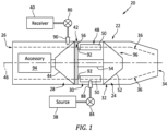
- FIG. 1 illustrates a multi-mode engine system 20.
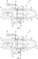
- This engine system 20 is configured with a gas turbine engine 22 during a gas turbine engine mode of operation; e.g., see FIG. 2 .
- the engine system 20 is configured with a turbo-compressor 24 during a turbo-compressor mode of operation; e.g., see FIG. 3 .
- the engine system 20 of FIG. 1 includes an engine inlet 26, a compressor section 28, a combustor section 30, a turbine section 32, an engine exhaust 34 and a (e.g., annular) core flowpath 36 extending sequentially from the engine inlet 26, through the compressor section 28, the combustor section 30 and the turbine section 32, to the engine exhaust 34.
- This engine system 20 also includes a fluid source 38, a fluid receiver 40 and a flow regulator 42.
- the compressor section 28 includes a compressor rotor 44 configured to rotate about a rotational axis 46 of the gas turbine engine 22 / the turbo-compressor 24.
- This compressor rotor 44 includes a plurality of compressor rotor blades arranged circumferentially around and connected to one or more respective compressor rotor disks. The compressor rotor blades are disposed within the core flowpath 36. Each compressor rotor disk is rotatable about the rotational axis 46.
- the compressor section 28 may be configured as an axial flow compressor section.
- the core flowpath 36 of FIG. 1 for example, extends axially along the rotational axis 46 into, within and out of the compressor section 28.
- the compressor section 28 may alternatively be configured as a radial flow compressor section.
- the core flowpath 36 of FIG. 4 for example, extends axially along the rotational axis 46 into the compressor section 28.
- the core flowpath 36 turns radially outward within the compressor section 28.
- the core flowpath 36 extends radially outwards relative to the rotational axis 46 out of the compressor section 28.
- the combustor section 30 of FIG. 1 is fluidly coupled between the compressor section 28 and the turbine section 32.
- the combustor section 30 includes at least one combustor 48 with an internal combustion chamber 50.
- the combustor 48 may be configured as an annular combustor which extends circumferentially around the rotational axis 46.
- the combustor 48 may alternatively be configured as a (e.g., non-annular) CAN-type combustor.
- the combustor 48 may be one of a plurality of combustors 48 within the combustor section 30, and the combustors 48 may be distributed circumferentially about the rotational axis 46.
- the turbine section 32 includes a turbine rotor 52 configured to rotate about the rotational axis 46.
- This turbine rotor 52 includes a plurality of turbine rotor blades arranged circumferentially around and connected to one or more respective turbine rotor disks.
- the turbine rotor blades are disposed within the core flowpath 36.
- Each turbine rotor disk is rotatable about the rotational axis 46.
- the turbine rotor 52 of FIG. 1 is mechanically coupled to the compressor rotor 44 through an engine shaft 54.
- the turbine section 32 may be configured as an axial flow turbine section.
- the core flowpath 36 of FIG. 1 for example, extends axially along the rotational axis 46 into, within and out of the turbine section 32.
- the turbine section 32 may alternatively be configured as a radial flow turbine section.
- the core flowpath 36 of FIG. 4 for example, extends radially inward relative to the rotational axis 46 into the turbine section 32.
- the core flowpath 36 turns axially along the rotational axis 46 within the turbine section 32.
- the core flowpath 36 extends axially along the rotational axis 46 out of the turbine section 32.
- the fluid source 38 is configured to provide fluid source gas to the combustor section 30 and its combustor 48.
- This fluid source gas may be compressed gas and/or high velocity gas.
- the fluid source 38 may be configured as a reservoir such as a bottle, a tank, a cylinder, a bladder or any other type of pressure vessel.
- the reservoir for example, may be configured as an oxygen (O 2 ) bottle.
- the fluid source 38 may alternatively be configured as (or also include) an intake, which may be discrete from the engine inlet 26.
- the intake for example, may be configured as a ram air intake or any other type of forced induction intake.
- the fluid source 38 may still alternatively be configured as (or also include) an internal combustion (IC) engine which is discrete from the gas turbine engine 22.
- IC internal combustion
- This IC engine may be a gas turbine engine, and the fluid source gas may be compressed air bled from a compressor section of that gas turbine engine and/or exhaust gas bled or otherwise received from an exhaust of that gas turbine engine.
- the present disclosure is not limited to the foregoing exemplary fluid source types / configurations.
- the fluid receiver 40 is configured to receive compressed gas bled or otherwise received from the compressor section 28.
- the fluid receiver 40 may be configured as a component of a heat exchanger system; e.g., a heat exchanger.
- the fluid receiver 40 may alternatively be configured as (or also include) a reservoir for containing / storing the compressed gas for later use.
- the fluid receiver 40 may still alternatively be configured as (or also include) an internal combustion (IC) engine which is discrete from the gas turbine engine 22.
- This IC engine may be a gas turbine engine (e.g., a main propulsion system engine), where the compressed gas received from the compressor section 28 may be utilized during, for example, startup of that gas turbine engine.
- the flow regulator 42 is configured to regulate gas (e.g., air) flow through the core flowpath 36 downstream of the compressor section 28 / the compressor rotor 44.
- the flow regulator 42 of FIG. 1 is configured to regulate the gas flow directed through the core flowpath 36 from the compressor section 28 to the combustor 48 and its combustion chamber 50.
- the flow regulator 42 may open (e.g., facilitate flow through) a portion 56 of the core flowpath 36 between the compressor rotor 44 and the combustion chamber 50.
- the flow regulator 42 may thereby fluidly couple the compressor section 28 with the combustor section 30 and its combustion chamber 50.
- the flow regulator 42 may close (e.g., cutoff flow through) the portion 56 of the core flowpath 36 between the compressor rotor 44 and the combustion chamber 50.
- the flow regulator 42 may thereby fluidly decouple the compressor section 28 from the combustor section 30 and its combustion chamber 50.
- the flow regulator 42 may configured as or otherwise include a pivot member 58; e.g., mechanical flap, a door, etc.
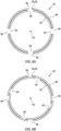
- This pivot member 58 is disposed within the core flowpath 36, and is pivotable about a pivot axis between an open position (see FIG. 7A ) and a closed position (see FIG. 7B ).
- the pivot member 58 In the open position of FIG. 7A , the pivot member 58 may be positioned against a flowpath wall 60 to a side of the core flowpath 36 to facilitate the flow of gas (e.g., compressed air) through the flow regulator 42 and the core flowpath portion 56 during the gas turbine engine mode of operation.
- the pivot member 58 In the closed position of FIG. 7B , the pivot member 58 may extend across and block the core flowpath 36 to cut off the flow of gas (e.g., compressed air) through the flow regulator 42 and the core flowpath portion 56 during the turbo-compressor mode of operation.
- the flow regulator 42 may alternatively be configured as or otherwise include a rotatable member 62; e.g., a rotating cylinder.
- This rotatable member 62 is disposed within the core flowpath 36 (see FIGS. 1 and 4 ), and is rotatable about an axis (e.g., the rotational axis 46) between an open position (see FIG. 8A ) and a closed position (see FIG. 8B ). In the open position of FIG.
- one or more ports 64 in the rotatable member 62 may be respectively aligned with one or more ports 66 in an adjacent (e.g., stationary) member 68 to facilitate the flow of gas (e.g., compressed air) through the flow regulator 42 and the core flowpath portion 56 (see FIGS. 2 and 5 ) during the gas turbine engine mode of operation.
- the ports 64 in the rotatable member 62 may be offset from the ports 66 in the adjacent member 68 and the rotatable member 62 may block the ports 66 in the adjacent member 68 to cut off the flow of gas (e.g., compressed air) through the flow regulator 42 and the core flowpath portion 56 (see FIGS. 3 and 6 ) during the turbo-compressor mode of operation.
- FIGS. 7A-8B illustrate various exemplary embodiments of the flow regulator 42.
- the present disclosure is not limited to such exemplary flow regulator types / configurations.
- the flow regulator 42 may alternatively be configured as or otherwise include various types of valves.
- the flow regulator 42 may also move to one or more intermediate positions during the gas turbine engine mode of operation, the turbo-compressor mode of operation and/or another mode of operation to reduce, but not cutoff, gas flow through the flow regulator 42 / the core flowpath portion 56 to the combustion chamber 50.
- the flow regulator 42 and its moveable member 58, 62 may be hydraulically actuated.
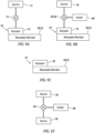
- the flow regulator 42 of FIG. 9A includes a hydraulic actuator 70 (e.g., a hydraulic cylinder) configured to move the moveable member 58, 62 between its open position (e.g., see FIGS. 7A and 8A ) and its closed position (e.g., see FIGS. 7B and 8B ).
- This hydraulic actuator 70 may be fluidly coupled to a hydraulic fluid source 72 (e.g., a pump, etc.) through a control valve 74.
- the flow regulator 42 and its moveable member 58, 62 may alternatively be pneumatically actuated.
- the flow regulator 42 of FIG. 9B includes a pneumatic actuator 76 configured to move the moveable member 58, 62 between its open position (e.g., see FIGS. 7A and 8A ) and its closed position (e.g., see FIGS. 7B and 8B ).
- This pneumatic actuator 76 may be fluidly coupled to a pneumatic fluid source 78 (e.g., a compressor, a pressure vessel, etc.) through a control valve 80.
- the pneumatic fluid source 78 may also be the fluid source 38, or discrete from the fluid source 38.
- the flow regulator 42 and its moveable member 58, 62 may alternatively be electrically actuated.
- the flow regulator 42 of FIG. 9C includes an electric actuator 82 (e.g., an electric step motor) configured to move the moveable member 58, 62 between its open position (e.g., see FIGS. 7A and 8A ) and its closed position (e.g., see FIGS. 7B and 8B ).
- an electric actuator 82 e.g., an electric step motor
- the engine system 20 may include one or more additional flow regulators 84 and 86.
- the fluid source flow regulator 84 e.g., at least one valve
- the fluid source flow regulator 84 is configured to regulate the flow of the fluid source gas from the fluid source 38 to one or more outlets 88 (e.g., injectors) (one visible in FIG. 1 ).
- These outlets 88 of FIG. 1 are configured to direct (e.g., inject) the fluid source gas into the combustor 48 and its the combustion chamber 50 during the gas turbine engine mode of operation, the turbo-compressor mode of operation and/or another mode of operation.
- the fluid source flow regulator 84 may also be configured to select which one or more fluid sources 38 (when multiple are available) to fluidly couple to the outlets 88.
- the fluid receiver flow regulator 86 (e.g., at least one valve) is configured to regulate the flow of the compressed gas from one or more inlets 90 (e.g., bleed ports) (one visible in FIG. 1 ) to the fluid receiver 40.
- These inlets 90 are configured to receive (e.g., bleed and/or redirect) the compressed gas from the compressor section 28 during the gas turbine engine mode of operation, the turbo-compressor mode of operation and/or another mode of operation.
- gas e.g., air
- gas is directed into the core flowpath 36 through the engine inlet 26.
- This gas is compressed within the compressor section 28 by the compressor rotor 44 and directed through the flow regulator 42 into the combustor section 30 and its combustion chamber 50.
- Fuel is injected into the combustion chamber 50 via one or more fuel injectors 92 (see FIGS. 1 and 4 ), where the fuel is mixed with the compressed gas to provide a gas-fuel mixture.
- This gas-fuel mixture is ignited within the combustion chamber 50 by one or more igniters to provide combustion products. These combustion products are directed into the turbine section 32 and cause the turbine rotor 52 to rotate.
- the rotation of the turbine rotor 52 drives rotation of the compressor rotor 44.
- the combustion products are subsequently exhausted from the gas turbine engine 22 through the engine exhaust 34. These exhausted combustion products may provide engine thrust where, for example, the gas turbine engine 22 is configured as part of a propulsion system for an aircraft.
- the exhausted combustion products may alternatively be diffused where, for example, the gas turbine engine 22 is configured as part of a power generation system; e.g., an electrical power generator, a hydraulic power system, etc.
- the fuel flow to the fuel injectors 92 (see FIGS. 1 and 4 ) is turned off.
- the flow regulator 42 is also (subsequently, or simultaneously) moved to its closed position to cutoff the flow of the compressed gas from the compressor section 28 to the combustor 48 and its combustion chamber 50.
- the turbine rotor 52 is thereby no longer rotated by combustion products form the combustion chamber 50.
- the fluid source gas from the fluid source 38 is directed into the flowpath downstream of the closed flow regulator 42 (e.g., within the combustion chamber 50), which fluid source gas flows through the turbine section 32 causing the turbine rotor 52 to rotate.
- the rotation of the of the turbine rotor 52 drives rotation of the compressor rotor 44.
- the rotation of the compressor rotor 44 compresses the gas received from the engine inlet 26 to provide the compressed gas.
- This compressed gas is directed out of the compressor section 28 and the core flowpath 36, upstream of the closed flow regulator 42, to the fluid receiver 40.
- the turbo-compressor 24 is thereby operable to provide (or maintain) the flow of the compressed gas to the fluid receiver 40 even where the combustor section 30 and, thus, the gas turbine engine 22 are non-operational. This may reduce fuel consumption of the engine system 20.
- the flow of the compressed gas provided to the fluid receiver 40 may be directly regulated by adjusting (e.g., metering flow through) the fluid receiver flow regulator 86, and/or indirectly regulated by adjusting (e.g., metering flow through) the fluid source flow regulator 84.
- the compressed gas may also be bled from the compressor section 28 and directed to the fluid receiver 40 during the gas turbine engine mode of operation.
- the fluid source gas may also or alternatively be provided to the combustor section 30 (e.g., directed into the combustion chamber 50) during the gas turbine engine mode of operation. The provision of this fluid source gas may aid in, for example, high altitude startup of the combustor section 30.
- the engine system 20 may include one or more accessories 94 (e.g., shaft mounted accessories) driven by a rotating assembly 96, which rotating assembly 96 may include the compressor rotor 44, the turbine rotor 52 and the engine shaft 54.
- accessories 94 include, but are not limited to, a pump and an electrical generator.
- the rotating assembly 96 may mechanically drive another apparatus discrete from the gas turbine engine 22.
- the gas turbine engine 22 may have various configurations other than the those shown in FIGS. 1-6 .
- the gas turbine engine 22, for example, may be configured as a geared turbine engine where a gear train connects one or more shafts to one or more rotors in a fan section, a compressor section and/or any other engine section.
- the gas turbine engine 22 may be as a direct drive turbine engine configured without a gear train.
- the gas turbine engine 22 may be configured with a single spool (see FIGS. 1-6 ), with two spools, or with more than two spools.
- the gas turbine engine 22 may be configured as a turbofan engine, a turbojet engine, a turboprop engine, a turboshaft engine, a propfan engine, a pusher fan engine or any other type of turbine engine.
- the gas turbine engine 22 may alternatively be configured as an auxiliary power unit (APU) or an industrial gas turbine engine.
- APU auxiliary power unit
Landscapes
- Engineering & Computer Science (AREA)
- Chemical & Material Sciences (AREA)
- Combustion & Propulsion (AREA)
- Mechanical Engineering (AREA)
- General Engineering & Computer Science (AREA)
- Physics & Mathematics (AREA)
- Fluid Mechanics (AREA)
- Chemical Kinetics & Catalysis (AREA)
- General Chemical & Material Sciences (AREA)
- Structures Of Non-Positive Displacement Pumps (AREA)
Abstract
Description
- This disclosure (invention) relates generally to an engine system and, more particularly, to an engine system with a gas turbine engine.
- A gas turbine engine is typically configured for generating thrust and/or power. During operation, the gas turbine engine requires an energy input by way of combusting / burning fuel. By contrast, a turbo-compressor utilizes energy from one gas flow input to compress another gas flow input without requiring an additional energy input. Gas turbine engines and turbo-compressors may be used, but are discrete, in modern engine systems. While these modern engine systems have various benefits, there is still room in the art for improvement.
- According to an aspect of the present invention, an engine system is provided that includes a compressor section, a combustor section, a turbine section, a flowpath and a flow regulator. The combustor section includes a combustion chamber. The flowpath extends sequentially through the compressor section, the combustor section and the turbine section. The flow regulator is configured to open the flowpath between the compressor section and the combustion chamber during a first mode of operation. The flow regulator is configured to close the flowpath between the compressor section and the combustion chamber during a second mode of operation.
- According to another aspect of the present invention, another engine system is provided that includes a compressor section, a combustor section, a turbine section, a gas turbine engine and a turbo-compressor. The compressor section includes a compressor rotor. The turbine section includes a turbine rotor. The gas turbine engine includes the compressor section, the combustor section and the turbine section during a first mode of operation. The combustor section is fluidly coupled with and between the compressor section and the turbine section during the first mode of operation. The turbo-compressor includes the compressor rotor and the turbine rotor during a second mode of operation. The turbine section is fluidly decoupled from the compressor section during the second mode of operation.
- According to another aspect of the present invention, a method is provided for operating an engine system. During this method, compressed gas is directed from a compressor section to a combustor section. Fuel mixed with the compressed gas is ignited within the combustor section to provide combustion products. The combustion products are directed through a turbine section to drive the compressor section. The compressor section is fluidly decoupled from the turbine section. The compressed gas is directed from the compressor section to a fluid receiver. Second gas is directed from a fluid source into the turbine section to drive a compressor rotor in the compressor section.
- The following optional features may be applied to any of the above aspects.
- Optionally, the engine system may also include a flow regulator configured to fluidly couple the compressor section with a combustion chamber within the combustor section during the first mode of operation. The flow regulator may be configured to fluidly decouple the compressor section from the combustion chamber during the second mode of operation.
- Optionally, the compressor section, the combustor section and the turbine section may be configured as a gas turbine engine during the first mode of operation.
- Optionally, during the first mode of operation, the combustor section is configured to: receive compressed gas from the compressor section; ignite a mixture of the compressed gas and fuel within the combustion chamber to provide combustion products; and direct the combustion products into the turbine section.
- Optionally, the compressor section and the turbine section may be configured as a turbo-compressor during the second mode of operation.
- Optionally, the combustor section may be operational during the first mode of operation and the combustor section may be non-operational during the second mode of operation.
- Optionally, the compressor section may include a compressor rotor, the turbine section may include a turbine rotor, and the turbine rotor may be mechanically coupled to the compressor rotor by a shaft.
- Optionally, the engine system may also include a fluid receiver and a fluid source, the fluid receiver may be configured to receive first gas from the compressor section during the second mode of operation, and the fluid source may be configured to direct second gas into the turbine section during the second mode of operation.
- Optionally, the fluid receiver may be configured to receive the first gas from the compressor section during the first mode of operation.
- Optionally, the fluid source may be configured to direct the second gas into the turbine section during the first mode of operation.
- Optionally, the fluid receiver may be configured as or otherwise include a heat exchanger.
- Optionally, the engine system may also include a gas turbine engine which includes the fluid receiver and the gas turbine engine may be discrete from the compressor section, the combustor section and the turbine section.
- Optionally, the fluid receiver may be configured as or otherwise include a reservoir.
- Optionally, the fluid source may be configured as or otherwise include a reservoir.
- Optionally, the fluid source may be configured as or otherwise include a ram air intake.
- Optionally, the engine system may also include a gas turbine engine which includes the fluid source and the gas turbine engine may be discrete from the compressor section, the combustor section and the turbine section.
- Optionally, the compressor section may be configured as or otherwise include an axial flow compressor section and, in addition or alternatively, the turbine section may be configured as or otherwise include an axial flow turbine section.
- Optionally, the compressor section may be configured as or otherwise include a radial flow compressor section and, in addition or alternatively, the turbine section may be configured as or otherwise include a radial flow turbine section.
- The present disclosure may include any one or more of the individual features disclosed above and/or below alone or in any combination thereof.
- The foregoing features and the operation of the invention will become more apparent in light of the following description and the accompanying drawings.
-
-
FIG. 1 is a schematic illustration of a multi-mode engine system configured with an axial flow compressor section and an axial flow turbine section. -
FIG. 2 is a schematic illustration of the engine system ofFIG. 1 during a gas turbine engine mode of operation. -
FIG. 3 is a schematic illustration of the engine system ofFIG. 1 during a turbo-compressor mode of operation. -
FIG. 4 is a schematic illustration of the engine system configured with a radial flow compressor section and a radial flow turbine section. -
FIG. 5 is a schematic illustration of the engine system ofFIG. 4 during a gas turbine engine mode of operation. -
FIG. 6 is a schematic illustration of the engine system ofFIG. 4 during a turbo-compressor mode of operation. -
FIGS. 7A and 7B are illustrations of a flow regulator arranged with a flowpath. -
FIGS. 8A and 8B are illustrations of another flow regulator. -
FIGS. 9A-9C are schematic illustrations of various flow regulator actuation configurations. -
FIG. 10 is a schematic illustration of a fluid source assembly for the engine system. -
FIG. 1 illustrates amulti-mode engine system 20. Thisengine system 20 is configured with agas turbine engine 22 during a gas turbine engine mode of operation; e.g., seeFIG. 2 . Theengine system 20 is configured with a turbo-compressor 24 during a turbo-compressor mode of operation; e.g., seeFIG. 3 . - The
engine system 20 ofFIG. 1 includes anengine inlet 26, acompressor section 28, acombustor section 30, aturbine section 32, anengine exhaust 34 and a (e.g., annular)core flowpath 36 extending sequentially from theengine inlet 26, through thecompressor section 28, thecombustor section 30 and theturbine section 32, to theengine exhaust 34. Thisengine system 20 also includes afluid source 38, afluid receiver 40 and aflow regulator 42. - The
compressor section 28 includes acompressor rotor 44 configured to rotate about arotational axis 46 of thegas turbine engine 22 / the turbo-compressor 24. Thiscompressor rotor 44 includes a plurality of compressor rotor blades arranged circumferentially around and connected to one or more respective compressor rotor disks. The compressor rotor blades are disposed within thecore flowpath 36. Each compressor rotor disk is rotatable about therotational axis 46. - The
compressor section 28 may be configured as an axial flow compressor section. The core flowpath 36 ofFIG. 1 , for example, extends axially along therotational axis 46 into, within and out of thecompressor section 28. Thecompressor section 28 may alternatively be configured as a radial flow compressor section. The core flowpath 36 ofFIG. 4 , for example, extends axially along therotational axis 46 into thecompressor section 28. Thecore flowpath 36 turns radially outward within thecompressor section 28. Thecore flowpath 36 extends radially outwards relative to therotational axis 46 out of thecompressor section 28. - The
combustor section 30 ofFIG. 1 is fluidly coupled between thecompressor section 28 and theturbine section 32. Thecombustor section 30 includes at least onecombustor 48 with aninternal combustion chamber 50. Thecombustor 48 may be configured as an annular combustor which extends circumferentially around therotational axis 46. Thecombustor 48 may alternatively be configured as a (e.g., non-annular) CAN-type combustor. In such embodiments, thecombustor 48 may be one of a plurality ofcombustors 48 within thecombustor section 30, and thecombustors 48 may be distributed circumferentially about therotational axis 46. - The
turbine section 32 includes aturbine rotor 52 configured to rotate about therotational axis 46. Thisturbine rotor 52 includes a plurality of turbine rotor blades arranged circumferentially around and connected to one or more respective turbine rotor disks. The turbine rotor blades are disposed within thecore flowpath 36. Each turbine rotor disk is rotatable about therotational axis 46. Theturbine rotor 52 ofFIG. 1 is mechanically coupled to thecompressor rotor 44 through anengine shaft 54. - The
turbine section 32 may be configured as an axial flow turbine section. The core flowpath 36 ofFIG. 1 , for example, extends axially along therotational axis 46 into, within and out of theturbine section 32. Theturbine section 32 may alternatively be configured as a radial flow turbine section. The core flowpath 36 ofFIG. 4 , for example, extends radially inward relative to therotational axis 46 into theturbine section 32. Thecore flowpath 36 turns axially along therotational axis 46 within theturbine section 32. Thecore flowpath 36 extends axially along therotational axis 46 out of theturbine section 32. - The
fluid source 38 is configured to provide fluid source gas to thecombustor section 30 and itscombustor 48. This fluid source gas may be compressed gas and/or high velocity gas. Thefluid source 38, for example, may be configured as a reservoir such as a bottle, a tank, a cylinder, a bladder or any other type of pressure vessel. The reservoir, for example, may be configured as an oxygen (O2) bottle. Thefluid source 38 may alternatively be configured as (or also include) an intake, which may be discrete from theengine inlet 26. The intake, for example, may be configured as a ram air intake or any other type of forced induction intake. Thefluid source 38 may still alternatively be configured as (or also include) an internal combustion (IC) engine which is discrete from thegas turbine engine 22. This IC engine may be a gas turbine engine, and the fluid source gas may be compressed air bled from a compressor section of that gas turbine engine and/or exhaust gas bled or otherwise received from an exhaust of that gas turbine engine. The present disclosure, however, is not limited to the foregoing exemplary fluid source types / configurations. - The
fluid receiver 40 is configured to receive compressed gas bled or otherwise received from thecompressor section 28. Thefluid receiver 40, for example, may be configured as a component of a heat exchanger system; e.g., a heat exchanger. Thefluid receiver 40 may alternatively be configured as (or also include) a reservoir for containing / storing the compressed gas for later use. Thefluid receiver 40 may still alternatively be configured as (or also include) an internal combustion (IC) engine which is discrete from thegas turbine engine 22. This IC engine may be a gas turbine engine (e.g., a main propulsion system engine), where the compressed gas received from thecompressor section 28 may be utilized during, for example, startup of that gas turbine engine. - The
flow regulator 42 is configured to regulate gas (e.g., air) flow through thecore flowpath 36 downstream of thecompressor section 28 / thecompressor rotor 44. Theflow regulator 42 ofFIG. 1 , for example, is configured to regulate the gas flow directed through the core flowpath 36 from thecompressor section 28 to thecombustor 48 and itscombustion chamber 50. For example, during the gas turbine engine mode of operation ofFIG. 2 (see alsoFIG. 5 ), theflow regulator 42 may open (e.g., facilitate flow through) aportion 56 of thecore flowpath 36 between thecompressor rotor 44 and thecombustion chamber 50. Theflow regulator 42 may thereby fluidly couple thecompressor section 28 with thecombustor section 30 and itscombustion chamber 50. However, during the turbo-compressor mode of operation ofFIG. 3 (see alsoFIG. 6 ), theflow regulator 42 may close (e.g., cutoff flow through) theportion 56 of thecore flowpath 36 between thecompressor rotor 44 and thecombustion chamber 50. Theflow regulator 42 may thereby fluidly decouple thecompressor section 28 from thecombustor section 30 and itscombustion chamber 50. - Referring to
FIGS. 7A and 7B , theflow regulator 42 may configured as or otherwise include apivot member 58; e.g., mechanical flap, a door, etc. Thispivot member 58 is disposed within thecore flowpath 36, and is pivotable about a pivot axis between an open position (seeFIG. 7A ) and a closed position (seeFIG. 7B ). In the open position ofFIG. 7A , thepivot member 58 may be positioned against aflowpath wall 60 to a side of thecore flowpath 36 to facilitate the flow of gas (e.g., compressed air) through theflow regulator 42 and thecore flowpath portion 56 during the gas turbine engine mode of operation. In the closed position ofFIG. 7B , thepivot member 58 may extend across and block thecore flowpath 36 to cut off the flow of gas (e.g., compressed air) through theflow regulator 42 and thecore flowpath portion 56 during the turbo-compressor mode of operation. - Referring to
FIGS. 8A and 8B , theflow regulator 42 may alternatively be configured as or otherwise include arotatable member 62; e.g., a rotating cylinder. Thisrotatable member 62 is disposed within the core flowpath 36 (seeFIGS. 1 and4 ), and is rotatable about an axis (e.g., the rotational axis 46) between an open position (seeFIG. 8A ) and a closed position (seeFIG. 8B ). In the open position ofFIG. 8A , one ormore ports 64 in therotatable member 62 may be respectively aligned with one ormore ports 66 in an adjacent (e.g., stationary)member 68 to facilitate the flow of gas (e.g., compressed air) through theflow regulator 42 and the core flowpath portion 56 (seeFIGS. 2 and5 ) during the gas turbine engine mode of operation. In the closed position ofFIG. 8B , theports 64 in therotatable member 62 may be offset from theports 66 in theadjacent member 68 and therotatable member 62 may block theports 66 in theadjacent member 68 to cut off the flow of gas (e.g., compressed air) through theflow regulator 42 and the core flowpath portion 56 (seeFIGS. 3 and6 ) during the turbo-compressor mode of operation. -
FIGS. 7A-8B illustrate various exemplary embodiments of theflow regulator 42. The present disclosure, however, is not limited to such exemplary flow regulator types / configurations. Theflow regulator 42, for example, may alternatively be configured as or otherwise include various types of valves. Furthermore, while theflow regulator 42 is described above as moving between a (e.g., fully) open position and a (e.g., fully) closed position, it is contemplated theflow regulator 42 may also move to one or more intermediate positions during the gas turbine engine mode of operation, the turbo-compressor mode of operation and/or another mode of operation to reduce, but not cutoff, gas flow through theflow regulator 42 / thecore flowpath portion 56 to thecombustion chamber 50. - Referring to
FIG. 9A , theflow regulator 42 and itsmoveable member 58, 62 (see alsoFIGS. 7A-8B ) may be hydraulically actuated. Theflow regulator 42 ofFIG. 9A , for example, includes a hydraulic actuator 70 (e.g., a hydraulic cylinder) configured to move themoveable member FIGS. 7A and8A ) and its closed position (e.g., seeFIGS. 7B and8B ). Thishydraulic actuator 70 may be fluidly coupled to a hydraulic fluid source 72 (e.g., a pump, etc.) through acontrol valve 74. - Referring to
FIG. 9B , theflow regulator 42 and itsmoveable member 58, 62 (see alsoFIGS. 7A-8B ) may alternatively be pneumatically actuated. Theflow regulator 42 ofFIG. 9B , for example, includes apneumatic actuator 76 configured to move themoveable member FIGS. 7A and8A ) and its closed position (e.g., seeFIGS. 7B and8B ). Thispneumatic actuator 76 may be fluidly coupled to a pneumatic fluid source 78 (e.g., a compressor, a pressure vessel, etc.) through a control valve 80. The pneumaticfluid source 78 may also be thefluid source 38, or discrete from thefluid source 38. - Referring to
FIG. 9C , theflow regulator 42 and itsmoveable member 58, 62 (see alsoFIGS. 7A-8B ) may alternatively be electrically actuated. Theflow regulator 42 ofFIG. 9C , for example, includes an electric actuator 82 (e.g., an electric step motor) configured to move themoveable member FIGS. 7A and8A ) and its closed position (e.g., seeFIGS. 7B and8B ). - Referring to
FIG. 1 , theengine system 20 may include one or moreadditional flow regulators fluid source 38 to one or more outlets 88 (e.g., injectors) (one visible inFIG. 1 ). Theseoutlets 88 ofFIG. 1 are configured to direct (e.g., inject) the fluid source gas into thecombustor 48 and its thecombustion chamber 50 during the gas turbine engine mode of operation, the turbo-compressor mode of operation and/or another mode of operation. In some embodiments, referring toFIG. 10 , the fluidsource flow regulator 84 may also be configured to select which one or more fluid sources 38 (when multiple are available) to fluidly couple to theoutlets 88. - Referring again to
FIG. 1 , the fluid receiver flow regulator 86 (e.g., at least one valve) is configured to regulate the flow of the compressed gas from one or more inlets 90 (e.g., bleed ports) (one visible inFIG. 1 ) to thefluid receiver 40. Theseinlets 90 are configured to receive (e.g., bleed and/or redirect) the compressed gas from thecompressor section 28 during the gas turbine engine mode of operation, the turbo-compressor mode of operation and/or another mode of operation. - During the gas turbine engine mode of operation of
FIG. 2 (see alsoFIG. 5 ), gas (e.g., air) is directed into thecore flowpath 36 through theengine inlet 26. This gas is compressed within thecompressor section 28 by thecompressor rotor 44 and directed through theflow regulator 42 into thecombustor section 30 and itscombustion chamber 50. Fuel is injected into thecombustion chamber 50 via one or more fuel injectors 92 (seeFIGS. 1 and4 ), where the fuel is mixed with the compressed gas to provide a gas-fuel mixture. This gas-fuel mixture is ignited within thecombustion chamber 50 by one or more igniters to provide combustion products. These combustion products are directed into theturbine section 32 and cause theturbine rotor 52 to rotate. The rotation of theturbine rotor 52 drives rotation of thecompressor rotor 44. The combustion products are subsequently exhausted from thegas turbine engine 22 through theengine exhaust 34. These exhausted combustion products may provide engine thrust where, for example, thegas turbine engine 22 is configured as part of a propulsion system for an aircraft. The exhausted combustion products may alternatively be diffused where, for example, thegas turbine engine 22 is configured as part of a power generation system; e.g., an electrical power generator, a hydraulic power system, etc. - During the turbo-compressor mode of operation of
FIG. 3 (see alsoFIG. 6 ), the fuel flow to the fuel injectors 92 (seeFIGS. 1 and4 ) is turned off. Theflow regulator 42 is also (subsequently, or simultaneously) moved to its closed position to cutoff the flow of the compressed gas from thecompressor section 28 to thecombustor 48 and itscombustion chamber 50. Theturbine rotor 52 is thereby no longer rotated by combustion products form thecombustion chamber 50. However, the fluid source gas from thefluid source 38 is directed into the flowpath downstream of the closed flow regulator 42 (e.g., within the combustion chamber 50), which fluid source gas flows through theturbine section 32 causing theturbine rotor 52 to rotate. The rotation of the of theturbine rotor 52 drives rotation of thecompressor rotor 44. The rotation of thecompressor rotor 44 compresses the gas received from theengine inlet 26 to provide the compressed gas. This compressed gas is directed out of thecompressor section 28 and thecore flowpath 36, upstream of theclosed flow regulator 42, to thefluid receiver 40. The turbo-compressor 24 is thereby operable to provide (or maintain) the flow of the compressed gas to thefluid receiver 40 even where thecombustor section 30 and, thus, thegas turbine engine 22 are non-operational. This may reduce fuel consumption of theengine system 20. During the turbo-compressor mode of operation, the flow of the compressed gas provided to thefluid receiver 40 may be directly regulated by adjusting (e.g., metering flow through) the fluidreceiver flow regulator 86, and/or indirectly regulated by adjusting (e.g., metering flow through) the fluidsource flow regulator 84. - In some embodiments, the compressed gas may also be bled from the
compressor section 28 and directed to thefluid receiver 40 during the gas turbine engine mode of operation. The fluid source gas may also or alternatively be provided to the combustor section 30 (e.g., directed into the combustion chamber 50) during the gas turbine engine mode of operation. The provision of this fluid source gas may aid in, for example, high altitude startup of thecombustor section 30. - In some embodiments, referring to
FIGS. 1 and4 , theengine system 20 may include one or more accessories 94 (e.g., shaft mounted accessories) driven by a rotatingassembly 96, which rotatingassembly 96 may include thecompressor rotor 44, theturbine rotor 52 and theengine shaft 54. Examples of theaccessories 94 include, but are not limited to, a pump and an electrical generator. Alternatively, the rotatingassembly 96 may mechanically drive another apparatus discrete from thegas turbine engine 22. - The
gas turbine engine 22 may have various configurations other than the those shown inFIGS. 1-6 . Thegas turbine engine 22, for example, may be configured as a geared turbine engine where a gear train connects one or more shafts to one or more rotors in a fan section, a compressor section and/or any other engine section. Alternatively, thegas turbine engine 22 may be as a direct drive turbine engine configured without a gear train. Thegas turbine engine 22 may be configured with a single spool (seeFIGS. 1-6 ), with two spools, or with more than two spools. Thegas turbine engine 22 may be configured as a turbofan engine, a turbojet engine, a turboprop engine, a turboshaft engine, a propfan engine, a pusher fan engine or any other type of turbine engine. Thegas turbine engine 22 may alternatively be configured as an auxiliary power unit (APU) or an industrial gas turbine engine. - While various embodiments of the present disclosure have been described, it will be apparent to those of ordinary skill in the art that many more embodiments and implementations are possible within the scope of the disclosure. For example, the present disclosure as described herein includes several aspects and embodiments that include particular features. Although these features may be described individually, it is within the scope of the present disclosure that some or all of these features may be combined with any one of the aspects and remain within the scope of the disclosure. Accordingly, the present disclosure is not to be restricted except in light of the attached claims and their equivalents.
Claims (15)
- An engine system (20), comprising:a compressor section (28);a combustor section (30) comprising a combustion chamber (50);a turbine section (32);a flowpath (36) extending sequentially through the compressor section (28), the combustor section (30) and the turbine section (32); anda flow regulator (42) configured to open the flowpath (36) between the compressor section (28) and the combustion chamber (50) during a first mode of operation, the flow regulator (42) configured to close the flowpath (36) between the compressor section (28) and the combustion chamber (50) during a second mode of operation.
- The engine system (20) of claim 1, wherein:the compressor section (28), the combustor section (30) and the turbine section (32) are configured as a gas turbine engine (22) during the first mode of operation; and/orthe compressor section (28) and the turbine section (32) are configured as a turbo-compressor (24) during the second mode of operation.
- The engine system (20) of claim 1 or 2, wherein, during the first mode of operation, the combustor section (30) is configured to:receive compressed gas from the compressor section (28);ignite a mixture of the compressed gas and fuel within the combustion chamber (50) to provide combustion products; anddirect the combustion products into the turbine section (32).
- The engine system (20) of any preceding claim, wherein:the combustor section (30) is operational during the first mode of operation; andthe combustor section (30) is non-operational during the second mode of operation.
- The engine system (20) of any preceding claim, wherein:the compressor section (28) comprises a compressor rotor (44);the turbine section (32) comprises a turbine rotor (52); andthe turbine rotor (52) is mechanically coupled to the compressor rotor (44) by a shaft (54).
- The engine system (20) of any preceding claim, further comprising:a fluid receiver (40) configured to receive first gas from the compressor section (28) during the second mode of operation; anda fluid source (38) configured to direct second gas into the turbine section (32) during the second mode of operation,wherein the fluid receiver (40) optionally comprises a heat exchanger.
- The engine system (20) of claim 6, wherein:the fluid receiver (40) is further configured to receive the first gas from the compressor section (28) during the first mode of operation; and/orthe fluid source (38) is further configured to direct the second gas into the turbine section (32) during the first mode of operation.
- The engine system (20) of claim 6 or 7, further comprising:a gas turbine engine (22) comprising the fluid receiver (40);the gas turbine engine (22) discrete from the compressor section (28), the combustor section (30) and the turbine section (32).
- The engine system (20) of any of claims 6 to 8, wherein:the fluid receiver (40) comprises a reservoir; and/orthe fluid source (38) comprises a reservoir or a ram air intake.
- The engine system (20) of any of claims 6 to 9, further comprising:a gas turbine engine (22) comprising the fluid source (38);the gas turbine engine (22) discrete from the compressor section (28), the combustor section (30) and the turbine section (32).
- The engine system (20) of any preceding claim, wherein:the compressor section (28) comprises an axial flow compressor section (28); and/orthe turbine section (32) comprises an axial flow turbine section (32).
- The engine system (20) of any of claims 1 to 10, wherein:the compressor section (28) comprises a radial flow compressor section (28); and/orthe turbine section (32) comprises a radial flow turbine section (32).
- An engine system (20), comprising:a compressor section (28) comprising a compressor rotor (44);a combustor section (30);a turbine section (32) comprising a turbine rotor (52);a gas turbine engine (22) comprising the compressor section (28), the combustor section (30) and the turbine section (32) during a first mode of operation, the combustor section (30) fluidly coupled with and between the compressor section (28) and the turbine section (32) during the first mode of operation; anda turbo-compressor (24) comprising the compressor rotor (44) and the turbine rotor (52) during a second mode of operation, the turbine section (32) fluidly decoupled from the compressor section (28) during the second mode of operation.
- The engine system (20) of claim 13, further comprising a flow regulator (42) configured to fluidly couple the compressor section (28) with a combustion chamber (50) within the combustor section (30) during the first mode of operation, and the flow regulator (42) configured to fluidly decouple the compressor section (28) from the combustion chamber (50) during the second mode of operation.
- A method for operating an engine system (20), comprising:directing compressed gas from a compressor section (28) to a combustor section (30);igniting fuel mixed with the compressed gas within the combustor section (30) to provide combustion products;directing the combustion products through a turbine section (32) to drive the compressor section (28);fluidly decoupling the compressor section (28) from the turbine section (32);directing the compressed gas from the compressor section (28) to a fluid receiver (40); anddirecting second gas from a fluid source (38) into the turbine section (32) to drive a compressor rotor (44) in the compressor section (28).
Applications Claiming Priority (1)
| Application Number | Priority Date | Filing Date | Title |
|---|---|---|---|
| US17/535,128 US11965458B2 (en) | 2021-11-24 | 2021-11-24 | Multi-mode engine system with gas turbine engine and turbo-compressor |
Publications (1)
| Publication Number | Publication Date |
|---|---|
| EP4187069A1 true EP4187069A1 (en) | 2023-05-31 |
Family
ID=84361538
Family Applications (1)
| Application Number | Title | Priority Date | Filing Date |
|---|---|---|---|
| EP22209437.7A Pending EP4187069A1 (en) | 2021-11-24 | 2022-11-24 | Multi-mode engine system with gas turbine engine and turbo-compressor |
Country Status (2)
| Country | Link |
|---|---|
| US (1) | US11965458B2 (en) |
| EP (1) | EP4187069A1 (en) |
Families Citing this family (1)
| Publication number | Priority date | Publication date | Assignee | Title |
|---|---|---|---|---|
| US12110116B1 (en) * | 2023-06-30 | 2024-10-08 | Rtx Corporation | Pre-heating aircraft engine in standby mode |
Citations (3)
| Publication number | Priority date | Publication date | Assignee | Title |
|---|---|---|---|---|
| US4215550A (en) * | 1977-02-17 | 1980-08-05 | Motoren- Und Turbinen-Union Friedrichshafen Gmbh | Supercharged internal combustion engine and method of operation thereof |
| US5018354A (en) * | 1987-07-23 | 1991-05-28 | Etat Francais, Represente Par Le Delegue General Pour L'armament | Auxiliary combustion chambers for supercharged internal combustion engines and internal combustion engines equipped with such a chamber |
| US20190284949A1 (en) * | 2016-06-30 | 2019-09-19 | Ge Global Sourcing Llc | Method and systems for an energy recovery and energy converting unit for an engine |
Family Cites Families (4)
| Publication number | Priority date | Publication date | Assignee | Title |
|---|---|---|---|---|
| US2460523A (en) | 1945-12-20 | 1949-02-01 | Svenska Turbinfab Ab | Combined gas turbocompressor and gas turbine |
| US2787886A (en) * | 1951-11-17 | 1957-04-09 | Garrett Corp | Aircraft auxiliary power device using compounded gas turbo-compressor units |
| AU2002951703A0 (en) * | 2002-09-27 | 2002-10-17 | Commonwealth Scientific And Industrial Research Organisation | A method and system for a combustion of methane |
| US20120138737A1 (en) * | 2010-12-02 | 2012-06-07 | Bruno Louis J | Aircraft power distribution architecture |
-
2021
- 2021-11-24 US US17/535,128 patent/US11965458B2/en active Active
-
2022
- 2022-11-24 EP EP22209437.7A patent/EP4187069A1/en active Pending
Patent Citations (3)
| Publication number | Priority date | Publication date | Assignee | Title |
|---|---|---|---|---|
| US4215550A (en) * | 1977-02-17 | 1980-08-05 | Motoren- Und Turbinen-Union Friedrichshafen Gmbh | Supercharged internal combustion engine and method of operation thereof |
| US5018354A (en) * | 1987-07-23 | 1991-05-28 | Etat Francais, Represente Par Le Delegue General Pour L'armament | Auxiliary combustion chambers for supercharged internal combustion engines and internal combustion engines equipped with such a chamber |
| US20190284949A1 (en) * | 2016-06-30 | 2019-09-19 | Ge Global Sourcing Llc | Method and systems for an energy recovery and energy converting unit for an engine |
Also Published As
| Publication number | Publication date |
|---|---|
| US20230160339A1 (en) | 2023-05-25 |
| US11965458B2 (en) | 2024-04-23 |
Similar Documents
| Publication | Publication Date | Title |
|---|---|---|
| US11168616B2 (en) | Hybrid electric fan with improved low pressure compressor | |
| EP3693572B1 (en) | Power assisted engine start bleed system | |
| EP2472081B1 (en) | Variable cycle gas turbine engine | |
| US20240417101A1 (en) | Gas turbine engine with clutch assembly | |
| US20220074349A1 (en) | Split compressor gas turbine engine | |
| CN116464561B (en) | Pressurized airflow to rotary compressor during engine shutdown | |
| CN108137162A (en) | Auxiliary power unit with variable gear ratio | |
| US9297304B2 (en) | Gas turbine engine system with bleed air powered auxiliary engine | |
| US11008949B2 (en) | Multi-source air system and switching valve assembly for a gas turbine engine | |
| US20200386405A1 (en) | Aircraft engine and method of operating same | |
| EP4187069A1 (en) | Multi-mode engine system with gas turbine engine and turbo-compressor | |
| EP3739191B1 (en) | Variable area turbine nozzle and method | |
| EP4484728A1 (en) | Aircraft powerplant with multiple independent fuel systems | |
| EP4365426A1 (en) | Powerplant with multiple integrated gas turbine engines | |
| US12163465B1 (en) | Turbine engine with couplable rotating assemblies | |
| US12552545B1 (en) | Drivetrain for aircraft powerplant with boosted turbine engine | |
| US12345165B1 (en) | Gas turbine engine having multiple steam turbines | |
| US12416409B2 (en) | Gas turbine engine having a combustion section with steam provided to second combustor plenum | |
| US20260085634A1 (en) | Gas turbine engine system with fuel driven turbine | |
| EP4726189A1 (en) | Aircraft powerplant with boosted turbine engine and fuel cell system |
Legal Events
| Date | Code | Title | Description |
|---|---|---|---|
| PUAI | Public reference made under article 153(3) epc to a published international application that has entered the european phase |
Free format text: ORIGINAL CODE: 0009012 |
|
| STAA | Information on the status of an ep patent application or granted ep patent |
Free format text: STATUS: THE APPLICATION HAS BEEN PUBLISHED |
|
| AK | Designated contracting states |
Kind code of ref document: A1 Designated state(s): AL AT BE BG CH CY CZ DE DK EE ES FI FR GB GR HR HU IE IS IT LI LT LU LV MC ME MK MT NL NO PL PT RO RS SE SI SK SM TR |
|
| RAP3 | Party data changed (applicant data changed or rights of an application transferred) |
Owner name: RTX CORPORATION |
|
| STAA | Information on the status of an ep patent application or granted ep patent |
Free format text: STATUS: REQUEST FOR EXAMINATION WAS MADE |
|
| 17P | Request for examination filed |
Effective date: 20231130 |
|
| RBV | Designated contracting states (corrected) |
Designated state(s): AL AT BE BG CH CY CZ DE DK EE ES FI FR GB GR HR HU IE IS IT LI LT LU LV MC ME MK MT NL NO PL PT RO RS SE SI SK SM TR |
|
| STAA | Information on the status of an ep patent application or granted ep patent |
Free format text: STATUS: EXAMINATION IS IN PROGRESS |
|
| 17Q | First examination report despatched |
Effective date: 20250402 |