EP4187027A1 - Method and control system of a hydraulic circuit of a work vehicle - Google Patents
Method and control system of a hydraulic circuit of a work vehicle Download PDFInfo
- Publication number
- EP4187027A1 EP4187027A1 EP22210368.1A EP22210368A EP4187027A1 EP 4187027 A1 EP4187027 A1 EP 4187027A1 EP 22210368 A EP22210368 A EP 22210368A EP 4187027 A1 EP4187027 A1 EP 4187027A1
- Authority
- EP
- European Patent Office
- Prior art keywords
- hydraulic
- control
- control levers
- electric motor
- deflection
- Prior art date
- Legal status (The legal status is an assumption and is not a legal conclusion. Google has not performed a legal analysis and makes no representation as to the accuracy of the status listed.)
- Granted
Links
Images

Classifications
-
- E—FIXED CONSTRUCTIONS
- E02—HYDRAULIC ENGINEERING; FOUNDATIONS; SOIL SHIFTING
- E02F—DREDGING; SOIL-SHIFTING
- E02F9/00—Component parts of dredgers or soil-shifting machines, not restricted to one of the kinds covered by groups E02F3/00 - E02F7/00
- E02F9/20—Drives; Control devices
- E02F9/22—Hydraulic or pneumatic drives
- E02F9/2221—Control of flow rate; Load sensing arrangements
- E02F9/2225—Control of flow rate; Load sensing arrangements using pressure-compensating valves
- E02F9/2228—Control of flow rate; Load sensing arrangements using pressure-compensating valves including an electronic controller
-
- E—FIXED CONSTRUCTIONS
- E02—HYDRAULIC ENGINEERING; FOUNDATIONS; SOIL SHIFTING
- E02F—DREDGING; SOIL-SHIFTING
- E02F9/00—Component parts of dredgers or soil-shifting machines, not restricted to one of the kinds covered by groups E02F3/00 - E02F7/00
- E02F9/20—Drives; Control devices
- E02F9/2058—Electric or electro-mechanical or mechanical control devices of vehicle sub-units
- E02F9/2062—Control of propulsion units
- E02F9/2075—Control of propulsion units of the hybrid type
-
- F—MECHANICAL ENGINEERING; LIGHTING; HEATING; WEAPONS; BLASTING
- F15—FLUID-PRESSURE ACTUATORS; HYDRAULICS OR PNEUMATICS IN GENERAL
- F15B—SYSTEMS ACTING BY MEANS OF FLUIDS IN GENERAL; FLUID-PRESSURE ACTUATORS, e.g. SERVOMOTORS; DETAILS OF FLUID-PRESSURE SYSTEMS, NOT OTHERWISE PROVIDED FOR
- F15B2211/00—Circuits for servomotor systems
- F15B2211/20—Fluid pressure source, e.g. accumulator or variable axial piston pump
- F15B2211/205—Systems with pumps
- F15B2211/20507—Type of prime mover
- F15B2211/20515—Electric motor
-
- F—MECHANICAL ENGINEERING; LIGHTING; HEATING; WEAPONS; BLASTING
- F15—FLUID-PRESSURE ACTUATORS; HYDRAULICS OR PNEUMATICS IN GENERAL
- F15B—SYSTEMS ACTING BY MEANS OF FLUIDS IN GENERAL; FLUID-PRESSURE ACTUATORS, e.g. SERVOMOTORS; DETAILS OF FLUID-PRESSURE SYSTEMS, NOT OTHERWISE PROVIDED FOR
- F15B2211/00—Circuits for servomotor systems
- F15B2211/20—Fluid pressure source, e.g. accumulator or variable axial piston pump
- F15B2211/205—Systems with pumps
- F15B2211/2053—Type of pump
- F15B2211/20538—Type of pump constant capacity
-
- F—MECHANICAL ENGINEERING; LIGHTING; HEATING; WEAPONS; BLASTING
- F15—FLUID-PRESSURE ACTUATORS; HYDRAULICS OR PNEUMATICS IN GENERAL
- F15B—SYSTEMS ACTING BY MEANS OF FLUIDS IN GENERAL; FLUID-PRESSURE ACTUATORS, e.g. SERVOMOTORS; DETAILS OF FLUID-PRESSURE SYSTEMS, NOT OTHERWISE PROVIDED FOR
- F15B2211/00—Circuits for servomotor systems
- F15B2211/30—Directional control
- F15B2211/31—Directional control characterised by the positions of the valve element
- F15B2211/3105—Neutral or centre positions
- F15B2211/3116—Neutral or centre positions the pump port being open in the centre position, e.g. so-called open centre
-
- F—MECHANICAL ENGINEERING; LIGHTING; HEATING; WEAPONS; BLASTING
- F15—FLUID-PRESSURE ACTUATORS; HYDRAULICS OR PNEUMATICS IN GENERAL
- F15B—SYSTEMS ACTING BY MEANS OF FLUIDS IN GENERAL; FLUID-PRESSURE ACTUATORS, e.g. SERVOMOTORS; DETAILS OF FLUID-PRESSURE SYSTEMS, NOT OTHERWISE PROVIDED FOR
- F15B2211/00—Circuits for servomotor systems
- F15B2211/30—Directional control
- F15B2211/32—Directional control characterised by the type of actuation
- F15B2211/327—Directional control characterised by the type of actuation electrically or electronically
-
- F—MECHANICAL ENGINEERING; LIGHTING; HEATING; WEAPONS; BLASTING
- F15—FLUID-PRESSURE ACTUATORS; HYDRAULICS OR PNEUMATICS IN GENERAL
- F15B—SYSTEMS ACTING BY MEANS OF FLUIDS IN GENERAL; FLUID-PRESSURE ACTUATORS, e.g. SERVOMOTORS; DETAILS OF FLUID-PRESSURE SYSTEMS, NOT OTHERWISE PROVIDED FOR
- F15B2211/00—Circuits for servomotor systems
- F15B2211/60—Circuit components or control therefor
- F15B2211/63—Electronic controllers
- F15B2211/6303—Electronic controllers using input signals
- F15B2211/6346—Electronic controllers using input signals representing a state of input means, e.g. joystick position
-
- F—MECHANICAL ENGINEERING; LIGHTING; HEATING; WEAPONS; BLASTING
- F15—FLUID-PRESSURE ACTUATORS; HYDRAULICS OR PNEUMATICS IN GENERAL
- F15B—SYSTEMS ACTING BY MEANS OF FLUIDS IN GENERAL; FLUID-PRESSURE ACTUATORS, e.g. SERVOMOTORS; DETAILS OF FLUID-PRESSURE SYSTEMS, NOT OTHERWISE PROVIDED FOR
- F15B2211/00—Circuits for servomotor systems
- F15B2211/60—Circuit components or control therefor
- F15B2211/665—Methods of control using electronic components
- F15B2211/6651—Control of the prime mover, e.g. control of the output torque or rotational speed
Definitions
- the present invention relates to the field of methods and control systems for hydraulic circuits of work vehicles and in particular of electrified work vehicles, in which the hydraulic circuit is powered exclusively by an electro-pump.
- the organs or members such as arms and related tools, is carried out by means of a hydraulic circuit.
- the hydraulic circuit is powered by a hydraulic pump driven in rotation by a prime mover, very often an internal combustion engine.
- a hydraulic pump driven in rotation by a prime mover very often an internal combustion engine.
- the progressive technological development of battery power systems makes it possible to design work vehicles with electric propulsion and/or with a hydraulic system powered by an electric motor that drives a hydraulic pump in rotation, such as an actuation hydraulic circuit for at least one hydraulic actuator enslaved to the movement of a hydraulic work member.
- work hydraulic member it is meant one of those components such as arms, buckets, etc .. distinct and separate from those inherent to the propulsion of the work vehicle, such as for example transmissions, braking systems, etc.
- hydroaulic member meaning a “work hydraulic member”.
- the lifting and lowering of the arm, as well as the opening and closing of the bucket or forks, are carried out using at least one double-acting linear hydraulic actuator. It includes a pair of opposing chambers that are filled and emptied alternately to raise or lower the arm.
- valves for controlling hydraulic actuators There are different types of valves for controlling hydraulic actuators. The most implemented are the open center directional valves. These valves, in relation to the position of the relative movable spool, divide the hydraulic oil fluid pumped by the hydraulic pump into a first flow destined for one of the hydraulic actuator chambers, while the second and remaining flow, is sent to a collecting tank, from where the hydraulic pump draws on the the hydraulic oil to recirculate it.
- the position of the movable spool is generally controlled by the operator using a joystick placed in the vehicle's cockpit.
- the electrical signal generated by the joystick is acquired by a processing unit, which processes it to proportionally control the directional control valve.
- a processing unit which processes it to proportionally control the directional control valve.
- the greater the deflection of the control lever the greater the oil sent to the corresponding hydraulic actuator.
- the directional control valve is evidently of the electro-hydraulic type.
- the rotation speed of the electric motor enslaved to the hydraulic circuit for supplying the work members can be controlled independently from other subsystems.
- the rotation speed of the hydraulic pumps depends on the rotation speed of the internal combustion engine, in electrified vehicles this dependency is lacking.
- the present applicant in a non-disclosed prototype, has implemented a control strategy of the electric motor, according to which the rotation speed is controlled so as to be proportional to the sum of the deflections of the control levers of the different hydraulic actuators.
- the behavior of the hydraulic members was found to be different from that expected and sometimes difficult to control.
- the fact of controlling the rotation speed of the electric motor proportionally to the activation of the hydraulic members is essential to minimize the consumption of electricity in order to extend the activity time of the electrified work vehicle.
- the purpose of the present invention is to improve the responsiveness of the working parts.
- control of the electric motor that drives the hydraulic pump that feeds the control circuit of the work members is proportional to the sum of the deflections of the control levers of the hydraulic members.
- the basic idea of the present invention is to generate a hydraulic flow proportional to the sum of the control signals generated by the control levers that can be operated by the operator, to calculate a nominal opening degree of each directional valve as a function of the corresponding control signal generated by the corresponding control lever and to correct the opening control signal of each control valve according to a valve opening reduction table, which takes into account the simultaneous activation of all the directional valves of the hydraulic circuit.
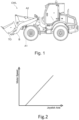
- Figure 1 shows an example of a work machine CWL equipped with hydraulic work members B, TO and in particular an arm B and a bucket TO.
- the arm is operated by a per se known double action hydraulic actuator A1.
- the bucket is operated by a per se known double action hydraulic actuator A2.
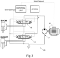
- Both actuators are powered by the same hydraulic circuit HB, see figure 3 , equipped with a hydraulic pump P operatively connected to an electric motor M to be driven in rotation exclusively by it.
- the electric motor is powered by a source of electrical energy.
- Figure 2 shows a diagram that relates to a deflection of the "Joystick Axis" control lever of one of the actuators and the rotation speed of the "Motor Speed” electric motor, when only one actuator is activated at a time.
- the opening degree of the relative directional valve follows another control strategy, for example, it can be decided to leads to the maximum opening degree, by adjusting the oil flow on the basis of the electric motor control.
- the control lever is indicated in figure 3 as "JOYSTICK”.
- a joystick is generally used to control the arm and the bucket as it can be operated along two mutually perpendicular axes.
- control lever or “command lever”
- command lever the man-machine interfaces for the control of hydraulic work components can have any nature and shape.
- the rotation speed of the electric motor is equal to the sum of the speeds, each calculated as a function of the deflection of the corresponding control lever available to the operator.
- the joystick lever can be tilted in two directions perpendicular to each other, it is suitable for controlling the arm in a first Y direction and the bucket in a second X direction perpendicular to the first.
- each BOOM and BUCKET actuator is powered by means of an open center directional solenoid valve V1 and V2, respectively.
- the processing unit CONTROL UNIT is arranged to acquire the signals, generated by the control levers, representative of the relative deflections and to control the electric motor M which drives the hydraulic pump P in rotation and to control the degree or, equivalently, the position of the movable spool inside each directional valve.
- the processing unit According to the acquired signals, the processing unit generates the control signals of the valves V1 and V2 and the control signal of the electric motor M.
- the processing unit when the processing unit detects that two or more control levers are controlled simultaneously, it performs the following steps:
- the following table shows an example of application of the reduction in the degree of opening of the valves which respectively supply the two actuators BOOM and BUCKET which control respectively the position of the arm B with respect to the vehicle frame and of the bucket TO with respect to the arm.
- the first line indicates a percentage deflection value "Boom Command%" with respect to the maximum deflection of the control lever in the direction Y > 0 which controls the "Lowering" of boom B: 0, 20, 40, 60, 80, 100 %.
- the first column indicates a percentage value of deflection "Bucket Command%" with respect to the maximum deflection of the control lever in the direction X > 0 which controls the "Rollback" recall of the bucket TO: 0, 20, 40, 60, 80, 100%. Since the hydraulic load to recall the "Load on Bucket Rollback" is greater than the hydraulic load to lower the "Load on Boom Lowering” arm, when these two movements are activated at the same time, only the degree of opening of the valve V1 which supplies the "lowering of the boom” to a percentage value "Boom Command Derating%" such as to have about the same hydraulic load on the lowering of the boom compared to the rollback of the bucket.
- the hydraulic load is the pressure perceived by each valve immediately upstream of the relative movable spool.
- upstream takes into account the direction of circulation of the hydraulic oil.
- the opening degree of the valve V1 is reduced by 62% from the nominal opening degree when the control lever of the valve V2 is activated to rollback the bucket, regardless of its deflection degree.
- the present invention it is possible not only to compensate the increase in flow rate due to the summative control of the rotation speed of the electric motor but it is also possible to differentiate the response of the individual actuators when two or more of them are activated simultaneously so that the relative behaviour remains similar to the case in which they are activated individually.
- Each hydraulic component can move in two opposite directions, for example the arm can raise Y ⁇ 0 and lower Y > 0, while the bucket can be retracted X > 0, i.e. rotate backwards (load or rollback), or can be overturned X ⁇ 0, or rotate forward (discharge).
- the present invention can also be applied to solutions, which provide for the concomitant activation of three or more hydraulic actuators. It is clear that in this case, the reduction table has a dimensionality equal to the number of hydraulic actuators.
- the processing unit is configured to perform the following steps in succession:
- step ii can be simultaneous to the setting of the outflow section of the directional valves, step iv.
- step ii and steps iii and iv can be performed in parallel by means of two parallel "tasks".
- the present invention can be advantageously carried out by means of a computer program, which comprises coding means for carrying out one or more steps of the method, when this program is executed on a computer. Therefore, it is intended that the scope of protection extends to said computer program and further to computer readable means comprising a recorded message, said computer readable means comprising program coding means for carrying out one or more steps of the method, when said program is run on a computer. Implementation variants of the described non-limiting example are possible, without however departing from the scope of protection of the present invention, including all the equivalent embodiments for a person skilled in the art, to the content of the claims.
Landscapes
- Engineering & Computer Science (AREA)
- Mining & Mineral Resources (AREA)
- Civil Engineering (AREA)
- General Engineering & Computer Science (AREA)
- Structural Engineering (AREA)
- Physics & Mathematics (AREA)
- Fluid Mechanics (AREA)
- Operation Control Of Excavators (AREA)
- Fluid-Pressure Circuits (AREA)
Abstract
Description
- The present invention relates to the field of methods and control systems for hydraulic circuits of work vehicles and in particular of electrified work vehicles, in which the hydraulic circuit is powered exclusively by an electro-pump.
- In the field of work and agricultural vehicles, the organs or members, such as arms and related tools, is carried out by means of a hydraulic circuit.
- The hydraulic circuit is powered by a hydraulic pump driven in rotation by a prime mover, very often an internal combustion engine. However, the progressive technological development of battery power systems makes it possible to design work vehicles with electric propulsion and/or with a hydraulic system powered by an electric motor that drives a hydraulic pump in rotation, such as an actuation hydraulic circuit for at least one hydraulic actuator enslaved to the movement of a hydraulic work member.
- By "work hydraulic member" it is meant one of those components such as arms, buckets, etc .. distinct and separate from those inherent to the propulsion of the work vehicle, such as for example transmissions, braking systems, etc. Hereinafter, for convenience, reference is made to a "hydraulic member" meaning a "work hydraulic member".
- In work machines, the most well known and implemented members are the arms equipped with bucket or forks or other devices.
- The lifting and lowering of the arm, as well as the opening and closing of the bucket or forks, are carried out using at least one double-acting linear hydraulic actuator. It includes a pair of opposing chambers that are filled and emptied alternately to raise or lower the arm.
- There are different types of valves for controlling hydraulic actuators. The most implemented are the open center directional valves. These valves, in relation to the position of the relative movable spool, divide the hydraulic oil fluid pumped by the hydraulic pump into a first flow destined for one of the hydraulic actuator chambers, while the second and remaining flow, is sent to a collecting tank, from where the hydraulic pump draws on the the hydraulic oil to recirculate it.
- In particular, when the spool is in the rest (or released) position, all the pumped flow from the pump is sent to the tank; during the adjustment phase, the flow of the hydraulic pump is divided between the actuator and the tank. When the spool is in the maximum opening position, all the pump flow is sent to the actuator.
- The position of the movable spool is generally controlled by the operator using a joystick placed in the vehicle's cockpit.
- The electrical signal generated by the joystick is acquired by a processing unit, which processes it to proportionally control the directional control valve. In other words, the greater the deflection of the control lever, the greater the oil sent to the corresponding hydraulic actuator. The directional control valve is evidently of the electro-hydraulic type.
- When two or more hydraulic members are activated simultaneously, the flow of oil generated by the hydraulic pump is divided between the corresponding two or more actuators and the recovery tank. In addition, the oil flow, with the same opening of the mobile spool, will be greater towards the actuator which has the lowest hydraulic load.
- In electrified vehicles, the rotation speed of the electric motor enslaved to the hydraulic circuit for supplying the work members can be controlled independently from other subsystems. In fact, while, in vehicles equipped with an internal combustion engine, the rotation speed of the hydraulic pumps depends on the rotation speed of the internal combustion engine, in electrified vehicles this dependency is lacking.
- The present applicant, in a non-disclosed prototype, has implemented a control strategy of the electric motor, according to which the rotation speed is controlled so as to be proportional to the sum of the deflections of the control levers of the different hydraulic actuators. However, the behavior of the hydraulic members was found to be different from that expected and sometimes difficult to control. However, the fact of controlling the rotation speed of the electric motor proportionally to the activation of the hydraulic members is essential to minimize the consumption of electricity in order to extend the activity time of the electrified work vehicle.
- It is evident that it is indifferent to talk about the sum of the deflections, obviously calculated with respect to a release position of the same levers, or to talk about the opening degree of the corresponding valves or the degree of activation of the same hydraulic organs.
- If not specifically excluded in the detailed description that follows, what is described in this chapter is to be considered as an integral part of the detailed description.
- The purpose of the present invention is to improve the responsiveness of the working parts. In particular, when the control of the electric motor that drives the hydraulic pump that feeds the control circuit of the work members is proportional to the sum of the deflections of the control levers of the hydraulic members.
- The basic idea of the present invention is to generate a hydraulic flow proportional to the sum of the control signals generated by the control levers that can be operated by the operator, to calculate a nominal opening degree of each directional valve as a function of the corresponding control signal generated by the corresponding control lever and to correct the opening control signal of each control valve according to a valve opening reduction table, which takes into account the simultaneous activation of all the directional valves of the hydraulic circuit.
- Thanks to this limitation table, there is such a behaviour that the behaviour of the hydraulic members is the desired one.
- Further objects and advantages of the present invention will become clear from the following detailed description of an example of its embodiment (and its variants) and from the attached drawings given purely by way of non-limiting explanation, in which:
-
Figure 1 shows a work machine and in particular a mechanical shovel comprising two or more hydraulic work members; -
Figure 2 shows a control diagram of the rotation speed of the electric pump, which feeds the hydraulic circuit of the work machine infigure 1 , as a function of the deflection of a single control lever of a hydraulic actuator; -
Figure 3 shows an example of a hydraulic control circuit of two hydraulic actuators enslaved to the control of an arm of the work machine ofFigure 1 ; -
Figure 4 shows a control flow diagram of two hydraulic members activated at the same time. - The same reference numbers and letters in the figures identify the same elements or components or functions.
- It should also be noted that the terms "first", "second", "third", "upper", "lower" and the like can be used here to distinguish various elements. These terms do not imply a spatial, sequential or hierarchical order for the modified elements unless specifically indicated or inferred from the text.
- The elements and features illustrated in the various preferred embodiments, including the drawings, can be combined with each other without however departing from the scope of this application as described below.
-
Figure 1 shows an example of a work machine CWL equipped with hydraulic work members B, TO and in particular an arm B and a bucket TO. - The arm is operated by a per se known double action hydraulic actuator A1.
- The bucket is operated by a per se known double action hydraulic actuator A2.
- Both actuators are powered by the same hydraulic circuit HB, see
figure 3 , equipped with a hydraulic pump P operatively connected to an electric motor M to be driven in rotation exclusively by it. - The electric motor is powered by a source of electrical energy.
-
Figure 2 shows a diagram that relates to a deflection of the "Joystick Axis" control lever of one of the actuators and the rotation speed of the "Motor Speed" electric motor, when only one actuator is activated at a time. - It is noted that the trend is linear with an intersection with the abscissa axis as a so-called guard band is expected, within which the deflection of the control lever is neglected.
- Furthermore, when only one actuator is activated, the opening degree of the relative directional valve follows another control strategy, for example, it can be decided to leads to the maximum opening degree, by adjusting the oil flow on the basis of the electric motor control.
- The control lever is indicated in
figure 3 as "JOYSTICK". - A joystick is generally used to control the arm and the bucket as it can be operated along two mutually perpendicular axes.
- In the following, reference will be made to a "control lever" or "command lever", bearing in mind that the man-machine interfaces for the control of hydraulic work components can have any nature and shape.
- According to a first aspect of the present invention, the rotation speed of the electric motor is equal to the sum of the speeds, each calculated as a function of the deflection of the corresponding control lever available to the operator.
- Since the joystick lever can be tilted in two directions perpendicular to each other, it is suitable for controlling the arm in a first Y direction and the bucket in a second X direction perpendicular to the first.
- With reference to
Figure 3 , it can be seen that each BOOM and BUCKET actuator is powered by means of an open center directional solenoid valve V1 and V2, respectively. - As described above, when the movable spool of each valve is in the adjustment position, a first portion of the flow is sent to the actuator, while a second portion is sent to the recovery tank T, from which the hydraulic pump P draws. According to the present invention, the processing unit CONTROL UNIT is arranged to acquire the signals, generated by the control levers, representative of the relative deflections and to control the electric motor M which drives the hydraulic pump P in rotation and to control the degree or, equivalently, the position of the movable spool inside each directional valve.
- According to the acquired signals, the processing unit generates the control signals of the valves V1 and V2 and the control signal of the electric motor M.
- According to the present invention, when the processing unit detects that two or more control levers are controlled simultaneously, it performs the following steps:
- Controlling of the electric motor so as to reach a rotation speed proportional to the sum of the deflection values of the two or more control levers,
- Calculation of a degree of opening of each directional valve proportional to the deflection of the corresponding control lever,
- Reduction of the opening degree of each valve according to the deflection value of all the control levers.
- The following table shows an example of application of the reduction in the degree of opening of the valves which respectively supply the two actuators BOOM and BUCKET which control respectively the position of the arm B with respect to the vehicle frame and of the bucket TO with respect to the arm.
0 20 40 60 80 100 Boom Command % Lowering (Y>0) 0 0 0 0 0 0 0 Boom Command Derating* % 20 0 50 58 62 63 64 40 0 50 58 62 63 64 60 0 50 58 62 63 64 80 0 50 58 62 63 64 100 0 50 58 62 63 64 Bucket Command % Rollback (x>0) * Load on Bucket Rollback > Load on Boom Lowering - The first line indicates a percentage deflection value "Boom Command%" with respect to the maximum deflection of the control lever in the direction Y > 0 which controls the "Lowering" of boom B: 0, 20, 40, 60, 80, 100 %.
- The first column indicates a percentage value of deflection "Bucket Command%" with respect to the maximum deflection of the control lever in the direction X > 0 which controls the "Rollback" recall of the bucket TO: 0, 20, 40, 60, 80, 100%. Since the hydraulic load to recall the "Load on Bucket Rollback" is greater than the hydraulic load to lower the "Load on Boom Lowering" arm, when these two movements are activated at the same time, only the degree of opening of the valve V1 which supplies the "lowering of the boom" to a percentage value "Boom Command Derating%" such as to have about the same hydraulic load on the lowering of the boom compared to the rollback of the bucket.
- The hydraulic load, as known, is the pressure perceived by each valve immediately upstream of the relative movable spool. In which "upstream" takes into account the direction of circulation of the hydraulic oil.
- For example, when the nominal signal for controlling the lowering of the arm is equal to 60% of the maximum signal, then there is an attenuation of this signal equal to 62%, so that the signal actually used to control the relative valve V1 is equal to 60 % * 0.62 = 37.2% for each value of the nominal bucket rollback control signal (20, 40, 60, 80, 100%) .
- In other words, the opening degree of the valve V1 is reduced by 62% from the nominal opening degree when the control lever of the valve V2 is activated to rollback the bucket, regardless of its deflection degree.
- Therefore, thanks to the present invention it is possible not only to compensate the increase in flow rate due to the summative control of the rotation speed of the electric motor but it is also possible to differentiate the response of the individual actuators when two or more of them are activated simultaneously so that the relative behaviour remains similar to the case in which they are activated individually.
- Each hydraulic component can move in two opposite directions, for example the arm can raise Y < 0 and lower Y > 0, while the bucket can be retracted X > 0, i.e. rotate backwards (load or rollback), or can be overturned X < 0, or rotate forward (discharge).
- Four combinations are therefore identified. For each of these combinations, a table for reducing the degree of opening of the directional valves can be provided.
- It is worth highlighting that the present invention can also be applied to solutions, which provide for the concomitant activation of three or more hydraulic actuators. It is clear that in this case, the reduction table has a dimensionality equal to the number of hydraulic actuators.
- According to the present invention, the processing unit is configured to perform the following steps in succession:
- (Step i) Acquisition of an electrical signal representative of a deflection of each of said two or more control levers, and then
- (Step ii) Calculation of a rotation speed of the electric motor proportional to a sum of the deflections of the two or more control levers, and
- (Step iii) calculation, for each of said two or more directional valves (V1, V2), of a valve opening value as a function of
- + a value of the corresponding deflection and
- + values of the deflections of the remaining one or more control levers, in order to obtain a common hydraulic load on all active valves, and subsequently
- (Step iv) setting of said calculated opening value.
- While it is clear that the first acquisition step must precede all the other steps, the setting of the rotation speed of the electric motor, step ii, can be simultaneous to the setting of the outflow section of the directional valves, step iv.
- In other words, step ii and steps iii and iv can be performed in parallel by means of two parallel "tasks".
- The present invention can be advantageously carried out by means of a computer program, which comprises coding means for carrying out one or more steps of the method, when this program is executed on a computer. Therefore, it is intended that the scope of protection extends to said computer program and further to computer readable means comprising a recorded message, said computer readable means comprising program coding means for carrying out one or more steps of the method, when said program is run on a computer. Implementation variants of the described non-limiting example are possible, without however departing from the scope of protection of the present invention, including all the equivalent embodiments for a person skilled in the art, to the content of the claims.
- From the above description, the person skilled in the art is able to realize the object of the invention without introducing further construction details.
Claims (7)
- Control system of a hydraulic circuit (HB) of a work vehicle (CWL), including the hydraulic circuit- a hydraulic pump (P) and an electric motor (M) operatively connected to the hydraulic pump to drive it in rotation,- two or more hydraulic actuators (BOOM, BUCKET,...) and corresponding- two or more open center directional valves (V1, V2,...) and corresponding- two or more control levers (JOYSTICK) of the hydraulic actuators- a processing unit (CONTROL UNIT) operationally connected with. the two or more control levers to acquire a relating signal representative of a deflection of the two or more control levers,. the two or more directional valves (V1, V2, ...). the electric motor (M),the processing unit being configured to set a rotation speed of the electric motor proportional to a sum of the deflections of the two or more control levers, and to calculate, for each of said two or more directional valves (V1, V2, ...), a valve opening value is a function of- a value of the corresponding deflection and- values of the deflections of the remaining one or more control levers, and subsequently to set said calculated opening value, to obtain circa a common hydraulic load on the two or more active valves.
- System according to claim 1, wherein said opening value of each valve as a function of the deflection value of the corresponding control lever is a linear function of the deflection value.
- System according to claim 1 or 2, wherein said opening function comprises a look up table arranged to reduce the opening value of each valve as a function of the opening value of the remaining valves so as to obtain a diversified reduction of the opening of each valve to obtain said circa common hydraulic load on all active valves.
- Work vehicle (CWL) including a hydraulic circuit for the actuation of two or more hydraulic parts (B, TO, ...), the circuit comprising- a hydraulic pump (P) and an electric motor (M) operatively connected to the hydraulic pump to drive it in rotation,- two or more hydraulic actuators (BOOM, BUCKET, ...) and corresponding,- two or more open center directional valves (V1, V2, ...) and corresponding,- two or more control levers (JOYSTICK) of the hydraulic actuators,- a processing unit (CONTROL UNIT) operationally connected with. the two or more control levers to acquire a relating signal representative of a deflection of the two or more control levers,. the two or more directional valves (V1, V2, ...). the electric motor (M),wherein the processing unit is configured in accordance with the control system according to any one of claims 1 to 3.
- Control method of a hydraulic circuit (HB) of a work vehicle (CWL), the hydraulic circuit comprising- a hydraulic pump (P) and an electric motor (M) operatively connected to the hydraulic pump to drive it in rotation,- two or more hydraulic actuators (BOOM, BUCKET,...) and corresponding- two or more open center directional valves (V1, V2,...) and corresponding- two or more control levers (JOYSTICK) of the hydraulic actuators- a processing unit (CONTROL UNIT) operationally connected with. the two or more control levers to acquire a relative signal representative of a deflection of the two or more control levers,. the two or more directional valves (V1, V2, ...). the electric motor (M);said method including- (Step i) Acquisition of an electrical signal representative of a deflection of each of said two or more control levers, and then- (Step ii) Calculation of a rotation speed of the electric motor proportional to a sum of the deflections of the two or more control levers, and- (Step iii) calculation, for each of said two or more directional valves (V1, V2, ...), of a valve opening value as a function of+ a value of the corresponding deflection and+ values of the deflections of the remaining one or more control levers, and subsequently to obtain a circa common hydraulic load on the two or more active valves,- (Step iv) setting of said calculated opening value.
- Computer program comprising program coding means suitable for carrying out all steps (i - iv) of claim 5, when said program is run on a processing unit of a control system according to claim 1.
- Computer readable means comprising a recorded program, said computer readable means comprising program coding means adapted to perform all steps (i - iv) of claim 5, when said program is run on a processing unit of a control system according to claim 1.
Applications Claiming Priority (1)
| Application Number | Priority Date | Filing Date | Title |
|---|---|---|---|
| IT102021000030143A IT202100030143A1 (en) | 2021-11-29 | 2021-11-29 | METHOD AND CONTROL SYSTEM OF A HYDRAULIC CIRCUIT OF A WORK VEHICLE |
Publications (2)
| Publication Number | Publication Date |
|---|---|
| EP4187027A1 true EP4187027A1 (en) | 2023-05-31 |
| EP4187027B1 EP4187027B1 (en) | 2025-12-17 |
Family
ID=80121862
Family Applications (1)
| Application Number | Title | Priority Date | Filing Date |
|---|---|---|---|
| EP22210368.1A Active EP4187027B1 (en) | 2021-11-29 | 2022-11-29 | Method and control system of a hydraulic circuit of a work vehicle |
Country Status (2)
| Country | Link |
|---|---|
| EP (1) | EP4187027B1 (en) |
| IT (1) | IT202100030143A1 (en) |
Cited By (1)
| Publication number | Priority date | Publication date | Assignee | Title |
|---|---|---|---|---|
| IT202300016377A1 (en) * | 2023-08-02 | 2025-02-02 | Manitou Italia Srl | METHOD FOR CONTROLLING THE ROTATION SPEED OF AN ENGINE |
Citations (4)
| Publication number | Priority date | Publication date | Assignee | Title |
|---|---|---|---|---|
| US5560387A (en) * | 1994-12-08 | 1996-10-01 | Caterpillar Inc. | Hydraulic flow priority system |
| EP1291467A1 (en) * | 2000-05-23 | 2003-03-12 | Kobelco Construction Machinery Co., Ltd. | Construction machinery |
| EP1455439A1 (en) * | 2001-11-21 | 2004-09-08 | Kobelco Construction Machinery Co., Ltd. | Actuator driving device of working machine |
| EP3849047A1 (en) * | 2018-09-05 | 2021-07-14 | Hitachi Construction Machinery Tierra Co., Ltd. | Electric construction machine |
-
2021
- 2021-11-29 IT IT102021000030143A patent/IT202100030143A1/en unknown
-
2022
- 2022-11-29 EP EP22210368.1A patent/EP4187027B1/en active Active
Patent Citations (4)
| Publication number | Priority date | Publication date | Assignee | Title |
|---|---|---|---|---|
| US5560387A (en) * | 1994-12-08 | 1996-10-01 | Caterpillar Inc. | Hydraulic flow priority system |
| EP1291467A1 (en) * | 2000-05-23 | 2003-03-12 | Kobelco Construction Machinery Co., Ltd. | Construction machinery |
| EP1455439A1 (en) * | 2001-11-21 | 2004-09-08 | Kobelco Construction Machinery Co., Ltd. | Actuator driving device of working machine |
| EP3849047A1 (en) * | 2018-09-05 | 2021-07-14 | Hitachi Construction Machinery Tierra Co., Ltd. | Electric construction machine |
Cited By (3)
| Publication number | Priority date | Publication date | Assignee | Title |
|---|---|---|---|---|
| IT202300016377A1 (en) * | 2023-08-02 | 2025-02-02 | Manitou Italia Srl | METHOD FOR CONTROLLING THE ROTATION SPEED OF AN ENGINE |
| EP4502395A1 (en) * | 2023-08-02 | 2025-02-05 | Manitou Italia S.r.l. | Method for controlling the rotation speed of a motor |
| US12416317B2 (en) | 2023-08-02 | 2025-09-16 | Manitou Italia S.R.L. | Method for controlling the rotation speed of a motor |
Also Published As
| Publication number | Publication date |
|---|---|
| EP4187027B1 (en) | 2025-12-17 |
| IT202100030143A1 (en) | 2023-05-29 |
Similar Documents
| Publication | Publication Date | Title |
|---|---|---|
| JP5412077B2 (en) | Power regeneration mechanism for hydraulic work machines | |
| US10184225B2 (en) | Working machine | |
| US10947699B2 (en) | Construction machine | |
| CN105637229B (en) | Hydraulic shovel drive system | |
| DE602005003980T2 (en) | Hydraulic control unit | |
| EP2910795B1 (en) | Work machine | |
| CN102758805B (en) | Hydraulic circuit and working machine including the same | |
| US10604915B2 (en) | Hydraulic system and hydraulic control method for construction machine | |
| JP4232784B2 (en) | Hydraulic control device for work machine | |
| DE112011100517T5 (en) | CONTROL SYSTEM FOR HYBRID CONSTRUCTION MACHINE | |
| CN107636318B (en) | Load sensing hydraulic system for construction machinery | |
| EP3037589A1 (en) | Construction machine | |
| EP4187027B1 (en) | Method and control system of a hydraulic circuit of a work vehicle | |
| EP3460258A1 (en) | Hydraulic control system and method | |
| EP2952638A2 (en) | Hybrid construction machine | |
| CN113056616B (en) | Hydraulic drive system | |
| US20120204549A1 (en) | Conditional load sense control | |
| CN106460370A (en) | Low Noise Control Algorithm for Hydraulic System | |
| JPH0727106A (en) | Engine output of hydraulic excavator and hydraulic pump absorption horsepower controller | |
| WO2020180447A1 (en) | Electro-hydraulic arrangement for an earthmoving machine | |
| JP2025002725A (en) | Hydraulic circuit of a work machine | |
| CN211228657U (en) | Land leveler and land leveler control hydraulic system of land leveler | |
| EP4119731B1 (en) | Electro-hydraulic control circuit of a hydraulic actuator for an electrified work vehicle | |
| CN220769834U (en) | Control valve and engineering machinery hydraulic system | |
| JP2757009B2 (en) | Fine operation control method for construction machinery |
Legal Events
| Date | Code | Title | Description |
|---|---|---|---|
| PUAI | Public reference made under article 153(3) epc to a published international application that has entered the european phase |
Free format text: ORIGINAL CODE: 0009012 |
|
| STAA | Information on the status of an ep patent application or granted ep patent |
Free format text: STATUS: THE APPLICATION HAS BEEN PUBLISHED |
|
| AK | Designated contracting states |
Kind code of ref document: A1 Designated state(s): AL AT BE BG CH CY CZ DE DK EE ES FI FR GB GR HR HU IE IS IT LI LT LU LV MC ME MK MT NL NO PL PT RO RS SE SI SK SM TR |
|
| STAA | Information on the status of an ep patent application or granted ep patent |
Free format text: STATUS: REQUEST FOR EXAMINATION WAS MADE |
|
| 17P | Request for examination filed |
Effective date: 20231130 |
|
| RBV | Designated contracting states (corrected) |
Designated state(s): AL AT BE BG CH CY CZ DE DK EE ES FI FR GB GR HR HU IE IS IT LI LT LU LV MC ME MK MT NL NO PL PT RO RS SE SI SK SM TR |
|
| STAA | Information on the status of an ep patent application or granted ep patent |
Free format text: STATUS: EXAMINATION IS IN PROGRESS |
|
| 17Q | First examination report despatched |
Effective date: 20240517 |
|
| GRAP | Despatch of communication of intention to grant a patent |
Free format text: ORIGINAL CODE: EPIDOSNIGR1 |
|
| STAA | Information on the status of an ep patent application or granted ep patent |
Free format text: STATUS: GRANT OF PATENT IS INTENDED |
|
| INTG | Intention to grant announced |
Effective date: 20250718 |
|
| GRAS | Grant fee paid |
Free format text: ORIGINAL CODE: EPIDOSNIGR3 |
|
| GRAA | (expected) grant |
Free format text: ORIGINAL CODE: 0009210 |
|
| STAA | Information on the status of an ep patent application or granted ep patent |
Free format text: STATUS: THE PATENT HAS BEEN GRANTED |
|
| AK | Designated contracting states |
Kind code of ref document: B1 Designated state(s): AL AT BE BG CH CY CZ DE DK EE ES FI FR GB GR HR HU IE IS IT LI LT LU LV MC ME MK MT NL NO PL PT RO RS SE SI SK SM TR |
|
| REG | Reference to a national code |
Ref country code: CH Ref legal event code: F10 Free format text: ST27 STATUS EVENT CODE: U-0-0-F10-F00 (AS PROVIDED BY THE NATIONAL OFFICE) Effective date: 20251217 Ref country code: GB Ref legal event code: FG4D |
|
| REG | Reference to a national code |
Ref country code: DE Ref legal event code: R096 Ref document number: 602022026950 Country of ref document: DE |
|
| REG | Reference to a national code |
Ref country code: LT Ref legal event code: MG9D |
|
| PG25 | Lapsed in a contracting state [announced via postgrant information from national office to epo] |
Ref country code: NO Free format text: LAPSE BECAUSE OF FAILURE TO SUBMIT A TRANSLATION OF THE DESCRIPTION OR TO PAY THE FEE WITHIN THE PRESCRIBED TIME-LIMIT Effective date: 20260317 |
|
| PG25 | Lapsed in a contracting state [announced via postgrant information from national office to epo] |
Ref country code: HR Free format text: LAPSE BECAUSE OF FAILURE TO SUBMIT A TRANSLATION OF THE DESCRIPTION OR TO PAY THE FEE WITHIN THE PRESCRIBED TIME-LIMIT Effective date: 20251217 Ref country code: FI Free format text: LAPSE BECAUSE OF FAILURE TO SUBMIT A TRANSLATION OF THE DESCRIPTION OR TO PAY THE FEE WITHIN THE PRESCRIBED TIME-LIMIT Effective date: 20251217 |
|
| PG25 | Lapsed in a contracting state [announced via postgrant information from national office to epo] |
Ref country code: RS Free format text: LAPSE BECAUSE OF FAILURE TO SUBMIT A TRANSLATION OF THE DESCRIPTION OR TO PAY THE FEE WITHIN THE PRESCRIBED TIME-LIMIT Effective date: 20260317 |
|
| REG | Reference to a national code |
Ref country code: NL Ref legal event code: MP Effective date: 20251217 |
|
| PG25 | Lapsed in a contracting state [announced via postgrant information from national office to epo] |
Ref country code: LV Free format text: LAPSE BECAUSE OF FAILURE TO SUBMIT A TRANSLATION OF THE DESCRIPTION OR TO PAY THE FEE WITHIN THE PRESCRIBED TIME-LIMIT Effective date: 20251217 |
|
| PG25 | Lapsed in a contracting state [announced via postgrant information from national office to epo] |
Ref country code: BG Free format text: LAPSE BECAUSE OF FAILURE TO SUBMIT A TRANSLATION OF THE DESCRIPTION OR TO PAY THE FEE WITHIN THE PRESCRIBED TIME-LIMIT Effective date: 20251217 |
|
| REG | Reference to a national code |
Ref country code: AT Ref legal event code: MK05 Ref document number: 1868588 Country of ref document: AT Kind code of ref document: T Effective date: 20251217 |
|
| PG25 | Lapsed in a contracting state [announced via postgrant information from national office to epo] |
Ref country code: NL Free format text: LAPSE BECAUSE OF FAILURE TO SUBMIT A TRANSLATION OF THE DESCRIPTION OR TO PAY THE FEE WITHIN THE PRESCRIBED TIME-LIMIT Effective date: 20251217 |
|
| PG25 | Lapsed in a contracting state [announced via postgrant information from national office to epo] |
Ref country code: LT Free format text: LAPSE BECAUSE OF FAILURE TO SUBMIT A TRANSLATION OF THE DESCRIPTION OR TO PAY THE FEE WITHIN THE PRESCRIBED TIME-LIMIT Effective date: 20251217 |
|
| PG25 | Lapsed in a contracting state [announced via postgrant information from national office to epo] |
Ref country code: SM Free format text: LAPSE BECAUSE OF FAILURE TO SUBMIT A TRANSLATION OF THE DESCRIPTION OR TO PAY THE FEE WITHIN THE PRESCRIBED TIME-LIMIT Effective date: 20251217 |
|
| PG25 | Lapsed in a contracting state [announced via postgrant information from national office to epo] |
Ref country code: ES Free format text: LAPSE BECAUSE OF FAILURE TO SUBMIT A TRANSLATION OF THE DESCRIPTION OR TO PAY THE FEE WITHIN THE PRESCRIBED TIME-LIMIT Effective date: 20251217 |
|
| PG25 | Lapsed in a contracting state [announced via postgrant information from national office to epo] |
Ref country code: PL Free format text: LAPSE BECAUSE OF FAILURE TO SUBMIT A TRANSLATION OF THE DESCRIPTION OR TO PAY THE FEE WITHIN THE PRESCRIBED TIME-LIMIT Effective date: 20251217 |
|
| PG25 | Lapsed in a contracting state [announced via postgrant information from national office to epo] |
Ref country code: AT Free format text: LAPSE BECAUSE OF FAILURE TO SUBMIT A TRANSLATION OF THE DESCRIPTION OR TO PAY THE FEE WITHIN THE PRESCRIBED TIME-LIMIT Effective date: 20251217 |
|
| PG25 | Lapsed in a contracting state [announced via postgrant information from national office to epo] |
Ref country code: EE Free format text: LAPSE BECAUSE OF FAILURE TO SUBMIT A TRANSLATION OF THE DESCRIPTION OR TO PAY THE FEE WITHIN THE PRESCRIBED TIME-LIMIT Effective date: 20251217 |
|
| PG25 | Lapsed in a contracting state [announced via postgrant information from national office to epo] |
Ref country code: IS Free format text: LAPSE BECAUSE OF FAILURE TO SUBMIT A TRANSLATION OF THE DESCRIPTION OR TO PAY THE FEE WITHIN THE PRESCRIBED TIME-LIMIT Effective date: 20260417 Ref country code: PT Free format text: LAPSE BECAUSE OF FAILURE TO SUBMIT A TRANSLATION OF THE DESCRIPTION OR TO PAY THE FEE WITHIN THE PRESCRIBED TIME-LIMIT Effective date: 20260417 |
|
| PG25 | Lapsed in a contracting state [announced via postgrant information from national office to epo] |
Ref country code: CZ Free format text: LAPSE BECAUSE OF FAILURE TO SUBMIT A TRANSLATION OF THE DESCRIPTION OR TO PAY THE FEE WITHIN THE PRESCRIBED TIME-LIMIT Effective date: 20251217 |
|
| PG25 | Lapsed in a contracting state [announced via postgrant information from national office to epo] |
Ref country code: SK Free format text: LAPSE BECAUSE OF FAILURE TO SUBMIT A TRANSLATION OF THE DESCRIPTION OR TO PAY THE FEE WITHIN THE PRESCRIBED TIME-LIMIT Effective date: 20251217 |
|
| PG25 | Lapsed in a contracting state [announced via postgrant information from national office to epo] |
Ref country code: SE Free format text: LAPSE BECAUSE OF FAILURE TO SUBMIT A TRANSLATION OF THE DESCRIPTION OR TO PAY THE FEE WITHIN THE PRESCRIBED TIME-LIMIT Effective date: 20251217 |