EP4187016A1 - Motor vehicle with a device for levelling sled runs - Google Patents
Motor vehicle with a device for levelling sled runs Download PDFInfo
- Publication number
- EP4187016A1 EP4187016A1 EP22000252.1A EP22000252A EP4187016A1 EP 4187016 A1 EP4187016 A1 EP 4187016A1 EP 22000252 A EP22000252 A EP 22000252A EP 4187016 A1 EP4187016 A1 EP 4187016A1
- Authority
- EP
- European Patent Office
- Prior art keywords
- motor vehicle
- truss
- attached
- shaft
- screw
- Prior art date
- Legal status (The legal status is an assumption and is not a legal conclusion. Google has not performed a legal analysis and makes no representation as to the accuracy of the status listed.)
- Granted
Links
Images


Classifications
-
- E—FIXED CONSTRUCTIONS
- E01—CONSTRUCTION OF ROADS, RAILWAYS, OR BRIDGES
- E01H—STREET CLEANING; CLEANING OF PERMANENT WAYS; CLEANING BEACHES; DISPERSING OR PREVENTING FOG IN GENERAL CLEANING STREET OR RAILWAY FURNITURE OR TUNNEL WALLS
- E01H4/00—Working on surfaces of snow or ice in order to make them suitable for traffic or sporting purposes, e.g. by compacting snow
- E01H4/02—Working on surfaces of snow or ice in order to make them suitable for traffic or sporting purposes, e.g. by compacting snow for sporting purposes, e.g. preparation of ski trails; Construction of artificial surfacings for snow or ice sports ; Trails specially adapted for on-the-snow vehicles, e.g. devices adapted for ski-trails
-
- E—FIXED CONSTRUCTIONS
- E01—CONSTRUCTION OF ROADS, RAILWAYS, OR BRIDGES
- E01H—STREET CLEANING; CLEANING OF PERMANENT WAYS; CLEANING BEACHES; DISPERSING OR PREVENTING FOG IN GENERAL CLEANING STREET OR RAILWAY FURNITURE OR TUNNEL WALLS
- E01H4/00—Working on surfaces of snow or ice in order to make them suitable for traffic or sporting purposes, e.g. by compacting snow
- E01H4/02—Working on surfaces of snow or ice in order to make them suitable for traffic or sporting purposes, e.g. by compacting snow for sporting purposes, e.g. preparation of ski trails; Construction of artificial surfacings for snow or ice sports ; Trails specially adapted for on-the-snow vehicles, e.g. devices adapted for ski-trails
- E01H4/023—Maintaining surfaces for ice sports, e.g. of skating rinks
Definitions
- the subject-matter of the invention comprises a motor vehicle, and in particular a tractor with a device for levelling sled runs.
- a tractor with a device which contains a screw conveyor to move accumulated snow towards a longitudinal transport chute was disclosed in CN111472314 . To that end, it features an opening at one end of the device through which snow accumulated by the screw conveyor is discharged and at the same time fed into the transport chute. Then the snow is moved along the aforementioned transport chute to a second screw conveyor which moves the accumulated snow to the side.
- the screw conveyors and the transport chute are powered by the tractor's powertrain.
- the disclosed invention does not groom the sledding surface by filling and levelling ruts made by the passage of numerous sleds.
- the indicated problem was solved by a motor vehicle with a device according to claim 1.
- the essence of the invention comprises a motor vehicle comprising a chassis with a truss attached to it with a device for levelling sled runs.
- Chassis arms feature brackets for the main beam of the truss.
- the device also features an actuator connecting the main beam of the truss with its functional part, so that when turning, the functional part tilts relative to the main beam to a position where it is practically at a right angle to the sled run sides and once the vehicle completes the turn it returns to its starting position.
- the truss comprising at least two symmetrically mounted screw conveyors shielded from the side of the motor vehicle by an open chute.
- the shaft of each screw conveyor has two ends: internal and external.
- the internal end is connected to the motor vehicle drivetrain whereas the external end is attached in a floating manner within the truss.
- the motor vehicle drivetrain comprises the vehicle's drive shaft connected to a telescopic universal joint shaft, bevel gear, and a gear system which holds the internal shaft ends of both screw conveyors.
- a significant property of the invention is that the screw conveyors move accumulated snow towards the internal ends of their shafts, then the snow is compacted by a compacting plate mounted to the chassis of the vehicle behind the open chute of the device.
- each screw conveyor shaft in one embodiment is held in bearings, whilst another embodiment has them in a side bevel gear powered by a screw conveyor shaft.
- the side bevel gear transmits power to a side shaft of a side snow scoop, used to pile snow on the sides of the sled run for example.
- the side scoop comprises a belt conveyor, with its side shaft held in bearings mounted to the device truss.
- the side shaft sets in motion a belt conveyor chain which has combs arranged along its length scooping and transporting snow from the bottom towards the top.
- a significant property of the invention is that the screw conveyors move accumulated snow towards the internal ends of their shafts, then the snow is compacted by a compacting plate mounted to the chassis of the vehicle behind the open chute of the device.
- the snow moved by the screw conveyors and compacted by the compacting plate fills ruts in the sled run establishing a hard, ready to use sled run surface.
- Motor vehicle 1 comprising a device for levelling sled runs.
- the device comprises a truss attached to chassis 2 of the motor vehicle. To that end chassis 2 has brackets 21 for main beam 3 of the truss.
- the truss performs a swinging motion relative to chassis 2 of the vehicle using actuator 4 connecting main beam 3 of the truss with its functional part 5.
- the truss features at least two symmetrically mounted screw conveyors 6 shielded from the side of the motor vehicle by open chute 7.
- the shaft of each screw conveyor 6 has two ends: internal end 61 and external end 62. Internal end 61 is connected to the drivetrain which comprises gear system 81, bevel gear 82, telescopic universal joint shaft 83 and vehicle drive shaft 84.
- Conveyor shaft internal ends 61 are held directly in gear system 81 connected to other drivetrain elements. External ends 62 of each screw conveyor shaft are held in side bevel gear 9 powered by screw conveyor 6 shaft. Screw conveyors 6 move accumulated snow towards internal ends 61 of their shafts, then the snow is compacted by compacting plate 10 mounted to chassis 2 of the vehicle behind open chute 7.
- the device also features snow scoop 11. Aforementioned side bevel gear 9 transmits power to side shaft 12 of side snow scoop 11.
- Side shaft 12 of side snow scoop 11 is held in bearings 13 attached to the device truss.
- Side shaft 12 sets in motion chain 14 of the snow scoop which has combs 15 arranged along its length scooping and transporting snow from the bottom towards the top.
Landscapes
- Engineering & Computer Science (AREA)
- Architecture (AREA)
- Civil Engineering (AREA)
- Structural Engineering (AREA)
- Framework For Endless Conveyors (AREA)
- Buildings Adapted To Withstand Abnormal External Influences (AREA)
- Road Paving Machines (AREA)
- Cleaning Of Streets, Tracks, Or Beaches (AREA)
Abstract
Description
- The subject-matter of the invention comprises a motor vehicle, and in particular a tractor with a device for levelling sled runs.
- A tractor with a device which contains a screw conveyor to move accumulated snow towards a longitudinal transport chute was disclosed in
CN111472314 . To that end, it features an opening at one end of the device through which snow accumulated by the screw conveyor is discharged and at the same time fed into the transport chute. Then the snow is moved along the aforementioned transport chute to a second screw conveyor which moves the accumulated snow to the side. The screw conveyors and the transport chute are powered by the tractor's powertrain. - However, the disclosed invention does not groom the sledding surface by filling and levelling ruts made by the passage of numerous sleds. The indicated problem was solved by a motor vehicle with a device according to
claim 1. - The essence of the invention comprises a motor vehicle comprising a chassis with a truss attached to it with a device for levelling sled runs. Chassis arms feature brackets for the main beam of the truss. The device also features an actuator connecting the main beam of the truss with its functional part, so that when turning, the functional part tilts relative to the main beam to a position where it is practically at a right angle to the sled run sides and once the vehicle completes the turn it returns to its starting position. The truss comprising at least two symmetrically mounted screw conveyors shielded from the side of the motor vehicle by an open chute. The shaft of each screw conveyor has two ends: internal and external. The internal end is connected to the motor vehicle drivetrain whereas the external end is attached in a floating manner within the truss. The motor vehicle drivetrain comprises the vehicle's drive shaft connected to a telescopic universal joint shaft, bevel gear, and a gear system which holds the internal shaft ends of both screw conveyors. A significant property of the invention is that the screw conveyors move accumulated snow towards the internal ends of their shafts, then the snow is compacted by a compacting plate mounted to the chassis of the vehicle behind the open chute of the device.
- The external ends of each screw conveyor shaft in one embodiment are held in bearings, whilst another embodiment has them in a side bevel gear powered by a screw conveyor shaft. The side bevel gear transmits power to a side shaft of a side snow scoop, used to pile snow on the sides of the sled run for example. The side scoop comprises a belt conveyor, with its side shaft held in bearings mounted to the device truss. The side shaft sets in motion a belt conveyor chain which has combs arranged along its length scooping and transporting snow from the bottom towards the top. A significant property of the invention is that the screw conveyors move accumulated snow towards the internal ends of their shafts, then the snow is compacted by a compacting plate mounted to the chassis of the vehicle behind the open chute of the device.
- The snow moved by the screw conveyors and compacted by the compacting plate fills ruts in the sled run establishing a hard, ready to use sled run surface.
- The illustration depicts the invention, with given figures showing the following:
-
Fig. 1 top view of the motor vehicle with device as per the invention, -
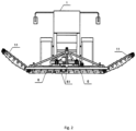
Fig. 2 front view of the motor vehicle with device as per the invention, -
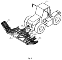
Fig. 3 spatial view of the motor vehicle with device as per the invention, -
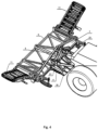
Fig. 4 sled run levelling device mounted on a motor vehicle, -
Fig. 5 front view of the sled run levelling device, -
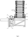
Fig. 6 bottom view of the sled run levelling device side snow scoop. -
Motor vehicle 1 comprising a device for levelling sled runs. The device comprises a truss attached tochassis 2 of the motor vehicle. To thatend chassis 2 hasbrackets 21 formain beam 3 of the truss. The truss performs a swinging motion relative tochassis 2 of the vehicle using actuator 4 connectingmain beam 3 of the truss with itsfunctional part 5. The truss features at least two symmetrically mountedscrew conveyors 6 shielded from the side of the motor vehicle byopen chute 7. The shaft of eachscrew conveyor 6 has two ends:internal end 61 andexternal end 62.Internal end 61 is connected to the drivetrain which comprisesgear system 81,bevel gear 82, telescopic universaljoint shaft 83 andvehicle drive shaft 84. Conveyor shaftinternal ends 61 are held directly ingear system 81 connected to other drivetrain elements.External ends 62 of each screw conveyor shaft are held inside bevel gear 9 powered byscrew conveyor 6 shaft.Screw conveyors 6 move accumulated snow towardsinternal ends 61 of their shafts, then the snow is compacted by compactingplate 10 mounted tochassis 2 of the vehicle behindopen chute 7. The device also featuressnow scoop 11. Aforementionedside bevel gear 9 transmits power toside shaft 12 ofside snow scoop 11.Side shaft 12 ofside snow scoop 11 is held inbearings 13 attached to the device truss.Side shaft 12 sets inmotion chain 14 of the snow scoop which hascombs 15 arranged along its length scooping and transporting snow from the bottom towards the top.
Claims (4)
- Motor vehicle (1) with a device levelling sled runs comprising a chassis (2) with a device attached to it constructed out of a truss, at least two screw conveyors (6) attached to the device truss, and shielded from the side of a motor vehicle by an open chute (7), wherein each screw conveyor (6) features a shaft with an internal end (61) connected to a drivetrain and external end (62) attached to the truss, characterized in that each screw conveyor (6)is arranged to perform a rotation around its axis of rotation so that the accumulated snow is moved towards internal end (61) of screw conveyors (6), and comprising an compacting plate (10), attached to the motor vehicle (1) chassis (2) behind open chute (7) of the screw conveyors (6).
- The motor vehicle according to claim 1 characterized in that it comprising at least one side snow scoop (11) in the form of a belt conveyor mounted on the device truss.
- The motor vehicle according to claim 1 or 2 characterized in that the side snow scoop (11) comprising a chain (14) with a combs (15), set in motion by side shaft (12) held in side bevel gear (9) powered by the screw conveyor (6) shaft.
- The motor vehicle according to claim 1 or 2 characterized in that it comprises at least one actuator (4) connecting a functional part (5) of the truss with its main beam (3) facilitating swinging motion of the functional part (5) of the truss relative to main beam (3) .
Applications Claiming Priority (1)
| Application Number | Priority Date | Filing Date | Title |
|---|---|---|---|
| PL439716A PL249083B1 (en) | 2021-11-30 | 2021-11-30 | Motor vehicle with a device for leveling a toboggan run |
Publications (3)
| Publication Number | Publication Date |
|---|---|
| EP4187016A1 true EP4187016A1 (en) | 2023-05-31 |
| EP4187016B1 EP4187016B1 (en) | 2025-05-07 |
| EP4187016C0 EP4187016C0 (en) | 2025-05-07 |
Family
ID=84361646
Family Applications (1)
| Application Number | Title | Priority Date | Filing Date |
|---|---|---|---|
| EP22000252.1A Active EP4187016B1 (en) | 2021-11-30 | 2022-11-22 | Motor vehicle with a device for levelling sled runs |
Country Status (2)
| Country | Link |
|---|---|
| EP (1) | EP4187016B1 (en) |
| PL (1) | PL249083B1 (en) |
Citations (6)
| Publication number | Priority date | Publication date | Assignee | Title |
|---|---|---|---|---|
| CA352708A (en) * | 1935-08-27 | Wandscheer Daniel | Snow plough | |
| CN2171633Y (en) * | 1993-08-14 | 1994-07-13 | 张继先 | Snow clearing and transporting vehicle |
| JP2007291842A (en) * | 2006-03-28 | 2007-11-08 | Nippo Corporation:Kk | Road surface forming device |
| WO2014122360A1 (en) * | 2013-02-11 | 2014-08-14 | Sother Oy | Snow loading machine |
| RU191994U1 (en) * | 2019-02-12 | 2019-08-29 | Общество с ограниченной ответственностью "БориноСервис" | ICE FILLING MACHINE AND ROLLER CARE |
| CN111472314A (en) | 2020-06-01 | 2020-07-31 | 门大智 | Multifunctional snow removing and loading machine |
-
2021
- 2021-11-30 PL PL439716A patent/PL249083B1/en unknown
-
2022
- 2022-11-22 EP EP22000252.1A patent/EP4187016B1/en active Active
Patent Citations (6)
| Publication number | Priority date | Publication date | Assignee | Title |
|---|---|---|---|---|
| CA352708A (en) * | 1935-08-27 | Wandscheer Daniel | Snow plough | |
| CN2171633Y (en) * | 1993-08-14 | 1994-07-13 | 张继先 | Snow clearing and transporting vehicle |
| JP2007291842A (en) * | 2006-03-28 | 2007-11-08 | Nippo Corporation:Kk | Road surface forming device |
| WO2014122360A1 (en) * | 2013-02-11 | 2014-08-14 | Sother Oy | Snow loading machine |
| RU191994U1 (en) * | 2019-02-12 | 2019-08-29 | Общество с ограниченной ответственностью "БориноСервис" | ICE FILLING MACHINE AND ROLLER CARE |
| CN111472314A (en) | 2020-06-01 | 2020-07-31 | 门大智 | Multifunctional snow removing and loading machine |
Also Published As
| Publication number | Publication date |
|---|---|
| PL439716A1 (en) | 2023-06-05 |
| EP4187016B1 (en) | 2025-05-07 |
| EP4187016C0 (en) | 2025-05-07 |
| PL249083B1 (en) | 2026-02-23 |
Similar Documents
| Publication | Publication Date | Title |
|---|---|---|
| US4280288A (en) | Modular draging unit for collecting solid bodies on an underwater bed | |
| US3213552A (en) | Snowplow | |
| EP4187016A1 (en) | Motor vehicle with a device for levelling sled runs | |
| EP1241298A2 (en) | Vehicle, especially for cleaning beaches | |
| US2171528A (en) | Apparatus for reclaiming ore and the like from storage piles | |
| US1844706A (en) | Snowplow | |
| EP3119667B1 (en) | Articulated vehicle | |
| US3966255A (en) | Bottom dump vehicle | |
| US1870591A (en) | Snowplow | |
| US1256642A (en) | Digging-disk feeder. | |
| CN108716207B (en) | Snow removing vehicle for clearing and transporting treasure | |
| US2709312A (en) | Side collector for mobile loader | |
| EP3552477A1 (en) | Hay windrower with oscillating baffle | |
| JPS6128079B2 (en) | ||
| US2569336A (en) | Coal mine haulage vehicle | |
| US1623910A (en) | Snow bemoveb | |
| US1214397A (en) | Snow shovel and loader. | |
| JP6869154B2 (en) | Walking blade work machine | |
| US3440739A (en) | Drive mechanism | |
| US947963A (en) | Sweeping-machine. | |
| CN103410114A (en) | Vibration type obstacle-crossing icebreaking shovel | |
| WO2016185453A1 (en) | An attachment for a prime mover | |
| US20100229518A1 (en) | Self propelled kit applicable to buckraking machines or silo-bag | |
| US1532723A (en) | Plow | |
| US3094794A (en) | Self-loading carry-all vehicle |
Legal Events
| Date | Code | Title | Description |
|---|---|---|---|
| PUAI | Public reference made under article 153(3) epc to a published international application that has entered the european phase |
Free format text: ORIGINAL CODE: 0009012 |
|
| STAA | Information on the status of an ep patent application or granted ep patent |
Free format text: STATUS: THE APPLICATION HAS BEEN PUBLISHED |
|
| AK | Designated contracting states |
Kind code of ref document: A1 Designated state(s): AL AT BE BG CH CY CZ DE DK EE ES FI FR GB GR HR HU IE IS IT LI LT LU LV MC ME MK MT NL NO PL PT RO RS SE SI SK SM TR |
|
| STAA | Information on the status of an ep patent application or granted ep patent |
Free format text: STATUS: REQUEST FOR EXAMINATION WAS MADE |
|
| 17P | Request for examination filed |
Effective date: 20230601 |
|
| RBV | Designated contracting states (corrected) |
Designated state(s): AL AT BE BG CH CY CZ DE DK EE ES FI FR GB GR HR HU IE IS IT LI LT LU LV MC ME MK MT NL NO PL PT RO RS SE SI SK SM TR |
|
| P01 | Opt-out of the competence of the unified patent court (upc) registered |
Effective date: 20230612 |
|
| GRAP | Despatch of communication of intention to grant a patent |
Free format text: ORIGINAL CODE: EPIDOSNIGR1 |
|
| STAA | Information on the status of an ep patent application or granted ep patent |
Free format text: STATUS: GRANT OF PATENT IS INTENDED |
|
| GRAS | Grant fee paid |
Free format text: ORIGINAL CODE: EPIDOSNIGR3 |
|
| INTG | Intention to grant announced |
Effective date: 20250303 |
|
| GRAA | (expected) grant |
Free format text: ORIGINAL CODE: 0009210 |
|
| STAA | Information on the status of an ep patent application or granted ep patent |
Free format text: STATUS: THE PATENT HAS BEEN GRANTED |
|
| AK | Designated contracting states |
Kind code of ref document: B1 Designated state(s): AL AT BE BG CH CY CZ DE DK EE ES FI FR GB GR HR HU IE IS IT LI LT LU LV MC ME MK MT NL NO PL PT RO RS SE SI SK SM TR |
|
| REG | Reference to a national code |
Ref country code: GB Ref legal event code: FG4D |
|
| REG | Reference to a national code |
Ref country code: CH Ref legal event code: EP |
|
| REG | Reference to a national code |
Ref country code: DE Ref legal event code: R096 Ref document number: 602022014057 Country of ref document: DE |
|
| REG | Reference to a national code |
Ref country code: IE Ref legal event code: FG4D |
|
| U01 | Request for unitary effect filed |
Effective date: 20250507 |
|
| P04 | Withdrawal of opt-out of the competence of the unified patent court (upc) registered |
Free format text: CASE NUMBER: APP_22422/2025 Effective date: 20250513 |
|
| U07 | Unitary effect registered |
Designated state(s): AT BE BG DE DK EE FI FR IT LT LU LV MT NL PT RO SE SI Effective date: 20250515 |
|
| PG25 | Lapsed in a contracting state [announced via postgrant information from national office to epo] |
Ref country code: ES Free format text: LAPSE BECAUSE OF FAILURE TO SUBMIT A TRANSLATION OF THE DESCRIPTION OR TO PAY THE FEE WITHIN THE PRESCRIBED TIME-LIMIT Effective date: 20250507 |
|
| PG25 | Lapsed in a contracting state [announced via postgrant information from national office to epo] |
Ref country code: GR Free format text: LAPSE BECAUSE OF FAILURE TO SUBMIT A TRANSLATION OF THE DESCRIPTION OR TO PAY THE FEE WITHIN THE PRESCRIBED TIME-LIMIT Effective date: 20250808 Ref country code: NO Free format text: LAPSE BECAUSE OF FAILURE TO SUBMIT A TRANSLATION OF THE DESCRIPTION OR TO PAY THE FEE WITHIN THE PRESCRIBED TIME-LIMIT Effective date: 20250807 |
|
| PG25 | Lapsed in a contracting state [announced via postgrant information from national office to epo] |
Ref country code: PL Free format text: LAPSE BECAUSE OF FAILURE TO SUBMIT A TRANSLATION OF THE DESCRIPTION OR TO PAY THE FEE WITHIN THE PRESCRIBED TIME-LIMIT Effective date: 20250507 |
|
| PG25 | Lapsed in a contracting state [announced via postgrant information from national office to epo] |
Ref country code: HR Free format text: LAPSE BECAUSE OF FAILURE TO SUBMIT A TRANSLATION OF THE DESCRIPTION OR TO PAY THE FEE WITHIN THE PRESCRIBED TIME-LIMIT Effective date: 20250507 |
|
| PG25 | Lapsed in a contracting state [announced via postgrant information from national office to epo] |
Ref country code: RS Free format text: LAPSE BECAUSE OF FAILURE TO SUBMIT A TRANSLATION OF THE DESCRIPTION OR TO PAY THE FEE WITHIN THE PRESCRIBED TIME-LIMIT Effective date: 20250807 |
|
| PG25 | Lapsed in a contracting state [announced via postgrant information from national office to epo] |
Ref country code: IS Free format text: LAPSE BECAUSE OF FAILURE TO SUBMIT A TRANSLATION OF THE DESCRIPTION OR TO PAY THE FEE WITHIN THE PRESCRIBED TIME-LIMIT Effective date: 20250907 |
|
| U20 | Renewal fee for the european patent with unitary effect paid |
Year of fee payment: 4 Effective date: 20251120 |
|
| PG25 | Lapsed in a contracting state [announced via postgrant information from national office to epo] |
Ref country code: SM Free format text: LAPSE BECAUSE OF FAILURE TO SUBMIT A TRANSLATION OF THE DESCRIPTION OR TO PAY THE FEE WITHIN THE PRESCRIBED TIME-LIMIT Effective date: 20250507 |
|
| PG25 | Lapsed in a contracting state [announced via postgrant information from national office to epo] |
Ref country code: CZ Free format text: LAPSE BECAUSE OF FAILURE TO SUBMIT A TRANSLATION OF THE DESCRIPTION OR TO PAY THE FEE WITHIN THE PRESCRIBED TIME-LIMIT Effective date: 20250507 |
|
| PG25 | Lapsed in a contracting state [announced via postgrant information from national office to epo] |
Ref country code: SK Free format text: LAPSE BECAUSE OF FAILURE TO SUBMIT A TRANSLATION OF THE DESCRIPTION OR TO PAY THE FEE WITHIN THE PRESCRIBED TIME-LIMIT Effective date: 20250507 |
|
| PLBE | No opposition filed within time limit |
Free format text: ORIGINAL CODE: 0009261 |
|
| STAA | Information on the status of an ep patent application or granted ep patent |
Free format text: STATUS: NO OPPOSITION FILED WITHIN TIME LIMIT |
|
| REG | Reference to a national code |
Ref country code: CH Ref legal event code: L10 Free format text: ST27 STATUS EVENT CODE: U-0-0-L10-L00 (AS PROVIDED BY THE NATIONAL OFFICE) Effective date: 20260318 |
|
| 26N | No opposition filed |
Effective date: 20260210 |