EP4187009A1 - A household appliance comprising a knob - Google Patents
A household appliance comprising a knob Download PDFInfo
- Publication number
- EP4187009A1 EP4187009A1 EP22199048.4A EP22199048A EP4187009A1 EP 4187009 A1 EP4187009 A1 EP 4187009A1 EP 22199048 A EP22199048 A EP 22199048A EP 4187009 A1 EP4187009 A1 EP 4187009A1
- Authority
- EP
- European Patent Office
- Prior art keywords
- household appliance
- fixing
- fixing member
- claw
- housing
- Prior art date
- Legal status (The legal status is an assumption and is not a legal conclusion. Google has not performed a legal analysis and makes no representation as to the accuracy of the status listed.)
- Granted
Links
Images


Classifications
-
- D—TEXTILES; PAPER
- D06—TREATMENT OF TEXTILES OR THE LIKE; LAUNDERING; FLEXIBLE MATERIALS NOT OTHERWISE PROVIDED FOR
- D06F—LAUNDERING, DRYING, IRONING, PRESSING OR FOLDING TEXTILE ARTICLES
- D06F34/00—Details of control systems for washing machines, washer-dryers or laundry dryers
- D06F34/28—Arrangements for programme selection, e.g. control panels therefor; Arrangements for indicating programme parameters, e.g. the selected programme or its progress
- D06F34/30—Arrangements for programme selection, e.g. control panels therefor; Arrangements for indicating programme parameters, e.g. the selected programme or its progress characterised by mechanical features, e.g. buttons or rotary dials
-
- A—HUMAN NECESSITIES
- A47—FURNITURE; DOMESTIC ARTICLES OR APPLIANCES; COFFEE MILLS; SPICE MILLS; SUCTION CLEANERS IN GENERAL
- A47L—DOMESTIC WASHING OR CLEANING; SUCTION CLEANERS IN GENERAL
- A47L15/00—Washing or rinsing machines for crockery or tableware
- A47L15/42—Details
- A47L15/4293—Arrangements for programme selection, e.g. control panels; Indication of the selected programme, programme progress or other parameters of the programme, e.g. by using display panels
-
- G—PHYSICS
- G05—CONTROLLING; REGULATING
- G05G—CONTROL DEVICES OR SYSTEMS INSOFAR AS CHARACTERISED BY MECHANICAL FEATURES ONLY
- G05G1/00—Controlling members, e.g. knobs or handles; Assemblies or arrangements thereof; Indicating position of controlling members
- G05G1/08—Controlling members for hand actuation by rotary movement, e.g. hand wheels
Definitions
- the present invention relates to a household appliance comprising a rotary knob which is mounted to the control panel.
- Household appliances such as laundry washing/drying machines, cooking appliances, dishwashers, etc. usually comprise a control panel whereon rotary knobs which enable the operational status to be determined as per the preference of the users are disposed.
- the knobs are attached to a shaft connected to the control card disposed behind the control panel by means of the housings on the control panel. When the user rotates the knob, the movement is transferred to the shaft such that the user preference is transmitted to the control card.
- the knobs which are directly related to the use of the household appliance, are one of the most used components on the household appliance by the user, and are generally configured as multi-part components in line with various cosmetic needs and structural designs to increase the quality perception of the users.
- One embodiment preferred by the manufacturers to increase the quality perception of the knobs is to increase the weight of the knob by placing various weight pieces inside the knob to provide a strong feel.
- the aim of the present invention is the realization of a household appliance comprising a knob with decreased operating defects and improved quality perception.
- the household appliance realized in order to attain the aim of the present invention, explicated in the first claim and the respective claims thereof, comprises a panel; a gap-shaped housing which is arranged on the panel; a control card which controls the household appliance, which receives the preferences of the user and which is connected to a shaft extending outwards from the housing; and a knob having a bearing wherein the shaft is seated, an intermediate member which is fitted into the housing from behind the panel, a handle which is provided in front of the panel and which is suitable to be moved by the user and a fixing member whereon the intermediate member and the handle are fixed, which provides the connection between the intermediate member and the handle and which is manufactured from metal.
- the intermediate member and the handle are directly fixed onto the metal fixing member.
- the fixing member While centering the intermediate member and the handle relative to each other, the fixing member also provides the elimination of stretching and increases the weight of the knob by acting as a weight.
- the metal fixing member which supports and centers the handle and the intermediate member, production and assembly tolerances are decreased and the weight of the knob is increased without the need for a separate weight piece mounting.
- the handle is composed of a plurality of components and each component is fixed to the fixing member.
- the handle is configured in at least two components, a circumferential wall defining the lateral circumferential surface thereof and a cover defining the front face thereof, and the circumferential wall and the cover are fixed onto the intermediate member without being directly fixed to each other so as to be seated on top of each other.
- the cover is configured as a multi-part component so as to have a frame and a plate, and the frame and the plate are fixed to the fixing member.
- the household appliance comprises the intermediate member having a support portion extending out of the housing, and the fixing member having a body which is fitted over the support portion and remains between the support portion and the circumferential wall so as to be fixed on the support portion and the circumferential wall.
- the body is a hollow cylinder and is fitted over the support portion while the circumferential wall is fixed to the body.
- first claw on the outside of the support facing the circumferential wall and at least one second claw on the inside of the body facing the circumferential wall while the circumferential wall has at least one first claw housing wherein the first claw is fitted, and at least one second claw housing wherein the second claw is fitted.
- the first claw and the second claw which are provided on the handle and the intermediate member and which are manufactured from a more flexible material relative to the fixing member, for example plastic material, stretch during the assembly so as to be fitted into the housings on the circumferential wall.
- a skirt extending almost perpendicular to the body is provided on the fixing member and the cover is fixed onto the skirt.
- the frame and the plate are fixed on the fixing member without being fixed to each other.
- the skirt provides support to the cover, which is manufactured from a material with less resistance.
- the fixing member is manufactured from zamak.
- the fixing member is enabled to be low cost and have high strength, and in case the household appliance is placed in a high humidity environment such as a bathroom or used with wet hands, the liquid reaching the fixing member through the mounting gaps is prevented from causing wear and corrosion over time.
- the household appliance (1) comprises a panel (2) which enables the user to control the functions of the household appliance (1); a control unit (3) which is disposed behind the panel (2); a shaft (4) which transmits the preferences of the user to the control unit (3) and which is connected to the control unit (3); a housing (5) which is arranged on the panel (2); and a knob (9) having a bearing 6) which bears the shaft (4), an intermediate member (7) which is fitted into the housing (5) so as to bear against the panel (2) from behind, and a handle (8) which enables the user to move the shaft (4).
- the household appliance (1) of the present invention comprises the knob (9) having a metal fixing member (10) whereon the intermediate member (7) and the handle (8) are fixed.
- the fixing member (10) is manufactured from metal while the intermediate member (7) and the handle (8) can be manufactured from various materials, such as plastic, which are low cost or which are preferred due to the outer appearance.
- the fixing member (10) provides high rigidity and significantly increases the weight of the knob (9).
- the household appliance (1) comprises the handle (8) composed of at least two components, each fixed onto the fixing member (10), one being a circumferential wall (12) and the other being a cover (20) positioned in front of the circumferential wall (12).
- the household appliance (1) comprises a support portion (11) which is arranged on the intermediate member (7) and which extends outwards from the housing (5), and the fixing member (10) having a body (13) which at least partially remains between the support portion (11) and the circumferential wall (12) and whereon the support portion (11) and the circumferential wall (12) are fixed.
- the household appliance (1) comprises at least one first fixing claw (14) which is provided on the support portion (11), at least one second fixing claw (15) which is provided on the circumferential wall (12), and the body (13) having at least one first fixing housing (16) wherein the first fixing claw (14) is fitted and at least one second fixing housing (17) wherein the second fixing claw (15) is fitted.
- the household appliance (1) comprises at least one skirt (21) which is provided on the fixing member (10), which extends almost perpendicular to the body (13) and whereon the cover (20) is fixed.
- the household appliance (1) comprises the cover (20) having a frame (18) which is fixed onto the fixing member (10) and which surrounds the side of the circumferential wall (12) and a plate (19) which is fitted into the frame (18) fixed onto the fixing member (10).
- the household appliance (1) comprises at least one third claw (22) which is provided on the plate (19), at least one fourth claw (23) which is provided on the frame (18), and at least one third fixing housing (24) and at least one fourth fixing member (25) which are provided on the skirt (21) and which receives the third fixing claw (22) and the fourth fixing claw (23), respectively.
- the household appliance (1) comprises the fixing member (10) manufactured from zamak.
- the handle (8) has a cover (20) which is disposed on the front surface of the body (13) and the cover (20) is fixed to the fixing member (10).
- the cover (20) is only seated onto the body (13) and fixed onto the fixing member (10) without being directly fixed onto the body (13).
- the body (13) and the cover (20) are centered by means of the fixing member (10), and the gaps and eccentricities between the cover (20) and the body (13) caused by the assembly and production tolerances are prevented from causing the knob (9) to malfunction.
- a household appliance (1) comprising a multi-part knob (9) with increased quality perception and improved ease of assembly.
Landscapes
- Engineering & Computer Science (AREA)
- Textile Engineering (AREA)
- Mechanical Control Devices (AREA)
Abstract
Description
- The present invention relates to a household appliance comprising a rotary knob which is mounted to the control panel.
- Household appliances such as laundry washing/drying machines, cooking appliances, dishwashers, etc. usually comprise a control panel whereon rotary knobs which enable the operational status to be determined as per the preference of the users are disposed. The knobs are attached to a shaft connected to the control card disposed behind the control panel by means of the housings on the control panel. When the user rotates the knob, the movement is transferred to the shaft such that the user preference is transmitted to the control card. The knobs, which are directly related to the use of the household appliance, are one of the most used components on the household appliance by the user, and are generally configured as multi-part components in line with various cosmetic needs and structural designs to increase the quality perception of the users. One embodiment preferred by the manufacturers to increase the quality perception of the knobs is to increase the weight of the knob by placing various weight pieces inside the knob to provide a strong feel. However, there may be deviations in the components which are fixed to each other and in the position of the shaft due to production tolerances and shifts which may occur during assembly, and moreover, as the number of components increases, operating defects such as wobbly and free rotation caused by production and assembly, which cause a decrease in the quality perception of the users, increase.
- In the state of the art International Patent Application No.
WO2018054801 , a household appliance comprising a knob having weight pieces is disclosed. - The aim of the present invention is the realization of a household appliance comprising a knob with decreased operating defects and improved quality perception.
- The household appliance realized in order to attain the aim of the present invention, explicated in the first claim and the respective claims thereof, comprises a panel; a gap-shaped housing which is arranged on the panel; a control card which controls the household appliance, which receives the preferences of the user and which is connected to a shaft extending outwards from the housing; and a knob having a bearing wherein the shaft is seated, an intermediate member which is fitted into the housing from behind the panel, a handle which is provided in front of the panel and which is suitable to be moved by the user and a fixing member whereon the intermediate member and the handle are fixed, which provides the connection between the intermediate member and the handle and which is manufactured from metal. The intermediate member and the handle are directly fixed onto the metal fixing member. While centering the intermediate member and the handle relative to each other, the fixing member also provides the elimination of stretching and increases the weight of the knob by acting as a weight. By means of the metal fixing member which supports and centers the handle and the intermediate member, production and assembly tolerances are decreased and the weight of the knob is increased without the need for a separate weight piece mounting.
- In another embodiment of the present invention, the handle is composed of a plurality of components and each component is fixed to the fixing member. The handle is configured in at least two components, a circumferential wall defining the lateral circumferential surface thereof and a cover defining the front face thereof, and the circumferential wall and the cover are fixed onto the intermediate member without being directly fixed to each other so as to be seated on top of each other. In a version of this embodiment, the cover is configured as a multi-part component so as to have a frame and a plate, and the frame and the plate are fixed to the fixing member. Thus, each component of the handle as well as the intermediate member are fixed to the fixing member and centered by means of the fixing member. Consequently, due to the individual fixing of the components of the handle, possible misalignments and eccentricities between the components are eliminated and concentric fixation is provided.
- In another embodiment of the present invention, the household appliance comprises the intermediate member having a support portion extending out of the housing, and the fixing member having a body which is fitted over the support portion and remains between the support portion and the circumferential wall so as to be fixed on the support portion and the circumferential wall. The body is a hollow cylinder and is fitted over the support portion while the circumferential wall is fixed to the body. Thus, in this way, the eccentricities between the circumferential wall and the intermediate member are prevented such that the body movement is transmitted to the intermediate member without any gap and the fixing member advantageously creates a weight inside the body.
- In another embodiment of the present invention, there is at least one first claw on the outside of the support facing the circumferential wall and at least one second claw on the inside of the body facing the circumferential wall while the circumferential wall has at least one first claw housing wherein the first claw is fitted, and at least one second claw housing wherein the second claw is fitted. The first claw and the second claw which are provided on the handle and the intermediate member and which are manufactured from a more flexible material relative to the fixing member, for example plastic material, stretch during the assembly so as to be fitted into the housings on the circumferential wall. Thus, it is ensured that the body and the intermediate member are fixed to the fixing member quickly and securely without being screwed.
- In another embodiment of the present invention, a skirt extending almost perpendicular to the body is provided on the fixing member and the cover is fixed onto the skirt. In a preferred version of this embodiment, the frame and the plate are fixed on the fixing member without being fixed to each other. Thus, the skirt provides support to the cover, which is manufactured from a material with less resistance. By means of the skirt, weight is provided also on the front of the handle and the weight of the knob is advantageously transferred to the front of the handle.
- In another embodiment of the present invention, there is at least one third claw on the frame and at least one fourth claw on the front plate while at least one third housing wherein the third claw is fitted and at least one fourth housing wherein the fourth claw is fitted are arranged on the skirt. Thus, each of the intermediate member, body, frame and front plate is fixed on and supported by the fixing member. Consequently, possible misalignments and eccentricities of each component relative to each other are tolerated. In an embodiment of the present invention, the fixing member is manufactured from zamak. Thus, the fixing member is enabled to be low cost and have high strength, and in case the household appliance is placed in a high humidity environment such as a bathroom or used with wet hands, the liquid reaching the fixing member through the mounting gaps is prevented from causing wear and corrosion over time.
- By means of the present invention, it is ensured that the handle and the intermediate member manufactured from flexible material suitable for decorative shaping are carried and supported by the metal fixing member and operation faults caused by production and assembly errors are eliminated while the weight of the knob is increased.
- The household appliance realized in order to attain the aim of the present invention is illustrated in the attached figures, where:
-
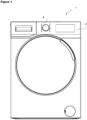
Figure 1 - is the perspective view of the washing machine related to an embodiment wherein the household appliance of the present invention is a washing machine. -
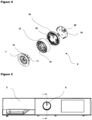
Figure 2 - is the exploded view of the panel, the knob and the control unit in an embodiment of the present invention. -
Figure 3 - is the exploded view of the knob group in an embodiment of the present invention. -
Figure 4 - is the view showing the knob components to which the fixing member and the circumferential wall are connected. -
Figure 5 - is the view showing the mounting of the knob to the panel in an embodiment of the present invention. -
Figure 6 - is the view of the cross-section B-B inFigure 5 . - The elements illustrated in the figures are numbered as follows:
- 1. Household appliance
- 2. Panel
- 3. Control unit
- 4. Shaft
- 5. Housing
- 6. Bearing
- 7. Intermediate member
- 8. Handle
- 9. Knob
- 10. Fixing member
- 11. Support portion
- 12. Circumferential wall
- 13. Body
- 14. First fixing claw
- 15. Second fixing claw
- 16. First fixing housing
- 17. Second fixing housing
- 18. Frame
- 19. Plate
- 20. Cover
- 21. Skirt
- 22. Third fixing claw
- 23. Fourth fixing claw
- 24. Third fixing housing
- 25. Fourth fixing housing
- The household appliance (1) comprises a panel (2) which enables the user to control the functions of the household appliance (1); a control unit (3) which is disposed behind the panel (2); a shaft (4) which transmits the preferences of the user to the control unit (3) and which is connected to the control unit (3); a housing (5) which is arranged on the panel (2); and a knob (9) having a bearing 6) which bears the shaft (4), an intermediate member (7) which is fitted into the housing (5) so as to bear against the panel (2) from behind, and a handle (8) which enables the user to move the shaft (4).
- The household appliance (1) of the present invention comprises the knob (9) having a metal fixing member (10) whereon the intermediate member (7) and the handle (8) are fixed.
- In the household appliance (1) of the present invention, the fixing member (10) is manufactured from metal while the intermediate member (7) and the handle (8) can be manufactured from various materials, such as plastic, which are low cost or which are preferred due to the outer appearance. Thus, the fixing member (10) provides high rigidity and significantly increases the weight of the knob (9).
- In an embodiment of the present invention, the household appliance (1) comprises the handle (8) composed of at least two components, each fixed onto the fixing member (10), one being a circumferential wall (12) and the other being a cover (20) positioned in front of the circumferential wall (12).
- In an embodiment of the present invention, the household appliance (1) comprises a support portion (11) which is arranged on the intermediate member (7) and which extends outwards from the housing (5), and the fixing member (10) having a body (13) which at least partially remains between the support portion (11) and the circumferential wall (12) and whereon the support portion (11) and the circumferential wall (12) are fixed.
- In an embodiment of the present invention, the household appliance (1) comprises at least one first fixing claw (14) which is provided on the support portion (11), at least one second fixing claw (15) which is provided on the circumferential wall (12), and the body (13) having at least one first fixing housing (16) wherein the first fixing claw (14) is fitted and at least one second fixing housing (17) wherein the second fixing claw (15) is fitted.
- In an embodiment of the present invention, the household appliance (1) comprises at least one skirt (21) which is provided on the fixing member (10), which extends almost perpendicular to the body (13) and whereon the cover (20) is fixed.
- In an embodiment of the present invention, the household appliance (1) comprises the cover (20) having a frame (18) which is fixed onto the fixing member (10) and which surrounds the side of the circumferential wall (12) and a plate (19) which is fitted into the frame (18) fixed onto the fixing member (10).
- In an embodiment of the present invention, the household appliance (1) comprises at least one third claw (22) which is provided on the plate (19), at least one fourth claw (23) which is provided on the frame (18), and at least one third fixing housing (24) and at least one fourth fixing member (25) which are provided on the skirt (21) and which receives the third fixing claw (22) and the fourth fixing claw (23), respectively.
- In an embodiment of the present invention, the household appliance (1) comprises the fixing member (10) manufactured from zamak.
- In another embodiment of the present invention, the handle (8) has a cover (20) which is disposed on the front surface of the body (13) and the cover (20) is fixed to the fixing member (10). The cover (20) is only seated onto the body (13) and fixed onto the fixing member (10) without being directly fixed onto the body (13). Thus, the body (13) and the cover (20) are centered by means of the fixing member (10), and the gaps and eccentricities between the cover (20) and the body (13) caused by the assembly and production tolerances are prevented from causing the knob (9) to malfunction.
- By means of the present invention, a household appliance (1) is realized, comprising a multi-part knob (9) with increased quality perception and improved ease of assembly.
Claims (8)
- A household appliance (1) comprising a panel (2) which enables the user to control the functions of the household appliance (1); a control unit (3) which is disposed behind the panel (2); a shaft (4) which transmits the preferences of the user to the control unit (3) and which is connected to the control unit (3); a housing (5) which is arranged on the panel (2); and a knob (9) having a bearing 6) which bears the shaft (4), an intermediate member (7) which is fitted into the housing (5) so as to bear against the panel (2) from behind, and a handle (8) which enables the user to move the shaft (4), characterized by the knob (9) having a metal fixing member (10) whereon the intermediate member (7) and the handle (8) are fixed.
- A household appliance (1) as in Claim 1, characterized by the handle (8) composed of at least two components, each fixed onto the fixing member (10), one being a circumferential wall (12) and the other being a cover (20) positioned in front of the circumferential wall (12).
- A household appliance (1) as in Claim 1, characterized by a support portion (11) which is arranged on the intermediate member (7) and which extends outwards from the housing (5), and the fixing member (10) having a body (13) which at least partially remains between the support portion (11) and the circumferential wall (12) and whereon the support portion (11) and the circumferential wall (12) are fixed.
- A household appliance (1) as in Claim 3, characterized by at least one first fixing claw (14) which is provided on the support portion (11), at least one second fixing claw (15) which is provided on the circumferential wall (12), and the body (13) having at least one first fixing housing (16) wherein the first fixing claw (14) is fitted and at least one second fixing housing (17) wherein the second fixing claw (15) is fitted.
- A household appliance (1) as in any one of the Claims 2 to 4, characterized by at least one skirt (21) which is provided on the fixing member (10), which extends almost perpendicular to the body (13) and whereon the cover (20) is fixed.
- A household appliance (1) as in Claim 5, characterized by the cover (20) having a frame (18) which is fixed onto the fixing member (10) and which surrounds the side of the circumferential wall (12) and a plate (19) which is fitted into the frame (18) fixed onto the fixing member (10).
- A household appliance (1) as in Claim 6, characterized by at least one third claw (22) which is provided on the plate (19), at least one fourth claw (23) which is provided on the frame (18), and at least one third fixing housing (24) and at least one fourth fixing member (25) which are provided on the skirt (21) and which receives the third fixing claw (22) and the fourth fixing claw (23), respectively.
- A household appliance (1) as in any one of the above claims, characterized by the fixing member (10) which is manufactured from zamak.
Applications Claiming Priority (1)
| Application Number | Priority Date | Filing Date | Title |
|---|---|---|---|
| TR202118854 | 2021-11-30 |
Publications (2)
| Publication Number | Publication Date |
|---|---|
| EP4187009A1 true EP4187009A1 (en) | 2023-05-31 |
| EP4187009B1 EP4187009B1 (en) | 2025-01-01 |
Family
ID=83546744
Family Applications (1)
| Application Number | Title | Priority Date | Filing Date |
|---|---|---|---|
| EP22199048.4A Active EP4187009B1 (en) | 2021-11-30 | 2022-09-30 | A household appliance comprising a knob |
Country Status (2)
| Country | Link |
|---|---|
| EP (1) | EP4187009B1 (en) |
| PL (1) | PL4187009T3 (en) |
Cited By (1)
| Publication number | Priority date | Publication date | Assignee | Title |
|---|---|---|---|---|
| US12554344B1 (en) | 2024-09-30 | 2026-02-17 | Whirlpool Corporation | Snap-in knob for an appliance console |
Citations (3)
| Publication number | Priority date | Publication date | Assignee | Title |
|---|---|---|---|---|
| WO2007043819A1 (en) * | 2005-10-12 | 2007-04-19 | Lg Electronics Inc. | Control unit of laundry processing apparatus |
| KR20100052211A (en) * | 2008-11-10 | 2010-05-19 | 엘지전자 주식회사 | Washing machine |
| WO2018054801A1 (en) | 2016-09-20 | 2018-03-29 | Arcelik Anonim Sirketi | A household appliance comprising a knob |
-
2022
- 2022-09-30 PL PL22199048.4T patent/PL4187009T3/en unknown
- 2022-09-30 EP EP22199048.4A patent/EP4187009B1/en active Active
Patent Citations (3)
| Publication number | Priority date | Publication date | Assignee | Title |
|---|---|---|---|---|
| WO2007043819A1 (en) * | 2005-10-12 | 2007-04-19 | Lg Electronics Inc. | Control unit of laundry processing apparatus |
| KR20100052211A (en) * | 2008-11-10 | 2010-05-19 | 엘지전자 주식회사 | Washing machine |
| WO2018054801A1 (en) | 2016-09-20 | 2018-03-29 | Arcelik Anonim Sirketi | A household appliance comprising a knob |
Cited By (1)
| Publication number | Priority date | Publication date | Assignee | Title |
|---|---|---|---|---|
| US12554344B1 (en) | 2024-09-30 | 2026-02-17 | Whirlpool Corporation | Snap-in knob for an appliance console |
Also Published As
| Publication number | Publication date |
|---|---|
| EP4187009B1 (en) | 2025-01-01 |
| PL4187009T3 (en) | 2025-04-28 |
Similar Documents
| Publication | Publication Date | Title |
|---|---|---|
| EP2602377B1 (en) | Washing machine having a knob assembly | |
| CN209215975U (en) | Electrical equipment including knob device | |
| EP2140058B1 (en) | Laundry treating apparatus | |
| US8151603B2 (en) | Door for washing machine | |
| US9297109B2 (en) | Laundry dryer | |
| EP3516103B1 (en) | A household appliance comprising a knob | |
| EP4187009B1 (en) | A household appliance comprising a knob | |
| KR20160084073A (en) | Laundry treating apparatus and door assembly thereof | |
| EP2039821B1 (en) | Knob assembly for laundry machine and manufacturing method thereof | |
| US20100043499A1 (en) | Control unit of laundry processing apparatus | |
| GB2130438A (en) | Rotary knob | |
| WO2017020959A1 (en) | Laundry treatment machine with a front door handle mounting mechanism | |
| EP2436828B1 (en) | A control panel assembly for a domestic appliance | |
| EP3351858B1 (en) | Household appliance having a control panel | |
| PL1696070T3 (en) | Washing machine or similar household appliance activated by a synchronous electric motor with a detecting device of unbalance conditions | |
| KR20180101824A (en) | Washing machine | |
| WO2013098243A2 (en) | A household appliance | |
| EP2764524B1 (en) | Household appliance with turn knob | |
| EP3447182B1 (en) | Household appliance and method for operating a household appliance | |
| CN113611559B (en) | Knob operation components and home appliances | |
| TR2021018854A2 (en) | A HOME DEVICE WITH ONE BUTTON | |
| KR101706969B1 (en) | Laundry treating apparatus and door assembly thereof | |
| WO2016193369A1 (en) | Household appliance with adjustable height controlled from the front | |
| EP4202104B1 (en) | A washing machine | |
| WO2020126468A1 (en) | A household appliance comprising a decorative element which can be attached to/detached from the knob |
Legal Events
| Date | Code | Title | Description |
|---|---|---|---|
| PUAI | Public reference made under article 153(3) epc to a published international application that has entered the european phase |
Free format text: ORIGINAL CODE: 0009012 |
|
| STAA | Information on the status of an ep patent application or granted ep patent |
Free format text: STATUS: REQUEST FOR EXAMINATION WAS MADE |
|
| 17P | Request for examination filed |
Effective date: 20220930 |
|
| AK | Designated contracting states |
Kind code of ref document: A1 Designated state(s): AL AT BE BG CH CY CZ DE DK EE ES FI FR GB GR HR HU IE IS IT LI LT LU LV MC MK MT NL NO PL PT RO RS SE SI SK SM TR |
|
| GRAP | Despatch of communication of intention to grant a patent |
Free format text: ORIGINAL CODE: EPIDOSNIGR1 |
|
| STAA | Information on the status of an ep patent application or granted ep patent |
Free format text: STATUS: GRANT OF PATENT IS INTENDED |
|
| RIC1 | Information provided on ipc code assigned before grant |
Ipc: G05G 1/08 20060101ALN20240802BHEP Ipc: A47L 15/42 20060101ALN20240802BHEP Ipc: D06F 34/30 20200101AFI20240802BHEP |
|
| INTG | Intention to grant announced |
Effective date: 20240826 |
|
| GRAS | Grant fee paid |
Free format text: ORIGINAL CODE: EPIDOSNIGR3 |
|
| GRAA | (expected) grant |
Free format text: ORIGINAL CODE: 0009210 |
|
| STAA | Information on the status of an ep patent application or granted ep patent |
Free format text: STATUS: THE PATENT HAS BEEN GRANTED |
|
| AK | Designated contracting states |
Kind code of ref document: B1 Designated state(s): AL AT BE BG CH CY CZ DE DK EE ES FI FR GB GR HR HU IE IS IT LI LT LU LV MC MK MT NL NO PL PT RO RS SE SI SK SM TR |
|
| REG | Reference to a national code |
Ref country code: GB Ref legal event code: FG4D |
|
| REG | Reference to a national code |
Ref country code: DE Ref legal event code: R096 Ref document number: 602022009286 Country of ref document: DE |
|
| REG | Reference to a national code |
Ref country code: CH Ref legal event code: EP |
|
| REG | Reference to a national code |
Ref country code: IE Ref legal event code: FG4D |
|
| REG | Reference to a national code |
Ref country code: LT Ref legal event code: MG9D |
|
| REG | Reference to a national code |
Ref country code: NL Ref legal event code: MP Effective date: 20250101 |
|
| REG | Reference to a national code |
Ref country code: AT Ref legal event code: MK05 Ref document number: 1756334 Country of ref document: AT Kind code of ref document: T Effective date: 20250101 |
|
| PG25 | Lapsed in a contracting state [announced via postgrant information from national office to epo] |
Ref country code: NL Free format text: LAPSE BECAUSE OF FAILURE TO SUBMIT A TRANSLATION OF THE DESCRIPTION OR TO PAY THE FEE WITHIN THE PRESCRIBED TIME-LIMIT Effective date: 20250101 |
|
| PG25 | Lapsed in a contracting state [announced via postgrant information from national office to epo] |
Ref country code: FI Free format text: LAPSE BECAUSE OF FAILURE TO SUBMIT A TRANSLATION OF THE DESCRIPTION OR TO PAY THE FEE WITHIN THE PRESCRIBED TIME-LIMIT Effective date: 20250101 |
|
| PG25 | Lapsed in a contracting state [announced via postgrant information from national office to epo] |
Ref country code: ES Free format text: LAPSE BECAUSE OF FAILURE TO SUBMIT A TRANSLATION OF THE DESCRIPTION OR TO PAY THE FEE WITHIN THE PRESCRIBED TIME-LIMIT Effective date: 20250101 |
|
| PG25 | Lapsed in a contracting state [announced via postgrant information from national office to epo] |
Ref country code: IS Free format text: LAPSE BECAUSE OF FAILURE TO SUBMIT A TRANSLATION OF THE DESCRIPTION OR TO PAY THE FEE WITHIN THE PRESCRIBED TIME-LIMIT Effective date: 20250501 Ref country code: NO Free format text: LAPSE BECAUSE OF FAILURE TO SUBMIT A TRANSLATION OF THE DESCRIPTION OR TO PAY THE FEE WITHIN THE PRESCRIBED TIME-LIMIT Effective date: 20250401 |
|
| PG25 | Lapsed in a contracting state [announced via postgrant information from national office to epo] |
Ref country code: HR Free format text: LAPSE BECAUSE OF FAILURE TO SUBMIT A TRANSLATION OF THE DESCRIPTION OR TO PAY THE FEE WITHIN THE PRESCRIBED TIME-LIMIT Effective date: 20250101 |
|
| PG25 | Lapsed in a contracting state [announced via postgrant information from national office to epo] |
Ref country code: LV Free format text: LAPSE BECAUSE OF FAILURE TO SUBMIT A TRANSLATION OF THE DESCRIPTION OR TO PAY THE FEE WITHIN THE PRESCRIBED TIME-LIMIT Effective date: 20250101 Ref country code: PT Free format text: LAPSE BECAUSE OF FAILURE TO SUBMIT A TRANSLATION OF THE DESCRIPTION OR TO PAY THE FEE WITHIN THE PRESCRIBED TIME-LIMIT Effective date: 20250502 |
|
| PG25 | Lapsed in a contracting state [announced via postgrant information from national office to epo] |
Ref country code: BG Free format text: LAPSE BECAUSE OF FAILURE TO SUBMIT A TRANSLATION OF THE DESCRIPTION OR TO PAY THE FEE WITHIN THE PRESCRIBED TIME-LIMIT Effective date: 20250101 Ref country code: GR Free format text: LAPSE BECAUSE OF FAILURE TO SUBMIT A TRANSLATION OF THE DESCRIPTION OR TO PAY THE FEE WITHIN THE PRESCRIBED TIME-LIMIT Effective date: 20250402 |
|
| PG25 | Lapsed in a contracting state [announced via postgrant information from national office to epo] |
Ref country code: AT Free format text: LAPSE BECAUSE OF FAILURE TO SUBMIT A TRANSLATION OF THE DESCRIPTION OR TO PAY THE FEE WITHIN THE PRESCRIBED TIME-LIMIT Effective date: 20250101 |
|
| PG25 | Lapsed in a contracting state [announced via postgrant information from national office to epo] |
Ref country code: CZ Free format text: LAPSE BECAUSE OF FAILURE TO SUBMIT A TRANSLATION OF THE DESCRIPTION OR TO PAY THE FEE WITHIN THE PRESCRIBED TIME-LIMIT Effective date: 20250101 |
|
| PG25 | Lapsed in a contracting state [announced via postgrant information from national office to epo] |
Ref country code: SE Free format text: LAPSE BECAUSE OF FAILURE TO SUBMIT A TRANSLATION OF THE DESCRIPTION OR TO PAY THE FEE WITHIN THE PRESCRIBED TIME-LIMIT Effective date: 20250101 |
|
| REG | Reference to a national code |
Ref country code: DE Ref legal event code: R097 Ref document number: 602022009286 Country of ref document: DE |
|
| PG25 | Lapsed in a contracting state [announced via postgrant information from national office to epo] |
Ref country code: SM Free format text: LAPSE BECAUSE OF FAILURE TO SUBMIT A TRANSLATION OF THE DESCRIPTION OR TO PAY THE FEE WITHIN THE PRESCRIBED TIME-LIMIT Effective date: 20250101 |
|
| PG25 | Lapsed in a contracting state [announced via postgrant information from national office to epo] |
Ref country code: DK Free format text: LAPSE BECAUSE OF FAILURE TO SUBMIT A TRANSLATION OF THE DESCRIPTION OR TO PAY THE FEE WITHIN THE PRESCRIBED TIME-LIMIT Effective date: 20250101 |
|
| PGFP | Annual fee paid to national office [announced via postgrant information from national office to epo] |
Ref country code: DE Payment date: 20250919 Year of fee payment: 4 |
|
| PGFP | Annual fee paid to national office [announced via postgrant information from national office to epo] |
Ref country code: TR Payment date: 20250919 Year of fee payment: 4 Ref country code: PL Payment date: 20250923 Year of fee payment: 4 |
|
| PGFP | Annual fee paid to national office [announced via postgrant information from national office to epo] |
Ref country code: FR Payment date: 20250922 Year of fee payment: 4 |
|
| PG25 | Lapsed in a contracting state [announced via postgrant information from national office to epo] |
Ref country code: EE Free format text: LAPSE BECAUSE OF FAILURE TO SUBMIT A TRANSLATION OF THE DESCRIPTION OR TO PAY THE FEE WITHIN THE PRESCRIBED TIME-LIMIT Effective date: 20250101 |
|
| PG25 | Lapsed in a contracting state [announced via postgrant information from national office to epo] |
Ref country code: RO Free format text: LAPSE BECAUSE OF FAILURE TO SUBMIT A TRANSLATION OF THE DESCRIPTION OR TO PAY THE FEE WITHIN THE PRESCRIBED TIME-LIMIT Effective date: 20250101 |
|
| PG25 | Lapsed in a contracting state [announced via postgrant information from national office to epo] |
Ref country code: SK Free format text: LAPSE BECAUSE OF FAILURE TO SUBMIT A TRANSLATION OF THE DESCRIPTION OR TO PAY THE FEE WITHIN THE PRESCRIBED TIME-LIMIT Effective date: 20250101 |
|
| PLBE | No opposition filed within time limit |
Free format text: ORIGINAL CODE: 0009261 |
|
| STAA | Information on the status of an ep patent application or granted ep patent |
Free format text: STATUS: NO OPPOSITION FILED WITHIN TIME LIMIT |
|
| REG | Reference to a national code |
Ref country code: CH Ref legal event code: L10 Free format text: ST27 STATUS EVENT CODE: U-0-0-L10-L00 (AS PROVIDED BY THE NATIONAL OFFICE) Effective date: 20251112 |
|
| 26N | No opposition filed |
Effective date: 20251002 |
|
| PGFP | Annual fee paid to national office [announced via postgrant information from national office to epo] |
Ref country code: IT Payment date: 20250930 Year of fee payment: 4 |
|
| REG | Reference to a national code |
Ref country code: CH Ref legal event code: H13 Free format text: ST27 STATUS EVENT CODE: U-0-0-H10-H13 (AS PROVIDED BY THE NATIONAL OFFICE) Effective date: 20260504 |
|
| PG25 | Lapsed in a contracting state [announced via postgrant information from national office to epo] |
Ref country code: LU Free format text: LAPSE BECAUSE OF NON-PAYMENT OF DUE FEES Effective date: 20250930 |
|
| REG | Reference to a national code |
Ref country code: BE Ref legal event code: MM Effective date: 20250930 |
|
| PG25 | Lapsed in a contracting state [announced via postgrant information from national office to epo] |
Ref country code: LT Free format text: LAPSE BECAUSE OF FAILURE TO SUBMIT A TRANSLATION OF THE DESCRIPTION OR TO PAY THE FEE WITHIN THE PRESCRIBED TIME-LIMIT Effective date: 20250101 |
|
| PG25 | Lapsed in a contracting state [announced via postgrant information from national office to epo] |
Ref country code: MC Free format text: LAPSE BECAUSE OF FAILURE TO SUBMIT A TRANSLATION OF THE DESCRIPTION OR TO PAY THE FEE WITHIN THE PRESCRIBED TIME-LIMIT Effective date: 20250101 |
|
| PG25 | Lapsed in a contracting state [announced via postgrant information from national office to epo] |
Ref country code: RS Free format text: LAPSE BECAUSE OF FAILURE TO SUBMIT A TRANSLATION OF THE DESCRIPTION OR TO PAY THE FEE WITHIN THE PRESCRIBED TIME-LIMIT Effective date: 20250101 |
|
| PG25 | Lapsed in a contracting state [announced via postgrant information from national office to epo] |
Ref country code: CH Free format text: LAPSE BECAUSE OF NON-PAYMENT OF DUE FEES Effective date: 20250930 Ref country code: BE Free format text: LAPSE BECAUSE OF NON-PAYMENT OF DUE FEES Effective date: 20250930 Ref country code: IE Free format text: LAPSE BECAUSE OF NON-PAYMENT OF DUE FEES Effective date: 20250930 |