EP4186806A1 - Improved apparatus for labelling food products - Google Patents
Improved apparatus for labelling food products Download PDFInfo
- Publication number
- EP4186806A1 EP4186806A1 EP22209141.5A EP22209141A EP4186806A1 EP 4186806 A1 EP4186806 A1 EP 4186806A1 EP 22209141 A EP22209141 A EP 22209141A EP 4186806 A1 EP4186806 A1 EP 4186806A1
- Authority
- EP
- European Patent Office
- Prior art keywords
- food product
- labelling machine
- label
- labelling
- processing unit
- Prior art date
- Legal status (The legal status is an assumption and is not a legal conclusion. Google has not performed a legal analysis and makes no representation as to the accuracy of the status listed.)
- Granted
Links
Images



Classifications
-
- B—PERFORMING OPERATIONS; TRANSPORTING
- B65—CONVEYING; PACKING; STORING; HANDLING THIN OR FILAMENTARY MATERIAL
- B65C—LABELLING OR TAGGING MACHINES, APPARATUS, OR PROCESSES
- B65C9/00—Details of labelling machines or apparatus
- B65C9/40—Controls; Safety devices
-
- B—PERFORMING OPERATIONS; TRANSPORTING
- B65—CONVEYING; PACKING; STORING; HANDLING THIN OR FILAMENTARY MATERIAL
- B65C—LABELLING OR TAGGING MACHINES, APPARATUS, OR PROCESSES
- B65C1/00—Labelling flat essentially-rigid surfaces
- B65C1/02—Affixing labels to one flat surface of articles, e.g. of packages, of flat bands
- B65C1/021—Affixing labels to one flat surface of articles, e.g. of packages, of flat bands the label being applied by movement of the labelling head towards the article
-
- B—PERFORMING OPERATIONS; TRANSPORTING
- B65—CONVEYING; PACKING; STORING; HANDLING THIN OR FILAMENTARY MATERIAL
- B65C—LABELLING OR TAGGING MACHINES, APPARATUS, OR PROCESSES
- B65C9/00—Details of labelling machines or apparatus
- B65C9/40—Controls; Safety devices
- B65C2009/401—Controls; Safety devices for detecting the height of articles to be labelled
-
- B—PERFORMING OPERATIONS; TRANSPORTING
- B65—CONVEYING; PACKING; STORING; HANDLING THIN OR FILAMENTARY MATERIAL
- B65C—LABELLING OR TAGGING MACHINES, APPARATUS, OR PROCESSES
- B65C9/00—Details of labelling machines or apparatus
- B65C9/40—Controls; Safety devices
- B65C2009/402—Controls; Safety devices for detecting properties or defects of labels
- B65C2009/407—Controls; Safety devices for detecting properties or defects of labels after labelling
Definitions
- the present invention refers to an apparatus for labelling food products, such as for example labelling of fish or chicken.
- the following description is made with reference to this application field with the only purpose of simplifying the exposition thereof.
- labels are applied to food products in order to identify a product and provide information about it.
- the label can show the trademark associated with the food product and information about the composition or organoleptic values of said food product, as well as characteristics such as the production date, the production batch and the like.
- Pneumatic apparatuses for manually applying labels in specific points of a food product are known.
- the food product to be labelled is moved by a conveyor belt, while one or more operators located at the sides of said conveyor belt apply the labels by means of the above-mentioned manual labelling machines.
- the known solutions have a limited autonomy.
- the labelling machines generally have an application capacity of around two hundred labels, after which it necessary to reload them. Since, generally, a production line is designated to process around three thousand pieces per hour, a labelling machine should be reloaded fifteen times per hour, that is there is an autonomy of only four minutes and thus, in the known solution, the operator must continuously repeat the reloading operation.
- the technical problem of the present invention is to devise an apparatus for applying labels to food products having structural and functional features so as to allow to overcome the limits and drawbacks of the known solutions, in particular which is able to apply a label automatically and efficiently at a determined point of the food product.
- the solution idea underlying the present invention is to provide an apparatus which is able to automatically apply a label to a food product, such as for example a fish, thanks to an optical measurement of the surface of said food product while it is moved by a conveyor belt, wherein the results of said optical measurement are used by a labelling machine adapted to apply the label at a determined portion of the food product, such as for example the gill of the fish.
- a labelling machine adapted to apply the label at a determined portion of the food product, such as for example the gill of the fish.
- the above-mentioned optical measurement allows to obtain the coordinates of one or more points of the food product in which the label is to be applied.
- the movement of the labelling machine is automatically adjusted such that the label is applied in the desired point when the velocity of the food product and the velocity of said labelling machine substantially coincide, and thus said label is applied (with reference to the travel direction of the food product) in the point in which said velocities coincide.
- each step is automatically controlled, starting from the optical measurement of the surface of the food product up to the application of the label, also including the automatic reloading of the labelling machine once the labels contained therein are exhausted (or nearly exhausted).
- an apparatus for applying labels on food products comprising a processing unit adapted to automatically control the apparatus, a movement system adapted to move a food product according to a travel direction, a labelling machine configured to automatically apply a label on the food product moved by the movement system, and a vision system configured to perform optical measurements on the food product moved by the movement system, the apparatus being configured to calculate, based on said optical measurements, information about the coordinates of one or more specific points of the food product, wherein the processing unit is configured to control the operation of the labelling machine in such a way that it applies (is apt to apply) the label at said one or more specific points based in said information (in particular when the food product is at said labelling machine), and wherein the processing unit is further configured to move the labelling machine at least along the travel direction and to control the application of the label at the specific point of the food product when the relative velocity between said food product, in particular between said specific point of the food product, and said labelling machine along the
- the processing unit is substantially configured to carry out the tracking of the specific point of the food product when it is moved by the movement system, said tracking being carried out by moving the labelling machine, so as to command the application of the label in said specific point when the labeling machine reached the position (in particular along the travel direction), wherein the relative velocity between said food product and said labelling machine is substantially zero, that is when they substantially have the same velocity.
- the apparatus comprises a reloading station adapted to automatically reload labels into the labelling machine, wherein said reloading station comprises at least one label store (which is operatively connected with the labelling machine), and wherein the processing unit is configured to command the drawing of labels from the label store and the supply of said drawn labels into the labelling machine when the labels in said labelling machine are equal or less than a given number, or when they are exhausted, for example after applying a given number of labels.
- the apparatus further comprises movement means configured at least to move the labelling machine off-line towards the reloading station for the automatic reloading thereof, wherein the reloading station comprises a movement device, such as for example a carriage, configured to move from a first position, which is closer to the label store than to the labelling machine, and in which it is possible to draw labels from the label store (that is, the carriage is configured to carry out the drawing operation), to a second position, which is closer to the labelling machine than to the label store and in which it is possible to load the labels into said labelling machine (that is the carriage is configured to carry out the loading operation), and vice versa.
- a movement device such as for example a carriage, configured to move from a first position, which is closer to the label store than to the labelling machine, and in which it is possible to draw labels from the label store (that is, the carriage is configured to carry out the drawing operation), to a second position, which is closer to the labelling machine than to the label store and in which it is possible to load the labels
- the above-mentioned movement device e.g., the carriage
- the above-mentioned movement device thus allows the operating connection between the labelling machine and the label store and is comprised in the means configured to carry out the automatic reloading by the reloading station, said movement device being able to perform various suitable movements according to various directions.
- the invention comprises the following additional and optional features, taken singularly or in combination if needed.
- the apparatus can comprise at least two labelling stations which include respective labelling machines and respective reloading stations, the processing unit being configured such that, while a labelling station of said at least two labelling stations is operating and the respective labelling machine is operating to apply the label on the food product, the labelling machine in the other labelling station of said at least two labelling stations is reloaded by the respective reloading station, and vice versa.
- the vision system can comprise a laser source configured to irradiate by a laser light the food product on the movement system, a detector configured to detect light reflected by the food product irradiated by the laser light, first optical means configured to shape the light irradiated from the laser source towards the food product in such a way that said light is substantially in the shape of a strip (that is, configured to expand said light in a linear shape), wherein the irradiated light extends (expands) in a substantially transversal direction with respect to the travel direction, and, second optical means configured to convey the reflected light towards the detector.
- a laser source configured to irradiate by a laser light the food product on the movement system
- a detector configured to detect light reflected by the food product irradiated by the laser light
- first optical means configured to shape the light irradiated from the laser source towards the food product in such a way that said light is substantially in the shape of a strip (that is, configured to expand said light in a
- the apparatus can comprise means configured to move the labelling machine along three directions which are substantially coincident with the three cartesian axes, wherein one direction of said three directions is the direction substantially coinciding with the travel direction of the food product on the movement system.
- the processing unit can be thus configured to control the movement of the labelling machine along said three directions.
- the processing unit can be configured to command a movement to the labelling machine based on an acceleration ramp along the travel direction.
- the processing unit can be thus configured to calculate, based on said acceleration ramp, the position along the travel direction in which the food product and the labelling machine have the same velocity.
- the labelling machine can be a pneumatic labelling machine comprising at least one inlet for supplying compressed air and ducts to guide the supplied compressed air and to cause the actuation of an application trigger, wherein the actuation of the application trigger determines the application of the label on the food product.
- the apparatus can further comprise an additional vision system configured to capture images and/or videos of the food product following the application of the label by the labelling machine.
- the apparatus can comprise a reject discharge station configured to receive data from the additional vision system, said reject discharge station comprising means adapted to deviate and collect the food product, based on the received data, in case the images and/or videos captured by the additional vision system do not match expected images and/or videos, for example when the label is not detected.
- the movement system can be a conveyor belt which passes through at least the vision system and the labelling machine, for example between a loading area and an unloading area.
- the processing unit can comprise at least one programmable logic controller.
- the vision system can comprise calculation means configured to calculate the coordinates of the centroid of the food product, and the processing unit (which is in communication with said calculation means) can be configured to calculate (estimate) the specific point of the food product based on said coordinates of the centroid provided by the vision system.
- an apparatus according to the present invention is globally and schematically indicated with 1.
- the apparatus 1 of the present invention is preferably used to apply a label on food products, which are identified herein with the reference A, in particular in a determined desired portion of said food products A.
- the apparatus 1 can be used to apply labels to fish (for example at the gill of the fish), or to fresh poultry, as it will be illustrated in the following.
- the apparatus 1 can be also used with other types of products.
- the examples shown in the following description are only illustrative and are in no way limiting the scope of the present invention.
- label means any type of element which can be applied to the food product in order to display various information, without being limited to a particular form and/or material.
- label can also be substituted by the term “seal”, without varying the scope of the invention.
- the apparatus 1 comprises a movement system 2 apt to move the food product A according to a travel direction, which is identified herein with the reference D and is substantially coincident with the direction y of the Cartesian reference system of the figures.
- the movement system 2 is preferably a conveyor belt (as known in the field), and, in the following description, the terms “movement system” and “conveyor belt” can be understood as synonyms.
- the conveyor belt 2 can be supported by a support structure 9 apt to support all components of the apparatus 1.
- the conveyor belt 2 passes through different stations of the apparatus 1, as will be detailed in the following.
- the apparatus 1 comprises multiple stations which are apt to perform various tasks in sequence in order to achieve the set goal.
- the apparatus 1 comprises two labelling stations, which are indicated as S' and S", even if the present invention is not limited to two labelling stations and any number thereof can be used, starting from a single labelling station.
- the labelling station S (and, in case of several labelling stations, this is valid for each of them) includes a labelling machine 3 configured to automatically apply a label to the food product A moved by the movement system 2.
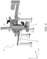
- the labelling station S comprises its own support frame Fs (for example an aluminum structure), which is apt to be laid (and possibly fixedly constrained) on the support structure 9 and supports all the principal components, such as the above-mentioned labelling machine 3 and movement means of said labelling machine 3, which will be detailed in the following.
- Fs for example an aluminum structure
- the labelling machine 3 is a pneumatic machine which comprises at least one inlet 3in for supplying compressed air, as well as ducts to guide the supplied compressed air and to cause the actuation of an application trigger 3g therewith, wherein the actuation of said application trigger 3g determines the application of the label on the food product A.
- the labelling machine 3 is provided with a label collection area (in which, for example, a suitable label loader is housed, or simply an internal area in which several labels are housed), which can be accessed by acting on a suitable slider, wherein a spring (or in general any other suitable means), which has the function of pushing the labels into the application position, is present inside the slider.
- a cylinder 3cl and a piston 3p which is slidingly movable therein, are present inside the body of the labelling machine 3, wherein said piston is moved by the compressed air and the various positions of the piston correspond to the various operating configurations of the labelling machine 3.
- FIGS. 3A-3D various steps of the operation of the labelling machine 3 are illustrated.
- the operation of the labelling machine 3 is based on the movement of compressed air from a part to other parts of the labelling machine 3.
- the labelling machine 3 When the labelling machine 3 is at rest ( figure 3A ), the compressed air is present inside the body of the machine but not in the cylinder 3cl, while, once the application trigger 3g is actuated, an upper valve 3vu opens (for example thanks to the pressure of the compressed air which is delivered when the trigger is actuated), which allows the air to enter inside the cylinder and to cause the piston to come out ( figure 3B , in which the rod of the piston 3p is in a position which is different with respect to figure 3A ).
- the labelling machine 3 comprises suitable means for the automatic actuation of the application trigger 3g when desired, as will be described in the following.
- the apparatus 1 comprises a processing unit, indicated herein with the reference PU, which is adapted to the automatic control thereof.
- processing unit PU includes any type of computerized unit programmed for the automatic control of the apparatus 1. It can comprise any type of hardware and software means, and the present invention is not limited to the specific architecture of the processing unit PU.
- the processing unit PU can comprise a single computerized unit (for example, but not limited to, a single unit for each station, or a single unit for all the apparatus), as well as two or more computerized units associated with different components and in operative communication with each other. It is also possible the presence of one or more local units and one or more remote units.
- the computerized unit PU can comprise one or more physically separated unit, as well as one or more units integrated in other components or instruments, without limiting the scope of the present invention (for example there may be a central unit configured to communicate with calculation means of various instruments, and the like). It is thus clear that various architectures can be implemented, what matters is that there are means suitably programmed for the automatic control of the apparatus 1, according to the techniques illustrated herein.
- the apparatus 1 comprises a vision system 4 configured to perform optical measurements on the food product A moved by the movement system 2.
- Figure 4 shows a schematic perspective view of the vision system 4 associable with the movement system 2.
- said vision system 4 is mounted to its own support frame 4f, for example an aluminum structure, so as to surmount the conveyor belt 2.
- the support frame 4f is provided with fixation feet 4p which can be fixed to the support structure 9.
- the vision system 4 comprises a laser source 41 configured to irradiate, by a laser light, the food product A which is on the movement system 2.
- the laser source can be a diode laser configured to emit light in the wavelength range from 400 nm to 500 nm, however without being limited to particular values since the wavelength can be suitably adapted based on the needs and/or circumstances.
- HeNe laser which emits light with a wavelength of 632.8 nm.
- the vision system 4 operates based on a method without contact, by performing the scanning of the illuminated surface of the food product A and measuring the distance of each point thereof from a reference, so as to reconstruct the profile of the object with high precision and provide fast and accurate measurements of the surface topography of the food product A on which the label is to be applied.
- the vision system 4 is thus substantially an optical profilometer configured to provide information about the food product A moved by the movement system 2 towards the labelling machine 3 (for example information about coordinates of some points thereof or other spatial information).
- the vision system 4 comprises first optical means 4o' configured to shape the light emitted by the laser source 41 towards the food product A in such a way that said light is substantially in the shape of a strip, wherein said irradiated light extends in a direction which is substantially transversal with respect to the travel direction D, as schematically illustrated in figure 5B .
- the first optical means 4o' are not limited by particular components and can comprise for example a particular combination of lenses. In this way, it is possible to linearly expand the laser light emitted towards the food product A.
- the apparatus 1 thus comprise a device for full-field measurements of free surfaces, thanks to the first optical means 4o' which, when placed between the laser source 41 and the food product A which is examined, create a light plane projected on the surface to be scanned so as to capture an entire line and not single points. Thanks to this solution, there is an increase in performances of the system in terms of cost-effectiveness and acquisition times of complex shapes.
- the spatial characteristics of the emitted radiation are not limited to a particular type.
- the characteristics of the laser source and of the emitted beam are selected according to the specific application (for example according to the entity of the measurement and the surface characteristics of the object to be analyzed).
- the labelling machine 3 applies the label at a precise point of the food product A, such as for example the gill of a fish so as to reduce the possibility to have blood drops on the product, and the apparatus 1 is suitably configured to do this, as it will be disclosed in the following.
- the laser source 41 emits laser light towards the target food product A.
- a detector 4d configured to detect the light reflected from the food product A which was irradiated by the laser light.
- the detector 4d is not limited to a particular type; by way of example, it can be a CCD (acronym for "Charge-Coupled Device"), or a CMOS detector, as well as any other type of detector adapted to receive the light radiation reflected by the food product A and by areas which are adjacent thereto.
- the vision system 4 also comprises second optical means 4o", such as for example one or more lenses which are possibly combined with suitable mirrors, configured to convey the reflected light towards the detector 4d in the most suitable way.
- second optical means 4o such as for example one or more lenses which are possibly combined with suitable mirrors, configured to convey the reflected light towards the detector 4d in the most suitable way.
- the relative position between the laser source 41 and the detector 4d is known, and by defining a known reference distance d (for example the distance between the laser source 41 and the conveyor belt 2), it is possible to determine, based on the reflected light, the spatial position (that is the coordinates) of one or more desired points of the object on which the light beam is incident and is reflected, substantially making a triangulation.
- the reflected light is incident on the detector 4d passing through the second optical means 4o".
- the spatial difference between target surfaces (schematically indicated as 4s1, 4s2 and 4s3, which represent in a schematic way and for illustrative purposes only a case in which the product is arranged on the conveyor belt), along the axis z results in a spatial difference of the light which is incident on the detector 4d, thus allowing the above-mentioned evaluation, for example by means of suitable calculation means which process the information coming from the detector 4d.
- the vision system 4 is configured to calculate the coordinates of a point, for example the centroid, of the food product A, as it will be illustrated in the following.
- the optical techniques guarantee high performances and non-invasive measurements. It is in fact known that the measurement precision is influenced by various factors, such as for example target surfaces which are too much reflecting, color differences and color variations. These influences are minimized or completely compensated by the vision system 4 used in the apparatus 1 of the present invention.
- the apparatus 1 is configured to calculate, based on the above-mentioned optical measurements, information (identified herein with the reference I) about the coordinates of one or more specific points (identified herein with the reference P) of the food product A.
- the vision system 4 comprises calculation means 4c configured to produce (calculate), based on the optical measurements performed by the above-illustrated components, the information I about the coordinates of the centroid (or more in general of a given point) of the food product A.
- Said calculation means 4c are in fact configured to perform specific steps of a software in order to calculate a point (for example the centroid) based on the obtained optical data.
- the processing unit PU is then configured to operatively communicate with said calculation means 4c (for example to receive the information I) and estimate with excellent precision, for example based on the coordinates of the centroid given by the calculation means, the coordinates of the specific point of the food product A in which the label is to be applied (such as for example the gill of the fish), for example based on further information previously stored in said processing unit PU (for example, in the case of a fish, the gill is at a known set distance from the centroid, which is used in the apparatus 1 to apply the label in the correct way).
- the calculation means 4c are electrically connected to the detector 4d and are apt to calculate, thanks to suitable algorithms executed by a processor of said calculation means 4c, the coordinates of the centroid of the food product A and to provide them to the processing unit PU. From this centroid, it is then possible to calculate the coordinates of the point P in which the label is to be applied, as described above.
- the information I for example the coordinates of the centroid, possibly together with other information - as seen above
- the processing unit PU comprises at least one programmable logic controller (indicated with the acronym PLC) which receives the information I from the calculation means 4c of the vision system 4 and controls the movement and actuation of the labelling machine 3, even if, as previously mentioned, the present invention is not limited by the used architecture.
- PLC programmable logic controller
- the output of the detector is directly used by a central processing unit which directly calculates the specific point P (i.e., adopting a different point of view - which however is not influencing the scope of the present invention - the calculation means apt to calculate the coordinates of the point P can be considered as part of the processing unit PU, which, as previously observed, may comprise a single unit or multiple units separated from each other, also integrated in different instruments but in operative communication with each other), as well as other architectures; what matters is that there are means to generate the information I based on the optical measurements and means which are adapted to use said information I in a suitable way.
- the present invention is not limited to the example of the fish and said teachings can be applied to any element to be labelled, as well as to any specific point in which the label is to be applied.
- the used profilometer which operates without contacting the surface of the food product A, allows very fast measurements, since the scanning velocity depends only on the reflection velocity of the light on the surface and on the acquisition velocity of the electronics. It is also very reliable because, since it is not touching the surface of the food product A, it cannot damage it in any way. Furthermore, these instruments require little maintenance. It is also observed that the dimensions of the laser beam, or lateral resolution, are in a range of a few micrometers to less than one micrometer, thus providing very precise measurements. It is thus evident that the introduction of the vision system 4 inside the apparatus 1 and the communication thereof with the other components of the apparatus results in considerable advantages in the optimization and automation process of said apparatus 1, thus allowing to obtain the desired information in the most suitable way.
- the processing unit PU is configured to control the operation of the labelling machine 3 such that said labelling machine 3 automatically applies the label at said specific point P of the food product A based on said information I, as will it be detailed in the following.
- the apparatus 1 comprises, at the labelling station S, movement means configured to move the labelling machine 3 along three directions which are substantially coincident with the three Cartesian axes (i.e., according the above-mentioned directions x, y and z), wherein, according to the reference of figures, the direction y substantially coincides with the travel direction D of the food product A on the conveyor belt 2 and the direction z is substantially coincident with the vertical direction.
- the movement means configured to move the labelling machine 3 in the direction x are identified with the reference 5x
- the movement means configured to move the labelling machine 3 in the direction y are identified with the reference 5y
- the movement means configured to move the labelling machine 3 in the direction z are identified with the reference 5z.
- the movement of the labelling machine 3 in the directions x, y and z is thus guaranteed by suitable movement means.
- the movement means 5 are linear actuator which are apt to convert the rotary motion of a motor in a linear movement, exerting a force on a single axis.
- a linear actuator can comprise an electric motor, a toothed belt and a movable sledge.
- the present disclosure can provide a combination of various linear actuators (in general, of various movement means), in particular three linear actuators, joined to each other by suitable supports for example along orthogonal directions, in order to allow the movement of the labelling machine 3 in the three directions.
- various linear actuators in general, of various movement means
- three linear actuators joined to each other by suitable supports for example along orthogonal directions, in order to allow the movement of the labelling machine 3 in the three directions.
- the information I are used by the processing unit PU to control the operation of the labelling machine 3, for example to control the movement thereof by means of the above-mentioned movement means, and to control the actuation of the trigger 3g over time, such that the label is applied in a precise way in the point P, for example at the gill of the fish while it passes on the conveyor belt 2.
- the relative distance between the vision system 4 and the labelling machine 3 (which is a known distance, for example when the labelling machine 3 is in a reference position, such as for example a rest position or at the end of the stroke of the movement means) is used to calculate, by the processing unit PU, the moment in which said labelling machine 3 can apply the label in the point P, in particular by applying the known motion laws.
- the processing unit PU is further configured to move the labelling machine 3 at least along the travel direction D (that is along the axis y of the reference system of the figures) and to control the application of the label at the specific point P of the food product A when the relative velocity between said food product A and the labelling machine 3 along the travel direction D is substantially zero.
- the labelling machine 3 in order to apply the label, is moved both along z in order to reach the surface of the food product A, and along y in order to adjust the velocity thereof; it is not necessary to move it also along x, even if it can be done to obtain an even finer adjustment.
- the processing unit PU is configured to substantially perform a tracking of the point P of the food product A in which it is desired to apply the label, while said product is moved by the conveyor belt 2. Based on said control, the processing unit PU is thus apt to command the application of the label in said point P, in particular when the relative velocity between the food product A (in particular the point P) and the labelling machine 3 is substantially zero, so as to apply the label in the most suitable way.
- the processing unit PU is configured to command a movement to the labelling machine 3 based on an acceleration ramp applied to the movement means thereof at least along the travel direction D; for example, a tension ramp that causes the actuation of the linear actuator 5y and the resulting acceleration of the labelling machine 3 is provided.
- the processing unit PU is then configured to calculate, based on said provided acceleration ramp (for example by using the known motion laws), the position along the travel direction D in which the food product A and the labelling machine 3 have a same velocity, and thus in which the label is to be applied.
- the processing unit PU is thus able to calculate the point in which the food product A and the labelling machine 3 have a same velocity along y, and thus the point (and consequently also the moment) in which the label is to be applied.
- the labelling machine 3 is moved only along the axis y in order to obtain said velocity coincidence, however nothing prevents from moving said labeling machine 3 also along x for a finer adjustment of the application of the label.
- the labelling machine 3 is moved also along z, for example based on height information provided by the vision system 4 (which is in fact also adapted to calculate the thickness of the food product A).
- the processing unit PU is configured to control the movement of the labelling machine 3 at least along y and z, and possibly also along x, according to the needs; in particular, in order to perform the above-mentioned tracking of the coordinates of the point P, in addition to z (which is performed for the application of the label in the point P regardless of the tracking), the labelling machine 3 is able also to move, under the control of the processing unit PU, at least along y, in order to assume a velocity which is substantially coincident with the travel velocity of the food product A along the direction D, and apply the label when the relative velocity is substantially zero/null.
- the implemented tracking system is advantageous since the presence of only the movement means along x and z allows to align the labelling machine 3 in a suitable way, but it is not enough to guarantee the continuity of the system during the application of the labels, since, in order to apply the label, the labelling machine 3 contacts the food product A which, when it moves, would "collide” with the machine if the latter is not moving also along y. In order to avoid this situation and guarantee the continuity, the labelling machine 3 is thus moved also along y, according to the above-described tracking system. In this way, the labelling machine is able to follow the food product and apply the label when both are moving and the relative velocity between them is substantially zero.
- the apparatus 1 comprises a reloading station Sr adapted to automatically reload labels into the labelling machine 3.
- the reloading station Sr comprises suitable means configured to perform the above-mentioned automatic reloading operation of the labelling machine 3.
- the reloading station Sr comprises at least one label store 6, which is operatively connectable with the labelling machine 3, and the processing unit PU is adapted to command the drawing of the labels from the label store 6 and the supply thereof in the labelling machine 3, in particular when the labels in said labelling machine 3 are equal or lower than a determined number, or when they are exhausted.
- the means of the reloading station Sr can be operated after a determined number of applications of labels.
- the movement means 5x are configured to move the labelling machine 3 off-line (that is in the direction x) towards the reloading station Sr for the automatic reloading thereof.
- the reloading station Sr comprises a movement device Src configured to move from a first position, which is closer to the label store 6 and in which it is possible to drawn labels from said label store 6 (for example it is under the label store 6, as in figures 6C and 6D ), to a second position, which is closer to the labelling machine 3 and in which it is possible to load the labels in said labelling machine 3 (for example under the labelling machine 3, as in figure 6A ), and vice versa.
- the movement device Src may be a carriage. It is observed that the term carriage does not limit the shape or the movement of the movement device, but it general relates to a transport device along specific directions.
- the carriage Src is moved by suitable movement means Sm which act on it (and which may be controlled electrically or pneumatically or in any other suitable way), said movement occurring in various space directions both laterally (along y and/or x) and vertically (along z) in order to assume the above-mentioned two positions and to suitably load the labels.
- the carriage Src is shaped so as to comprise a housing space to house the labels coming from the label store 6, and possibly also holding means thereof.
- the label store 6 may have a door for accessing to the label housings; the labels may be inserted into the store in groups (possibly connected to each other) and the reloading station Sr may comprise means (e.g., pistons) configured to be actuated to singularize groups of labels for the insertion thereof into the movement device Src and then into the labeling machine 3.
- means e.g., pistons
- the label store 6 is divided in various compartments 6s (for example vertical compartments) and the movement of the movement device Src (e.g., the carriage) is suitably adjusted in order to automatically select each time its stop position at the desired compartment (for example based on a preset working sequence).
- the movement of the movement device Src e.g., the carriage
- the apparatus 1 comprises at least two labelling stations, indicated as S' and S", which in turn include respective labelling machines 3 and respective reloading systems. Since the respective components are identical in each labelling station S' and S', the same reference number have been used.
- the two labelling stations S' and S" are thus identical and symmetrically mounted.
- the processing unit PU is configured such that, while a labelling station (S' or S") among said at least two stations is operating and the respective labelling machine is operating in order to apply the label on the food product A, the labelling machine in the other labelling station (S" or S') is reloaded by the reloading station Sr, drawing labels from the label store 6 by automatic means.
- the labelling machine 3 is automatically reloaded once it is unloaded and, while a machine is loaded, the other one works so as to guarantee the continuity.
- This allows to have a very long autonomy since the label store 6 can contain several labels (e.g., more than eight thousand labels), guaranteeing an autonomy of around three hours for each station, and thus, in the case of two stations S' and S", an overall autonomy of the apparatus 1 of around six hours.
- the apparatus 1 comprises an additional vision system 7 (for example comprising one or more cameras) configured to capture images and/or videos of the food product A after the label was applied by the labelling machine 3.
- an additional vision system 7 for example comprising one or more cameras
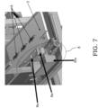
- the apparatus 1 further comprise a reject discharge station 8 configured to receive data from the above-mentioned additional vision system 7.
- the reject discharge station 8 comprises means adapted to deviate the food product A towards a reject store, based on the received data, in case the images and/or videos captured by the additional vision system 7 do not match expected images and/or videos, for example when the label is not detected in a captured image or when it is applied in a wrong position of the food product A.
- the task of the additional vision system 7 is thus mainly to control if the labelling machine 3 applied the label or not.
- a high-resolution camera is not required for this unit, since its base task is only to detect the presence of the label, without having to perform complex imaging operations.
- the additional vision system 7 is supported by an aluminum structure.
- the reject discharge station 8 comprises a selector 8s (for example in the form of a mechanical arm) and an actuator 8a (for example a pneumatic rotary actuator) configured to actuate the selector 8s when desired. More in particular, based on the data received from the additional vision system 7, the selector 8s is activated and conveys the food product A towards a reject store 8m. Also this station is controlled by the processing unit PU, for example by a designated PLC, or by the same PLC which controls the labelling machine 3.
- the processing unit PU for example by a designated PLC, or by the same PLC which controls the labelling machine 3.
- the apparatus 1 is structured in such a way that, at a first position or initial position, a loading area A1 is defined in which the operator places the food product to be labelled, and, at a second position or final position, an unloading area A2 is defined in which the labelled food product is present, which product can then be drawn by the operator or by automatic drawing means.
- the present invention provides an apparatus which is able to automatically apply a label to a food product, such as for example a fish, thanks to an optical measurement of the surface of said food product while it is moved by a conveyor belt, wherein the results of said optical measurement are used by a labelling machine adapted to apply the label at a determined portion of the food product, such as for example the gill of the fish.
- a labelling machine adapted to apply the label at a determined portion of the food product, such as for example the gill of the fish.
- the above-mentioned optical measurement allows to obtain the coordinates of one or more points of the food product in which the label is to be applied.
- the movement of the labelling machine is automatically adjusted such that the label is applied in the desired point when the velocity of the food product and the velocity of said labelling machine substantially coincide, and thus said label is applied (with reference to the travel direction of the food product) in the point in which said velocities coincide.
- each step is automatically controlled, starting from the optical measurement of the surface of the food product up to the application of the label, also including the automatic reloading of the labelling machine once the labels contained therein are exhausted (or nearly exhausted).
- a completely automated apparatus is thus disclosed, which apparatus allows the automatic application of labels to food products such as fish and/or chicken (but not being limited thereto), said apparatus also allowing an automatic reloading of the labels.
- the apparatus is able to apply a label on food products in an automatic, efficient and precise way, in particular in a desired point thereof, without the need of intervention of the operator in any process step.
- the possibility to automatically reload the labelling machine once it exhausted the labels contributes to increase the efficiency and the speed of the process, since the autonomy of the apparatus is increased, and a continuous stop/interruption thereof is avoided.
- the present invention can be simply adapted to already existing apparatuses, providing a structure which can be integrated in existing automatic lines, for examples existing lines having a structural basement and a conveyor belt.
- the apparatus disclosed herein thus solves the technical problem of the present invention, obtaining considerable advantages, such as for example the automation of the labelling process and the increase in the production rate and efficiency. It furthermore drastically reduces the risk of injury for the operator, which has only the task of arranging the loaders (which may simply be a plurality of labels packed together) at the beginning of the day and possibly of managing, with the due distances and protections, rare operating errors of the apparatus. The operator, completely safe, simply supervises the proper operation of the apparatus.
- the vision system which is integrated in the apparatus for example by a portal structure, allows to accurately apply the label in a desired point of the food product, which is very advantageous and allows to reduce the rejects and, in the case of fish, avoid blood drops which may result from an inaccurate labelling manually made by the operator.
Landscapes
- Labeling Devices (AREA)
- General Preparation And Processing Of Foods (AREA)
- Confectionery (AREA)
- Control And Other Processes For Unpacking Of Materials (AREA)
- Supplying Of Containers To The Packaging Station (AREA)
Abstract
Description
- The present invention refers to an apparatus for labelling food products, such as for example labelling of fish or chicken. The following description is made with reference to this application field with the only purpose of simplifying the exposition thereof.
- As it is well known in this specific technical field, labels are applied to food products in order to identify a product and provide information about it. By way of example, the label can show the trademark associated with the food product and information about the composition or organoleptic values of said food product, as well as characteristics such as the production date, the production batch and the like.
- Pneumatic apparatuses (also called labelling machines) for manually applying labels in specific points of a food product are known. In these manual solutions, the food product to be labelled is moved by a conveyor belt, while one or more operators located at the sides of said conveyor belt apply the labels by means of the above-mentioned manual labelling machines.
- The above-described known solutions are limited by the skills of the operator, both regarding the execution times and regarding the execution quality. Furthermore, these known solutions are very monotonous and also hard for the operators, since the labelling machines can have a weight of about 2 Kg or higher, which can create inconveniences when this operation is carried out for a prolonged amount of time.
- Furthermore, the known solutions have a limited autonomy. In fact, the labelling machines generally have an application capacity of around two hundred labels, after which it necessary to reload them. Since, generally, a production line is designated to process around three thousand pieces per hour, a labelling machine should be reloaded fifteen times per hour, that is there is an autonomy of only four minutes and thus, in the known solution, the operator must continuously repeat the reloading operation.
- There is thus the need in the field for an apparatus which allows to apply a label to a food product in an automatic and efficient way, thereby optimizing the rate of said operation, its regularity, its efficiency, and its costs.
- The technical problem of the present invention is to devise an apparatus for applying labels to food products having structural and functional features so as to allow to overcome the limits and drawbacks of the known solutions, in particular which is able to apply a label automatically and efficiently at a determined point of the food product.
- The solution idea underlying the present invention is to provide an apparatus which is able to automatically apply a label to a food product, such as for example a fish, thanks to an optical measurement of the surface of said food product while it is moved by a conveyor belt, wherein the results of said optical measurement are used by a labelling machine adapted to apply the label at a determined portion of the food product, such as for example the gill of the fish. Specifically, the above-mentioned optical measurement allows to obtain the coordinates of one or more points of the food product in which the label is to be applied. In order to apply the label in the most suitable way, the movement of the labelling machine is automatically adjusted such that the label is applied in the desired point when the velocity of the food product and the velocity of said labelling machine substantially coincide, and thus said label is applied (with reference to the travel direction of the food product) in the point in which said velocities coincide. In this way, each step is automatically controlled, starting from the optical measurement of the surface of the food product up to the application of the label, also including the automatic reloading of the labelling machine once the labels contained therein are exhausted (or nearly exhausted).
- Based on this solution idea, the above-mentioned technical problem is solved by an apparatus for applying labels on food products, comprising a processing unit adapted to automatically control the apparatus, a movement system adapted to move a food product according to a travel direction, a labelling machine configured to automatically apply a label on the food product moved by the movement system, and a vision system configured to perform optical measurements on the food product moved by the movement system, the apparatus being configured to calculate, based on said optical measurements, information about the coordinates of one or more specific points of the food product, wherein the processing unit is configured to control the operation of the labelling machine in such a way that it applies (is apt to apply) the label at said one or more specific points based in said information (in particular when the food product is at said labelling machine), and wherein the processing unit is further configured to move the labelling machine at least along the travel direction and to control the application of the label at the specific point of the food product when the relative velocity between said food product, in particular between said specific point of the food product, and said labelling machine along the travel direction is substantially zero.
- In other words, the processing unit is substantially configured to carry out the tracking of the specific point of the food product when it is moved by the movement system, said tracking being carried out by moving the labelling machine, so as to command the application of the label in said specific point when the labeling machine reached the position (in particular along the travel direction), wherein the relative velocity between said food product and said labelling machine is substantially zero, that is when they substantially have the same velocity.
- Advantageously according to the invention, the apparatus comprises a reloading station adapted to automatically reload labels into the labelling machine, wherein said reloading station comprises at least one label store (which is operatively connected with the labelling machine), and wherein the processing unit is configured to command the drawing of labels from the label store and the supply of said drawn labels into the labelling machine when the labels in said labelling machine are equal or less than a given number, or when they are exhausted, for example after applying a given number of labels.
- The apparatus further comprises movement means configured at least to move the labelling machine off-line towards the reloading station for the automatic reloading thereof, wherein the reloading station comprises a movement device, such as for example a carriage, configured to move from a first position, which is closer to the label store than to the labelling machine, and in which it is possible to draw labels from the label store (that is, the carriage is configured to carry out the drawing operation), to a second position, which is closer to the labelling machine than to the label store and in which it is possible to load the labels into said labelling machine (that is the carriage is configured to carry out the loading operation), and vice versa.
- The above-mentioned movement device (e.g., the carriage) thus allows the operating connection between the labelling machine and the label store and is comprised in the means configured to carry out the automatic reloading by the reloading station, said movement device being able to perform various suitable movements according to various directions.
- More particularly, the invention comprises the following additional and optional features, taken singularly or in combination if needed.
- According to an aspect of the present invention, the apparatus can comprise at least two labelling stations which include respective labelling machines and respective reloading stations, the processing unit being configured such that, while a labelling station of said at least two labelling stations is operating and the respective labelling machine is operating to apply the label on the food product, the labelling machine in the other labelling station of said at least two labelling stations is reloaded by the respective reloading station, and vice versa.
- According to an aspect of the present invention, the vision system can comprise a laser source configured to irradiate by a laser light the food product on the movement system, a detector configured to detect light reflected by the food product irradiated by the laser light, first optical means configured to shape the light irradiated from the laser source towards the food product in such a way that said light is substantially in the shape of a strip (that is, configured to expand said light in a linear shape), wherein the irradiated light extends (expands) in a substantially transversal direction with respect to the travel direction, and, second optical means configured to convey the reflected light towards the detector.
- According to an aspect of the present invention, the apparatus can comprise means configured to move the labelling machine along three directions which are substantially coincident with the three cartesian axes, wherein one direction of said three directions is the direction substantially coinciding with the travel direction of the food product on the movement system. The processing unit can be thus configured to control the movement of the labelling machine along said three directions.
- According to an aspect of the present invention, the processing unit can be configured to command a movement to the labelling machine based on an acceleration ramp along the travel direction. The processing unit can be thus configured to calculate, based on said acceleration ramp, the position along the travel direction in which the food product and the labelling machine have the same velocity.
- According to an aspect of the present invention, the labelling machine can be a pneumatic labelling machine comprising at least one inlet for supplying compressed air and ducts to guide the supplied compressed air and to cause the actuation of an application trigger, wherein the actuation of the application trigger determines the application of the label on the food product.
- According to an aspect of the present invention, the apparatus can further comprise an additional vision system configured to capture images and/or videos of the food product following the application of the label by the labelling machine.
- According to an aspect of the present invention, the apparatus can comprise a reject discharge station configured to receive data from the additional vision system, said reject discharge station comprising means adapted to deviate and collect the food product, based on the received data, in case the images and/or videos captured by the additional vision system do not match expected images and/or videos, for example when the label is not detected.
- According to an aspect of the present invention, the movement system can be a conveyor belt which passes through at least the vision system and the labelling machine, for example between a loading area and an unloading area.
- According to an aspect of the present invention, the processing unit can comprise at least one programmable logic controller.
- According to an aspect of the present invention, the vision system can comprise calculation means configured to calculate the coordinates of the centroid of the food product, and the processing unit (which is in communication with said calculation means) can be configured to calculate (estimate) the specific point of the food product based on said coordinates of the centroid provided by the vision system.
- The characteristics and advantages of the apparatus according to the invention will be apparent from the description, made hereinafter, of an embodiment thereof, given by way of indicative and non-limiting example, with reference to the enclosed drawings.
- In the drawings:
-
figure 1 is a perspective view of an apparatus according to the present invention; -
figure 2 shows a detail of a labelling station comprising a labelling machine in an embodiment of the present invention; -
figures 3A-3D show a labelling machine in different operating steps; -
figure 4 is a schematic perspective view of a vision system of the apparatus of the present invention; -
figures 5A-5B show details of the vision system according to an embodiment of the present invention; -
figures 6A-6D show different views of a reloading station of the apparatus according to the present invention; and -
figure 7 shows a detail of the apparatus of the present invention, wherein a reject discharge station is visible. - With reference to those figures, an apparatus according to the present invention is globally and schematically indicated with 1.
- It is worth noting that the figures represent schematic views and are not drawn to scale, but instead they are drawn so as to emphasize the important features of the invention. Moreover, in the figures, the different elements are depicted in a schematic manner, and their shape may vary depending on the application desired. It is also noted that, in the figures, the same reference numbers refer to elements that are identical in shape or function. Finally, particular features described in relation to an embodiment illustrated in a figure are also applicable to the other embodiments illustrated in the other figures.
- It is also observed that, when sequences of process steps are illustrated, said steps do not necessarily follow the indicated sequence, and said steps can be, in some cases, inverted.
- The
apparatus 1 of the present invention is preferably used to apply a label on food products, which are identified herein with the reference A, in particular in a determined desired portion of said food products A. By way of a non-limiting example, theapparatus 1 can be used to apply labels to fish (for example at the gill of the fish), or to fresh poultry, as it will be illustrated in the following. However, it is noted that theapparatus 1 can be also used with other types of products. The examples shown in the following description are only illustrative and are in no way limiting the scope of the present invention. - It is also observed that, in the present description, the term "label" means any type of element which can be applied to the food product in order to display various information, without being limited to a particular form and/or material. In the context of the present invention, the term "label" can also be substituted by the term "seal", without varying the scope of the invention.
- As illustrated in
figure 1 , theapparatus 1 comprises amovement system 2 apt to move the food product A according to a travel direction, which is identified herein with the reference D and is substantially coincident with the direction y of the Cartesian reference system of the figures. Themovement system 2 is preferably a conveyor belt (as known in the field), and, in the following description, the terms "movement system" and "conveyor belt" can be understood as synonyms. Theconveyor belt 2 can be supported by a support structure 9 apt to support all components of theapparatus 1. - The
conveyor belt 2 passes through different stations of theapparatus 1, as will be detailed in the following. In other words, theapparatus 1 comprises multiple stations which are apt to perform various tasks in sequence in order to achieve the set goal. - As illustrated in
figure 1 and as will be detailed in the following, theapparatus 1 comprises two labelling stations, which are indicated as S' and S", even if the present invention is not limited to two labelling stations and any number thereof can be used, starting from a single labelling station. - Referring now to
figure 2 , the labelling station S (and, in case of several labelling stations, this is valid for each of them) includes alabelling machine 3 configured to automatically apply a label to the food product A moved by themovement system 2. - The labelling station S comprises its own support frame Fs (for example an aluminum structure), which is apt to be laid (and possibly fixedly constrained) on the support structure 9 and supports all the principal components, such as the above-mentioned
labelling machine 3 and movement means of saidlabelling machine 3, which will be detailed in the following. - In an embodiment of the present invention, the
labelling machine 3 is a pneumatic machine which comprises at least one inlet 3in for supplying compressed air, as well as ducts to guide the supplied compressed air and to cause the actuation of anapplication trigger 3g therewith, wherein the actuation of saidapplication trigger 3g determines the application of the label on the food product A. Thelabelling machine 3 is provided with a label collection area (in which, for example, a suitable label loader is housed, or simply an internal area in which several labels are housed), which can be accessed by acting on a suitable slider, wherein a spring (or in general any other suitable means), which has the function of pushing the labels into the application position, is present inside the slider. Furthermore, as known in the art, a cylinder 3cl and apiston 3p, which is slidingly movable therein, are present inside the body of thelabelling machine 3, wherein said piston is moved by the compressed air and the various positions of the piston correspond to the various operating configurations of thelabelling machine 3. - Particularly referring to
figures 3A-3D , various steps of the operation of thelabelling machine 3 are illustrated. In particular, as previously mentioned, the operation of thelabelling machine 3 is based on the movement of compressed air from a part to other parts of thelabelling machine 3. When thelabelling machine 3 is at rest (figure 3A ), the compressed air is present inside the body of the machine but not in the cylinder 3cl, while, once theapplication trigger 3g is actuated, an upper valve 3vu opens (for example thanks to the pressure of the compressed air which is delivered when the trigger is actuated), which allows the air to enter inside the cylinder and to cause the piston to come out (figure 3B , in which the rod of thepiston 3p is in a position which is different with respect tofigure 3A ). Once the piston reaches the end of the stroke (figure 3C ), the air begins to flow in a return chamber 3c thanks to some holes which are present on the cylinder 3cl. Finally, when theapplication trigger 3g is released (figure 3D ), the air present in the return chamber 3c allows thepiston 3p to return in its rest position and, since the upper valve 3vu remains closed, the air remained in the cylinder exits from adischarge 3s, thus completing the cycle. Thelabelling machine 3 comprises suitable means for the automatic actuation of theapplication trigger 3g when desired, as will be described in the following. - The
apparatus 1 comprises a processing unit, indicated herein with the reference PU, which is adapted to the automatic control thereof. It is observed that, in the context of the present invention, the term "processing unit PU" includes any type of computerized unit programmed for the automatic control of theapparatus 1. It can comprise any type of hardware and software means, and the present invention is not limited to the specific architecture of the processing unit PU. For example, the processing unit PU can comprise a single computerized unit (for example, but not limited to, a single unit for each station, or a single unit for all the apparatus), as well as two or more computerized units associated with different components and in operative communication with each other. It is also possible the presence of one or more local units and one or more remote units. Furthermore, the computerized unit PU can comprise one or more physically separated unit, as well as one or more units integrated in other components or instruments, without limiting the scope of the present invention (for example there may be a central unit configured to communicate with calculation means of various instruments, and the like). It is thus clear that various architectures can be implemented, what matters is that there are means suitably programmed for the automatic control of theapparatus 1, according to the techniques illustrated herein. - Suitably, the
apparatus 1 comprises avision system 4 configured to perform optical measurements on the food product A moved by themovement system 2.Figure 4 shows a schematic perspective view of thevision system 4 associable with themovement system 2. - In order to associate the
vision system 4 with theconveyor belt 2, saidvision system 4 is mounted to itsown support frame 4f, for example an aluminum structure, so as to surmount theconveyor belt 2. Thesupport frame 4f is provided withfixation feet 4p which can be fixed to the support structure 9. - In an embodiment of the present invention, schematically illustrated in
figures 5A-5B , thevision system 4 comprises alaser source 41 configured to irradiate, by a laser light, the food product A which is on themovement system 2. - By way of example, the laser source can be a diode laser configured to emit light in the wavelength range from 400 nm to 500 nm, however without being limited to particular values since the wavelength can be suitably adapted based on the needs and/or circumstances.
- In some configurations, it is also possible to use a HeNe laser which emits light with a wavelength of 632.8 nm.
- The
vision system 4 operates based on a method without contact, by performing the scanning of the illuminated surface of the food product A and measuring the distance of each point thereof from a reference, so as to reconstruct the profile of the object with high precision and provide fast and accurate measurements of the surface topography of the food product A on which the label is to be applied. Thevision system 4 is thus substantially an optical profilometer configured to provide information about the food product A moved by themovement system 2 towards the labelling machine 3 (for example information about coordinates of some points thereof or other spatial information). - In an embodiment of the present invention, the
vision system 4 comprises first optical means 4o' configured to shape the light emitted by thelaser source 41 towards the food product A in such a way that said light is substantially in the shape of a strip, wherein said irradiated light extends in a direction which is substantially transversal with respect to the travel direction D, as schematically illustrated infigure 5B . The first optical means 4o' are not limited by particular components and can comprise for example a particular combination of lenses. In this way, it is possible to linearly expand the laser light emitted towards the food product A. Theapparatus 1 thus comprise a device for full-field measurements of free surfaces, thanks to the first optical means 4o' which, when placed between thelaser source 41 and the food product A which is examined, create a light plane projected on the surface to be scanned so as to capture an entire line and not single points. Thanks to this solution, there is an increase in performances of the system in terms of cost-effectiveness and acquisition times of complex shapes. - Even though the above embodiment is considered to be the preferred one, the spatial characteristics of the emitted radiation are not limited to a particular type. By way of example, it is possible to use a laser beam focalized into a light spot, thereby providing devices for punctual measurements. In general, the characteristics of the laser source and of the emitted beam are selected according to the specific application (for example according to the entity of the measurement and the surface characteristics of the object to be analyzed).
- It is also possible to use structured white light to be emitted towards the food product A, in some embodiments.
- In any case, it is desirable that the
labelling machine 3 applies the label at a precise point of the food product A, such as for example the gill of a fish so as to reduce the possibility to have blood drops on the product, and theapparatus 1 is suitably configured to do this, as it will be disclosed in the following. - As indicated in
figures 5A-5B and as previously seen, thelaser source 41 emits laser light towards the target food product A. Then there is adetector 4d configured to detect the light reflected from the food product A which was irradiated by the laser light. Thedetector 4d is not limited to a particular type; by way of example, it can be a CCD (acronym for "Charge-Coupled Device"), or a CMOS detector, as well as any other type of detector adapted to receive the light radiation reflected by the food product A and by areas which are adjacent thereto. - The
vision system 4 also comprises second optical means 4o", such as for example one or more lenses which are possibly combined with suitable mirrors, configured to convey the reflected light towards thedetector 4d in the most suitable way. - In an embodiment, since the relative position between the
laser source 41 and thedetector 4d is known, and by defining a known reference distance d (for example the distance between thelaser source 41 and the conveyor belt 2), it is possible to determine, based on the reflected light, the spatial position (that is the coordinates) of one or more desired points of the object on which the light beam is incident and is reflected, substantially making a triangulation. - As illustrated in the figures, the reflected light is incident on the
detector 4d passing through the second optical means 4o". In this case, the spatial difference between target surfaces (schematically indicated as 4s1, 4s2 and 4s3, which represent in a schematic way and for illustrative purposes only a case in which the product is arranged on the conveyor belt), along the axis z results in a spatial difference of the light which is incident on thedetector 4d, thus allowing the above-mentioned evaluation, for example by means of suitable calculation means which process the information coming from thedetector 4d. - Obviously, also other evaluation modes fall within the scope of the present invention, what matters is that the
vision system 4 is configured to calculate the coordinates of a point, for example the centroid, of the food product A, as it will be illustrated in the following. - In general, the optical techniques guarantee high performances and non-invasive measurements. It is in fact known that the measurement precision is influenced by various factors, such as for example target surfaces which are too much reflecting, color differences and color variations. These influences are minimized or completely compensated by the
vision system 4 used in theapparatus 1 of the present invention. - The
apparatus 1 is configured to calculate, based on the above-mentioned optical measurements, information (identified herein with the reference I) about the coordinates of one or more specific points (identified herein with the reference P) of the food product A. - In particular, in an embodiment, the
vision system 4 comprises calculation means 4c configured to produce (calculate), based on the optical measurements performed by the above-illustrated components, the information I about the coordinates of the centroid (or more in general of a given point) of the food product A. Said calculation means 4c are in fact configured to perform specific steps of a software in order to calculate a point (for example the centroid) based on the obtained optical data. - The processing unit PU is then configured to operatively communicate with said calculation means 4c (for example to receive the information I) and estimate with excellent precision, for example based on the coordinates of the centroid given by the calculation means, the coordinates of the specific point of the food product A in which the label is to be applied (such as for example the gill of the fish), for example based on further information previously stored in said processing unit PU (for example, in the case of a fish, the gill is at a known set distance from the centroid, which is used in the
apparatus 1 to apply the label in the correct way). Obviously, in other applications or in other embodiments, it is also possible to apply the label directly at the centroid, or possibly also in other points. - Accordingly, according to particular embodiment, the calculation means 4c are electrically connected to the
detector 4d and are apt to calculate, thanks to suitable algorithms executed by a processor of said calculation means 4c, the coordinates of the centroid of the food product A and to provide them to the processing unit PU. From this centroid, it is then possible to calculate the coordinates of the point P in which the label is to be applied, as described above. - In other words, knowing the coordinates of the centroid of the food product A (or any other point whose coordinates can be calculated as described above), it is possible to known the point P in which the label is to be applied (which can be the centroid itself or another point having a generally known distance from it), and thus the processing unit PU is adapted to use the information I (for example the coordinates of the centroid, possibly together with other information - as seen above) to define proper control instructions (for example movement and timing control) of the
labelling machine 3. - In an embodiment, the processing unit PU comprises at least one programmable logic controller (indicated with the acronym PLC) which receives the information I from the calculation means 4c of the
vision system 4 and controls the movement and actuation of thelabelling machine 3, even if, as previously mentioned, the present invention is not limited by the used architecture. Furthermore, again referring tofigure 4 , all the components of thevision system 4, that is the optics and the calculation means, can be comprised in a casing or body 4' supported by thesupport frame 4f. - Obviously, also other embodiments are possible in which the output of the detector is directly used by a central processing unit which directly calculates the specific point P (i.e., adopting a different point of view - which however is not influencing the scope of the present invention - the calculation means apt to calculate the coordinates of the point P can be considered as part of the processing unit PU, which, as previously observed, may comprise a single unit or multiple units separated from each other, also integrated in different instruments but in operative communication with each other), as well as other architectures; what matters is that there are means to generate the information I based on the optical measurements and means which are adapted to use said information I in a suitable way. Furthermore, the present invention is not limited to the example of the fish and said teachings can be applied to any element to be labelled, as well as to any specific point in which the label is to be applied.
- The used profilometer, which operates without contacting the surface of the food product A, allows very fast measurements, since the scanning velocity depends only on the reflection velocity of the light on the surface and on the acquisition velocity of the electronics. It is also very reliable because, since it is not touching the surface of the food product A, it cannot damage it in any way. Furthermore, these instruments require little maintenance. It is also observed that the dimensions of the laser beam, or lateral resolution, are in a range of a few micrometers to less than one micrometer, thus providing very precise measurements. It is thus evident that the introduction of the
vision system 4 inside theapparatus 1 and the communication thereof with the other components of the apparatus results in considerable advantages in the optimization and automation process of saidapparatus 1, thus allowing to obtain the desired information in the most suitable way. - Suitably, the processing unit PU is configured to control the operation of the
labelling machine 3 such that saidlabelling machine 3 automatically applies the label at said specific point P of the food product A based on said information I, as will it be detailed in the following. - Furthermore, in an embodiment, the
apparatus 1 comprises, at the labelling station S, movement means configured to move thelabelling machine 3 along three directions which are substantially coincident with the three Cartesian axes (i.e., according the above-mentioned directions x, y and z), wherein, according to the reference of figures, the direction y substantially coincides with the travel direction D of the food product A on theconveyor belt 2 and the direction z is substantially coincident with the vertical direction. The movement means configured to move thelabelling machine 3 in the direction x are identified with thereference 5x, the movement means configured to move thelabelling machine 3 in the direction y are identified with thereference 5y, and the movement means configured to move thelabelling machine 3 in the direction z (that is the vertical direction) are identified with thereference 5z. The movement of thelabelling machine 3 in the directions x, y and z is thus guaranteed by suitable movement means. - In a preferred, but not limiting, embodiment of the present invention, the movement means 5 are linear actuator which are apt to convert the rotary motion of a motor in a linear movement, exerting a force on a single axis. For example, as known in the field, a linear actuator can comprise an electric motor, a toothed belt and a movable sledge.
- Obviously, also other movement means can be used according to other embodiments of the present invention.
- The present disclosure can provide a combination of various linear actuators (in general, of various movement means), in particular three linear actuators, joined to each other by suitable supports for example along orthogonal directions, in order to allow the movement of the
labelling machine 3 in the three directions. - As mentioned above, the information I are used by the processing unit PU to control the operation of the
labelling machine 3, for example to control the movement thereof by means of the above-mentioned movement means, and to control the actuation of thetrigger 3g over time, such that the label is applied in a precise way in the point P, for example at the gill of the fish while it passes on theconveyor belt 2. - In this way, once the operator places the food product A on the
conveyor belt 2, it passes through thevision system 4 and thelabelling machine 3, which operate in an automatic and innovative way. - Thanks to the coordinates of the point P, which may be calculated as disclosed above, and by knowing suitable spatial references between the
vision system 4 and thelabelling machine 3, it is possible to control the latter by means of the processing unit PU such that the label is automatically applied exactly in that point P. - More in particular, in an embodiment of the present invention, once the coordinates of the point P are estimated, the relative distance between the
vision system 4 and the labelling machine 3 (which is a known distance, for example when thelabelling machine 3 is in a reference position, such as for example a rest position or at the end of the stroke of the movement means) is used to calculate, by the processing unit PU, the moment in which saidlabelling machine 3 can apply the label in the point P, in particular by applying the known motion laws. - As it will be detailed in the following, in order to obtain an optimal labelling process, the processing unit PU is further configured to move the
labelling machine 3 at least along the travel direction D (that is along the axis y of the reference system of the figures) and to control the application of the label at the specific point P of the food product A when the relative velocity between said food product A and thelabelling machine 3 along the travel direction D is substantially zero. - In this way, in an embodiment, in order to apply the label, the
labelling machine 3 is moved both along z in order to reach the surface of the food product A, and along y in order to adjust the velocity thereof; it is not necessary to move it also along x, even if it can be done to obtain an even finer adjustment. - In particular, the processing unit PU is configured to substantially perform a tracking of the point P of the food product A in which it is desired to apply the label, while said product is moved by the
conveyor belt 2. Based on said control, the processing unit PU is thus apt to command the application of the label in said point P, in particular when the relative velocity between the food product A (in particular the point P) and thelabelling machine 3 is substantially zero, so as to apply the label in the most suitable way. - In an embodiment, the processing unit PU is configured to command a movement to the
labelling machine 3 based on an acceleration ramp applied to the movement means thereof at least along the travel direction D; for example, a tension ramp that causes the actuation of thelinear actuator 5y and the resulting acceleration of thelabelling machine 3 is provided. The processing unit PU is then configured to calculate, based on said provided acceleration ramp (for example by using the known motion laws), the position along the travel direction D in which the food product A and thelabelling machine 3 have a same velocity, and thus in which the label is to be applied. - The processing unit PU is thus able to calculate the point in which the food product A and the
labelling machine 3 have a same velocity along y, and thus the point (and consequently also the moment) in which the label is to be applied. - As mentioned above, in an embodiment, the
labelling machine 3 is moved only along the axis y in order to obtain said velocity coincidence, however nothing prevents from moving saidlabeling machine 3 also along x for a finer adjustment of the application of the label. As mentioned above, thelabelling machine 3 is moved also along z, for example based on height information provided by the vision system 4 (which is in fact also adapted to calculate the thickness of the food product A). - In other words, suitably, the processing unit PU is configured to control the movement of the
labelling machine 3 at least along y and z, and possibly also along x, according to the needs; in particular, in order to perform the above-mentioned tracking of the coordinates of the point P, in addition to z (which is performed for the application of the label in the point P regardless of the tracking), thelabelling machine 3 is able also to move, under the control of the processing unit PU, at least along y, in order to assume a velocity which is substantially coincident with the travel velocity of the food product A along the direction D, and apply the label when the relative velocity is substantially zero/null. - The implemented tracking system is advantageous since the presence of only the movement means along x and z allows to align the
labelling machine 3 in a suitable way, but it is not enough to guarantee the continuity of the system during the application of the labels, since, in order to apply the label, thelabelling machine 3 contacts the food product A which, when it moves, would "collide" with the machine if the latter is not moving also along y. In order to avoid this situation and guarantee the continuity, thelabelling machine 3 is thus moved also along y, according to the above-described tracking system. In this way, the labelling machine is able to follow the food product and apply the label when both are moving and the relative velocity between them is substantially zero. - Advantageously according to the present invention, as illustrated in
figures 6A-6D , theapparatus 1 comprises a reloading station Sr adapted to automatically reload labels into thelabelling machine 3. In other words, the reloading station Sr comprises suitable means configured to perform the above-mentioned automatic reloading operation of thelabelling machine 3. - The reloading station Sr comprises at least one
label store 6, which is operatively connectable with thelabelling machine 3, and the processing unit PU is adapted to command the drawing of the labels from thelabel store 6 and the supply thereof in thelabelling machine 3, in particular when the labels in saidlabelling machine 3 are equal or lower than a determined number, or when they are exhausted. For example, the means of the reloading station Sr can be operated after a determined number of applications of labels. - In one embodiment of the present invention, the movement means 5x are configured to move the
labelling machine 3 off-line (that is in the direction x) towards the reloading station Sr for the automatic reloading thereof. In an embodiment, the reloading station Sr comprises a movement device Src configured to move from a first position, which is closer to thelabel store 6 and in which it is possible to drawn labels from said label store 6 (for example it is under thelabel store 6, as infigures 6C and 6D ), to a second position, which is closer to thelabelling machine 3 and in which it is possible to load the labels in said labelling machine 3 (for example under thelabelling machine 3, as infigure 6A ), and vice versa. - The movement device Src may be a carriage. It is observed that the term carriage does not limit the shape or the movement of the movement device, but it general relates to a transport device along specific directions.
- The carriage Src is moved by suitable movement means Sm which act on it (and which may be controlled electrically or pneumatically or in any other suitable way), said movement occurring in various space directions both laterally (along y and/or x) and vertically (along z) in order to assume the above-mentioned two positions and to suitably load the labels.
- Furthermore, the carriage Src is shaped so as to comprise a housing space to house the labels coming from the
label store 6, and possibly also holding means thereof. - The
label store 6 may have a door for accessing to the label housings; the labels may be inserted into the store in groups (possibly connected to each other) and the reloading station Sr may comprise means (e.g., pistons) configured to be actuated to singularize groups of labels for the insertion thereof into the movement device Src and then into thelabeling machine 3. - In an embodiment, the
label store 6 is divided invarious compartments 6s (for example vertical compartments) and the movement of the movement device Src (e.g., the carriage) is suitably adjusted in order to automatically select each time its stop position at the desired compartment (for example based on a preset working sequence). - As previously described in relation to
figure 1 , theapparatus 1 comprises at least two labelling stations, indicated as S' and S", which in turn includerespective labelling machines 3 and respective reloading systems. Since the respective components are identical in each labelling station S' and S', the same reference number have been used. - The two labelling stations S' and S" are thus identical and symmetrically mounted. Suitably, when a
labelling machine 3 of a station is operating, the other one is being reloaded so as not to interrupt the continuity of the production line. In other words, suitably according to the present invention, the processing unit PU is configured such that, while a labelling station (S' or S") among said at least two stations is operating and the respective labelling machine is operating in order to apply the label on the food product A, the labelling machine in the other labelling station (S" or S') is reloaded by the reloading station Sr, drawing labels from thelabel store 6 by automatic means. - In this way, the
labelling machine 3 is automatically reloaded once it is unloaded and, while a machine is loaded, the other one works so as to guarantee the continuity. This allows to have a very long autonomy since thelabel store 6 can contain several labels (e.g., more than eight thousand labels), guaranteeing an autonomy of around three hours for each station, and thus, in the case of two stations S' and S", an overall autonomy of theapparatus 1 of around six hours. - Furthermore, in an embodiment, the
apparatus 1 comprises an additional vision system 7 (for example comprising one or more cameras) configured to capture images and/or videos of the food product A after the label was applied by thelabelling machine 3. - Referring now to
figure 7 , theapparatus 1 further comprise areject discharge station 8 configured to receive data from the above-mentioned additional vision system 7. Thereject discharge station 8 comprises means adapted to deviate the food product A towards a reject store, based on the received data, in case the images and/or videos captured by the additional vision system 7 do not match expected images and/or videos, for example when the label is not detected in a captured image or when it is applied in a wrong position of the food product A. The task of the additional vision system 7 is thus mainly to control if thelabelling machine 3 applied the label or not. A high-resolution camera is not required for this unit, since its base task is only to detect the presence of the label, without having to perform complex imaging operations. - As for the
vision system 4, also the additional vision system 7 is supported by an aluminum structure. - Specifically, the
reject discharge station 8 comprises aselector 8s (for example in the form of a mechanical arm) and anactuator 8a (for example a pneumatic rotary actuator) configured to actuate theselector 8s when desired. More in particular, based on the data received from the additional vision system 7, theselector 8s is activated and conveys the food product A towards areject store 8m. Also this station is controlled by the processing unit PU, for example by a designated PLC, or by the same PLC which controls thelabelling machine 3. - Finally, the
apparatus 1 is structured in such a way that, at a first position or initial position, a loading area A1 is defined in which the operator places the food product to be labelled, and, at a second position or final position, an unloading area A2 is defined in which the labelled food product is present, which product can then be drawn by the operator or by automatic drawing means. - In conclusion, the present invention provides an apparatus which is able to automatically apply a label to a food product, such as for example a fish, thanks to an optical measurement of the surface of said food product while it is moved by a conveyor belt, wherein the results of said optical measurement are used by a labelling machine adapted to apply the label at a determined portion of the food product, such as for example the gill of the fish. Specifically, the above-mentioned optical measurement allows to obtain the coordinates of one or more points of the food product in which the label is to be applied. In order to apply the label in the most suitable way, the movement of the labelling machine is automatically adjusted such that the label is applied in the desired point when the velocity of the food product and the velocity of said labelling machine substantially coincide, and thus said label is applied (with reference to the travel direction of the food product) in the point in which said velocities coincide. In this way, each step is automatically controlled, starting from the optical measurement of the surface of the food product up to the application of the label, also including the automatic reloading of the labelling machine once the labels contained therein are exhausted (or nearly exhausted).
- A completely automated apparatus is thus disclosed, which apparatus allows the automatic application of labels to food products such as fish and/or chicken (but not being limited thereto), said apparatus also allowing an automatic reloading of the labels.
- The apparatus is able to apply a label on food products in an automatic, efficient and precise way, in particular in a desired point thereof, without the need of intervention of the operator in any process step.
- In this way, in addition to automating the entire process, it is made more efficient and errors by the operators are avoided, as well as uncomfortable or dangerous situations for said operators are avoided.
- Furthermore, the possibility to automatically reload the labelling machine once it exhausted the labels contributes to increase the efficiency and the speed of the process, since the autonomy of the apparatus is increased, and a continuous stop/interruption thereof is avoided.
- Moreover, the present invention can be simply adapted to already existing apparatuses, providing a structure which can be integrated in existing automatic lines, for examples existing lines having a structural basement and a conveyor belt. In this case, it is enough to apply at least the vision system, the labelling machine and the processing unit (which can also be a remote one) to the existing conveyor belt.
- The apparatus disclosed herein thus solves the technical problem of the present invention, obtaining considerable advantages, such as for example the automation of the labelling process and the increase in the production rate and efficiency. It furthermore drastically reduces the risk of injury for the operator, which has only the task of arranging the loaders (which may simply be a plurality of labels packed together) at the beginning of the day and possibly of managing, with the due distances and protections, rare operating errors of the apparatus. The operator, completely safe, simply supervises the proper operation of the apparatus. The vision system, which is integrated in the apparatus for example by a portal structure, allows to accurately apply the label in a desired point of the food product, which is very advantageous and allows to reduce the rejects and, in the case of fish, avoid blood drops which may result from an inaccurate labelling manually made by the operator.
- Obviously, a person skilled in the art, in order to meet contingent and specific requirements, may make to the apparatus above described numerous modifications and variations, all included in the scope of protection of the invention as defined by the following claims.
Claims (10)
- An apparatus (1) for applying labels to food products, comprising:- a processing unit (PU) adapted to automatically control the apparatus (1);- a movement system (2) adapted to move a food product (A) according to a travel direction (D);- a labelling machine (3) configured to automatically apply a label on the food product (A) moved by the movement system (2); and- a vision system (4) configured to perform optical measurements on the food product (A) moved by the movement system (2), said apparatus (1) being configured to calculate, based on said optical measurements, information (I) about the coordinates of one or more specific points (P) of the food product (A),said apparatus (1) being characterized in that it further comprises:wherein the processing unit (PU) is configured to control the operation of the labelling machine (3) based on said information (I) in such a way that said labelling machine (3) is apt to apply the label at said specific point (P) of the food product (A), andwherein the processing unit (PU) is further configured to move the labelling machine (3) at least along the travel direction (D) and to control the application of the label at the specific point (P) of the food product (A) when the relative velocity between said food product (A) and said labelling machine (3) along said travel direction (D) is substantially zero,- a reloading station (Sr) adapted to automatically reload labels into the labelling machine (3), wherein said reloading station (Sr) comprises at least one label store (6), and wherein the processing unit (PU) is configured to control the drawing of labels from said label store (6) and the supply of said drawn labels into the labelling machine (3) when the labels in said labelling machine (3) are equal or less than a given number, or when they are exhausted, for example after applying a given number of labels; and- movement means (5x) configured at least to move the labelling machine (3) off-line towards the reloading station (Sr) for the automatic reloading thereof, wherein said reloading station (Sr) comprises a movement device (Src) configured to move from a first position, which is closer to the label store (6) and in which it is possible to draw labels from said label store (6), to a second position, which is closer to the labelling machine (3) and in which it is possible to load the labels into said labelling machine (3), and vice versa.
- The apparatus (1) according to claim 1, comprising at least two labelling stations (S', S") which include respective labelling machines (3) and respective reloading stations (Sr), the processing unit (PU) being configured such that, while a labelling station (S', S") of said at least two labelling stations is operating and the respective labelling machine is operating to apply the label on the food product (A), the labelling machine in the other labelling station (S", S') of said at least two labelling stations is reloaded by the respective reloading station (Sr), and vice versa.
- The apparatus (1) according to claim 1 or 2, wherein the vision system (4) comprises:- a laser source (41) configured to irradiate by a laser light the food product (A) on the movement system (2);- a detector (4d) configured to detect light reflected by the food product (A) irradiated by the laser light;- first optical means (4o') configured to shape the light irradiated from the laser source (41) towards the food product (P) in such a way that said light is substantially in the shape of a strip, wherein said irradiated light extends in a substantially transversal direction with respect to the travel direction (D); and- second optical means (4o") configured to convey the reflected light towards the detector (4d).
- The apparatus (1) according to any one of the preceding claims, comprising means (5x, 5y, 5z) configured to move the labelling machine (3) along three directions (x, y, z) which are substantially coincident with the three cartesian axes, wherein one direction of said three directions is the direction (y) substantially coinciding with the travel direction (D) of the food product (A) on the movement system (2), and wherein the processing unit (PU) is configured to control the movement of the labelling machine (3) along said three directions (x, y, z).
- The apparatus (1) according to any one of the preceding claims, wherein the processing unit (PU) is configured to command a movement to the labelling machine (3) based on an acceleration ramp along the travel direction (D), and wherein said processing unit (PU) is configured to calculate, based on said acceleration ramp, the position along the travel direction (D) in which the food product (A) and said labelling machine (3) have the same velocity.
- The apparatus (1) according to any one of the preceding claims, wherein the labelling machine (3) is a pneumatic labelling machine comprising at least one inlet for supplying compressed air and ducts to guide said supplied compressed air and to cause the actuation of an application trigger (3g), wherein the actuation of said application trigger (3g) determines the application of the label on the food product (A).
- The apparatus (1) according to any one of the preceding claims, further comprising an additional vision system (7) configured to capture images and/or videos of the food product (A) following the application of the label by the labelling machine (3).
- The apparatus (1) according to claim 7, comprising a reject discharge station (8) configured to receive data from the additional vision system (7), said reject discharge station (8) comprising means adapted to deviate and collect the food product (A), based on said received data, in case the images and/or videos captured by the additional vision system (7) do not match expected images and/or videos.
- The apparatus (1) according to any one of the preceding claims, wherein the movement system (2) is a conveyor belt which passes through at least the vision system (4) and the labelling machine (3).
- The apparatus (1) according to any one of the preceding claims, wherein the vision system (4) comprises calculation means configured to calculate the coordinates of the centroid of the food product (A), and wherein the processing unit (PU) is configured to estimate the specific point (P) of the food product (A) based on said coordinates of the centroid provided by the vision system (4).
Applications Claiming Priority (1)
| Application Number | Priority Date | Filing Date | Title |
|---|---|---|---|
| IT102021000029777A IT202100029777A1 (en) | 2021-11-25 | 2021-11-25 | Improved apparatus for labeling food products |
Publications (3)
| Publication Number | Publication Date |
|---|---|
| EP4186806A1 true EP4186806A1 (en) | 2023-05-31 |
| EP4186806C0 EP4186806C0 (en) | 2024-07-10 |
| EP4186806B1 EP4186806B1 (en) | 2024-07-10 |
Family
ID=80121712
Family Applications (1)
| Application Number | Title | Priority Date | Filing Date |
|---|---|---|---|
| EP22209141.5A Active EP4186806B1 (en) | 2021-11-25 | 2022-11-23 | Improved apparatus for labelling food products |
Country Status (3)
| Country | Link |
|---|---|
| EP (1) | EP4186806B1 (en) |
| ES (1) | ES2989045T3 (en) |
| IT (1) | IT202100029777A1 (en) |
Cited By (1)
| Publication number | Priority date | Publication date | Assignee | Title |
|---|---|---|---|---|
| EP4434904A1 (en) * | 2023-03-24 | 2024-09-25 | Bazzica Engineering S.R.L. | System for automatic labeling of fish products |
Citations (4)
| Publication number | Priority date | Publication date | Assignee | Title |
|---|---|---|---|---|
| US8456646B2 (en) * | 2010-09-13 | 2013-06-04 | Sinclair Systems International Llc | Vision recognition system for produce labeling |
| US20200055094A1 (en) * | 2016-11-08 | 2020-02-20 | Optimus Sorter Holding B.V. | Sorting Device And Method |
| US20210009300A1 (en) * | 2018-12-04 | 2021-01-14 | Caljan A/S | Devices, systems and methods for labeling items in a conveyor line |
| US11104469B1 (en) * | 2019-12-04 | 2021-08-31 | Amazon Technologies, Inc. | System and method for placing labels on moving objects |
-
2021
- 2021-11-25 IT IT102021000029777A patent/IT202100029777A1/en unknown
-
2022
- 2022-11-23 ES ES22209141T patent/ES2989045T3/en active Active
- 2022-11-23 EP EP22209141.5A patent/EP4186806B1/en active Active
Patent Citations (4)
| Publication number | Priority date | Publication date | Assignee | Title |
|---|---|---|---|---|
| US8456646B2 (en) * | 2010-09-13 | 2013-06-04 | Sinclair Systems International Llc | Vision recognition system for produce labeling |
| US20200055094A1 (en) * | 2016-11-08 | 2020-02-20 | Optimus Sorter Holding B.V. | Sorting Device And Method |
| US20210009300A1 (en) * | 2018-12-04 | 2021-01-14 | Caljan A/S | Devices, systems and methods for labeling items in a conveyor line |
| US11104469B1 (en) * | 2019-12-04 | 2021-08-31 | Amazon Technologies, Inc. | System and method for placing labels on moving objects |
Cited By (1)
| Publication number | Priority date | Publication date | Assignee | Title |
|---|---|---|---|---|
| EP4434904A1 (en) * | 2023-03-24 | 2024-09-25 | Bazzica Engineering S.R.L. | System for automatic labeling of fish products |
Also Published As
| Publication number | Publication date |
|---|---|
| IT202100029777A1 (en) | 2023-05-25 |
| ES2989045T3 (en) | 2024-11-25 |
| EP4186806C0 (en) | 2024-07-10 |
| EP4186806B1 (en) | 2024-07-10 |
Similar Documents
| Publication | Publication Date | Title |
|---|---|---|
| US8082064B2 (en) | Robotic arm and control system | |
| CA2315508C (en) | A robot-based gauging system for determining three-dimensional measurement data | |
| US10899015B2 (en) | Method and system for dynamic robot positioning | |
| US6938454B2 (en) | Production device, especially a bending press, and method for operating said production device | |
| US9272420B2 (en) | Robot system and imaging method | |
| KR20210019014A (en) | Method and plant for determining the location of a point on a complex surface of space | |
| US10656617B2 (en) | Measurement device for machining center | |
| EP4186806B1 (en) | Improved apparatus for labelling food products | |
| US10776950B2 (en) | Alignment system for imaging sensors in multiple orientations | |
| CN110315346A (en) | Automatic processing system and automatization processing method | |
| CN113348056A (en) | Industrial robot device with improved tool path generation and method for operating an industrial robot device according to an improved tool path | |
| EP3473412A1 (en) | Apparatus and method for additively manufacturing of three-dimensional objects | |
| EP3403792B1 (en) | Machine for processing wooden panels and the like, and for detecting the positioning of the panels after the processing, and operation method thereof | |
| US20170255181A1 (en) | Measurement apparatus, system, measurement method, and article manufacturing method | |
| HK40098344A (en) | Improved apparatus for labelling food products | |
| HK40098344B (en) | Improved apparatus for labelling food products | |
| CZ72595A3 (en) | Method of measuring dimensions of an object and measuring apparatus for making the same | |
| US20190366552A1 (en) | Depth sensing robotic hand-eye camera using structured light | |
| US11293751B2 (en) | Profile inspection system for verifying relative position of vehicle component objects and manufacturing cell including same | |
| IL311881A (en) | Methods and systems for robotic testing | |
| Schütze et al. | Optopose-a multi-camera system for fast and precise determination of position and orientation for moving effector | |
| JP2022042978A (en) | Motion track measuring system, vibration measuring system, motion track measuring method, and vibration measuring method | |
| CN116835184B (en) | Sorting system and container binding method for sorting system | |
| CN117772712B (en) | Axle box inner wall laser cleaning equipment | |
| Kyle et al. | Robot calibration by optical methods |
Legal Events
| Date | Code | Title | Description |
|---|---|---|---|
| PUAI | Public reference made under article 153(3) epc to a published international application that has entered the european phase |
Free format text: ORIGINAL CODE: 0009012 |
|
| STAA | Information on the status of an ep patent application or granted ep patent |
Free format text: STATUS: THE APPLICATION HAS BEEN PUBLISHED |
|
| AK | Designated contracting states |
Kind code of ref document: A1 Designated state(s): AL AT BE BG CH CY CZ DE DK EE ES FI FR GB GR HR HU IE IS IT LI LT LU LV MC ME MK MT NL NO PL PT RO RS SE SI SK SM TR |
|
| STAA | Information on the status of an ep patent application or granted ep patent |
Free format text: STATUS: REQUEST FOR EXAMINATION WAS MADE |
|
| 17P | Request for examination filed |
Effective date: 20231109 |
|
| RBV | Designated contracting states (corrected) |
Designated state(s): AL AT BE BG CH CY CZ DE DK EE ES FI FR GB GR HR HU IE IS IT LI LT LU LV MC ME MK MT NL NO PL PT RO RS SE SI SK SM TR |
|
| RIC1 | Information provided on ipc code assigned before grant |
Ipc: B65C 1/02 20060101ALI20231219BHEP Ipc: B65C 9/40 20060101AFI20231219BHEP |
|
| GRAP | Despatch of communication of intention to grant a patent |
Free format text: ORIGINAL CODE: EPIDOSNIGR1 |
|
| STAA | Information on the status of an ep patent application or granted ep patent |
Free format text: STATUS: GRANT OF PATENT IS INTENDED |
|
| INTG | Intention to grant announced |
Effective date: 20240201 |
|
| REG | Reference to a national code |
Ref country code: HK Ref legal event code: DE Ref document number: 40098344 Country of ref document: HK |
|
| GRAS | Grant fee paid |
Free format text: ORIGINAL CODE: EPIDOSNIGR3 |
|
| GRAA | (expected) grant |
Free format text: ORIGINAL CODE: 0009210 |
|
| STAA | Information on the status of an ep patent application or granted ep patent |
Free format text: STATUS: THE PATENT HAS BEEN GRANTED |
|
| AK | Designated contracting states |
Kind code of ref document: B1 Designated state(s): AL AT BE BG CH CY CZ DE DK EE ES FI FR GB GR HR HU IE IS IT LI LT LU LV MC ME MK MT NL NO PL PT RO RS SE SI SK SM TR |
|
| REG | Reference to a national code |
Ref country code: CH Ref legal event code: EP |
|
| REG | Reference to a national code |
Ref country code: DE Ref legal event code: R096 Ref document number: 602022004475 Country of ref document: DE |
|
| U01 | Request for unitary effect filed |
Effective date: 20240717 |
|
| U07 | Unitary effect registered |
Designated state(s): AT BE BG DE DK EE FI FR IT LT LU LV MT NL PT RO SE SI Effective date: 20240902 |
|
| REG | Reference to a national code |
Ref country code: ES Ref legal event code: FG2A Ref document number: 2989045 Country of ref document: ES Kind code of ref document: T3 Effective date: 20241125 |
|
| U20 | Renewal fee for the european patent with unitary effect paid |
Year of fee payment: 3 Effective date: 20241113 |
|
| PG25 | Lapsed in a contracting state [announced via postgrant information from national office to epo] |
Ref country code: NO Free format text: LAPSE BECAUSE OF FAILURE TO SUBMIT A TRANSLATION OF THE DESCRIPTION OR TO PAY THE FEE WITHIN THE PRESCRIBED TIME-LIMIT Effective date: 20241010 |
|
| PG25 | Lapsed in a contracting state [announced via postgrant information from national office to epo] |
Ref country code: GR Free format text: LAPSE BECAUSE OF FAILURE TO SUBMIT A TRANSLATION OF THE DESCRIPTION OR TO PAY THE FEE WITHIN THE PRESCRIBED TIME-LIMIT Effective date: 20241011 Ref country code: PL Free format text: LAPSE BECAUSE OF FAILURE TO SUBMIT A TRANSLATION OF THE DESCRIPTION OR TO PAY THE FEE WITHIN THE PRESCRIBED TIME-LIMIT Effective date: 20240710 |
|
| PG25 | Lapsed in a contracting state [announced via postgrant information from national office to epo] |
Ref country code: IS Free format text: LAPSE BECAUSE OF FAILURE TO SUBMIT A TRANSLATION OF THE DESCRIPTION OR TO PAY THE FEE WITHIN THE PRESCRIBED TIME-LIMIT Effective date: 20241110 |
|
| PG25 | Lapsed in a contracting state [announced via postgrant information from national office to epo] |
Ref country code: HR Free format text: LAPSE BECAUSE OF FAILURE TO SUBMIT A TRANSLATION OF THE DESCRIPTION OR TO PAY THE FEE WITHIN THE PRESCRIBED TIME-LIMIT Effective date: 20240710 |
|
| PG25 | Lapsed in a contracting state [announced via postgrant information from national office to epo] |
Ref country code: RS Free format text: LAPSE BECAUSE OF FAILURE TO SUBMIT A TRANSLATION OF THE DESCRIPTION OR TO PAY THE FEE WITHIN THE PRESCRIBED TIME-LIMIT Effective date: 20241010 |
|
| PG25 | Lapsed in a contracting state [announced via postgrant information from national office to epo] |
Ref country code: RS Free format text: LAPSE BECAUSE OF FAILURE TO SUBMIT A TRANSLATION OF THE DESCRIPTION OR TO PAY THE FEE WITHIN THE PRESCRIBED TIME-LIMIT Effective date: 20241010 Ref country code: PL Free format text: LAPSE BECAUSE OF FAILURE TO SUBMIT A TRANSLATION OF THE DESCRIPTION OR TO PAY THE FEE WITHIN THE PRESCRIBED TIME-LIMIT Effective date: 20240710 Ref country code: NO Free format text: LAPSE BECAUSE OF FAILURE TO SUBMIT A TRANSLATION OF THE DESCRIPTION OR TO PAY THE FEE WITHIN THE PRESCRIBED TIME-LIMIT Effective date: 20241010 Ref country code: IS Free format text: LAPSE BECAUSE OF FAILURE TO SUBMIT A TRANSLATION OF THE DESCRIPTION OR TO PAY THE FEE WITHIN THE PRESCRIBED TIME-LIMIT Effective date: 20241110 Ref country code: HR Free format text: LAPSE BECAUSE OF FAILURE TO SUBMIT A TRANSLATION OF THE DESCRIPTION OR TO PAY THE FEE WITHIN THE PRESCRIBED TIME-LIMIT Effective date: 20240710 Ref country code: GR Free format text: LAPSE BECAUSE OF FAILURE TO SUBMIT A TRANSLATION OF THE DESCRIPTION OR TO PAY THE FEE WITHIN THE PRESCRIBED TIME-LIMIT Effective date: 20241011 |
|
| PG25 | Lapsed in a contracting state [announced via postgrant information from national office to epo] |
Ref country code: SM Free format text: LAPSE BECAUSE OF FAILURE TO SUBMIT A TRANSLATION OF THE DESCRIPTION OR TO PAY THE FEE WITHIN THE PRESCRIBED TIME-LIMIT Effective date: 20240710 |
|
| PG25 | Lapsed in a contracting state [announced via postgrant information from national office to epo] |
Ref country code: CZ Free format text: LAPSE BECAUSE OF FAILURE TO SUBMIT A TRANSLATION OF THE DESCRIPTION OR TO PAY THE FEE WITHIN THE PRESCRIBED TIME-LIMIT Effective date: 20240710 |
|
| PG25 | Lapsed in a contracting state [announced via postgrant information from national office to epo] |
Ref country code: SK Free format text: LAPSE BECAUSE OF FAILURE TO SUBMIT A TRANSLATION OF THE DESCRIPTION OR TO PAY THE FEE WITHIN THE PRESCRIBED TIME-LIMIT Effective date: 20240710 |
|
| PLBE | No opposition filed within time limit |
Free format text: ORIGINAL CODE: 0009261 |
|
| STAA | Information on the status of an ep patent application or granted ep patent |
Free format text: STATUS: NO OPPOSITION FILED WITHIN TIME LIMIT |
|
| 26N | No opposition filed |
Effective date: 20250411 |
|
| PG25 | Lapsed in a contracting state [announced via postgrant information from national office to epo] |
Ref country code: MC Free format text: LAPSE BECAUSE OF FAILURE TO SUBMIT A TRANSLATION OF THE DESCRIPTION OR TO PAY THE FEE WITHIN THE PRESCRIBED TIME-LIMIT Effective date: 20240710 |
|
| PG25 | Lapsed in a contracting state [announced via postgrant information from national office to epo] |
Ref country code: IE Free format text: LAPSE BECAUSE OF NON-PAYMENT OF DUE FEES Effective date: 20241123 |
|
| U20 | Renewal fee for the european patent with unitary effect paid |
Year of fee payment: 4 Effective date: 20251111 |
|
| PGFP | Annual fee paid to national office [announced via postgrant information from national office to epo] |
Ref country code: ES Payment date: 20251201 Year of fee payment: 4 |
|
| PG25 | Lapsed in a contracting state [announced via postgrant information from national office to epo] |
Ref country code: HU Free format text: LAPSE BECAUSE OF FAILURE TO SUBMIT A TRANSLATION OF THE DESCRIPTION OR TO PAY THE FEE WITHIN THE PRESCRIBED TIME-LIMIT; INVALID AB INITIO Effective date: 20221123 |
|
| PG25 | Lapsed in a contracting state [announced via postgrant information from national office to epo] |
Ref country code: CY Free format text: LAPSE BECAUSE OF FAILURE TO SUBMIT A TRANSLATION OF THE DESCRIPTION OR TO PAY THE FEE WITHIN THE PRESCRIBED TIME-LIMIT; INVALID AB INITIO Effective date: 20221123 |